Implementing New Technologies with quality and … · Implementing new technologies with quality...
73
3 rd Annual Stereotactic Radiosurgery and Stereotactic Body Radiotherapy Symposium 17-18 October 2014 David J. Gladstone, Sc.D., DABMP Implementing New Technologies with quality and safety
Transcript of Implementing New Technologies with quality and … · Implementing new technologies with quality...
3rd Annual Stereotactic Radiosurgery and
Stereotactic Body Radiotherapy Symposium
17-18 October 2014
David J. Gladstone, Sc.D., DABMP
Implementing New Technologies
with quality and safety

• Dartmouth-Hitchcock Medical Center and Varian Medical Systems
are parties to an evaluation agreement of the Varian 6DoF couch.
• No specific products are endorsed by Dartmouth-Hitchcock
Medical Center.
• All human studies were approved by the Dartmouth IRB.
• No off label use.
• No animal studies.
Disclosures

Dartmouth-Hitchcock Medical Center

• 1940’s – 1970’s Nasopharyngeal Radium
Irradiation
• 1980’s Hyperthermia
• 1990’s Monoclonal antibodies (magic bullets)
• 1990’s BMT for breast cancer
• 2000’s Mamosite
• 2010 Radiation therapy accidents reported
(IMRT, SRS, NYT)
Are the outcomes of new technologies
always positive?

Or improve quality and safety of existing
technologies.
Implementing new technologies with quality
and safety

• Intracranial SRS as boost
• Intracranial SRS post surgical setting
• SBRT – Spine
• SBRT – Lung
Treatment sites

• Surgical frame SRS
• GTC frame SRS / SRT
• Open face mask
• Circular collimators
• Conformal Arc / VMAT
• Image guidance (IGRT)
• 4D delivery (gating)
Techniques
Intra-cranial
SBRT

• Planning
• Varian Eclipse – VMAT
• Philips Pinnacle – Cones
• Localizataion
• BRW – intracranial
• Vision RT – surface
• CBCT – internal anatomy
• Delivery
• Trilogy - Vision
• TrueBeam 2.0; 6DOF couch; Vision
Systems at Dartmouth
Aria R&V

Targets
• GTV- gross tumor volume
• CTV- clinical target volume
• ITV- internal target volume
• PTV- planning target volume
GTV
CTV
ITV
PTV

GTV defined by various image
modalities

Image fusion for GTV definition
Automated
Fusion
Software
CT
MRI

Radiosurgery for brain metastases
Surgery Radiosurgery

• Allow time for healing after surgery
• Allow time for cavity to collapse in order to
treat the minimum volume
• Note- toxicity is related to treatment volume
• Balanced against the risk of tumor growth in
the interval- radiation most effective when
minimal tumor burden
Timing of cavity SRS

Cavities collapse
T1 post-GdT1 pre-Gd
Post-op d5
2.5cm3
T2
Post-op d1
6.6cm3

Cavities Expand
T1 post-GdT1 pre-Gd
Post-op d14
26.5cm3
T2
Post-op d1
11.5cm3

Patients 41
Resected brain metastases 43
Average age (y) 63 (range = 24-78)
Histology
NSCLC
Melanoma
breast cancer
rectal cancer
renal cell cancer
unknown primary
prostate cancer
small cell lung cancer
head and neck cancer
bladder sarcoma
18
7
5
3
2
2
1
1
1
1
Average time between (d)
MRI-2 and MRI-3
MRI-3 and SRS treatment
Surgery to SRS treatment
23.9 days (range 2-104 days).
5.5 days (range 1-18 days)
29.8 days (range 8-111 days).
Surgical resections
GTR
STR
35
8

• 20 cavities (46.5%) were stable in size as
defined as a change of <2 cm3
• 10 cavities (23.3%) collapsed by >2 cm3
• 13 cavities (30.2%) increased by >2 cm3
Summary of cavity dynamics

Preop tumor
size (largest
diameter, cm)
Pre-op volume
(cm3)
Post-op (cm3) GTV(cm3) PTV = GTV +
2mm (cm3)
0 – 2.0
(n=8)
2.7 (1.5 – 5.0) 4.27(1.6 –15.2) 5.0(0.8-12.2) 8.1(2.0-18.1)
> 2.0–3.0
(n=13)
7.7 (2.4-16.3 5.68(1.9– 4.6) 5.9(0.8-18.0) 9.5(2.1-25.5)
> 3.0 (n=22) 22.3(10.5–52.7) 11.8(2.2 – 57.3) 11.8(1.2-42.8) 17.3(2.7-55.7)
Cavity volume change depends
on initial size

• When medically appropriate, we will offer cavity SRS to
patients immediately after surgical resection, during the
same hospital stay
• Eliminates the need for an additional MRI
• Reduces outpatient clinic visits
• Reduce the “lost to follow up” patients
• Reduces the risk of tumor re-growth
• Lead to the need for a second surgery
• They may no longer be a candidate for SRS
Practice goals

SRS at Dartmouth (cones)
1990 2006 2013

SRS Immobilization
Surgical Frame GTC frame
(less frame)Frameless

BRW coordinate system
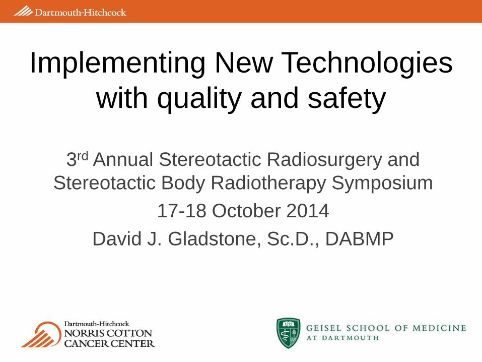
Pre-treatment QA

Isocenter check
0.8 mm

Patient specific localization QA

Confirmation by imaging
Frame based: planar imaging | GTC or Mask: CBCT, 6DOF

GTC pre-treatment checks

Localization QA

Localization QA 2
Need annual QA screen shots and results

Localization QA 3

Isocentricity - Trilogy

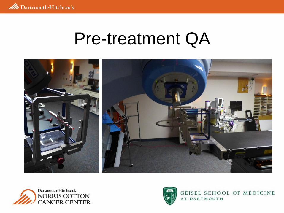
TrueBeam MPC

TrueBeam MPC 2
Trend-lines for all measured parameters
MPC 3
Induced failures

Uncorrelated errors add in quadrature
𝐵𝑅𝑊2 + 𝐶𝑇 𝑣𝑜𝑙𝑢𝑚𝑒2 + 𝐺𝑎𝑛𝑡𝑟𝑦2 + 𝐶𝑜𝑢𝑐ℎ2 + 𝑂𝐵𝐼2
0.192 + 0.31252 + 0.222+.512 +0.52 = 0.8 𝑚𝑚(Trilogy)
0.192 + 0.31252 + 0.312 + 0.22 + 0.32 = 0.6 𝑚𝑚 (TrueBeam)
Image matching uncertainty at treatment…

• Patient comfort
• Ability to plan ahead
• IMRT/VMAT possible
• Multiple lesions – single isocenter
• Image based setup VS mechanical / laser
Frameless motivation

6 DOF for frameless delivery systems
Trilogy with Vision 6DOF TrueBeam with Varian 6DOF
and Vision monitoring

Vision QA

Multiple lesions, single isocenter
with RapidArc

RapidArc DVH

Shielding for fetus

Fetal dose measurements
Without lead With Lead
Whole Brain
3 Gy X 10
6.5 mGy 4.4 mGy
RapidArc
12Gy – 18 Gy
6 mGy 2.2 mGy
• Can we devise a method to directly verify the
correct dose is given to the correct place?
• Radiation is invisible
• Cherenkov emission is VISABLE
Towards WYSIWYG in Rad Onc

The Cherenkov effect – Physical origin
Charged particle at rest Relativistic charged particle

cos𝜃 =𝐴𝐶
𝐴𝐵 =
𝑐
𝑣𝑛=
1
𝛽𝑛
𝑑𝑁
𝑑𝑥= 2𝜋𝛼𝑧2 1 −
1
𝛽2𝑛2
1
𝜆2𝑑𝜆
The ‘Cherenkov’ angle The ‘Frank-Tamm’ formula
The Cherenkov effect – light emission

The Cerenkov effect
Cherenkov radiation and its applications, Jelley
Glaser, et. al., Med. Phys. (2013)
*Strongest in the UV and blue
Dose Production Cerenkov Production
𝑁 =1
𝜌 Φ
𝑑𝑁
𝑑𝑥 𝑑𝐸 𝐷 =
1
𝜌 Φ
−𝑑𝑇
𝑑𝑥 𝑑𝐸

Radiation induced Cherenkov Emission
e-
e-
e-
e-
Photograph of emission ring below water tank
Galvin JCO
2007

Fluorescence randomizes emission direction
Galvin JCO 2007
e-
e-
e-
e-
Galvin JCO 2007
e-
e-
e-
e-
Quinine sulphate
(fluorophore)

Wavelength shifting
Quinine sulphate
(fluorophore)

LINAC Beam Profiling Hardware
ICCD
Water tank
Rotating arm
ICCD
LINAC
Patient
Bed
Water
Tank

Multiple Angle Beam Imaging
Sinogram
Angle
positio
n
0O 90O 180O
Images at different angles
0O 15O 30O 45O
ROTATE
Reconstructed 3D volume with FBP

3D Cherenkography of LINAC Beams
Square beam Complex shaped beam

Medical Linear
Accelerator
Radiation
Beam
Water
Tank
Field of
View
Telecentric
LensCamera
System
yx
zField A
Field B
Primary
Collimator
Multileaf
Collimator
θ
Parallel beam tomography
Field B
Field A
91 projections acquired every 2o
Exposure time: 18 sec.
Total scan time of < 30 min.
Resolution: 1 mm
Reconstructed volume: 10x10x10 cm3

IMRT and VMAT

Predicted versus measured
6MV
Entrance
6MV
Exit
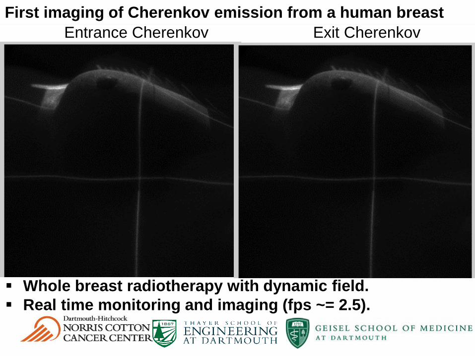
First imaging of Cherenkov emission from a human breast
Whole breast radiotherapy with dynamic field.
Real time monitoring and imaging (fps ~= 2.5).
Entrance Cherenkov Exit Cherenkov

6MV
Entrance
6MV Exit 6MV Entrance
10MV Entrance
6MV Exit
10MV Exit
First imaging of Cherenkov emission from a human breast
Cherenkov emission shows correct beam field shape on body.
Signal from entrance beam shows high superficial dose in axilla, where skin
reactions are common.
Signal from entrance and exit beams show high surface dose in
inframammary fold and near the arm, where skin reactions are also common.

TSE Total Cherenkov mean - bkg

Stereotactic team
Alan
Hartford, MD PhD
Lesley
Jarvis, MD PhDPhil
Schaner, MD PhD
Benjamin
Williams, PhD
Colleen Fox,
PhD

Cherenkography Team
R01CA109558
P30 CA23108
Scott
Davis, PhDAdam
Glaser
Rongxiao
Zhang
Brian Pogue, PhDLesley
Jarvis, MD PhDColleen
Fox, PhD
Audrey Prouty
Development Fund
Chad
Kanick, PhD
Sergei
Vinogradov, PhD
Whitney Hitchcock

“Sometimes you can get shown the light in the strangest of places if you look at it right.”
J. Garcia, R. Hunter
Questions

• Of cancer patients,
• 40 – 85% with spinal mets at autopsy
• 5% with MESCC (>20,000/year in U.S.)1
• 95% extradural (mostly vertebral)
• Survival depends on histology, systemic
disease, functional status
• Pain due to spine metastases is an important
clinical problem
Spine Metastases

• 2/3 patients have pain relief at 3 months
• Common fractionation schemes
• 3Gy X 102Gy X 20 4Gy X 5 8Gy X 1
• No difference in ambulatory rates, but local recurrences
increased in short schedules
• Consider protracted schedules to avoid local recurrences given
the consequences of a failure and difficulty with re-irradiation
• Common techniques
• C spine: opposed laterals
• T spine: PA or AP/PA
• L/S spine: AP/PA
Traditional External Beam RT
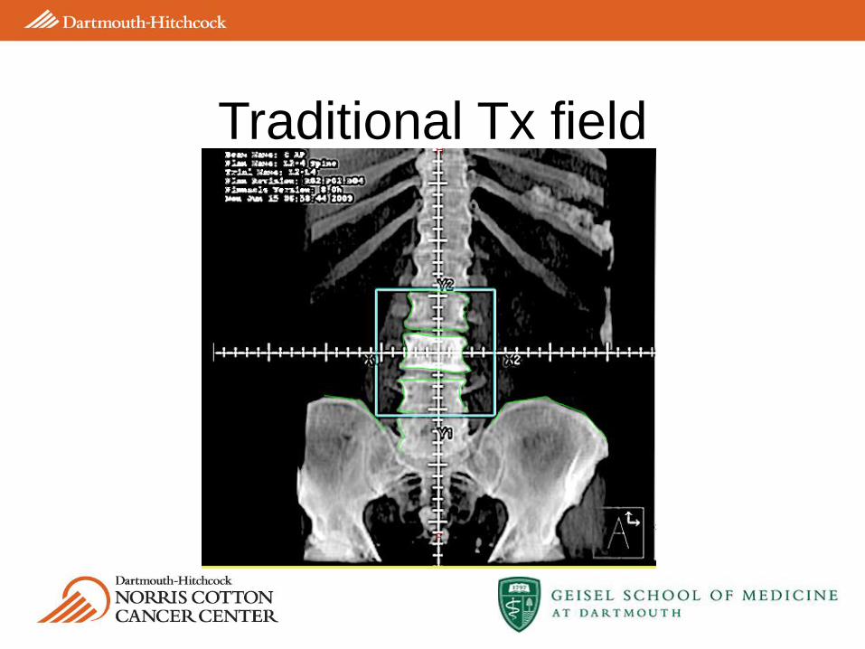
Traditional Tx field

Spine SRS plan

• From experience in brain- 85% local control
• Single day or few days of treatment
• Non-invasive
• Dose escalation while respecting spinal cord tolerance
• Decreased volume of treated bone marrow
• Improved pain control
• Reported results of 80% pain control and 95% LC,
compared to ~60% pain control with fractionated RT
Spine SRS results

• -77 yo man, diagnosed with
prostate cancer in 2003
• -Initially treated with systemic
therapy
• -Disease became androgen
resistant in 2008
• -Received EBRT to prostate and
pelvic LNs in 2008
• -At initial consult: PSA 109, back
pain, bone scan +T10 only, MRI
showed involvement of anterior
and posterior elements, and
involvement of left foramina
Definition of target on CT

RapidArc treatment plan

On board imaging prior to and
during treatment
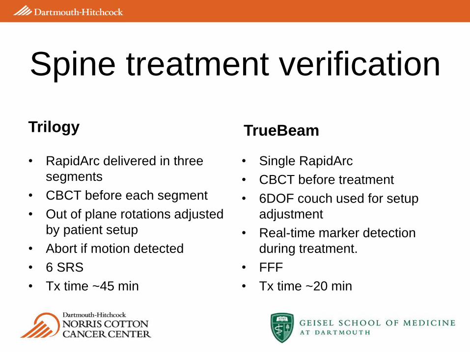
Trilogy
• RapidArc delivered in three
segments
• CBCT before each segment
• Out of plane rotations adjusted
by patient setup
• Abort if motion detected
• 6 SRS
• Tx time ~45 min
TrueBeam
• Single RapidArc
• CBCT before treatment
• 6DOF couch used for setup
adjustment
• Real-time marker detection
during treatment.
• FFF
• Tx time ~20 min
Spine treatment verification

Rotations of cervical vertebrae
C1 C2 C3 C4 C5 C6 C7
-5
0
5
C1 C2 C3 C4 C5 C6 C7
-5
0
5
C1 C2 C3 C4 C5 C6 C7
-5
0
5
C1 C2 C3 C4 C5 C6 C7
-5
0
5
C1 C2 C3 C4 C5 C6 C7
-5
0
5
C1 C2 C3 C4 C5 C6 C7
-5
0
5
C1 C2 C3 C4 C5 C6 C7
-5
0
5
C1 C2 C3 C4 C5 C6 C7
-5
0
5
C1 C2 C3 C4 C5 C6 C7
-5
0
5
C1 C2 C3 C4 C5 C6 C7
-5
0
5
C1 C2 C3 C4 C5 C6 C7
-5
0
5
C1 C2 C3 C4 C5 C6 C7
-5
0
5
C1 C2 C3 C4 C5 C6 C7
-5
0
5
C1 C2 C3 C4 C5 C6 C7
-5
0
5
C1 C2 C3 C4 C5 C6 C7
-5
0
5
% vertebrae
< -3 degrees
% vertebrae
> +3
degrees
% vertebrae
outside ± 3
degrees
Rx rotation 0.6 3.7 4.3
Ry rotation 0 0 0
Rz rotation 1.0 0.4 1.4
-6 -4 -2 0 2 4 60
20
40 Mean = 0.5SD = 1.4
xrot [deg]
Fre
quency
-6 -4 -2 0 2 4 60
20
40 Mean = -0.2SD = 0.8
yrot [deg]
Fre
quency
-6 -4 -2 0 2 4 60
20
40 Mean = -0.2SD = 1.2
zrot [deg]
Fre
quency

• Plan is prepared on
gated scan
• Copied to non-gated
scan to match CBCT
• Dose grid removed
from non-gated scan
to preserve intent
RPM used for lung SBRT

Trilogy
• RPM not integrated
• CBCT – normal mode
• SRS mode (1000) MU/min
TrueBeam
• RPM integrated
• CBCT (extra long)
• Gated fluoro
• Automated marker detection
• FFF (1400 – 2400 MU/min)
Gated treatment details