Implementing JobshopLean in a Castings Repair Facility JobshopLean.pdf · Weld Upgrade Shop....
31
Implementing JobshopLean in a Castings Repair Facility On Site Project Leader: Dan Gallo Industrial Engineering Intern Department of Integrated Systems Engineering The Ohio State University [email protected] Off Site Project Advisor and Faculty Mentor: Dr. Shahrukh Irani Associate Professor Department of Integrated Systems Engineering The Ohio State University [email protected]
Transcript of Implementing JobshopLean in a Castings Repair Facility JobshopLean.pdf · Weld Upgrade Shop....

Implementing JobshopLean in a Castings Repair Facility
On Site Project Leader:Dan GalloIndustrial Engineering InternDepartment of Integrated Systems EngineeringThe Ohio State University [email protected]
Off Site Project Advisor and Faculty Mentor:Dr. Shahrukh IraniAssociate ProfessorDepartment of Integrated Systems EngineeringThe Ohio State [email protected]

2
Summary of Projects
Project 1: Implementation of a pilot manufacturing cell.
Goal : Reduce the number of weld/grind/inspect loops.
Project 2: Implementation of Visual Communication board between weld upgrade and inspection.
Goal: Reduce WIP (work in process) by improving the storage, inventory control and tracking of active orders.
Project 3: Exploit the constraint.
Goal: Increase capacity at the constraint.

3
Project 1: Implementation of a Manufacturing cell
Goal : Reduce number of weld/grind/inspect loops.

4
Sample Routing of Typical Casting
Grinding
Welding
Heat Treat
Inspection
Radiography
Why Create a Manufacturing Cell?

5
Number of Times Casting is Moved= 270
Moves between Weld Upgrade and Inspection = 95
Moves Between Weld, Grind, Inspection = 55
Coun
t
Operation
Count 7 7 7 6 5 5 5 4 3 372 14Percent 25 16 12 8 7 4 3 3
472 2 2 2 2 2 2 1 1 1
345
Cum % 25 41 53 61 67 72 75 77
24
80 82 85 87 88 90 92 93 94 95
19
100
13 8 8
Othe
rQA
CUT
QADOCSB
PWHTLS
ROR
ISTJE
TDY
EW
BFIDIMSKSUB
WEL
DMAGGR
D
80
70
60
50
40
30
20
10
0
Pareto Chart of Operation Performed
Why Create a Manufacturing Cell?Casting Moves and Operational Frequencies for Grind, Weld,
Inspection Loop
Grind, Weld, Magnetic Particle Inspection account for 53% of total operations performed on a casting!
20% of Moves are between Weld, Grind and Inspection
Can We Combine The Grind, Weld & Inspection Operations?
YES!!!!!!
6
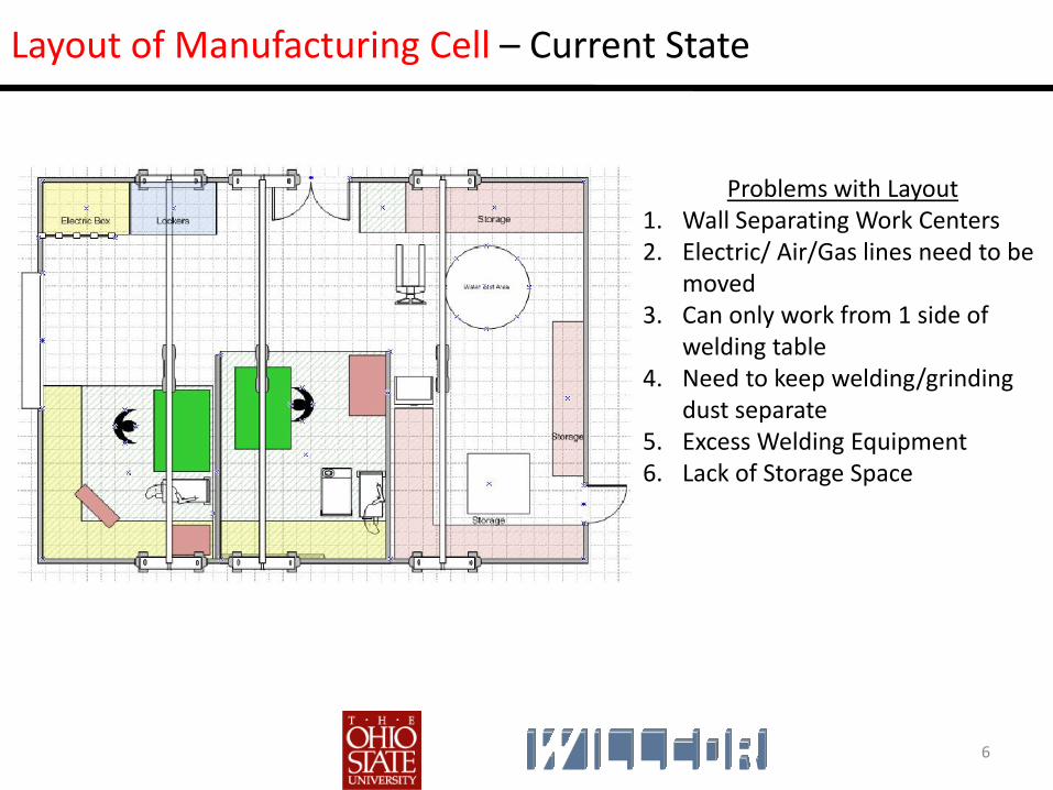
Layout of Manufacturing Cell – Current State
Problems with Layout1. Wall Separating Work Centers2. Electric/ Air/Gas lines need to be
moved3. Can only work from 1 side of
welding table4. Need to keep welding/grinding
dust separate5. Excess Welding Equipment6. Lack of Storage Space

7
Layout of Manufacturing Cell – Current State (Pictures)
Before any changes made.

8
Layout of Manufacturing Cell – Current State (Pictures)

9
Layout of Manufacturing Cell – Phase 1
Changes Made to Layout1. Breakdown Wall and install extra
tall movable welding curtain.2. Move Gas/Air/Electric Lines to
support future layouts.3. Cut welding tables in half place in
center of work area.4. Remove excess welding
equipment.5. Install equipment needed to
perform grinding, welding and magnetic particle inspection operations without moving part.
To Inspection
To W
eld
Upg
rade

10
Layout of Manufacturing Cell – Phase 1 (Pictures)
Before Wall Removed After Wall Removed

11
Layout of Manufacturing Cell – Phase 2, Phase 3, Etc,….
Future Improvements1. Install Roller system to facilitate
worker movement of castings within cell.
2. Establish alternative transportation for parts entering and exiting cell. (Tracks in Floor, motorized pallet jack)
3. Ergonomically friendly work tables. (Able to elevate and rotate)
To Inspection
To W
eld
Upg
rade

12
Layout of Manufacturing Cell – Projected Benefits
Total Part Moves = 270 Total Part Moves = 20026‐ 42% Reduction in Total Part Moves
Weld Upgrade Shop
Inspection Shop
Mag. Test
Weld Grind
Between Shop Moves= 95
Internal Loop= 55
Weld Upgrade Shop
Inspection Shop
Work Cell
In/Out Work Cell= 40
19‐42% Reduction in Rework Loops

13
Layout of Manufacturing Cell – Projected Benefits (Details)
QTY PART # Total Moves Before Cell
Total Moves
After Cell
% Reduction of Total Part
Moves8 A 270 200 26%
8 B 136 101 26%
10 C 218 153 30%
8 D 275 160 42%
Before Cell After Cell
PART # Between Shop Loops
Grind Weld Inspect
Internal Loop
Movement In/Out of
Cell
Re‐Work Loops
ReductionA 95 55 40 42%B 33 25 10 30%C 61 42 12 20%D 77 48 20 26%

14
Project 2: Implementation of Visual Communication board between weld upgrade and inspection.
Goal : Reduce WIP (work in process) by improving the storage, inventory control and tracking of active orders.

15
How the Visual Communication Board Works‐
= 3” x 5” Magnets Move on and off board as castings move from work center to work center
Magnetic Particle Dye Penetrate Dimensional Analysis
Red
Yellow
Green

16
Visual Communication Board In Use‐ Still a Work in Progress….
Drum
Buffer
Rope

17
Goals of Visual Communication Board:
•Facilitate communication between Weld Upgrade and Inspection.
•Gives Foreman the ability to have castings “jump to the front of the line” for expatiated orders.
•Track casting movements in and out of work centers.
•Buffers used as visual queues to establish shop floor space discipline.
•Limit the amount of work entering inspection.
Why Use a Visual Communication Board?

18
Why Use a Visual Communication Board?
Castings Waiting to be released into shop
Foundry Weld Upgrade Inspection
Next Operation…

19
Why Use a Visual Communication Board?
Castings in Weld Upgrade Side of the Facility
Foundry Weld Upgrade Inspection
Next Operation…

20
Why Use a Visual Communication Board?
Castings in Inspection Side of the Facility
Foundry Weld Upgrade Inspection
Next Operation…
WIP!!!

21
Theory of Constraints- Drum- Buffer- Rope
QueueFoundry Weld Upgrade
InspectionNext
Operation…
Drum
Buffer
Rope
Work is Released
Constraint!!!!

22
Visual Communication Boards Locations‐ Again, Drum‐Buffer‐Rope
Drum
Buffer
Rope
Work is Released

23
Project 3: Exploit the constraint!
Goal: Increase capacity at the constraint.

24
Exploit the Constraint‐Work Analysis Study at Constraint
Time Study of Magnetic Particle Inspector
0:00
0:07
0:14
0:21
0:28
0:36
0:43
Remove Old Part from
work station
Grab New part from floor and move into work station
Position New Part and
lower onto work bench
Unstrap Work Piece and move crane
Clamp up work piece
Close Curtin Inspect the Part
Add hoists to part
Paperwork Wait for Crane
Remove part from work station and travel to
spot on floor
Set Up/Travel Time
Inspection Time
Minutes
Total Time Spent at Constraint Work Station= 1 Hour 42 Minutes

25
Exploit the Constraint‐ Separate Job Roles and Do Operations in Parallel
0:00
0:07
0:14
0:21
0:28
0:36
0:43
0 10 20 30 40 50 60
Work to be Done in Parallel
Time Spent by Inspector= 60 Min
Minutes
Minutes
Time Spent by Material Handler= 42 Min
Single Station Wet MT Time Study
Inspector
Material Handler
Total Time Spent at MT work center= 60 Min
Current Weld Upgrade Capabilities1 Wet MT Unit + 1 InspectorTotal Time Spent at MT work center= 102 Min
2 Wet MT Unit + 2 Inspector + 1 Material Handler= Future Weld Upgrade Capabilities
Currently at 100% Capacity
Dual Setup Stations‐‐‐ SHARE THE RESOURCE!!!
Future Capability 100% + 100% + 42% = 242% Capacity

26
Benefits From Three Projects‐Manufacturing Cell
Manufacturing Cell‐
1. 26% ‐ 43% reduction in the total number of part moves throughout the shop
2. 20% ‐ 46% reduction in the number of internal Grind→Weld→Inspectrepair loops

27
Benefits From Three Projects‐ Visual Communication Board
Visual Communication Boards‐
1. Establish drum‐buffer‐rope control between the weld upgrade and inspection.
2. Provides a visual signal to the employees that work can be released into the shop, or parts can be staged as work stations become available.
3. Increase Line Of Sight between work centers by 50%.
4. Ability to track castings progress in real time.
5. Ability to track castings shipped on a weekly basis.
6. Ability to stage work and establish casting precedence as emergent work is revealed.

28
Benefits From Three Projects‐ Exploit Constraint
Exploit Constraint‐
1. Ability to gain 42% capacity at bottle neck by redefining Job Roles to do work in parallel.
2. Possible 142% increase in capacity if additional Inspection equipment is purchased.

29
ProfileA results‐oriented, hands‐on, Industrial Engineer with two years of lean manufacturing and six sigma experience Expertise in low‐volume, high‐mix lean manufacturing and dimensional quality systems.
SkillsSix Sigma‐ Stakeholder Analysis, Project Charter, VOC, VOE, Value Stream Map, SIPOC Map, Pareto Charts, Data Collection Plan, StatisticalSampling, Measurement System Analysis, Histogram, Kaizen, Process Capability, Cp & Cpk ,Cause & Effect Matrix, ANOVA, QueuingTheory, Design of Experiments Full & Fractional Factorial, Quality Function Deployment, FMEA, 5 Why analysis, Regression analysis.
Industrial Engineering‐Work Measurement, Time Studies, Cost‐Benefit Analysis, Process Re‐engineering;Cellular Manufacturing, Line Balancing, Operations Research, Ergonomics, Work force Utilization, Layout Design, Benchmarking, Process Flow Improvement ,Constraint Identification, Replenishment Pull, Mistake‐Proofing, Piloting and Simulation, Visual Process Control, Process Control Plans, Setup Reduction, Drum buffer rope.
Teamwork‐ Demonstrated ability to forge meaningful relationships with various levels of management and shop floor employees.
Presentation Skills‐ Presented executive level presentations, influenced key stakeholders and builder of consensus for sponsorship.
Process Improvement‐ Knowledge of process maturity models and managing resistance to change on both micro and macro level support ability to rapidly asses breakdowns in process and craft solution elements.
Trade Skills‐ Comprehensive in GD&T, Certified FARO Training, and In‐depth knowledge of casting/heat treat process.
Software Skills‐ Excel, Access, Minitab 15, PowerPoint, Microsoft Visual Basic, Arena, PFAST, STORM, Auto‐Cad Inventor, CATIA, Solid Works, AMPL, CPLEX, Dreamweaver, Photoshop, Maple.
Dan [email protected] 513-290-0830

30
Work ExperienceWillcor Consulting, Cornwall Pennsylvania Lean Manufacturing Consultant (2009)Reduced cycle time for large and complex castings in weld upgrade shop supplying parts to US Navy.
•Reduced total part moves by 40% and eliminated 25% of rework loops through implementation of work cell. •Designed and Implemented Drum Rope Buffer queues to control work release into shop and bottle neck. •Lead Kaizen event improving visual communication by 50%. •Assisted with integration of scheduling software to establish job number tracking.
Ashland Incorporated, Dublin, Ohio Lean Six Sigma Green Belt Intern (2008‐ 2009)Team leader for a transactional Lean Sigma green belt project.
•29% reduction in payment discrepancies yielded $100,000+ in hard and soft benefits.•Navigated through DMAIC process tracking process via enterprise tracker. •Provided regular updates with Ohio State Master Black Belt Advisor, Company President and Vice Presidents.
Oshkosh Truck Corporation, Oshkosh, Wisconsin Lean Manufacturing Intern (2008)Quickly learned and applied FARO Technology to improve and control dimensional variation in cab assembly process.
•Designed, tested, and implemented dimensional analysis routines utilizing FARO Arm which yielded a 15% decrease in cycle time at bottleneck on HEMTT Cab Assembly line•Became company subject matter expert in FARO dimensional analysis techniques; trained other personal in use.
Dan [email protected] 513-290-0830
31
EducationB.S. Industrial Systems Engineering, 2009 Ohio State University Columbus, Ohio Overall GPA (4.0 Scale); 3.22; Major GPA: 3.65
Awards and AffiliationsAccenture “Outstanding IE Senior” Award Institute of Industrial EngineersAlpha Pi Mu (Industrial Engineering Honor Society)
Dan [email protected] 513-290-0830