
Implementing Design Principles for Collaborative ERP...
20
Implementing Design Principles for Collaborative ERP Systems ? Wendy Lucas and Tamara Babaian Bentley University, Waltham, MA 02452, USA {wlucas,tbabaian}@bentley.edu Abstract. Enterprise Resource Planning (ERP) Systems are notori- ously difficult for users to operate. We present a framework that consists of a data model and algorithms that serve as a foundation for implement- ing design principles presented in an earlier paper for improving ERP usability. The framework addresses the need for providing user, task and process context of each system-user interaction. It is intended to form an integral part of the system’s data model, which can be queried in real time to produce the information required for a variety of user interface enhancements. We have implemented the framework within an ERP pro- totype and used it in a laboratory emulation of ERP usage. Using the log data from this laboratory emulation, we present examples demonstrat- ing how the framework meets its design goal of providing contextual and historical information. Keywords: Usability, human-computer collaboration, enterprise sys- tems, ERP, human-computer interaction. 1 Introduction and Motivation Enterprise Resource Planning (ERP) systems integrate data and information flow from throughout the organization. Companies rely on them for standardiz- ing their processes around best practices. Rather than the system conforming to the way a particular company does business, the company must conform to the system-prescribed approach in order to reap the maximum benefit. Representing industry-wide rather than company-specific practices places a heavy burden on the user, who must undergo extensive training to learn how to perform particular tasks with the system. Users typically memorize how to do those tasks, as the underlying processes are hidden behind very complex interfaces and little guid- ance or support is provided by the system. The poor usability of ERP systems has been noted in industry reports [16, 22, 15, 17] and our own field studies [26, 10], yet usability problems still abound. Considerable advances in research on ? This material is based in part upon work supported by the National Science Foun- dation under Grant No. 0819333. Any opinions, findings, and conclusions or recom- mendations expressed in this material are those of the authors and do not necessarily reflect the views of the National Science Foundation.
Transcript of Implementing Design Principles for Collaborative ERP...

Implementing Design Principles forCollaborative ERP Systems?
Wendy Lucas and Tamara Babaian
Bentley University, Waltham, MA 02452, USA{wlucas,tbabaian}@bentley.edu
Abstract. Enterprise Resource Planning (ERP) Systems are notori-ously difficult for users to operate. We present a framework that consistsof a data model and algorithms that serve as a foundation for implement-ing design principles presented in an earlier paper for improving ERPusability. The framework addresses the need for providing user, task andprocess context of each system-user interaction. It is intended to forman integral part of the system’s data model, which can be queried in realtime to produce the information required for a variety of user interfaceenhancements. We have implemented the framework within an ERP pro-totype and used it in a laboratory emulation of ERP usage. Using the logdata from this laboratory emulation, we present examples demonstrat-ing how the framework meets its design goal of providing contextual andhistorical information.
Keywords: Usability, human-computer collaboration, enterprise sys-tems, ERP, human-computer interaction.
1 Introduction and Motivation
Enterprise Resource Planning (ERP) systems integrate data and informationflow from throughout the organization. Companies rely on them for standardiz-ing their processes around best practices. Rather than the system conforming tothe way a particular company does business, the company must conform to thesystem-prescribed approach in order to reap the maximum benefit. Representingindustry-wide rather than company-specific practices places a heavy burden onthe user, who must undergo extensive training to learn how to perform particulartasks with the system. Users typically memorize how to do those tasks, as theunderlying processes are hidden behind very complex interfaces and little guid-ance or support is provided by the system. The poor usability of ERP systemshas been noted in industry reports [16, 22, 15, 17] and our own field studies [26,10], yet usability problems still abound. Considerable advances in research on
? This material is based in part upon work supported by the National Science Foun-dation under Grant No. 0819333. Any opinions, findings, and conclusions or recom-mendations expressed in this material are those of the authors and do not necessarilyreflect the views of the National Science Foundation.

2
human-computer interaction [19] have also not resulted in significant improve-ments in ERP system design.
The work presented here is part of a comprehensive research effort aimedat achieving a breakthrough in the usability of enterprise systems by applyingthe human-computer collaboration paradigm [25] to system design and evalu-ation. This paradigm is grounded in theory of collaboration and requires thatthe system act as a partner that supports its users in the increasingly complexenvironments of modern applications [13]. To be a collaborative partner, the sys-tem must do its part by sharing information and adjusting its behaviors basedon its knowledge and awareness of the user, the context of the interaction, andits own functionality. (Note that this is different from Computer-Supported Co-operative Work (CSCW), which is concerned with computing technology thatsupports human collaboration).
In previous work [7], we derived four design principles based on system-usercollaboration for addressing the usability issues identified in our field studies. Inthis paper, we present a representational framework and algorithms that serve asa foundation for implementing these principles. In validating our approach, wefocus here on two of these principles, which are referred to as Design Principle2 (DP2) and Design Principle 4 (DP4). DP2 concerns providing context- anduser-appropriate navigational and progress guidance to the user. DP4 focuseson improving access to data and actions that are most likely to be relevant anduseful. The other two principles, which involve mechanisms for customizationand error handling, are also supported by our framework and are topics of on-going research that is beyond the scope of this paper.
Our framework specifies a model that represents the system’s task structure,interface components, and usage log of all user-system interactions. It has beenspecifically designed to enable the system to make effective use of usage historiesduring system-user interactions. This model, which we refer to as the Task-Interface-Log, or TIL, model, provides the requisite information for supportingthe design principles by explicitly associating low-level user inputs with higher-order processes. Our approach is further distinguished by its use of logged datain support of system-user interactions in real time, as opposed to the off-lineprocessing of logged data for process mining and discovery purposes [2, 23], whichis the more common focus of research involving usage logs in the enterprisesystem domain.
We have implemented the TIL model in SQL and embedded it in an ERPprototype. To evaluate the capabilities of both the TIL model and the algo-rithms for supporting the design principles, we conducted an emulation of theuse of ERP systems in a laboratory setting. The usage data collected from thisemulation was used to validate our approach.
The next section of this paper presents related work. This is followed by de-scriptions of the design principles. We then present our representational frame-work and examples that illustrate the framework’s utility using empirical data.We conclude with a discussion and directions for future work.
3
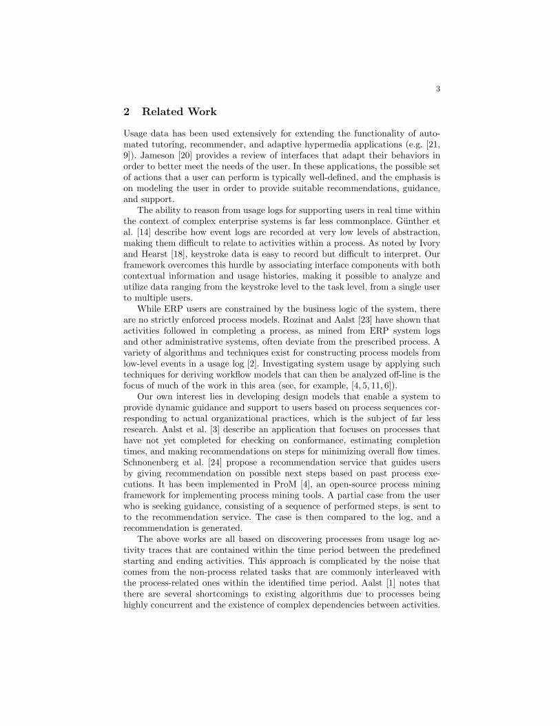
2 Related Work
Usage data has been used extensively for extending the functionality of auto-mated tutoring, recommender, and adaptive hypermedia applications (e.g. [21,9]). Jameson [20] provides a review of interfaces that adapt their behaviors inorder to better meet the needs of the user. In these applications, the possible setof actions that a user can perform is typically well-defined, and the emphasis ison modeling the user in order to provide suitable recommendations, guidance,and support.
The ability to reason from usage logs for supporting users in real time withinthe context of complex enterprise systems is far less commonplace. Gunther etal. [14] describe how event logs are recorded at very low levels of abstraction,making them difficult to relate to activities within a process. As noted by Ivoryand Hearst [18], keystroke data is easy to record but difficult to interpret. Ourframework overcomes this hurdle by associating interface components with bothcontextual information and usage histories, making it possible to analyze andutilize data ranging from the keystroke level to the task level, from a single userto multiple users.
While ERP users are constrained by the business logic of the system, thereare no strictly enforced process models. Rozinat and Aalst [23] have shown thatactivities followed in completing a process, as mined from ERP system logsand other administrative systems, often deviate from the prescribed process. Avariety of algorithms and techniques exist for constructing process models fromlow-level events in a usage log [2]. Investigating system usage by applying suchtechniques for deriving workflow models that can then be analyzed off-line is thefocus of much of the work in this area (see, for example, [4, 5, 11, 6]).
Our own interest lies in developing design models that enable a system toprovide dynamic guidance and support to users based on process sequences cor-responding to actual organizational practices, which is the subject of far lessresearch. Aalst et al. [3] describe an application that focuses on processes thathave not yet completed for checking on conformance, estimating completiontimes, and making recommendations on steps for minimizing overall flow times.Schnonenberg et al. [24] propose a recommendation service that guides usersby giving recommendation on possible next steps based on past process exe-cutions. It has been implemented in ProM [4], an open-source process miningframework for implementing process mining tools. A partial case from the userwho is seeking guidance, consisting of a sequence of performed steps, is sent toto the recommendation service. The case is then compared to the log, and arecommendation is generated.
The above works are all based on discovering processes from usage log ac-tivity traces that are contained within the time period between the predefinedstarting and ending activities. This approach is complicated by the noise thatcomes from the non-process related tasks that are commonly interleaved withthe process-related ones within the identified time period. Aalst [1] notes thatthere are several shortcomings to existing algorithms due to processes beinghighly concurrent and the existence of complex dependencies between activities.
4
In our framework, we avoid many of the challenges inherent in mining-basedapproaches because our model contains the specification of tasks included in theprocess. Our approach is distinguished by the ability to automatically and ac-curately identify process instances based on log records, by virtue of the directrepresentation of tasks, processes and the flow of domain objects in the TILmodel.
3 Design Principles
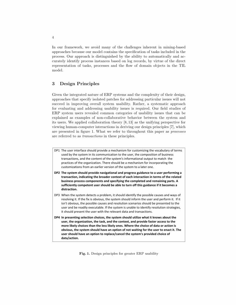
Given the integrated nature of ERP systems and the complexity of their design,approaches that specify isolated patches for addressing particular issues will notsucceed in improving overall system usability. Rather, a systematic approachfor evaluating and addressing usability issues is required. Our field studies ofERP system users revealed common categories of usability issues that can beexplained as examples of non-collaborative behavior between the system andits users. We applied collaboration theory [8, 13] as the unifying perspective forviewing human-computer interactions in deriving our design principles [7], whichare presented in figure 1. What we refer to throughout this paper as processesare referred to as transactions in these principles.
!"# $%&'()&*'+,-&*./0&')%1(23'4*15+3&'/'6&0%/,+)6'.1*'0()-16+7+,8'-%&'510/9(2/*:'1.'-&*6)'()&3'9:'-%&'):)-&6'+,'+-)'0166(,+0/-+1,'-1'-%&'()&*;'-%&'01641)+-+1,'1.'9()+,&))'-*/,)/0-+1,);'/,3'-%&'01,-&,-'1.'-%&'):)-&6<)'+,.1*6/-+1,/2'1(-4(-'-1'6/-0%''-%&'4*/0-+0&)'1.'-%&'1*8/,+7/-+1,='$%&*&')%1(23'9&'/'6&0%/,+)6'.1*'+,01*41*/-+,8'-%&'0()-16+7/-+1,)'.*16'/,'&/*2+&*'5&*)+1,'1.'-%&'):)-&6'-1'/'2/-&*'1,&='
!"# $%&'()(*&+'(%,-./'01,23/&'452365*3,45.'54/'01,61&(('6-3/547&'*,'5'-(&1'0&18,1+346'5'*154(57*3,49'34/375*346'*%&':1,5/&1'7,4*&;*',8'&57%'34*&157*3,4'34'*&1+(',8'*%&'1&.5*&/':-(34&(('01,7&(('7,+0,4&4*('54/'(0&738)346'*%&'7,+0.&*&/'54/'1&+534346'051*(<'='(-88373&4*.)'7,+0&*&4*'-(&1'(%,-./':&'5:.&'*,'*-14',88'*%3('6-3/547&'38'3*':&7,+&('5'/3(*157*3,4<''
!"> ?%&,'-%&'):)-&6'3&-&0-)'/'4*192&6;'+-')%1(23'+3&,-+.:'-%&'41))+92&'0/()&)'/,3'@/:)'1.'*&)125+,8'+-='A.'-%&'.+B'+)'195+1();'-%&'):)-&6')%1(23'+,.1*6'-%&'()&*'/,3'4&*.1*6'+-=''A.'+-'+),<-'195+1();'-%&'41))+92&'0/()&)'/,3'*&)12(-+1,')0&,/*+1)')%1(23'9&'4*&)&,-&3'-1'-%&'()&*'/,3'9&'*&/3+2:'&B&0(-/92&='A.'-%&'):)-&6'+)'(,/92&'-1'+3&,-+.:'*&)12(-+1,')-*/-&8+&);'+-')%1(23'4*&)&,-'-%&'()&*'@+-%'-%&'*&2&5/,-'3/-/'/,3'-*/,)/0-+1,)=''
!"> ?4'01&(&4*346'(&.&7*3,4'7%,37&(9'*%&'()(*&+'(%,-./'-*3.3@&'A%5*'3*'B4,A('5:,-*'*%&'-(&19'*%&',16543@5*3,49'*%&'*5(B9'54/'*%&'7,4*&;*9'54/'01,23/&'85(*&1'577&(('*,'*%&'+,1&'.3B&.)'7%,37&('*%54'*%&'.&(('.3B&.)',4&(<'C%&1&'*%&'7%,37&',8'/5*5',1'57*3,4'3(',:23,-(9'*%&'()(*&+'(%,-./'%52&'54',0*3,4',8'4,*'A53*346'8,1'*%&'-(&1'*,'&457*'3*<'$%&'-(&1'(%,-./'%52&'54',0*3,4'*,'1&0.57&D7547&.'*%&'()(*&+E('01,23/&/'7%,37&',8'/5*5D57*3,4<''
Fig. 1. Design principles for greater ERP usability

5
DP1 grew out of reported instances of users needing to undergo a lengthyprocess, characterized by some as “brutal” and “intimidating,” of learning thelanguage of the system and adapting to its practices. DP2 arose from the diffi-culties users face in understanding the process flow and navigating the system,with little support on how to proceed or what progress has been made. DP1 andDP2 are meant to address the failure of the system to be a good collaborativepartner by communicating its knowledge concerning the steps that need to betaken, the means for performing them, and the progress made toward achievingthe goal.
Numerous reports by users of their inability to determine the cause of anerror, decipher error messages, or figure out how to address the problem ledto the statement of DP3. In such cases, the system is failing to help a partnerin need. Lastly, DP4 grew out of observed and reported cases of the systempresenting all possible choices, even those that will not work in the currentsituation, in search interfaces, lists, etc., and failing to take the user’s previousentries and actions into account. In these cases, the system has not providedappropriate support to assist the user in daily operations.
The framework presented in this paper provides the information needed forsupporting all four principles. We have limited our validating examples in thenext section to two of these, DP2 and DP4, due to space limitations. Examplesrelated to DP1 and DP3 will be presented in future work.
4 Representational Framework
In this section, we present the representational framework that we developedto support implementation of the design principles. The design goals behindthis framework originated from the requirements on the system’s awareness ofhistorical and contextual data, as necessitated by the design principles:
1. to represent the system’s task and interface structure in a way that enablesreasoning about their relationship to each other and to the ERP domaindata in the context of a business process,
2. to capture and store the history of each system-user interaction in a waythat enables a quick identification of the task and user context of all pastand on-going interactions, as well as recording the lower-level keyboard andmouse input details, and
3. to make the knowledge included in the first two items accessible to thesystem at run-time for supporting a variety of implementations of the designprinciples.
The framework includes the Task-Interface-Log (TIL) data model, algorithmsfor deriving process-related data, and input-aware components. The followingsections describe the model and algorithms. While the components have alsobeen implemented, they are not reviewed here.

6
4.1 Overview of the TIL modules: Task, Interface, Logging
At the core of our representational framework is the TIL data model for repre-senting Tasks and their inclusion in business processes, the Interface componentsthat implement them, and usage Logs that store the details of system-user in-teractions.
The Task module of the TIL model captures the description of tasks that thesystem implements and their inclusion in business processes. The set of interfacepages associated with each task is described in the Interface module. This modulealso describes the composition of each interface page from user input controls,such as input fields, buttons, and menus. The descriptions within the Task andInterface modules are static, in that they do not change with use of the system,with one exception that allows the system to be configured with business processspecifications as desired collections of tasks. The data within these two modulesis used to render interface pages, when the user invokes a task interface, and fortracking the task and process context of each interaction.
The Logging module records user interactions with the system on two inter-connected levels: the task level and the interface level. Logging on the task levelinvolves keeping track of task instances, i.e., the user’s engagement with the sys-tem on a particular task. A task instance can extend over multiple user-sessions,and the Logging module chronicles the execution of a task instance from thebeginning to the end.
The interface layer log stores the detailed key-press level information regard-ing the user’s interactions with input controls within the task. To support usagedata capture, we have implemented and used a library of user input compo-nents that record the interaction data. Taken together, the information containedwithin these two layers of the Logging module enables a quick and complete re-construction of a sequence of events as they occurred over time.
The records of organizational data, such as customers, vendors, and invoices,are stored in the ERP system database, which we refer to as the Domain module.We call Domain module entities domain objects and their corresponding tablesobject types.
Definition 1. A domain object is a record from a table in the Domain module.The domain object type, or simply object type, is the name of the table in theDomain module storing the domain object.
All three modules of the TIL model are also related to the Domain module- these relationships specify the flow of organizational data through the tasks.In particular, each task description (Task module) includes a specification ofthe type of organizational data object that the task produces, called the task’soutput object type. For example, the Add Material task produces a record in theMaterial table; thus, it’s output type is Material. The references to the actualobjects (e.g. a concrete Material record) produced as a result of a specific taskinstance are contained within the Logging module’s record of task instances.
Along with the output object type for a task, the TIL model also includesinformation on each task’s input object types. Each user input component de-

7
scription in the Interface module specifies the type of object that should beentered in the field. Since each input component is associated with a task, theTIL model enables the derivation of the set of input objects used in a task.
4.2 TIL relations
This section introduces the details of the TIL model that are essential to thealgorithms and derivations that follow. Boldface is used to denote the names ofthe relations, and italics is used for the attributes. The relations are defined overstandard SQL types, such as varchar, int and datetime. Please refer to figure 2for descriptions of the attributes of each relation that we review below.
The Domain module represents the ERP organizational data and is not partof TIL, but TIL model relations reference the Domain module tables that storea variety of domain objects. The User relation of the Domain module has aspecial significance, because it is linked to all usage log related records. Forthe sake of simplicity, we model the User relation as consisting of the singleidentifier attribute UID. Other attributes describing the user’s relationship witha particular organizational unit, role, or set of permissions within the systemcould be added for greater richness of informational queries from the log data,but such treatment of User is not included in this paper.
The Task module consists of three relations: Task,Process and ProcessTasks.The DTableOut attribute of the Task table refers to the task’s output typewhich, as we defined in section 4.1, is the name of a table from the Domainmodule that stores the output objects associated with that task. The Processand ProcessTasks tables list the business processes and specify which tasks areincluded in each process, respectively.
The Interface module represents user interface components and their orga-nization and relationship with the Task and Domain modules. Each Task isassociated with a set of distinct TaskPages which, in turn, consist of Groupsof InputControls.
The InputControl table describes interactive GUI elements such as buttons,text fields, lists, and menu items. Input control records for text fields specify inthe DTable column the type of object that must be entered into the text field. Forexample, a field designated for a customer number will have the DTable attributevalue equal to Customer, which is the table storing customer information inthe Domain module. The DTable column of input controls used for enteringnon-domain object data, such as an order quantity or a delivery date, has novalue.
The Logging module records the usage history and describes the relationshipsbetween click-level and keyboard-level data, users, and tasks.

8
Module Description
Domain User U User description UID User Identifier (PK)others omitted
Task Task T Task description TID Task Identifier (PK)Tname Task nameDTableOut Task output type(Domain table name)
Process PR Process Description PRID Process Identifier (PK)PRName Process name
ProcessTasks PRT Tasks included in process PRID Process identifierTID Task identifierOpt Task optional or required status
Interface Task Page TP PID identifierTID Task identifier
Group G GID Group IdentifierPID Task Page Identifier
Input Control IC User input component ICID Input Control Identifier (PK)GID Group IdentifierDTable Input Object Type (Domain table name)
!"##$%# User Session !" SID Session Identifier (PK)UID User Identifierts Time session startedte Time session ended
Task Instance #$ TIID Task Instance Identifier (PK)TID Task Identifier ts Start time of task instance te End (completion) timeOutPKVal Output object produced by the task instance
"#$ STIID Session Task Inst. Identifier (PK)TIID Task Instance IdentifierSID Session Identifier ts Start time of session task instancete End time of session task instance
Entry Field EF Input control instantiations EFID Entry Field Idenetifier (PK)&'&( Input Control Identifier SID Session Identifier TIID Task Instance Identifier
User Entry UE UEID User entry record (PK)EFID Entry Field Idenetifier ts Start time of user input (focus-in)te End time of user input (focus-out)Vs Value in field at the start timeVe Value in field at the end timeE user input
Timed user input per entry field
Task instance breakdown by user session
User session - continuous period between the time user logs in and out of the system.
Task instance - an instantiation of a task, possibly spanning multiple user sessions between start and completion.
Session Task Instance
Relation and Abbreviation Atributes and their descriptions
Interface pages associated with each task
Group of input controls on a page
Fig. 2. A summary of the essential components of the TIL model and the Domainmodule.
The UserSession relation represents periods of time during which the useris continuously logged in to the system. It is used to relate each interaction to aparticular user.
The TaskInstance relation records instantiations of tasks. A new task in-stance record is created each time the user opens a new task. The task instanceend time corresponds to the moment when the user either cancels the task in-stance or completes it, in which case the output is saved in the Domain database.

9
The identifier of the output object is stored in the outPKVal column of the TaskInstance record.
As the task instances can span multiple user sessions, the SessionTaskInstancerelation is used to record the task instance execution times within different ses-sions.
Taken together, the UserSession, TaskInstance and SessionTaskInstancerelations specify the user and task context of system-user interactions. The de-tailed log of system-user interactions within the task instances is stored withinthe EntryField and UserEntry relations, described next.
The EntryField table represents the instantiations of input controls corre-sponding to a specific task instance and user session. The ICID attribute refersto the instantiated input control. SID and TIID are references to the sessionand task instances, respectively, in which the entry field was created.
The UserEntry relation records the user input directed to the specifiedentry field. The start and end times of the period when the entry field is incontinuous focus are defined by ts and te . Attributes Vs and Ve record the valuein the text field at the start and the end of that time period, while E denotes astring recording the user’s input as a sequence of keystrokes or mouse events.
4.3 Task and process graphs and algorithms
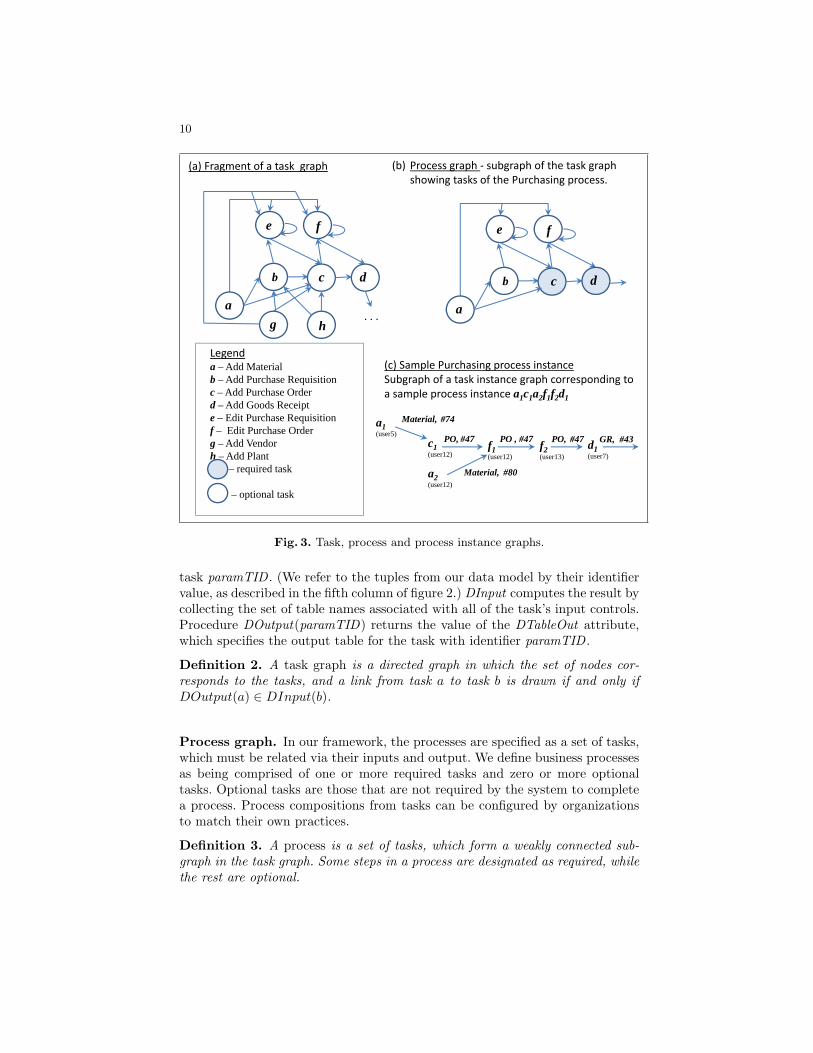
To provide context-aware guidance and navigational support for design principleDP2 requires that the system be aware of the relationships between the tasksand the input-output flow of objects between them. The TIL model specifiesthe input and output types of tasks in a process and, during runtime, recordsthe actual domain objects that are instantiated. This information enables theautomatic determination of the relationships between task and task instances ina chain comprising a business process. Figure 3 illustrates the types of task andprocess-related information that we focus on in this section.
Task graph. Figure 3(a) presents a fragment of a system task graph that can becomposed from descriptions contained within the Task and Interface modules.The nodes correspond to tasks, and an arrow from one node to another designatesthat the output of the source task may be used as an input to the target task.For example, arrows from task a, Add Material, lead to tasks b, c, e, and f . Thisis because these four tasks have Material as part of their input, which can beestablished by querying the TIL model records on the input fields for these tasks.
The task graph is composed from the TIL model data using proceduresDInput and DOutput , which stand for Domain Input and Domain Output andare depicted in figure 4. We use relational algebra operations [12] of naturaljoin (∗), projection (π), selection (σ) and renaming (ρ). We use the abbreviatednames of the TIL relations, as presented in the third column of figure 2. Up-percase letters used here and throughout the paper denote relations, while thenames of scalar values and individual tuples begin with a lowercase letter.
Procedure DInput(paramTID) returns a set of domain input types of taskparamTID , i.e. the types of domain objects that can be entered as an input to
10
b
e f
c
ag h
d
. . .
b
e f
c
a
Legenda – Add Materialb – Add Purchase Requisitionc – Add Purchase Orderd – Add Goods Receipte – Edit Purchase Requisitionf – Edit Purchase Orderg – Add Vendorh – Add Plant
– required task
– optional task
(a) Fragment of a task graph (b) Process graph ‐ subgraph of the task graph showing tasks of the Purchasing process.
(c) Sample Purchasing process instanceSubgraph of a task instance graph corresponding to a sample process instance a1c1a2f1f2d1
c1(user12)
Material, #74
f1(user12)
PO, #47
a2(user12)
Material, #80
a1(user5)
f2(user13)
PO , #47 PO, #47
d
d1 (user7)
GR, #43
Fig. 3. Task, process and process instance graphs.
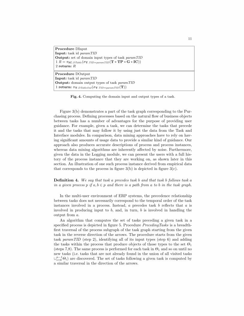
task paramTID . (We refer to the tuples from our data model by their identifiervalue, as described in the fifth column of figure 2.) DInput computes the result bycollecting the set of table names associated with all of the task’s input controls.Procedure DOutput(paramTID) returns the value of the DTableOut attribute,which specifies the output table for the task with identifier paramTID .
Definition 2. A task graph is a directed graph in which the set of nodes cor-responds to the tasks, and a link from task a to task b is drawn if and only ifDOutput(a) ∈ DInput(b).
Process graph. In our framework, the processes are specified as a set of tasks,which must be related via their inputs and output. We define business processesas being comprised of one or more required tasks and zero or more optionaltasks. Optional tasks are those that are not required by the system to completea process. Process compositions from tasks can be configured by organizationsto match their own practices.
Definition 3. A process is a set of tasks, which form a weakly connected sub-graph in the task graph. Some steps in a process are designated as required, whilethe rest are optional.
11
Procedure DInputInput: task id paramTIDOutput: set of domain input types of task paramTID1 R = πIC.DTable(σT.TID=paramTID(T ∗TP ∗G ∗ IC))2 return: R
Procedure DOutputInput: task id paramTIDOutput: domain output types of task paramTID1 return: πT.DTableOut(σT.TID=paramTID(T))
Fig. 4. Computing the domain input and output types of a task.
Figure 3(b) demonstrates a part of the task graph corresponding to the Pur-chasing process. Defining processes based on the natural flow of business objectsbetween tasks has a number of advantages for the purpose of providing userguidance. For example, given a task, we can determine the tasks that precedeit and the tasks that may follow it by using just the data from the Task andInterface modules. In comparison, data mining approaches have to rely on hav-ing significant amounts of usage data to provide a similar kind of guidance. Ourapproach also produces accurate descriptions of process and process instances,whereas data mining algorithms are inherently affected by noise. Furthermore,given the data in the Logging module, we can present the users with a full his-tory of the process instance that they are working on, as shown later in thissection. An illustration of one such process instance derived from empirical datathat corresponds to the process in figure 3(b) is depicted in figure 3(c).
Definition 4. We say that task a precedes task b and that task b follows task ain a given process p if a, b ∈ p and there is a path from a to b in the task graph.
In the multi-user environment of ERP systems, the precedence relationshipbetween tasks does not necessarily correspond to the temporal order of the taskinstances involved in a process. Instead, a precedes task b reflects that a isinvolved in producing input to b, and, in turn, b is involved in handling theoutput from a.
An algorithm that computes the set of tasks preceding a given task in aspecified process is depicted in figure 5. Procedure PrecedingTasks is a breadth-first traversal of the process subgraph of the task graph starting from the giventask in the reverse direction of the arrows. The procedure starts from the giventask paramTID (step 2), identifying all of its input types (step 6) and addingthe tasks within the process that produce objects of those types to the set Θ1
(steps 7,8). The same process is performed for each task in Θ1 and so on until nonew tasks (i.e. tasks that are not already found in the union of all visited tasks∪n−1
i=0 Θi) are discovered. The set of tasks following a given task is computed bya similar traversal in the direction of the arrows.

12
Procedure PrecedingTasksInput: task id paramTID , process id paramPRIDOutput: set of tasks preceding task paramTID in process paramPRID1 n = 02 Θ0 = {paramTID}3 do4 n = n + 15 for each taskTID ∈ Θn−1
6 InputTypeSet = DInput(taskTID)7 for each objType ∈ InputTypeSet8 Θn = Θn ∪ ProducerTasks(objType, paramPRID)− ∪n−1
i=0 Θi
9 while (Θn 6= ∅)10 return: ∪n
i=1Θi
Procedure ProducerTasksInput: domain object type paramObjType, process id paramPRIDOutput: task ids for task from process paramPRID outputting objects of typeparamObjType1 return: πT.TID(σT.DOutputType=paramObjType∧PRT.PRID=paramPRID(T ∗PRT))
Fig. 5. Computing the set of tasks preceding a given task in a specified process.
Task instance graph and process instance identification. The TIL modelalso provides for an easy and noiseless reconstruction of process instances, i.e.sets of task instances corresponding to a specified process, regardless of the orderin which they have been executed and the number of users involved.
We introduce below two auxiliary procedures, TIIn and TIOut, which standfor Task Instance Input and Output, respectively. Shown in figure 6, these proce-dures return the actual inputs and output objects of a given task instance. Bothare used in a process instance identification procedure, whose definition followsin figure 7. The identification procedure is based on a domain object producedas an output and can be best understood as a breadth first traversal of the taskinstance graph.
Procedure TIIn(paramTIID) returns a list of (objectType, objectID) pairsfor those objects entered into the entry fields associated with paramTIID . Todetermine which object id was entered, a query selects the chronologically lastvalue of an entry field recorded in the UserEntry relation. To perform thisselection, steps 1-2 of the procedure compute the complete set of user entriesinto the entry fields associated with task instance paramTIID . Based on thetiming of the user entries, steps 3-4 produce the set of final values for each entryfield, i.e. the values that were actually submitted. From those final values andthe description of their domain type stored in the InputControl relation, step5 composes a set of (objectType, objectID) pairs, where objectID is the valueentered in the field, and objectType specifies its domain type.
TIOut(paramTIID) returns the output object type and id of the task instanceparamTIID from the Task and TaskInstance relations.

13
Procedure TIInInput: task instance id paramTIIDOutput: set of pairs (objectType, objectID) used as input to paramTIID1 J = σTI.TIID=paramTIID(TI) ∗EF ∗ IC ∗UE2 K = σIC.DTable!=null∧UE.Ve!=null(J)3 L = ρLast(EFID,te)(EFIDFMAXte
(UE))4 M = σUE.te=Last.te(K ∗ L)5 R = ρTIIn(objectType,objectID)(πIC.DTable,UE.Ve(M))6 return: R
Procedure TIOutInput: task instance id paramTIIDOutput: pair (objectType, objectID) describing the type and value of domain outputof paramTIID1 return: πT.DTable,TI.OutPKV al(σTI.TIID=paramTIID(TI ∗T))
Fig. 6. Procedures computing the input and output of a specified task instance.
Definition 5. A task instance graph is a labeled directed graph in which the setof nodes corresponds to the task instances, and a link from task instance a totask instance b with label o = TIOut(a) is drawn whenever TIOut(a) ∈ TIIn(b)and a.te < b.ts, where ts and te refer to the task instance start and end time.
The process instance information can be explored in a number of useful ways,including:
1. identifying all complete or incomplete instances of a given process, or for agiven user,
2. given an object, such as a goods receipt, identifying all the task instanceswithin the process involved in creating that object, and
3. identifying all instances of a process that use a given object, such as a pur-chase requisition, as their input.
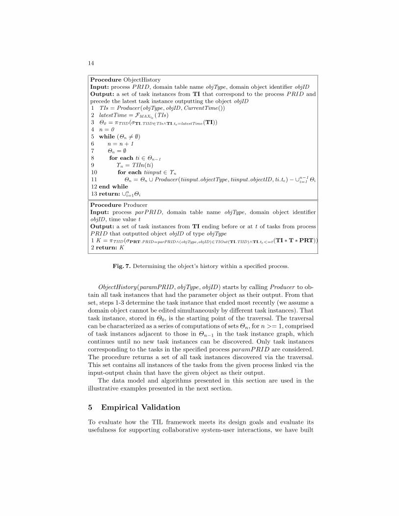
As an illustration, figure 7 presents a procedure called ObjectHistory thatdetermines, for a given process and a given domain object, the part of thatprocess that led to the current state of that object. The algorithm is a breadth-first traversal of the task instance graph induced by the Logging module. Thetraversal is performed in the reverse direction of the arrows, starting from thechronologically latest task instance that has the given domain object as its out-put. The traversal is complete when all task instances that are a part of thegiven process are identified. The output of the procedure is a set of task in-stances that correspond to the steps of the input process up to the point of thelatest modification of the input object.
Procedure Producer , shown in figure 7, is called by ObjectHistory and returnsthe task instances corresponding to a given process paramPRID that have aspecified object as their output. Only task instances that ended before a specifiedtime are returned.
14
Procedure ObjectHistoryInput: process PRID, domain table name objType, domain object identifier objIDOutput: a set of task instances from TI that correspond to the process PRID andprecede the latest task instance outputting the object objID1 TIs = Producer(objType, objID ,CurrentTime())2 latestTime = FMAXte
(TIs)3 Θ0 = πTIID(σTI.TIID∈TIs∧TI.te=latestTime(TI))4 n = 05 while (Θn 6= ∅)6 n = n + 17 Θn = ∅8 for each ti ∈ Θn−1
9 Υn = TIIn(ti)10 for each tiinput ∈ Υn
11 Θn = Θn ∪ Producer(tiinput .objectType, tiinput .objectID , ti .te)− ∪n−1i=1 Θi
12 end while13 return: ∪n
i=1Θi
Procedure ProducerInput: process parPRID, domain table name objType, domain object identifierobjID , time value tOutput: a set of task instances from TI ending before or at t of tasks from processPRID that outputted object objID of type objType1 K = πTIID(σPRT.PRID=parPRID∧(objType,objID)∈TIOut(TI.TIID)∧TI.te<=t(TI ∗T ∗PRT))2 return: K
Fig. 7. Determining the object’s history within a specified process.
ObjectHistory(paramPRID , objType, objID) starts by calling Producer to ob-tain all task instances that had the parameter object as their output. From thatset, steps 1-3 determine the task instance that ended most recently (we assume adomain object cannot be edited simultaneously by different task instances). Thattask instance, stored in Θ0, is the starting point of the traversal. The traversalcan be characterized as a series of computations of setsΘn, for n >= 1, comprisedof task instances adjacent to those in Θn−1 in the task instance graph, whichcontinues until no new task instances can be discovered. Only task instancescorresponding to the tasks in the specified process paramPRID are considered.The procedure returns a set of all task instances discovered via the traversal.This set contains all instances of the tasks from the given process linked via theinput-output chain that have the given object as their output.
The data model and algorithms presented in this section are used in theillustrative examples presented in the next section.
5 Empirical Validation
To evaluate how the TIL framework meets its design goals and evaluate itsusefulness for supporting collaborative system-user interactions, we have built

15
a prototype ERP system that utilizes the TIL model. We have conducted anemulation of ERP usage in an organization using our prototype in a laboratorysetting. The emulation involved 15 users performing typical ERP tasks over aperiod of 27 days, with overall logged usage time of a little under 12.5 hours.There were 39 user sessions that resulted in 6,691 separate user entries. Theusers accessed a total of 15 different task pages, which created approximately450 different task instances.
We have tested all algorithms presented in the previous section on the usagedata collected during the emulation. Here, we present examples that demonstratethe usefulness of our framework for supporting design principles DP2 and DP4using the emulation data.
5.1 Example 1: implementing Design Principle 2
Design principle 2 mandates that the user performing a business process beassisted by having the system display navigational guidance through completedand remaining tasks. This guidance should take into account the task and processcontext. It is easy to see that the TIL representation and algorithms presented inthe previous section directly support derivations of context and process guidanceinformation.
Figure 8 shows a design of an interactive display visualizing the tasks thatprecede and follow the user’s current task. This display was constructed from theemulation data using the data and algorithms presented in the previous section.It includes the Purchasing process task information and references to the taskinstances related to the Add Purchase Order task instance.
Add Material
Add Purchase RequisitionEdit Purchase Requisition
Material #74 Nov 11, 17:11 Material #80 Dec 2, 10:57
‐‐‐‐‐‐‐‐‐
‐‐‐‐‐‐‐‐‐
Edit Purchase OrderAdd Goods Receipt
Current task: Add Purchase Order PO #47 Dec 2, 10:59
Precede
Follow
PURCHASING process tasks Current process instance:task instance outcome , date
Fig. 8. An interactive display showing a Precede/Follow list, providing quick access torelated tasks, objects and task chronology.
The left side of the display in figure 8 specifies the tasks, separated intothose that can precede the current task and those that can follow it. As definedin section 4.3, preceding tasks are those that are involved in producing the input
16
to the current task and are obtained by executing the PrecedingTasks procedure(fig. 5), which derives the information from the Task and Interface modules ofTIL. The Precede/Follow list highlights in boldface the tasks that are requiredfor the process. It also serves as a useful reminder of the tasks related by theinput-output flow and as a navigation tool: given that each task is associatedwith its interface page specification, a task name can also link to the appropriatetask page.
The number of instantiations of each preceding task and the timing of each isincluded in the instance-specific information on the right side of the interactivedisplay. The figure shows that the currently active task instance of Add PurchaseOrder was preceded by two Add Material instances. The other two precedingtasks are optional, and are not present in this process instance. This data isproduced using the algorithm presented in figure 7, which returns a list of taskinstances within the process that are involved in producing the object createdby the current task. The data includes the objects created by each precedingtask instance and the date that the task instance was completed. Clicking onthe object description (e.g. Material #74) will display the object. The user canalso sort the list of preceding instances by the completion date to see the actualchronology of the process instance.
5.2 Example 2: Implementing Design Principle 4
A core proposition of DP4 is that the system should make use of what it knowsabout the user, the organization, the tasks, and the context to provide fasteraccess to more likely choices. Software systems often do make use of prior userinteractions for assisting with data entry. For example, in filling out a form onthe Web, the browser will typically display one or more values that the user hadpreviously entered to a field. With the knowledge represented by the TIL model,the system can provide access to values previously entered by the current user aswell as by other users performing a particular task. The latter can be especiallyhelpful to users with limited usage histories of their own. The granularity ofusage data in our model also makes it possible to determine the users experienceat a detailed level, so that appropriate assistance can be offered not only tousers who are novices with the system overall, but also to those with limitedexperience in a particular task or even with a particular component within atask.
To demonstrate the type of information available to the system for use intailoring the support it offers on a task-by-task basis, table 1 contains data fromour laboratory study showing the users who submitted the Purchase Requisition(PR) Enter Header and Defaults page during a two-day period, the number oftimes they submitted, and the date of their most recent submission.
For those users with recent and frequent experience in submitting purchaserequisitions, default values based on prior entries are likely to be the most use-ful. For someone with little or no experience, however, knowledge of the valuesentered by other users performing the same task can be very helpful. Valuespreviously entered to a field can be sorted by frequency of entry, the most recent

17
!"#$%&' ($#)*#+,-./%01+#%&2#3"%4%56"2%/#,#+2%
7*831""16+*"#$9: ; ;<4=>?%9@A9B*"#$C ; ;<4=>?%9;A9D*"#$E ; ;@4=>?%9<ABB*"#$F @ ;@4=>?%9<A;F*"#$D ; ;@4=>?%9:AB:
Table 1. Count of submissions and time stamp of most recent submission of PR Headerand Defaults page during a two-day period
date of entry, or any other useful property. Table 2(a) shows the values enteredby all users into the Plant field in the PR header and defaults page during a two-week time period. The most frequently entered value during that time periodwas 15, which was also the value entered most recently. This type of informationcan be used in guiding a user with limited experience in filling out any formwithin the system.
(a)
!"#$% &'%($%)*+,-./01%*%)/02)/'+0
3"/%
45 6 7832904:;6:44 7 78329046;6:4< 7 783290=;7647 7 7:8>?!046;454: 7 7832904<;5@46 4 78329047;:5A 4 7832904<;:5 (b)
!"#$%&'("%)(*&+!',
!'&-./0 1.%.&23#0455066&'($"%6
7 8*."% 9"% :;< 10*9=0)3&1.%0 142> :?@ A%().B0&C(5.D(" 9"% EEF G0"H() 9"% :F
:?7 4HH&8*."% /0"$9%0/ ?:?< >H9%&8*."% /0"$9%0/ ?;?7 4HH&G0"H() /0"$9%0/ ?;?< >H9%&G0"H() /0"$9%0/ ?
Table 2. (a) User-entered values during two-week period into Plant field in PR Headerand Defaults page; (b) Access counts for all input controls in the PR Header andDefaults page
DP4 also specifies that, if a choice of data or action is obvious, the systemshould have the option of enacting it, with the user able to replace or cancel thataction. If a user almost always enters the same plant value in filling out a PR,for example, then it would make sense for the system to enter that value for theuser. Similarly, if the user typically enters multiple PRs, as evidenced from thelog, then the system should let the user cycle through the PR process multipletimes, while also providing easy access to other frequently performed tasks.
The data captured to the usage log also provides insights into the practicesof the organization that can be used for assisting the user. As an example,consider the fields that the organization requires users to fill in versus those
18
required by the ERP system. While the latter may (or may not) be markedas required in the system, there is typically no discernible way for users to seewhat fields must be entered in order to adhere to organizational practices; thisis because customization is costly and difficult to maintain when systems areupgraded. The system, however, does have knowledge of which fields are mostoften completed, or left blank; which options are most typically selected, orignored, etc. Highlighting fields that are typically filled in can help improve theusers’ efficiency in filling out forms, particular those with which they have lessexperience.
As an example, table 2(b) shows the number of times each of the inputcontrols in the PR header and defaults page were accessed. While storage locationis not a required field, it was the most frequently accessed field. Table 2(b)also shows that none of the menu items were accessed from this page, as therewere other ways of navigating that were chosen instead. Because ERP systemsare designed to meet the needs of a vast array of users in varying industries,there will typically be fields or options on every page that are not needed byparticular groups of users. The system can be designed to not include thosecomponents when rendering the interface. In particular, the removal of fields thatare never filled in because they are not relevant to a particular organization’spractices can lessen interface complexity and improve user efficiency. For othercomponents, such as the menu items in Table 2(b) and other navigational aids,it could be that the user is just not aware of them but they could actually bebeneficial (as evidenced by another group of users making frequent use of them,for example). The system could be designed to direct the user’s attention tohitherto unexplored options based on its knowledge of overall system usage.
6 Conclusions and Future Work
We have presented a framework, consisting of the TIL data model and algo-rithms, that was designed as a foundation for implementing design principlesfor achieving greater ERP system usability. The framework was implementedwithin an ERP prototype and tested using data obtained in a laboratory emu-lation of ERP usage in an organization. The evaluation confirmed that the TILmodel meets its design goals of supporting context-aware system interactions byenabling real-time querying of contextual and historical information in supportof the design principles from section 3.
The task and process specifications contained within the TIL model structurealone (without the usage log data) make it possible to identify all of the tasksthat lead to the creation of a specific type of object and all of the subsequenttasks in which that output can be used. The TIL model can also be exploited forproviding support to users by informing them, for example, of the flow of outputsthrough the system leading to the task currently being worked on. Analysis ofthe usage data within the TIL model provides the larger picture of the manypossible ways that users can complete processes with the system, which can be
19
applied to navigational support, guiding the user in input choices and actions,and providing access to data and actions that are most likely to be useful.
A limitation of the presented framework is that tasks are described as havingonly one output: while many ERP tasks can be characterized in this way, thereare some tasks that produce more than one object type. The model and algo-rithms can be extended to handle multiple output objects in a straightforwardway.
Compared to the related work in workflow mining, which addresses some ofthe same aspects of system behavior, our approach is both model- and log-data-driven rather than being based solely on usage log data. This results in severaladvantages, including accurate and complete process instance identification re-gardless of the number of process instances in the log, and the ability to provideuser guidance that is based on the model of tasks, processes and object flow.
In this paper, we provided examples illustrating the utility of the frameworkfor implementing two of the four principles, DP2 and DP4. The framework alsoprovides a foundation for several aspects of the other two principles. Indeed, thedeclarative description of tasks and related user interface components enablesthe easy customization of the system’s vocabulary. The process descriptions inthe TIL model provide a mechanism for process customization, as required byDP1. DP3 involves reasoning about errors, which is not addressed by the modelpresented here, but the TIL model already contains components that are a nec-essary part of error-related support of the user. In the future, we will extendthe framework to fully support all four design principles. We will also developproof-of-concept implementations of the kinds of interface features described insection 5 and evaluate them in user studies.
References
1. van der Aalst, W.M.P.: Process discovery: Capturing the invisible. IEEE Comp.Int. Mag. 5(1), 28–41 (2010)
2. van der Aalst, W.M.P.: Process Mining: Discovery, Conformance and Enhancementof Business Processes. Springer Publishing Company, Incorporated, 1st edn. (2011)
3. van der Aalst, W.M.P., Pesic, M., Song, M.: Beyond process mining: From the pastto present and future. In: CAiSE. pp. 38–52 (2010)
4. van der Aalst, W.M.P., Reijers, H.A., Weijters, A.J.M.M., van Dongen, B.F.,de Medeiros, A.K.A., Song, M., Verbeek, H.M.W.E.: Business process mining: Anindustrial application. Inf. Syst. 32(5), 713–732 (2007)
5. van der Aalst, W.M.P., Weijters, T., Maruster, L.: Workflow mining: Discoveringprocess models from event logs. IEEE Trans. Knowl. Data Eng. 16(9), 1128–1142(2004)
6. Agrawal, R., Gunopulos, D., Leymann, F.: Mining process models from workflowlogs. In: Proceedings of the 6th International Conference on Extending DatabaseTechnology: Advances in Database Technology. pp. 469–483. EDBT ’98, Springer-Verlag, London, UK (1998), http://dl.acm.org/citation.cfm?id=645338.650397
7. Babaian, T., Lucas, W.T., Xu, J., Topi, H.: Usability through system-user collab-oration. In: DESRIST. pp. 394–409. Lecture Notes in Computer Science, Springer(2010)

20
8. Bratman, M.E.: Shared cooperative activity. Philosophical Review 101(2), 327–341(1992)
9. Brusilovsky, P., Cooper, D.W.: Domain, task, and user models for an adaptivehypermedia performance support system. In: IUI ’02: Proceedings of the 7th in-ternational conference on Intelligent user interfaces. pp. 23–30. ACM Press, NewYork, NY, USA (2002)
10. Cooprider, J., Topi, H.and Xu, J., Dias, M., Babaian, T., Lucas, W.: A collabo-ration model for ERP user-system interaction. In: Proceedings of the 43rd HawaiiInternational Conference on System Sciences (HICSS-2010) (2010)
11. Dustdar, S., Hoffmann, T., van der Aalst, W.M.P.: Mining of ad-hoc businessprocesses with teamlog. Data Knowl. Eng. 55(2), 129–158 (2005)
12. Elmasri, R., Navathe, S.B.: Fundamentals of Database Systems, Fourth Edition.Addison-Wesley Longman Publishing Co., Inc., Boston, MA, USA (2003)
13. Grosz, B.G., Kraus, S.: Collaborative plans for complex group action. ArtificialIntelligence 86(2), 269–357 (1996)
14. Gunther, C.W., Rozinat, A., van der Aalst, W.M.P.: Activity mining by globaltrace segmentation. In: Business Process Management Workshops. pp. 128–139(2009)
15. Hamerman, P.: ERP applications 2007: Innovation rekindles. Forrester Research(2007)
16. Hestermann, C.: Key issues for enterprise resource planning. Gartner (2009)17. Iansiti, M.: ERP end-user business productivity: A field study of SAP & Microsoft:
Keystone strategy. http://download.microsoft.com/download/4/2/7/427edce8-351e-4e60-83d6-28bbf2f80d0b/KeystoneERPAssessmentWhitepaper.pdf (down-loaded 12/21/2009) (2007)
18. Ivory, M.Y., Hearst, M.A.: The state of the art in automating usability evaluationof user interfaces. ACM Computing Surveys 33(4), 470–516 (2001)
19. Jacko, J.A., Sears, A. (eds.): The human-computer interaction handbook: funda-mentals, evolving technologies and emerging applications. L. Erlbaum AssociatesInc., 2 edn. (2008)
20. Jameson, A.: Adaptive interfaces and agents. In: Sears, A., Jacko, J.A. (eds.) TheHuman-Computer Interaction Handbook: Fundamentals, Evolving Technologiesand Emerging Applications, pp. 433–458. CRC Press, Boca Raton, FL, 2nd edn.(2008)
21. Linton, F., Joy, D., Schaefer, H.P., Charron, A.: Owl: A recommender system fororganization-wide learning. Educational Technology & Society 3(1) (2000)
22. Otter, T.: Case study: Ness combines consumer application ease of use with erprobustness. Gartner (2008)
23. Rozinat, A., van der Aalst, W.M.P.: Conformance checking of processes based onmonitoring real behavior. Inf. Syst. 33(1), 64–95 (2008)
24. Schonenberg, H., Weber, B., Dongen, B., Aalst, W.: Supporting flexible processesthrough recommendations based on history. In: Proceedings of the 6th Interna-tional Conference on Business Process Management. pp. 51–66. BPM ’08, Springer-Verlag, Berlin, Heidelberg (2008)
25. Terveen, L.G.: Overview of human-computer collaboration. Knowledge-Based Sys-tems 8(2-3), 67–81 (1995)
26. Topi, H., Lucas, W., Babaian, T.: Identifying usability issues with an ERP imple-mentation. In: Proceedings of the International Conference on Enterprise Informa-tion Systems (ICEIS-2005). pp. 128–133 (2005)