Implementation of a Pulsed Radar System on Open Source...
74
Implementation of a Pulsed Radar System on Open Source Software and Hardware Alan John Jones A dissertation submitted to the Department of Electrical Engineering, University of Cape Town, in fulfilment of the requirements for the degree of Master of Engineering. Cape Town, September 2013
Transcript of Implementation of a Pulsed Radar System on Open Source...

Implementation of a Pulsed Radar Systemon Open Source Software and Hardware
Alan John Jones
A dissertation submitted to the Department of Electrical Engineering,
University of Cape Town, in fulfilment of the requirements
for the degree of Master of Engineering.
Cape Town, September 2013

Declaration
I declare that this dissertation is my own, unaided work. It is being submitted for the degree ofMaster of Engineering in the University of Cape Town. It has not been submitted before for anydegree or examination in any other university.
Signature of Author . . . . . . . . . . . . . . . . . . . . . . . . . . . . . . . . . . . . . . . . . . . . . . . . . . . . . . . . . . . . . . . . . . . . . . . .
Cape Town
30 September 2013
i

Abstract
This project has looked at the possibility of implementing the low-end signal processing needed fora pulsed radar system on the Universal Software Radio Peripheral 2 (USRP2) board. This board isan FPGA data capture board developed by Ettus Research for use with the GNU Radio project. Thenormal application of this board is in the field of telecommunication, but it was believed that it couldbe used for radar applications with minimal alterations to the source code. The board was originallydesigned to stream data through itself, do some low-level signal processing, and then transmit. Theoriginal goal for this project was to implement a variable signal storage system as well as a MatchedFilter for that signal.
Three main alterations were attempted. The first was the variable signal storage system. This designcalled for the system to receive and store the signal that was to be transmitted. It was also required totransmit the signal at the given pulse rate. This design did not work; it would not transmit any signalsat all. It was not possible to determine if it was a problem with the storage module or somethingelse. Therefore, the design of the storage module was changed to one where a hard-coded signal wasstored, and it was found that, if it was installed connected straight to the DAC, then the board wouldbroadcast signals, but if it was not, then the board would not broadcast any signals. The final changethat was attempted was a Matched Filter implementation; this also caused no signals to be sent backto the computer, but the TX chain did still transmit.
From these tests, it became clear that the source code for the USRP2 was very sensitive to alterations,which makes it impractical to work with. To be able to use this board for radar applications, theboard’s code would have to be completely rewritten and, rather than doing this, it would be morepractical to use a board that has a larger amount of processing resources, something such as theRhino board.
ii

Acknowledgements
I would like to thank Prof. M. Inggs for all the support and guidance over the past few years andDr. Simon Windberg for help getting this report into to its current form. Also, I want to thank myparents for all the help and support during my Masters. And finally, all the people in the RRSG forhelp, support and good debates.
iii

Contents
Declaration i
Abstract ii
Acknowledgements iii
Nomenclature viii
1 Introduction 1
1.1 Hardware Chosen . . . . . . . . . . . . . . . . . . . . . . . . . . . . . . . . . . . . 2
1.2 Project Background . . . . . . . . . . . . . . . . . . . . . . . . . . . . . . . . . . . 3
1.3 Objectives of the Project . . . . . . . . . . . . . . . . . . . . . . . . . . . . . . . . 4
1.4 Scope and Limitations . . . . . . . . . . . . . . . . . . . . . . . . . . . . . . . . . 4
1.5 Document Outline . . . . . . . . . . . . . . . . . . . . . . . . . . . . . . . . . . . . 4
2 Literature Review 6
2.1 Software Defined Radar . . . . . . . . . . . . . . . . . . . . . . . . . . . . . . . . . 6
2.1.1 Data Processing Method . . . . . . . . . . . . . . . . . . . . . . . . . . . . 7
2.1.2 Current Thinking in Software Defined Radar Systems . . . . . . . . . . . . 10
2.2 USRP2 . . . . . . . . . . . . . . . . . . . . . . . . . . . . . . . . . . . . . . . . . 14
2.3 GNU Radio . . . . . . . . . . . . . . . . . . . . . . . . . . . . . . . . . . . . . . . 15
2.4 Academic work done with the USRP2 . . . . . . . . . . . . . . . . . . . . . . . . . 16
2.5 Methodology . . . . . . . . . . . . . . . . . . . . . . . . . . . . . . . . . . . . . . 16
3 USRP2 FPGA 18
3.1 USRP2 Hardware . . . . . . . . . . . . . . . . . . . . . . . . . . . . . . . . . . . . 18
3.1.1 Sampling Chips . . . . . . . . . . . . . . . . . . . . . . . . . . . . . . . . . 19
3.1.2 Network Interface . . . . . . . . . . . . . . . . . . . . . . . . . . . . . . . 22
iv

Department ofElectrical Engineering
3.2 USRP2 Code . . . . . . . . . . . . . . . . . . . . . . . . . . . . . . . . . . . . . . 22
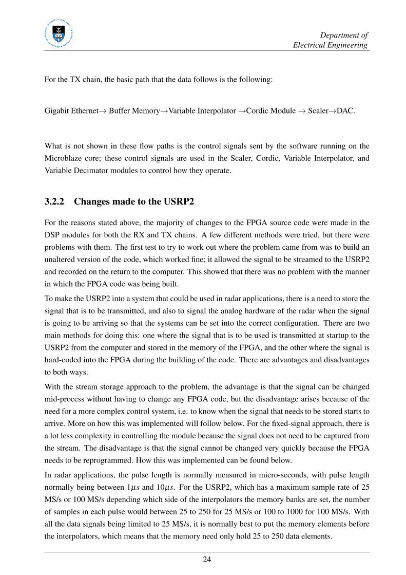
3.2.1 Data Flow Path . . . . . . . . . . . . . . . . . . . . . . . . . . . . . . . . . 23
3.2.2 Changes made to the USRP2 . . . . . . . . . . . . . . . . . . . . . . . . . . 24
3.3 Implementation Process . . . . . . . . . . . . . . . . . . . . . . . . . . . . . . . . . 28
4 Results 30
4.1 Streaming data . . . . . . . . . . . . . . . . . . . . . . . . . . . . . . . . . . . . . 30
4.2 Storing the Data . . . . . . . . . . . . . . . . . . . . . . . . . . . . . . . . . . . . . 31
4.3 What did not work . . . . . . . . . . . . . . . . . . . . . . . . . . . . . . . . . . . 33
5 Conclusions 37
A GNU Radio Setup 39
B CD content 41
C Sample FPGA Code 42
D Academic work done with the USRP2 49
Bibliography 51
v

List of Figures
1.1 USRP2 board with two daughter boards plugged in, BasicRX and BasicTX. . . . . . 3
2.1 A plot of two chirp signals, -250Hz to 250Hz, with noise, sampled at 1 kHz. . . . . 9
2.2 A plot of the output of a matched filter used on the signal from Figure 2.1 beingmatched to the chirp signal, sampled at 1 kHz. . . . . . . . . . . . . . . . . . . . . . 10
2.3 Computational types, rates, and storage in a generic radar signal and data processor.The GFLOPS and MFLOPS stand for billions and millions of Floating-Point Oper-ations Per Second. Richards et al. [111] . . . . . . . . . . . . . . . . . . . . . . . . 13
2.4 Data flow paths in the USRP2 . . . . . . . . . . . . . . . . . . . . . . . . . . . . . 14
3.1 This plot shows the effect of different bit counts. This is the FFT of a 50 MHz sinewave sampled at 1 GHz. . . . . . . . . . . . . . . . . . . . . . . . . . . . . . . . . 21
4.1 Plot of the returned signal when data is streamed from the computer, 25MHz band-width signal, sampled at 25MHz. . . . . . . . . . . . . . . . . . . . . . . . . . . . . 31
4.2 Plot of the same signal as in Figure 4.1, captured using an Agilent TechnologiesDSO5012A oscilloscope. . . . . . . . . . . . . . . . . . . . . . . . . . . . . . . . . 32
4.3 This plot shows a chirp with a bandwidth of 25 MHz that is 100 samples long and issampled at 100 MHz.. . . . . . . . . . . . . . . . . . . . . . . . . . . . . . . . . . . 33
4.4 This plot shows the PRI of the signal in Figure 4.3, with the PRF of 1 kHz. . . . . . . 34
4.5 A plot of the time domain of the returned signal, with a pulse length of 1µs. . . . . . 35
4.6 Plot of the output of the matched filter, for 25MHz chirp sampled at 25MHz with atotal of 25 samples in the pulse. . . . . . . . . . . . . . . . . . . . . . . . . . . . . . 35
4.7 Plot of two consecutive pulses, with a PRF of 1kHz and a PRI of 1ms. . . . . . . . . 36
vi

List of Tables
1.1 Table of the costs of the different boards. . . . . . . . . . . . . . . . . . . . . . . . . 2
2.1 The speeds of various types of connections, Debatty [37] . . . . . . . . . . . . . . . 11
3.1 The hardware differences between the FPGAs used in the USRP and USRP2, gnu[3], Xil [146], Alt [6] . . . . . . . . . . . . . . . . . . . . . . . . . . . . . . . . . . 18
3.2 Details on the ADC and DAC chips used in the USRP2. Lin [80]Ana [10] . . . . . . 19
vii

Nomenclature
ADC—Analog to Digital Converter, a system for converting analog signals to digital signals.
Bandwidth—The frequency width of a signal, measured from the lowest frequency component ofthe signal to the highest component.
Chirp—A signal with an increasing frequency over time.
CPU—Central Processing Unit, the main processing element of computer systems.
DAC—Digital to Analog Converter, a system for converting digital signals to analog signals.
Doppler frequency—A shift in the radio frequency of the return from a target or other object as aresult of the object’s radial motion relative to the radar.
FPGA—Field Programmable Gate Array.
GNU—GNU is the name for a super-set of projects, whose main goal is fully open software.
GPU—Graphic Processing Unit, the data processing element of a graphics card, currently beingused to perform complex computations.
OS—Operating System of a computer.
PRF—Pulse Repetition Frequency.
PRI—Pulse Repetition Interval.
Python—Python is a high-level scripting language.
Range—The radial distance from a radar to a target.
RF—Radio Frequency.
RX—Receiving
Synthetic Aperture Radar (SAR)—A signal-processing technique for improving the azimuth res-olution beyond the beam-width of the physical antenna actually used in the radar system. This isdone by synthesizing the equivalent of a very long side-looking array antenna.
Swath—The area on earth covered by the antenna signal.
SWIG—SWIG is an open source program that allows connections between C or C++ programs orlibraries with other scripting languages, such as Python.
TX—Transmission
USRP—Universal Software Radio Peripheral, an FPGA based RF front end for use with computers.
viii

Department ofElectrical Engineering
USRP2—Universal Software Radio Peripheral 2, the second generation FPGA based RF front endboard.
ix

Chapter 1
Introduction
Radars were first developed in the mid 1930’s in Britain for use in protecting Britain from the airattacks from the German Luftwaffe. At the same time, the first computers were also developed tobreak the German Enigma codes. The entire signal processing system on radar systems was doneusing analog equipment. This equipment was very specialised and very expensive. These radarswere very limited in how they were able to process the data, mainly being limited to thresholddetection of range and direction, and almost nothing else. Also one other problem with these typesof radars was that they needed a high-powered signal to get a usable signal-to-noise ratio. Page [97]
A lot of the higher level of data processing of radar was held back because of the lack of hardwarethat was able to do the needed processing. This all changed in the 1970’s with the developmentof digital processing systems with enough processing power to be able to handle the needed pro-cessing. With the change to digital processing, it became possible to implement more effective dataprocessing algorithms; the most notable of these being the Matched Filter. This type of filter is de-signed to give a very strong response when an identical signal is passed through it; at the same timeit rejects signals that are not correctly matched. These two factors together resulted in much lowerpower requirements being adequate to get the same level of performance. Richards et al. [111]
One of the main problems with radar systems designed between the 70’s and 90’s was that they wererelatively fixed in their functionality. If the functionality of the radar needed to be changed for anyoperational reason, it would take anything from a few hours to a few days. Also, another problemwith these radar systems is the high cost, which makes it impractical for third world countries toinstall radar systems to control their air space. With the advances in the last decade or so withregard to computer processing power, large amounts of the data processing that used to be done ondedicated digital hardware is moving to more general digital hardware. Debatty [37]
This new concept, called Software-Defined Radar (SDR), is a concept to make a complete radar justusing reprogrammable hardware. With the use of SDR systems it is possible reduce the cost of radarconsiderably, which makes it much more affordable for poorer countries. A key components of theseradar systems are Field Programmable Gate Arrays (FPGA), which allow implementation of high-
1

Department ofElectrical Engineering
speed data processing in a reconfigurable format. Debatty [37] This project will be investigating theuse of one of these FPGA as the data processing base for a radar system.
The main advantage of FPGAs over conventional data processing devices such as CPUs is that theyhave a very high level of process parallelism. This allows for effective implementation of manyof the basic radar data processing algorithms. The main processes done in most radar systems areMatched Filtering, Threshold, and Doppler Processing.
1.1 Hardware Chosen
One of the main goals of this project is to design a low-cost radar system for use in Africa where thereis not a large number of radar systems. To this end there was a need for a low cost processing systemfor the radar. For basic air traffic control there is not a need for large amounts of data processing, somodern computers can be used for a lot of the data processing and display. The only real problem isthat computers are not very good at handling low-level signal processing which is needed in a radarfront end.
To this end, a data capture board is needed. Current designs of these types of boards use FPGAsas their main processing units. There are a number of different board designs available, all withdifferent abilities and functionalities. This project was done a small budget; thus only hardwarecurrently in the possession of the group has been considered. There are four different pieces ofhardware that are currently available in the group; these are the USRP, the USRP2, the Rhino board,and the Roach board. All of these boards are FPGA-based processing boards. USRP and USRP2are FPGA only boards, whilst the Rhino and Roach have both FPGA and ARM processors on them.
Table 1.1: Table of the costs of the different boards.USRP USRP2 Rhino Roach
Cost $700 $1400 ( Has been discontinued) $1750 (Academic price) About R100 000
With regard to the performance and space for systems to be implemented, either the Rhino1 or theRoach would be the best choice. The main problem with these boards is that their availability is notthat high because of cost and limited run numbers. There has been a previous attempt to implementa radar system on the USRP board, but it was found that the hardware limitations did not allow fora working system to be run, this came from the fact that all the data processing needs to be done onthe computer it was attached to.
From the standard specification of the USRP2, it was believed that it would be able to handle thedata rate and data processing requirements. Also, the group already had some of these boards, sothere was no cost in using them. For this reason it was decided that the USRP2 would be the bestboard for the project.
1More information about this board can be found Simon Scott’s Masters Dissertation, Scott [119].
2

Department ofElectrical Engineering
1.2 Project Background
In 2001, work started on computer-controlled radio systems. This project was started under theGNU licence, and was called “GNU Radio”. The GNU Radio project set out to develop softwarethat would allow easy setting up of radio applications on a computer. It was originally written inPspectra but, in 2004, it was completely rewritten from the ground up in C++ and Python. TheDigital Signal Processing (DSP) is done by the C/C++ modules, because the C/C++ code is one ofthe most efficient programming languages, on both processing speed and memory use. Python isused to connect the high-level code blocks together because of the relatively low amount of dataprocessing that is needed to connect the blocks, and because it also allows easy implementation ofmulti-threading processing.
Figure 1.1: USRP2 board with two daughter boards plugged in, BasicRX and BasicTX.
Originally, GNU Radio used the sound cards of the computer to interact with the exterior worldbut, in 2004, Ettus Research LLC was founded. They designed and manufactured the “Univer-sal Software Radio Peripheral” (USRP) boards. The original USRP board has an Altera Field-Programmable Gate Array (FPGA) chip as its controller. With the addition of the USRP board tothe GNU Radio line up, high sampling rate systems were possible, mainly because the USRP boardhad a sampling rate of 64 MHz, compared to normal sound cards which only sample at 44 kHz.This speed limitation came from the processing speed of the FPGA chip and the fact that it used theUniversal Serial Bus (USB) 2.0 for its data transfer connection with the computer. In 2008, EttusResearch LLC brought out the USRP2 board. This system featured a much larger FPGA, and it useda Gigabit Ethernet connection to communicate with the computer. With these updates, the USRP2has a sampling rate of 100 MHz.
3

Department ofElectrical Engineering
1.3 Objectives of the Project
The objectives for this project are to investigate the use of the USRP2 board as a base processingunit for use in a low cost radar system. To this end evaluation of GNU Radio is planned to determineit ability to run radar systems, and the processing resources need for it handle such operations. Anevaluation of how the USRP2 FPGA handles data processing is also need to determine how dataflows through the board and if there is any means by which to move some of the data processingfrom the computer to the FPGA. Once all the evaluations are done then a Pulsed Radar System willbe implemented.
• Get GNU Radio to work so that it can be used to capture data.
• Determine the computer hardware needed to operate GNU Radio to do radar work effectively.
• Work out how the FPGA code is designed.
• Determine if the FPGA code can be changed easily.
• Implement a Pulsed Radar System using GNU Radio and the USRP2 board.
1.4 Scope and Limitations
The scope of this project is to implement a pulsed radar system on the USRP2 board. Because ofthe complexity of the USRP2 systems and the nature of the connection that is used over the GigabitEthernet, it was decided that GNU Radio was to be used to control and capture data off the USRP2board. It was also the hope for this project to alter the FPGA code to allow more functionality forthe radar system.
1.5 Document Outline
The layout of the remainder of this report:
In Chapter 2, the basic principles of SDR are discussed, as well as the main properties of GNURadio and the USRP2 board. This chapter focuses on the basics of SDR and the limitations comingfrom the different data processing systems, most notably the limitation of data transfer betweenprocessing systems, such as the CPU and FPGA processor, as well as the data rate at which theCPU-based processing can be done. It also contains an overview of GNU Radio and how to set it upfor use in radar applications.
Chapter 3 describes how the USRP2 FPGA code works and how it may be changed to get it toperform radar signal processing. It also shows the problems with the design of the USRP2 board andthe software running on it.
4

Department ofElectrical Engineering
Chapter 4 discusses the results obtained during experiments run using the USRP2 board. The USRP2can be run in both streaming and fixed storage mode, with stream storage not being possible becauseof the required placement of the storage modules after the DSP section. With a maximum instant-aneous bandwidth of 25 MHz, this limits the ability of a normal computer to be able to do real-timeapplications, but it can store the data for processing later without any problems.
Chapter 5 contains the conclusions and recommendations based on the results of the previous chapters.It was found that the USRP2 works correctly in a streaming mode where data is constantly beingsent from the computer to the USRP2. Attempts were made to change the FPGA code running onthe USRP2 to allow it to store signals on the board and thereby reduce the amount of processing thatthe computer needed to do. It is possible to make the system work in a fixed storage mode, but itis not possible to save streamed data. The suspected reason for this is the complexity in the controldone in the DSP section, which is very poorly documented. As a result, the USRP2 combined withGNU Radio is not a practical system for use in operational radar systems but it is passable as a basictest bench for radar hardware.
5

Chapter 2
Literature Review
2.1 Software Defined Radar
When radars were first developed, they were purely analog systems, which meant they were verylarge and complicated, and used very special and expensive components. As the processing powerof computers increased over time, they became more and more used but, until the development offast computers, they have only been used for very high-level processing after most, if not all, ofthe signal processing has been done. Only in the last decade or so, has the processing power ofcomputers increased to such a point that it is possible to implement most of the signal processing inthe digital processor. At present, it is not possible to implement a fully functional radar system withjust digital systems, for the following reasons:
• The limits on operational frequencies of Digital to Analogue Converters (DACs) and Analogueto Digital Converters (ADCs), compared to the required frequency for radar applications. MostADCs operate below 1 GHz, whereas radar systems operate between 1 GHz and 40 GHz. Thismeans that the systems need the use of frequency converters. These are normally implementedby multiplying the signal by a constant-frequency sine wave at the desired frequency.
• The power output of most DACs is in the mW range, which makes them impractical for radarapplications, requiring power amplification.
• Antennae only operate in limited frequency ranges so they have to be replaced if the operationfrequency is changed by a large enough margin.
For the reasons stated above, it is not possible to make a purely SDR system, but it is possible toimplement much of the signal processing in digital form. This in turn allows for much more complextypes of detectors to be implemented, and for much more complex signal processing functions to berun.
6

Department ofElectrical Engineering
2.1.1 Data Processing Method
The type of system being implemented is a pulsed radar system, which means that the radar transmitsa signal intermittently. Consequently, for most of the time, the radar is not transmitting. The rate atwhich the radar transmits its signal is known as the Pulse Repetition Frequency (PRF).
Matched Filters
In radar systems, the main interest is to know if there is a target of interest and what its range isfrom the radar. The antenna picks up all the signals in its bandwidth, so determining what is a targetand what is noise is very difficult with just the raw data. With radars, we know what signal wesent out, so we can filter for this particular signal in the received data. This is done with a functioncalled a ‘Matched Filter’. It should be noted that the Matched Filter has different forms dependingon what type of hardware it is run on. The maths for Matched Filters is shown below. All of thefollowing maths is done in discrete time; if it was in continuous time, all the summations wouldbecome integrations.
y[n] = tx[n]∗ rx[n] (2.1)
In Eq 2.1, y[n] is the output of the matched filter, tx[n] is the transmitted signal, rx[n] is the receivedsignal, and ∗denotes the convolution operation. It should be noted that the rx signal is a lot largerthan the tx signal, because the tx signal, is only the length of the sent signal, which is normallyabout 100 µs long, and it has no output for the rest of the time. This equation is implemented in thefollowing way.
y[n] =∞
∑k=0
rx[n− k]tx[k] (2.2)
As can be seen in Eq 2.2, it requires summation over all of the signals, which makes it impossibleto implement, but this can be improved by windowing the transmitted signals. Thus, Eq 2.2 can berewritten as shown in Eq 2.3, were the tx signal has a length N.
y[n] =N−1
∑k=0
rx[n− k]tx[k] (2.3)
This still gives a problem because, to produce a single output it requires N multipliers and N −1 additions and, since these values are normally floating-point complex numbers, it becomes anexpensive method for implementing the matched filter. It can be made less computationally intensive
7

Department ofElectrical Engineering
by the use of Fourier transforms because the Fourier transform converts the convolution operationinto a multiplication operation. It is implemented in discrete time with the use of the Fast FourierTransform (FFT).
Y [ω] = FFT (rx[n]∗ tx[n]) (2.4)
= RX [ω]T X [ω]
y[n] = FFT−1(Y [ω])
= FFT−1(RX [ω]T X [ω])
As can be seen in Eq 2.4, the use of Fourier transforms has greatly reduced the amount of computa-tions. The Fourier transform of the tx[n]signal can be pre-worked and stored beforehand, thereby de-creasing the amount of processing needed. The Fourier method works well on sequential processorslike those used in computers but, for implementation on an FPGA, it is more resource-effective touse the method shown in Eq 2.3. The reason for this is that an FPGA is able to handle many differentoperations during each clock cycle, and therefore it can do all of the multiplications and additionsneeded to generate a single data point in one clock cycle. It also uses less memory because it onlyneeds to hold 2N samples.
Figures 2.1 and 2.2, show the effect of Matched Filtering. The two plots were generated in Matlabusing the chirp generator function and a random number generator.
Figure 2.1, shows a plot of a signal containing two chirp signals both with a bandwidth of 500 Hzalong with noise. A chirp is a signal with linearly increasing frequency with time, very often usedwith radar because it gives a large bandwidth and does not normally occur in nature.
As can be seen in Figure 2.2, the matched filter reduced the width of the targets down to a singlepoint and improved the signal to noise ratio (SNR). Richards et al. [111]
Threshold Detection
After matched filtering, the signal can be put through a threshold detector, which allows the detectionof targets of interest. There are many different detection algorithms but they all have the same basicgoals: to increase the chances of detecting a target and at the same time to decrease the chancesof detecting false targets. Most radars have the requirement of having a probability of detection ofover 0.9 with a probability of false alarm below 10−4. But, to achieve these requirements, there isa need for high SNR; normally an SNR of over 10dB is needed. There are methods to improve the
8

Department ofElectrical Engineering
Figure 2.1: A plot of two chirp signals, -250Hz to 250Hz, with noise, sampled at 1 kHz.
probability of detection and false alarms by implementing m-of-n, which is where a target is onlydeclared a target if there are m or more detections in n sample sets. Richards et al. [111]
Doppler Processing
Another method for improving the chances of detecting a target is to perform Doppler processingof the data before the data is passed through a threshold detector. However, to perform Dopplerprocessing, the phase of the returned signals is needed, for which reason the In-phase and Quadratorare needed for each sample. The Doppler process allows the system to know the range and the speedof the target. This helps to improve the SNR because most clutter, returns of non-interest targets, isnormally stationary or relatively slow moving.
If the targets of interest are aeroplanes for example, they have a speed that is much higher thanthe speed of any clutter objects, so they are moved away from the background clutter. The normaloutput of a Doppler process is a 2D data set with intensity at every range and speed point underconsideration. This output is often referred to as a Range Doppler Plot (RDP). To perform theDoppler processing, an independent FFT is performed for each range bin, because of which it isonly possible to do Doppler processing when the captured signal has both its In-phase and Quadratorvalues sampled at the same time. Richards et al. [111]
Whilst relatively little memory is needed for the implementation of the matched filter and basicthreshold detections, the Doppler processing needs to remember large numbers of sample sets and
9

Department ofElectrical Engineering
Figure 2.2: A plot of the output of a matched filter used on the signal from Figure 2.1 being matchedto the chirp signal, sampled at 1 kHz.
therefore this is not often implemented on FPGAs because of their limited memory capacity. Forexample, let us consider the case of a radar that needs to observe a range from 5km to 50km, and thesignal returns are sampled at 25 MS/s. This means that, for each pulse of the radar, there are 3 750samples that need to be stored, but there is also a need for 50 pulses to be stored to do the Dopplerprocessing. This means that there are 187 500 samples to be stored before the Doppler process canbe run, and the same number of samples from the output of the Doppler process must also be stored.Furthermore, all the data points are complex numbers.
2.1.2 Current Thinking in Software Defined Radar Systems
When implementing a Software Defined Radar (SDR) system, there is a need for high speed ADCsand DACs, which means that a periphery board is needed. Most of the modern types of boards usean FPGA to control and operate the ADCs and DACs. There are a few ways to connect these devicesto a computer, as shown in Table 2.1:
The data shown in the sample speed column of Table 2.1 shows the sample transfer rate of a complexsignal with the real and complex signal elements both being 16 bits long.
Currently, thinking around SDRs is split into two different sections - FPGA processing, or computer-
10

Department ofElectrical Engineering
Table 2.1: The speeds of various types of connections, Debatty [37]Connection Types Connection Speed (Mbit/s) Sample Speed (MS/s)(32bit/s)
PCIe x8 16000 500(e)SATA 2400 75PCIe x1 2000 62.5
PCI 1067 33.34Gigabit Ethernet 1000 31.25
USB2.0 480 15Fast Ethernet 100 3.125
based processing:
• With FPGA processing, almost all of the processing is done on the FPGA, with the computeronly handling the processing needed to display the radar plots.
• The other approach is to use the computer to do most of the data processing, with the FPGAboard only handing the signal capture and perhaps a small amount of signal processing.
Computer-Based Processing
With the increase in processing power over the last decade, computers have become more able tohandle the processing needs for radar applications in real time. If the radar system needs to runin real time, there are certain limits that are imposed on the system by the processing speed of acomputer.
Let us assume that the captured data is being transferred to the computer over a Gigabit Ethernetconnection, as used with the USRP2 board, and it is bringing in a 32-bit complex number. Then, asample transfer speed of 31.25 Million Samples per second (MS/s) over the Ethernet connection isthe maximum possible transfer speed, as shown in Table 2.1. This means that each new sample has96 clock cycles in which to be processed. This assumes that the processor is running at 3GHz andthere are no other operations needing to be done by the operating system on that processor. Withonly 96 clock cycles between samples, there is not much time to perform the number of complexoperations needed for a real-time radar system. This problem can be mitigated somewhat withcurrent multi-core processors since these have a maximum of eight cores, which would theoreticallygive eight times the processing power. However, this is not the case in practice; with an increase inthe number of cores, there is also an increase in the complexity of the control operations. Also, theOperating Systems (OS) need to be running on the same set of processors. With these two elementsjoined together, the true speed-up would be only around 7 to 7.5 fold.
It is possible to use modern graphic cards to do some of the data processing. These types of pro-cessors are normally called Graphic Processing Units (GPU), Jimmy Pettersson and Ian Wainwright
11

Department ofElectrical Engineering
[69]. The main advantage given by a GPU in radar data processing is that it is very parallel inits data processing architecture, which allows it to do the large numbers of calculations needed forradar very quickly. With GPUs being originally designed for computer graphic rendering, they havea large number of floating point processing units, which is exactly what is required for high-levelradar data processing. There are limits to how GPUs can be used because of current memory archi-tecture. Also, for this project, all of the processing on the computer was done offline, so a GPU wasnot used because there were no time constraints for data processing.
With most computers’ OS being non-real-time systems, splitting the operations of one module overmultiple processors is very difficult because of the lack of guaranteed timing between the processors.This becomes a problem when working at very high sampling rates were any small change to pro-cessing time has an effect on the processing of the following signal. This problem can be lessened tosome degree by the use of a Real-Time Operating System (RTOS), by allowing the fixing of dead-line finishing times for the processor, but it does not remove the problem completely. To implementan RTOS is not as simple as just buying one off the shelf; it takes deep understanding of how theprocesses have to run, Mercer and Tokuda [86]. Because of the complexities involved in setting upan RTOS, it was not part of the scope of this project.
FPGA Processing
The first commercially viable FPGA was produced 1985 by Xilinx Clarke [33], and had about 9000gates. Since then, the technology has been growing continuously; modern chips have about 2000000gates. One of the main reasons why FPGAs have become so popular in recent years for radar andsignal processing is their inherently parallel nature.
Unlike the situation with a multi-core die, it is possible to implement very fine-grained timing withinan FPGA chip, allowing multiple modules to work quickly and accurately together. Most FPGAprograms are divided up into small modules, all of which run at the same time on the FPGA becausethey are physically independent sections of the FPGA chip. Also, the elements inside each moduleare running at the same time, allowing for very high-speed computation. This is very useful for low-level signal processing, such as filtering and detection, which reduces the required sampling rate ofdata.
There are a few problems with FPGAs; they are hard to program because of the complexity involvedin making sure that all the modules talk together correctly and do what they are meant to do, andthey have limited processing resources; mainly the number of multiplication units and the amountof memory, so these place constraints on the complexity of systems implemented on the FPGA.
Figure 2.3 shows the amount of processing and memory needed for the main stages of a simple radarapplication. It is not correct for all the different types of radar systems; it is meant only to give an
12

Department ofElectrical Engineering
Data Processing
Data
Independent
Processing
Data
Dependent
Processing
Mission-Level
Processing
100s+ GFLOPS
1s-10s MBytes
10s-100s GFLOPS
10s-100s MBytes
10s-100s MFLOPS
100s+ MBytes
Radar
DateTo Displays
& Comm
Signal Processing
Figure 2.3: Computational types, rates, and storage in a generic radar signal and data processor. TheGFLOPS and MFLOPS stand for billions and millions of Floating-Point Operations Per Second.Richards et al. [111]
overview of the basic requirements needed in terms of data processing for a radar system. “Data-independent processing” refers to the use of fixed-function methods on the data, such as matchedfiltering and pulse compression. These methods are based on the principle of data streaming struc-tures. Also, these methods can be implemented using fixed-point numbers, which allows for effectiveimplementation on FPGAs.
When the data is finished in the data-independent processing section of the system, it is movedon to the data-dependent processing section. In this section, information in the data is used todetermine how the data is to be processed. An example of this type of processing is “constant falsealarm rate” (CFAR) processing, were the main aim is to get the highest probability of detectionfor a given probability of false alarm. There are a few different methods for implementing thesetypes of systems, but they all need large numbers of samples to be stored at any one time. Thisdata processing is normally done on FPGAs because of their ability to handle large amounts ofsimultaneous processes, but these systems need chips designed to have high memory access abilities.This is one area where the chip in the USRP2 does not have the basic architecture to achieve thisfunctionality. No CFAR algorithm was implemented in this project because it was outside the scopeof the project.
The final type of processing before display is mission-level processing. This level of processingnormally involves very complex computational operations, such as matrix inversion. An example ofthis is the process used in tracking algorithms that use the data to predict where the target will be,then check to see if the prediction is correct, and then readjust the process to give better results nexttime. These types of algorithms are normally difficult to implement on an FPGA because of theirrecursive nature and the large memory needed to implement them. The redeeming feature of thesetypes of algorithms is that they normally have much lower processing needs, as shown in Figure 2.3.
13

Department ofElectrical Engineering
2.2 USRP2
As stated in Section 1.1, the USRP2 was chosen since the group had a few available for use inthis project. The USRP2 was originally designed for use in amateur radio systems but there wasa hope that it had the ability to handle basic radar applications. The USRP2 consists of sevenmajor components namely the FPGA, RAM, ADC, DAC, Gigabit Ethernet, Programmer, and CardMemory. The FPGA is a Xilinx Spartan 3 chip, clocked to 100 MHz. The default build for theUSRP2 has an emulated CPU running on the FPGA to handle the control of the system. The ADC isa 14-bit 100 MS/s chip, and the DAC is a 16-bit 400 MS/s chip. The programmer handles loading ofthe image onto the FPGA at start up and also passes the instructions for the emulated CPU. It readsall of this information off the card memory. The card memory can be written after the system hasstarted up. The ram is 9 Mbit (512K x 18) single read per clock.
The logic layout of the main elements in the USRP2 is shown in the following Figure 2.4.
�
����
DAC
FPGA
Gigabit Ethernet
Programmer
Card Memory
RAM
Figure 2.4: Data flow paths in the USRP2
In the original design of the USRP2, the FPGA only handled very basic signal processing logic:adding and removing the dc offset need by the ADC and DAC, and decimation and interpolation ofthe data streams being sent between the Ethernet interface and the ADC and DAC.
14

Department ofElectrical Engineering
2.3 GNU Radio
As the name suggests, GNU radio was designed as a software-defined radio application set. Toachieve this, it was mostly written in C/C++ to allow effective use of processing resources. To allowit to do many different types of jobs without any rewriting of the code, all the processing is spilt upinto small processing modules, such as a filter, modulators, and type converters. Connecting thesemodules in C/C++ would be a fiercely complicated job, and also the program would have to berecompiled each time someone wanted to change how something in the program ran. To get aroundthat, GNU radio uses Python to connect the modules together because of the small amount of dataprocessing that would have to be done in the Python code. To allow the Python code to call theC/C++ modules as if they were normal Python functions, the C/C++ modules are wrapped insideSWIG (Simplified Wrapper and Interface Generator) code. gnu [3]
With GNU Radio being designed for radio applications, it cannot really handle high data processingrates because most of the data processing is done on the computer. This is acceptable for radio workbecause most radio systems work in a bandwidth range from tens to hundreds of kHz, which allowsmost modern processors to keep up with the data processing requirements of the signal. However,for radar applications, there is a need to get as much signal bandwidth as possible and, to achievethis, the systems need to be able to handle high sampling speeds, normally in the range of a fewMHz to 100s of MHz. With data rates this high, it is not possible to do the entire signal processingon computers.
We cannot just wait for the next few generations of processors to come onto the market becausethe processing speed of processors has not really increased in the last few years. Although Moore’sLaw is still going strong, with the number of transistors on a chip doubling about every 18 months,this increase in the number of transistors has only allowed processor chips to gain more independentprocessors on each chip. Current generation processor chips have up to 8 physical processing dieson them, AMD [8]. Because GNU radio uses a modular processing design, it very easily implementsmulti-threaded code, were the parallelism is done at the module level. This is very high-level par-allelism. For real-time application, each module needs to finish all its work on a single signal pointbefore the next one arrives and there are normally about 100 clock cycles between signals when thesampling rate is around 10 MS/s.
For this project, GNU radio was only being used to control a USRP2 board and to store the receiveddata onto the computer for processing later, which means that it does very little processing duringthe sending and receiving of the signal. For instructions on how to setup GNU Radio for use in radarapplications, please refer to Appendix A.
15

Department ofElectrical Engineering
2.4 Academic work done with the USRP2
In this section an overview is given of all currently available academic papers that mention USRP2and FPGA. These documents were found with the use of Google Scholar, with the key words being“USRP2” and “FPGA”. It generated a list of 167 documents of which some were copies and somewere not in English, so the number viewed is 137.
Of the 137 papers that were considered, 56 of them only mentioned the USRP2 and did no work withit. Most of the time, the USRP2 is only mentioned as a system for future work. Another 79 papersdid use the USRP2 as part or whole of the system being considered. All of these papers imply thatthey are using the USRP2 unaltered, i.e. streaming the data to and from the USRP2. Also, almostall of these papers are telecommunication papers. A full list of which papers were looked at can befound in Appendix D.
Of all of these papers, only two state that they had changed the code running on the FPGA. Negnevit-sky [92], is a final year undergrad project, the student failed to get the alterations that were made tothe USRP2 to work. This work alone would not count for much but for the fact that another report,this time from three Masters students, Pucci et al. [105], also failed to get their changes workingwith the board. From these reports, a trend is starting to form, which points to the impracticality ofchanging the USRP2 operating code.
2.5 Methodology
The objective for this project was to change the USRP2 into a low-frequency RF device to helpwith future projects in the group. To this end, there was a need to be able to transmit signals fromthe USRP2. These signals could either be streamed from a computer or stored on the FPGA. Themethodology used in this project is as follows:
• First a review of the literature on the USRP2 and GNU Radio was done. From this, a basicworking understanding was developed of how GNU Radio works and, to some degree, howUSRP2 works.
• The first set of tests with USRP2 and GNU Radio were to check that they were all workingcorrectly. In these tests, no changes were made to how USRP2 works.
• Alterations to the USRP2 FPGA code were made to allow it store signals on the board, seeChapter 3. Two alterations were evaluated for storing the data on the FPGA, these being hardcoding of the signal onto the board, and the storage location of the data being streamed tothe board. To reduce the amount of processing that the computer needs to do to the receivedsignal, a matched filter was written to work on the FPGA.
16

Department ofElectrical Engineering
• The experiments run with the system involved outputting the signal to an oscilloscope orfeeding the signal straight back into the board itself. Also, the system was tested with theradar front end designed by Stacey Rukezo, Rukezo [115], for her MSc (Eng).
• The experiments were done, plots were saved from the oscilloscope, and the looped-back datawas saved and examined in Matlab. These results can be found in Chapter 4.
17

Chapter 3
USRP2 FPGA
The USRP2 FPGA is the second generation of purpose-built signal capture boards for GNU Radio.It was designed to increase the bandwidth available to GNU radio programs. In this chapter, thehardware and FPGA code of the USRP2 board will be examined with respect to its use in a radarapplication.
3.1 USRP2 Hardware
The USRP2 board is an FPGA-based data capture board designed by Ettus Research LLC that wasfirst produced in 2008 and was discontinued in 2011. The design for the USRP2 board is verydifferent from that of the USRP board. These differences come in the form of a much larger FPGAdie, the use of Gigabit Ethernet rather than USB2.0, and the use of an SD card memory to load theFPGA code onto the FPGA at start up, whereas the USRP had to be written to from the PC at startup.
Table 3.1: The hardware differences between the FPGAs used in the USRP and USRP2, gnu [3], Xil[146], Alt [6]
USRP2 USRPFPGA Type Xilinx Spartan 3 Altera Cyclone
FPGA clock speed 100 MHZ 64 MHzLogic Elements 46080 12060
Hardware multipliers 40 NoneConnection types Gigabit Ethernet USB 2.0
DACs One Double Channel 16 bit 400 MS/s Two Double Channel 14 bit 128 MS/sADCs One Double Channel 14 bit 100 MS/s Two Double Channel 12 bit 64 MS/s
(FPGA limited)
18

Department ofElectrical Engineering
The clock on the USRP2 receives its timing from an Analog Devices AD9510 1.2 GHz Clock Dis-tribution IC, which is clocking at 100MHz; with a phase noise in the region of -140 dBc/Hz Ana[9]. It is also possible to sink the systems to a 10MHz external reference clock. Along with this, it ispossible to pass it a 1 Pulse Per Second (PPS) signal used to get the time stamping between multiplesystems to match.
As can be seen in Table 3.1, the USRP2 has much more processing power than the USRP, but thisdoes not give the full picture of the two systems; the other part of the system is the code running onthe FPGA, and this will be discussed further in the Section 3.2.
When hardware is being considered for use in radar applications, there are few major things thatneed to be considered:
• The sampling rate, because it affects the bandwidth of the signal that can be transmitted andreceived.
• The bit accuracy of the signal when in digital form, which affects the noise level in the signal.
• The transfer speed to the computer system and the data capture board.
• The processing resources in the FPGA.
3.1.1 Sampling Chips
The USRP2 uses fixed on board converter chips; the LTC2284 chip is used as the ADC and theAD9777 chip is used as the DAC. The following Table 3.2, shows the specification of the two chips.
Table 3.2: Details on the ADC and DAC chips used in the USRP2. Lin [80]Ana [10]LTC2284 AD9777
Type ADC DACBit Width 14 bit 16 bit
Sampling Rate 105 MS/s 160MS/s / 400MS/sSNR 72.4dB 75dB
Crosstalk -110dB Not GivenImpedance Mismatch Not Given Not Given
Dynamic Range 78.26dB 90.30dB
By the Nyquist sampling theorem, if the signal is only being recorded by its In-phase component thenthe sampling rate needs to be twice the bandwidth of the signal. If both the In-phase and Quadratorare being sampled, then it only needs to sample at the same rate as the bandwidth of the signal.Therefore, with a sampling rate of 100 MS/s on the USRP2 with it sampling both the In-phase andQuadrator signals, it would appear to be possible in theory to have a signal with a bandwidth of 100MHz, but this is not possible because the signal is decimated by a factor of 4 on the FPGA, which
19

Department ofElectrical Engineering
will be discussed further in Section 3.2. Consequently, the effective sampling rate that the systemhas an instantaneous bandwidth of 25 MHz, which is above average for the bandwidth of signalsbeing used in radar systems these days.
One of the problem areas with radars is their need for a large dynamic range because of the effectsof target reflection cross section, and the effect that range has through its R4nature. Consequently,a radar needs a dynamic range of about 40 to 80 dB. As can be seen in Table 3.2,the ADC on theUSRP2 has a dynamic range of 78 dB, which is good enough for all but the most extreme situations.
The effect of sampling bit count is not as plain as the effect of the sampling rate, but it none theless plays a very important role on the quality of the data received. A higher bit count allowsdifferentiation of signal levels that are very similar. This comes from the quantization effect ofdigital conversions. It becomes important when implementing threshold systems.
Figure 3.1, shows the effect of different bit counts when sampling a signal. The setup is as follows:a single 50 MHz sine wave is sampled at 1 GHz. The red information shows the effect of only beingable to detect if the signal is high or low. This number of bits is completely impractical for use in anysystem because there is no way to tell large sections of the signal apart. In this figure, bit counts of 8or greater give very similar results. Increasing the bit resolution even further gives better resolutionbetween small variations, and also reduces the amount of squareness of the signal, thus reducing thelevel of square’s frequency components.
There are limits to the amount of processing that can be done on an FPGA before the data needsto be transferred to a computer. There are a few ways to do the transferring of the data, and thesecan be seen in Table 2.1. Not only does the transfer speed affect the system, but it also affects theamount of processing resources that the system needs to run the radar.
There are two ways of doing data processing: online and offline data processing. Online processingis done when the information is needed right away, which is the case in most radar systems. Offlinedata processing is processing at some time after the data has been captured. This is normally thecase in research and development of radar systems where different processing methods are beingtested. For this project, offline processing has been used; the computer has only been used to recordthe data.
With online processing, a two main system parameters need to be consider. The first is the sampleset length, and the other is the PRF of the system, because this affects how much time is availablefor processing the current data set before the next one needs to be processed. Also, there is a need tochoose which type of data is being sent to the computer. This is mostly dependent on the processingability of the FPGA. It can be anything from the raw data to the target’s position and speed anddirection. With raw data, all that the FPGA has done is to capture the returned signal and there mayhave been some low-level signal processing done on the data, but the FPGA has not attempted toidentify targets in the data. This is the largest amount of data that any system can send becauseeverything is sent the computer to be processed.
20

Department ofElectrical Engineering
Figure 3.1: This plot shows the effect of different bit counts. This is the FFT of a 50 MHz sine wavesampled at 1 GHz.
A few things that need to be considered with FPGAs:
• The amount of logic elements that the FPGA has, because this affects how much data pro-cessing can be done on the system.
• The number of hardware multipliers, because this affects how much signal processing can bedone on the FPGA.
• The amount of memory the FPGA has and how quickly it can be accessed by the FPGA.
FPGAs are very good at doing signal processing as long as it can be done in fixed point. The onlyproblem with fixed point numbers is that their bit size is directly proportional to the size of thenumber being stored; this is a problem when there is a need to multiply multiple fixed point numberstogether, because the number of bits need to be increased with each multiplication. The solution tothis problem is to use floating point numbers because these are exponential numbers, which meansthey have a very large dynamic range over which they interact. Flo [2] The only problem with
21

Department ofElectrical Engineering
floating point numbers is the complexity of the hardware needed to implement them; this leads todesigns on FPGAs using fixed point designs as much as possible.
3.1.2 Network Interface
The USRP2 uses a Gigabit Ethernet connection to connect the board to a computer. This allows fora more effective data transfer between the board and the computer than was achieved on the USRPboard, which was USB 2.0. The switch from USB 2.0 to Gigabit Ethernet allows for a higher datatransfer rate as well as full duplex data transfer. The problem with the version of the code that I wasworking with was that it only had raw Ethernet implemented. The fact that the system is transmittingdata in raw format is not a problem for streaming continuous low-bandwidth signals such as thoseused in radio applications for which the board was designed. With the use of raw Ethernet, it is itis only possible to connect the board directly into a computer and not be able to pass it through aswitch because of the lack of handling information in the stream. gnu [3]
In versions of the code released after the end of this project, the developers implemented a TCP/IP1
stack on the board. The lack of a TCP/IP system makes programming any program to interpret datafrom the board difficult because the program has to handle all of the data being sent from the boardeven if there is no real information being sent.
The TCP/IP stack was not implemented as part of this project because it would give no direct im-provement for the handling of data with the low-level signal processing that was attempted in thisproject, namely a Matched Filter. The amount of data produced from a Matched Filter is the same asthe raw data because the filter is only increasing the strength of a given signal. Only something suchas a thresholding function would reduce the amount of data that needs to be sent to the computer.For this project, it was decided that a Matched Filter would be enough and, since it did not have tobe able to run in real time; implementation of a TCP/IP stack was not needed.
3.2 USRP2 Code
There are two sets of code that run on the USRP2 FPGA. The first is the FPGA code itself, and thesecond is the C++ code that is run on the emulated CPU that runs on the FPGA. The emulated CPUis the Xilinx Microblaze IP core that Xilinx allows free use of, but is not open source. This was doneto allow some alteration of how the board works without having to rebuild the FPGA design becausemost people do not know how to program FPGAs, and rebuilding the design can easily take an houror more on most computers.
Also, there are limits to what can be done with the free version of the Xilinx ISE program, and thecost of the commercial version is too high for most people to afford for a program that they will not
1More information on TCP/IP can be found at http://en.wikipedia.org/wiki/TCP/IP_model
22

Department ofElectrical Engineering
use very often. A change between the USRP and USRP2 is how much the base code of USRP2 hasgrown from the USRP; all of the code for the USRP came to 3 megabytes, whilst for the USRP2 itcame to 13 megabytes; these are before the project files are made.
It should also be noted that very little exists in the way of documentation, with most people sayingthat the code is the documentation. Examples of how little commenting exists in the code can beseen in Appendix C, which shows the main DSP module TX chain.
The main sections of code from the FPGA that were examined and attempted to be altered were theDSP modules for the RX and TX chains. This was done because they give the closest set of modulesto the analog hardware. The RX DSP module does several things to the signal. First, it removes theDC offset from the ADC, and it decimates the signal by a factor of 4 or more. This gives a maximumdata rate of 25 MS/s and less, depending on the settings passed to the module from the Microblazecore. The signal is scaled by a scaling factor set by the Microblaze core. Finally it rounds downthe signal to 16 bits for each channel. Some of these functions are done with Xilinx’s IP cores,but most are custom-written code. The one module that is very useful for signal processing on theFPGA is the round down module. This is because it mathematically correctly rounds down a twoscomplement number very efficiently.
The TX DSP module does a lot less than the RX module because all it has to do is to interpolatethe incoming signal to get it up to 100 MS/s. There are only two settings for the interpolation; it iseither a factor of 4 or more, again set by control signals sent by the Microblaze core. The signal isalso scaled by a scaling factor that is set by the Microblaze core. The output of the multiplier is 36bits, of which only bits from 28 to 13 are sent to the DAC.
3.2.1 Data Flow Path
The USRP2 has two data flow paths, one for the RX chain and one for the TX chain. For the RXchain, the basic path that the data follows is the following:
ADC→DC Offset Remover→Scaler→Cordic Module→Fixed Decimator→Rounder→VariableDecimator→Rounder→ Buffer Memory→ Gigabit Ethernet.
The main modules of interest in this chain are the Fixed Decimator and the Variable Decimator; theFixed Decimator always decimates the signal by a factor of 4, whilst the Variable Decimator is setby signals transmitted to the USRP2 at start up. For the test done for this project, the decimationrate was set at 4, which meant that only the fixed decimator was used. This was to allow the greatestinstantaneous bandwidth possible for testing as well as to reduce the complexity of the processingchain.
23
Department ofElectrical Engineering
For the TX chain, the basic path that the data follows is the following:
Gigabit Ethernet→ Buffer Memory→Variable Interpolator→Cordic Module→ Scaler→DAC.
What is not shown in these flow paths is the control signals sent by the software running on theMicroblaze core; these control signals are used in the Scaler, Cordic, Variable Interpolator, andVariable Decimator modules to control how they operate.
3.2.2 Changes made to the USRP2
For the reasons stated above, the majority of changes to the FPGA source code were made in theDSP modules for both the RX and TX chains. A few different methods were tried, but there wereproblems with them. The first test to try to work out where the problem came from was to build anunaltered version of the code, which worked fine; it allowed the signal to be streamed to the USRP2and recorded on the return to the computer. This showed that there was no problem with the mannerin which the FPGA code was being built.
To make the USRP2 into a system that could be used in radar applications, there is a need to store thesignal that is to be transmitted, and also to signal the analog hardware of the radar when the signalis going to be arriving so that the systems can be set into the correct configuration. There are twomain methods for doing this: one where the signal that is to be used is transmitted at startup to theUSRP2 from the computer and stored in the memory of the FPGA, and the other where the signal ishard-coded into the FPGA during the building of the code. There are advantages and disadvantagesto both ways.
With the stream storage approach to the problem, the advantage is that the signal can be changedmid-process without having to change any FPGA code, but the disadvantage arises because of theneed for a more complex control system, i.e. to know when the signal that needs to be stored starts toarrive. More on how this was implemented will follow below. For the fixed-signal approach, there isa lot less complexity in controlling the module because the signal does not need to be captured fromthe stream. The disadvantage is that the signal cannot be changed very quickly because the FPGAneeds to be reprogrammed. How this was implemented can be found below.
In radar applications, the pulse length is normally measured in micro-seconds, with pulse lengthnormally being between 1µs and 10µs. For the USRP2, which has a maximum sample rate of 25MS/s or 100 MS/s depending which side of the interpolators the memory banks are set, the numberof samples in each pulse would between 25 to 250 for 25 MS/s or 100 to 1000 for 100 MS/s. Withall the data signals being limited to 25 MS/s, it is normally best to put the memory elements beforethe interpolators, which means that the memory need only hold 25 to 250 data elements.
24

Department ofElectrical Engineering
If the radar system only has a single antenna, the longer the pulse is the larger the blind range is.For a 1µs pulse, the blind range would be 300m. This means that any targets in the blind rangewould not be detected because the RX chain needs to be turned off to protect it from the high poweroutput of the TX chain. This problem can be overcome to some degree by having two antennas thatare shielded from each other such that there is very little direct cross talk between them. With twoantennas, the system can be run in continuous wave form; the signal being changed all the time sothere are no repeats.
Another important variable for a radar system is the frequency in which the pulse is repeated, notedas Pulse Repetition Frequency (PRF) or its inverse, Pulse Repetition Interval (PRI). The choice ofPRF has a large effect on the radar’s maximum range and Doppler unambiguous velocity. The lowerthe PRF the longer the range, but the slower the unambiguous velocity is. The higher the PRF, theshorter the range but the faster the unambiguous velocity is. For this project, there is no fixed designlimit on what the PRF could be, because the project is intended to be the starting point for any futurework on the USRP2 board for radar, and therefore it is designed to very flexible on what it canhandle. For testing, a PRF of 1 kHz was used, but that could be changed to anything that user wants.
Flexible Signal System
This system type allows signals to be sent to the USRP2 whilst it is running. This is done by usingmemory elements: either Block RAM (BRAM) or Verilog reg elements. BRAM is a basic IP core,free distributed for all current Xilinx FPGA systems. It allows access to small amounts of RAM.BRAM is a two-port memory, which means that it can be read from or written to with two differentaddresses.
There are limits to how large any given BRAM element can be. The limit is normally a few kilobytes,but multiple units can be connected to allow for larger memory elements. With the FPGA used inthe USRP2, each BRAM module has space for 512 elements with a width of 32 bits. The othertype of memory is the reg element, which is the basic programming element in Verilog, which usesprogramming slices to form memory elements. This uses up more of the physical hardware of theFPGA but, for very small amounts of storage, it can be more effective than BRAM modules becausethere is only a limited number of BRAM modules on an FPGA.
For the system to be implemented without a very complex control system, a fixed number of sampleelements needs to be used. For example, if the user wants a system that sends a pulse every secondwith a 1µs pulse length, then the FPGA needs to store 25 samples and know to transmit 24999975samples of nothing. That means that, at start up, the FPGA needs to store the first 25 samples ofthe signal being sent from the computer. However, there is no telling if the first 25 that the FPGAprocesses are the signal that the user wanted to use for the signal, so there needs to be a codeembedded in the signal sent by the computer to tell the FPGA when to start recording the data. Forreliability, the control signal should be more than one sample long, and the control signal should be
25

Department ofElectrical Engineering
something that is very unlikely to occur normally in the data.
When the system detects the control signal, it starts recording the signal and keeps going until itfills the memory allocated, after which no signals are stored until it receives the control signal again.After the signal has been stored, it needs to be read from memory and transmitted. After the shortpulse is sent to the FPGA, it needs to keep sending zeros so the DAC does not transmit anything.Another option is to put the DAC into a sleep mode, in which only the DAC output current is turnedoff; this allows the chip to come back to full operation as soon as it is needed, Ana [10]. This is doneuntil the next pulse is required to be sent.
Fixed Signal System
This type of system works by hardcoding the signal into the FPGA code; this means that the signalcannot be changed on the fly but it also reduces the amount of control logic needed for the operationof the module. There is a way to allow for multiple types of signal to be implemented without havingto recompile the entire FPGA. This is done with the use of dynamic reconfigurable systems, Donthiand Haggard [41]. Dynamic reconfigurable systems were not considered in this project because ofthe restraints placed by the existing software, and time constraints.
If a fixed signal system is programmed correctly, it will come down to just a multiplexer, whereall the signal points are the pre-programmed input to the multiplexer and the control signal selectswhich one is passed to the output. This is the most efficient way to implement this sort of design.Also, this is the simplest system to test because it will keep producing the signal continuously.
The above methods allow for any signal be used, such as a single frequency signal all the way to apiece of music but, if the signal is simple, such as a single frequency or a chirp signal, it is possible touse the sine wave generator IP core to produce it. If only one sine wave generator is used, the signalis a single frequency signal but, if two are used, where the output of one is the frequency control forthe other, it is possible to generate a chirp signal on the board with very little data being sent fromthe controlling computer. This was not tested because of time constraints and because of difficultiesfaced in getting USRP2 work correctly with changed code; more about this in Chapter 4.
Matched Filter
Another system that was written was a matched filter. This was done to reduce the amount of workthat the computer would need to do to the received data. This matched filter does not use FFTs to dothe work, but rather uses conversion. This was done because of the FPGA’s ability to perform largenumbers of operations at the same time.
Also, the system was designed to work with complex signals, therefore Xilinx’s Complex NumberMultiplier IP core was used because it allowed calculation of complex multiplication with only
26

Department ofElectrical Engineering
3 multipliers instead of the standard 4 that are normally used, Xilinx [147]. Normally, complexnumber multiplication is done as:
pr = arbr−aibi
pi = arbi +aibr
But it is also possible to write it as:
pr = arbr−aibi = ar(br +bi)− (ar +ai)bi
pi = arbi +aibr = ar(br +bi)+(ai−ar)br
This means that ar(br + bi) only needs to be calculated once but used twice. The only drawbackto this method for computing complex numbers is that it increases the amount of additions andsubtractions. On FPGAs, most of the time, signals are used in fixed point notation because floatingpoint maths is very resource-expensive on FPGAs; therefore the logic to implement addition andsubtraction is very low whilst the logic to implement multiplication is very high, and there is a verylimited number of hardware multipliers on FPGAs.
Consequently, a reduction of a single multiplier is a big gain with an FPGA system. It is unlikelythat there would be any gain from doing it this way on a CPU because most numerical calculationsin radar applications are done using floating point numbers when they are on CPU-based systemsand, with floating point numbers, addition and subtraction are far more complex than multiplication.
With the USRP2 decimating the data by a factor of at least 4 on the FPGA, it is possible to makethe matched filter do the calculation over 4 clock cycles instead of one, thus reducing the numberof complex multiplications that it needs by a factor of 4, but it also means that the signal that it ismatching to must be 4N samples long.
On the USRP2, 16 of 40 hardware multipliers are already being used by the existing hardware, whichmeans that there are only 24 free multipliers and, if all of them are used, it is possible to have a signal32 points long. It would be possible to have a longer signal by increasing the amount by which thesignal is decimated, but that would decrease the total bandwidth that is available.
For this project, a C++ program was written that would generate a chirp signal and store it in a formatthat could be easily read by GNU Radio. It also generated a Verilog file for the matched filter whereall of the signal data points were programmed from the values calculated when the chirp signal wasgenerated. Also, the program generates a fixed storage signal as well, but the user has to take into
27

Department ofElectrical Engineering
account the different sampling speeds of the models based on where they are in the system. Thesevalues were transformed into 16-bit twos complement numbers, which is the same transformation asthat which is done when the data is sent the USRP2.
3.3 Implementation Process
Problems were faced whilst trying to implement the above-mentioned changes to the USRP2; in thissection the various methods that were implemented to try to get the code to work will be examined.
The first method that was tried to change how the USRP2 handles data was with the fixable datastorage system. The reason for this was that it was the closest to what the original design called for.The module was placed before the start of the interpolators because the amount of memory neededto store any given signal is a lot less before the interpolator than after it. Another reason to havethis module before the interpolator is that control signals are also being sent in the same data streamand, if these signals are passed through the interpolator, it becomes more difficult to recognise thecontrol signals. This was implemented in code and tested, and the USRP2 did not output any signals.The only signal that could be detected was random noise; this means that no information was beingpassed to the DAC. It was then decided to trying a less complex solution on FPGA; the signal wouldbe stored in a Fixed Signal System.
The Fixed Signal System was first implemented before the interpolators to reduce the memory re-quirements needed to store the signal. This was implemented with a simple memory array whichwas read sequentially; when the memory array was read through, it would output a zero signal untilthe end of the current cycle. In Verilog, there is no standard function for a loop such as is available inC++ with the “for” loop, but there is a useful mathematical solution for producing a continuous loop,which is often what is needed in FPGA code. The method to implement it is as follows, where “m”is the counting variable and “x” is the end variable. m = (m+1)mod x This allows “m” to increasewith reach clock cycle until it equals “x”, at which point it resets to zero and starts all over again.
It was subsequently installed after the interpolators, and the entire TX signal processing chain wasdisabled; it was then able to transmit the correct signal. There is only one problem with this; themodule has to run at the full speed of the board, 100 MHz. This in turn increases the amount ofdata the module needs to store by a factor of four. So a1 µs pulse would need to store 100 samplesinstead of the 25 samples that would be needed before the interpolator.
On the RX chain, a Matched Filter was implemented after the decimators and this also failed towork correctly, leading to no information being passed to the computer. To test this further, a simplemodule that took in the data and added one to it was tried, and that also did not work.
Even with the ability to send a stored signal from the USRP2, the inability to make changes to theRX chain makes it ineffective for radar applications. In a radar application, there is a need to knowthe transmission time so that the distance of the target from the radar can be determined. With
28

Department ofElectrical Engineering
there being no way to change the RX chain without completely rewriting the chain, the computerwould have to be able to handle a sampling rate of 100 MSPS. The only solution that could be foundthat allowed the computer to get a timing signal without having to change the RX chain was toloop the Quadrator channel straight back into the USRP2 ADC from the DAC. By doing this, theinstantaneous bandwidth of the system is halved, going from 25 MHz to 12.5 MHz. It also has aneffect on the ability of the radar to be run as a Doppler radar. Since a Doppler radar needs to beable to determine the phase difference of the returned signal, it is only possible to measure the phasedifference of the signal if the In-phase and Quadrator of the signal are sampled.
29

Chapter 4
Results
In this chapter the results from the experiments are shown, and the implications of what the resultsrepresent are discussed. The chapter is spilt into three sections: firstly streaming data from a com-puter, secondly storing data on the FPGA, and finally what did not work and why it did not work. Inthe test described below, all the signals are linear chirps going from -12.5MHz to 12.5MHz. There isonly the inherent rectangular windowing on the signals. This was done because no real targets werebeing considered.
4.1 Streaming data
In this mode, data is streamed from the computer to the USRP2; this increases the amount of pro-cessing resources that the computer needs. There are two methods for doing the streaming: in thefirst, a binary file stores the signal to be sent, and in the second, the GNU Radio module generatesthe stream in real time.
The method used in this design was streaming from a file because it reduced the amount of processingthat needed to be done, because the signal could be set up before startup. The problem with thismethod is that the system needs to be shut down before the signal can be changed. This can beovercome with the use of a real-time signal generator module in GNU Radio. The GNU Radiomodule approach was not at investigated any further, and the aim of the project was to remove signalgeneration from the computer and moving it onto the FPGA.
To help with this method, a C++ program was written that would generate a chirp with the parametersgiven to it; these being the sample rate, max and min frequency, and the PRF of the radar. Thisprogram would generate a complex chirp signal and write the values to a binary file, with the filename being made up of the important parameters for easy identification later. The reason for usingthe binary file format was that it requires the least amount of processing to transfer the data to the
30

Department ofElectrical Engineering
Figure 4.1: Plot of the returned signal when data is streamed from the computer, 25MHz bandwidthsignal, sampled at 25MHz.
program.
4.2 Storing the Data
The USRP2 originally does a large amount of signal processing on the data that it receives from thecomputer. These sections of code are very temperamental to change because of the complexity ofhow they are controlled, so it was decided to put the data storage module above the DSP sectionof code, which allowed it to work without any control from the computer. The main problem withputting a module in this position in the code is that it runs at the full 100 MHz clock speed of theFPGA, which means that it needs to store a large amount of data. Consequently, a 1µs pulse requires100 complex numbers to be stored. The amount of space this takes up is not prohibitive, but it canbecome significant if the pulse length becomes long. Even with only a 100 samples, it was necessaryto remove all of the DSP code to prevent a timing error.
In Figure 4.3, the top signal is the real and the bottom signal is the imaginary, the pulse width is1.02µs, and the amplitude goes from -1v to 1v”. Figure 4.4, shows the PRF of the signal. In thiscase, the PRF is 1 kHz, but it can be set to any length so long as it is greater than the pulse length.
31

Department ofElectrical Engineering
Figure 4.2: Plot of the same signal as in Figure 4.1, captured using an Agilent TechnologiesDSO5012A oscilloscope.
For radar operation, it is not enough to be able to transmit; it is also necessary to receive. For thatreason, the output of the USRP2 was looped straight back into the input of itself. This can be safelydone because the BasicTX and BasicRX have no gain and therefore there is no chance that theywould be damaged. At this stage, no alterations were made to the FPGA code but the C++ coderunning on the Microblaze was altered to handle complex numbers.
The signal was sent to the computer where the signal was scaled by a factor of 10 to bring it to thelevel of the original signal, and then it was written to the RAM disk. That data was then taken and itwas plotted using Matlab, and the shape and nature of the signal were compared with the transmittedsignal. If Figure 4.3 and 4.5 are compared, they are the same shape. There are some differences, butthat is because they have two different sampling rates.
One of the most important operations in a pulsed radar system is the Matched Filter. For this to workcorrectly, the transmitted signal needs to be known. The problem with how the system was setup inthese tests was that the transmitted signal was sampled at 100 MS/s whereas the received signal isonly sampled at 25 MHz. This means that the original signal cannot be used as a reference signalfor the matched filter, and that means that a new signal needs to be generated for it.
32

Department ofElectrical Engineering
Figure 4.3: This plot shows a chirp with a bandwidth of 25 MHz that is 100 samples long and issampled at 100 MHz..
The original signal was a 100 samples long and sampled at 100MHz, and needed to be changedto accommodate the decimation factor used on USRP2, which is a factor of 4. Therefore, the newsignal is 25 samples long and is sampled at 25MHz. The output of the matched filter using this newsignal can be seen in Figure 4.6. The decimation has no effect on the timing between pulses, as canbe seen in Figure 4.7.
4.3 What did not work
It would have been very handy to have been able to save a signal streamed to the USRP2 from thecomputer but, if there were any alterations made to the code doing the DSP, it would cause the systemnot to output any signal. This mostly probably comes from the complexity of the control of the DSPsection, and with no real explanation of how it works. This makes it impossible to implement astream storage system because the storage would need to be put after the DSP section and it wouldbecome very difficult to predict what effect the DSP section would have on any control signal beingsent with the data stream.
33

Department ofElectrical Engineering
Figure 4.4: This plot shows the PRI of the signal in Figure 4.3, with the PRF of 1 kHz.
The same problem was found on the RX chain, where any alterations to the code after the DSPsection resulted in no signals being passed to the computer. In theory, it would be possible to puta matched filter before the DSP section, but that would require the matched filter to operate at 100MS/s and, with the very limited number of multipliers available on the USRP2 FPGA, there are only34 free multipliers. It would only be possible to implement 11 complex multipliers, and then thepulse could only be 11 samples long, which is too short a pulse for a radar system to use.
Another problem with not being able to alter the signal after the DSP on the RX chain is that it isnot possible to input a timing flag to tell the computer when the pulse is being sent. Without this,it is not possible to tell when the signal is being sent and therefore it is not possible to calculate thepositions of target returns with any level of accuracy. This can be overcome to some degree by givingup the complex channel and using that to send a timing signal back to the computer but, once thatis done, it is not possible to determine the speed of the targets because it is impossible to calculatetheir Doppler shifts.
34

Department ofElectrical Engineering
Figure 4.5: A plot of the time domain of the returned signal, with a pulse length of 1µs.
Figure 4.6: Plot of the output of the matched filter, for 25MHz chirp sampled at 25MHz with a totalof 25 samples in the pulse.
35

Department ofElectrical Engineering
Figure 4.7: Plot of two consecutive pulses, with a PRF of 1kHz and a PRI of 1ms.
36

Chapter 5
Conclusions
The goal of this project was to implement a pulsed radar system using USRP2 and GNU Radio,either using a fixed storage or a stream storage system. Only the fixed storage system was achievedin this project. The only reason why the stream storage system was not able to work was that theonly places that changes to the FPGA could be made were after the DSP section. This makes it verydifficult to control because all the signals have gone through an interpolator. The advantage that thefixed storage system has over the stream storage system is that it does not need to be controlled fromthe computer, but it also means that it is continuously transmitting the signal with the given PRF.
The objective of getting GNU Radio to work so that it can be used to capture data was fully achieved.The computer hardware needed to run GNU Radio to do real-time radar work, is a 2.5 to 3 GHzquadcore or better system, with a Nvidia graphics card to allow for signal processing. A full under-standing was not achieved because of the complexity of the system and the lack of documentation.One of the project’s objectives was to determine if the FPGA code can be changed easily. It wasfound that it could not be, and it required a very deep understanding of how the USRP2 works, to geta useful results out of it. The main objective was to implement a pulsed radar system on the USRP2and that was achieved to some degree. The USRP2 is able to store a signal, but it was not possibleto get the timing control to work correctly. This means that it cannot accurately calculate the rangeof the target.
GNU Radio was written to be an open-source software radio platform, and it performs that functionwell. The dominant problem with GNU Radio for radar applications is that it was designed towork at relatively low sampling rates, normally in the kHz range. It can go all the way to 25 MHzin combination with the USRP2, but the processing power requirements become very large, andrunning complex signal processing algorithms becomes problematic. This problem arises becauseGNU Radio’s DSP functions are broken up into modules, with Python being used to connect all ofthe modules together. At high data rates, the Python connections start to consume a large amount ofprocessing capacity.
The USRP2 was designed for use in radio-related projects, for which a relatively low sampling rate is
37

Department ofElectrical Engineering
acceptable. The low sampling rate allows the computer to work as the main data processing system,with USRP2 only doing a very small amount of DSP. With the FPGA that is being used on the board,there is very little in the way of DSP resources such as hardware multipliers and, with the currentUSRP2 FPGA code, 16 of the 40 hardware multipliers are already being used. This decreases theamount of signal possessing that can be done on the board. Making any changes to the code in theDSP section of the FPGA results in no signals being sent or received. If the changes are made abovethe DSP section, i.e. closer to the hardware, then it is possible to do some custom DSP. But theproblem of limited resources is much worse in this section of the FPGA because it is running at thefull clock speed of 100MHz. Consequently, it is not possible to implement even a basic matchedfilter because there are far too few multipliers.
For use in a real-world radar system, the USRP2 is completely insufficient, mainly because of thelack of DSP resources as well as the size of the FPGA. Trying to work within the confines of theoriginal programming, becomes even harder than programming the whole system from the groundup, and having to rewrite the entire system would be a large amount of work. If such a rewrite wasneeded, then it would be better to use a different board, something like the RHINO board developedat the University of Cape Town by Simon Scott for his Masters project in 2011, Scott [119]. It shouldalso be noted that Ettus Research has stopped making the USRP2.
The USRP2 is not an appropriate data capture board for use in radar systems because it has too littlein the way of processing resources. As a basic tool for testing systems, where the timing of theresults is not very important, it has some possibilities.
For the reasons stated above, there is not much future work that can be done to make the USRP2 intoa radar system. It may be possible to implement storage of a signal streamed from the computer butit would be complex work that would not give a large improvement above the current ability of thesystem with fixed signal storage.
38

Appendix A
GNU Radio Setup
This section describes the method for getting GNU radio installed and working in a way that allowsit to be used for basic radar applications. The instructions for installing GNU Radio are given on theGNU Radio wiki. The address is “http://gnuradio.org/redmine/projects/gnuradio/wiki/BuildGuide”.Follow the instructions for the relevant OS. The page gives the full instructions on how to install thesoftware. Sometimes there can be problems using the git repository, but a tarball of the git repositorymain tree can be found at “http://gnuradio.org/releases/gnuradio/”.
RAM Disk
GNU Radio can be set to write the reserved data to the computer’s hard drive. This allows off-linedata processing, which is important for this project because this is a test bench system not meantfor real time processing. For radar applications, high sampling rates are needed, and there can veryeasily be problems with writing to the hard drive fast enough to store all the data being recorded, soit helps to have a RAM disk setup. A RAM disk is a section of the RAM memory accessible likeany ordinary hard drive on a computer, thus allowing for very quick and easy file handling. For mostLinux OS there are about 15 unused RAM disks on the system at startup, normally with a size ofabout 4 megabytes. However, for radar applications, it normally helps to have more space than that.
How to setup a RAM disk:
• The first thing that needs to be done is to increase the size of the RAM disk. To do this, a com-mand needs to be passed to the kernel at start up. For this reason, a change needs to be madeto the GRUB command. With modern versions of Ubuntu now using GRUB2, it is not recom-mended to edit the “/boot/grub/grub.cfg” file, but rather to edit “/ect/default/grub”. To do this,run the command “sudo gedit /etc/default/grub”, then change to GRUB_CMDLINE_LINUX=""to GRUB_CMDLINE_LINUX="ramdisk_size=100000". The value after the equals sign is thesize of the RAM disk in kilobytes. Then run “sudo update-grub”, to update the grub files withthe new command.
39

Department ofElectrical Engineering
• With modern computers, the amount of RAM is normally in the gigabytes range, so the lossof a 100 megabytes is almost unnoticeable to the user, so it is practical to have the RAM diskmount itself at startup every time. This is done by editing the following file: “/etc/rc.local”.The following lines need to be added to the file before the exit 0 command. Where <username>is the username of the person who needs to access the RAM disk.
/sbin/mke2fs -q -m 0 /dev/ram0
/bin/mount /dev/ram0 /mnt/rd
/bin/chown <username>:root /mnt/rd
/bin/chmod 0750 /mnt/rd
• After all of this has been done, restart the computer and it all should work.
How to run GNU Radio program
The USRP2 board, when run through GNU Radio, uses raw Ethernet, which means that there is nobit error checking and no data packet structure. This means that all the ones and zeroes need to beprocessed, which greatly increases the amount of processing done by the CPU. Also, it means thatall the GNU Radio programs need to be run with the sudo command. All GNU Radio programs arevery basic Python scripts, and can be generated by using GNU Radio Companion or written by theuser by hand. They normally detail which modules are to be used and how these modules connecttogether. Often the computer does not register a connection with the USRP2 board so it shuts downthe network port that the board is connected to, to save power. The command used to force the portawake and to stay awake is “sudo ifconfig eth0 up”. Change eth0 to the relevant port for the systemthat is being used; it will stay up until the user logs out or restarts the computer but it can be takendown with the down command.
For use in radar systems, GNU Radio needs to do less of the data processing but, to do that; the dataneeds to be processed before it gets to the computer system.
40

Appendix B
CD content
• root - A electronic copy of this report
– report folder - has a copy of the lyx files and images to generate this report.
– UHD - has a copy of all the FPGA and Mircoblaze code for the USRP2.
– Generator - has a copy of the C++ file used to generate the chirp signal used in theexperiments. It also generates Verilog modules to store a fixed signal and a matchedfilter based on the chirp signal.
41

Appendix C
Sample FPGA Code
The following code is code for the DSP block for the TX chains.
Listing C.1: The main DPS block in the TX chain.
1 module d s p _ c o r e _ t x2 #( parameter BASE=0)3 ( input c lk ,4 input r s t ,5 input s e t _ s t b ,6 input [ 7 : 0 ] s e t _ a d d r ,7 input [ 3 1 : 0 ] s e t _ d a t a ,89 output reg [ 1 5 : 0 ] dac_a ,
10 output reg [ 1 5 : 0 ] dac_b ,11 output c o n t _ s i g ,1213 / / To t x _ c o n t r o l
14 input [ 3 1 : 0 ] sample ,15 input run ,16 output s t r o b e ,17 output [ 3 1 : 0 ] debug18 ) ;1920 wire [ 1 5 : 0 ] i , q , s c a l e _ i , s c a l e _ q ;21 wire [ 3 1 : 0 ] p h a s e _ i n c ;22 reg [ 3 1 : 0 ] phase ;23 wire [ 7 : 0 ] i n t e r p _ r a t e ;24 wire [ 3 : 0 ] dacmux_a , dacmux_b ;
42

Department ofElectrical Engineering
25 wire enab le_hb1 , e n a b l e _ h b 2 ;2627 s e t t i n g _ r e g # ( . my_addr (BASE+ 0 ) ) s r _ 028 ( . c l k ( c l k ) ,29 . r s t ( r s t ) ,30 . s t r o b e ( s e t _ s t b ) ,31 . add r ( s e t _ a d d r ) ,32 . i n ( s e t _ d a t a ) ,33 . o u t ( p h a s e _ i n c ) ,34 . changed ( ) ) ;3536 s e t t i n g _ r e g # ( . my_addr (BASE+ 1 ) ) s r _ 137 ( . c l k ( c l k ) ,38 . r s t ( r s t ) ,39 . s t r o b e ( s e t _ s t b ) ,40 . add r ( s e t _ a d d r ) ,41 . i n ( s e t _ d a t a ) ,42 . o u t ( { s c a l e _ i , s c a l e _ q } ) ,43 . changed ( ) ) ;4445 s e t t i n g _ r e g # ( . my_addr (BASE+2 ) , . w id th ( 1 0 ) ) s r _ 246 ( . c l k ( c l k ) ,47 . r s t ( r s t ) ,48 . s t r o b e ( s e t _ s t b ) ,49 . add r ( s e t _ a d d r ) ,50 . i n ( s e t _ d a t a ) ,51 . o u t ( { enab le_hb1 , enab le_hb2 , i n t e r p _ r a t e } ) ,52 . changed ( ) ) ;5354 s e t t i n g _ r e g # ( . my_addr (BASE+4 ) , . w id th ( 8 ) ) s r _ 455 ( . c l k ( c l k ) ,56 . r s t ( r s t ) ,57 . s t r o b e ( s e t _ s t b ) ,58 . add r ( s e t _ a d d r ) ,59 . i n ( s e t _ d a t a ) ,60 . o u t ( { dacmux_b , dacmux_a } ) ,61 . changed ( ) ) ;62
43

Department ofElectrical Engineering
63 / / S t r o b e s are a l l now d e l a y e d by 1 c y c l e f o r t i m i n g r e a s o n s
64 wire s t r o b e _ c i c _ p r e , s t r o b e _ h b 1 _ p r e , s t r o b e _ h b 2 _ p r e ;65 reg s t r o b e _ c i c = 1 ;66 reg s t r o b e _ h b 1 = 1 ;67 reg s t r o b e _ h b 2 = 1 ;6869 c i c _ s t r o b e r # ( .WIDTH( 8 ) )70 c i c _ s t r o b e r ( . c l o c k ( c l k ) ,71 . r e s e t ( r s t ) ,72 . e n a b l e ( run ) ,73 . r a t e ( i n t e r p _ r a t e ) ,74 . s t r o b e _ f a s t ( 1 ) ,75 . s t r o b e _ s l o w ( s t r o b e _ c i c _ p r e )76 ) ;7778 c i c _ s t r o b e r # ( .WIDTH( 2 ) )79 h b 2 _ s t r o b e r ( . c l o c k ( c l k ) ,80 . r e s e t ( r s t ) ,81 . e n a b l e ( run ) ,82 . r a t e ( e n a b l e _ h b 2 ? 2 : 1 ) ,83 . s t r o b e _ f a s t ( s t r o b e _ c i c _ p r e ) ,84 . s t r o b e _ s l o w ( s t r o b e _ h b 2 _ p r e )85 ) ;8687 c i c _ s t r o b e r # ( .WIDTH( 2 ) )88 h b 1 _ s t r o b e r ( . c l o c k ( c l k ) ,89 . r e s e t ( r s t ) ,90 . e n a b l e ( run ) ,91 . r a t e ( e n a b l e _ h b 1 ? 2 : 1 ) ,92 . s t r o b e _ f a s t ( s t r o b e _ h b 2 _ p r e ) ,93 . s t r o b e _ s l o w ( s t r o b e _ h b 1 _ p r e )94 ) ;9596 always @( posedge c l k ) s t r o b e _ h b 1 <= s t r o b e _ h b 1 _ p r e ;97 always @( posedge c l k ) s t r o b e _ h b 2 <= s t r o b e _ h b 2 _ p r e ;98 always @( posedge c l k ) s t r o b e _ c i c <= s t r o b e _ c i c _ p r e ;99
100 / / NCO
44

Department ofElectrical Engineering
101 always @( posedge c l k )102 i f ( r s t )103 phase <= 0 ;104 e l s e i f (~ run )105 phase <= 0 ;106 e l s e107 phase <= phase + p h a s e _ i n c ;108109 wire s ig ned [ 1 7 : 0 ] da , db ;110 wire s ig ned [ 3 5 : 0 ] p rod_ i , prod_q ;111112 wire [ 1 7 : 0 ] bb_ i = { sample [ 3 1 : 1 6 ] , 2 ’ b0 } ;113 wire [ 1 7 : 0 ] bb_q = { sample [ 1 5 : 0 ] , 2 ’ b0 } ;114 wire [ 1 7 : 0 ] i _ i n t e r p , q _ i n t e r p ;115116 wire [ 1 7 : 0 ] hb1_i , hb1_q , hb2_i , hb2_q ;117118 wire [ 7 : 0 ] cpo = e n a b l e _ h b 2 ? ( { i n t e r p _ r a t e , 1 ’ b0 } ) : i n t e r p _ r a t e ;119 / / Note t h a t max CIC r a t e i s 128 , which would g i v e an o v e r f l o w on
120 / / cpo i f enab le_hb2 i s t r u e , b u t t h e d e f a u l t case i n s i d e h b _ i n t e r p
121 / / h a n d l e s t h i s
122123 h b _ i n t e r p # ( . IWIDTH ( 1 8 ) , .OWIDTH( 1 8 ) , .ACCWIDTH( 2 4 ) )124 h b _ i n t e r p _ i ( . c l k ( c l k ) ,125 . r s t ( r s t ) ,126 . by pa s s (~ e n a b l e _ h b 1 ) ,127 . cpo ( cpo ) ,128 . s t b _ i n ( s t r o b e _ h b 1 ) ,129 . d a t a _ i n ( bb_ i ) ,130 . s t b _ o u t ( s t r o b e _ h b 2 ) ,131 . d a t a _ o u t ( hb1_ i )132 ) ;133134 h b _ i n t e r p # ( . IWIDTH ( 1 8 ) , .OWIDTH( 1 8 ) , .ACCWIDTH( 2 4 ) )135 h b _ i n t e r p _ q ( . c l k ( c l k ) ,136 . r s t ( r s t ) ,137 . by pa s s (~ e n a b l e _ h b 1 ) ,138 . cpo ( cpo ) ,
45

Department ofElectrical Engineering
139 . s t b _ i n ( s t r o b e _ h b 1 ) ,140 . d a t a _ i n ( bb_q ) ,141 . s t b _ o u t ( s t r o b e _ h b 2 ) ,142 . d a t a _ o u t ( hb1_q )143 ) ;144145 s m a l l _ h b _ i n t # ( .WIDTH( 1 8 ) )146 s m a l l _ h b _ i n t e r p _ i ( . c l k ( c l k ) ,147 . r s t ( r s t ) ,148 . by pa s s (~ e n a b l e _ h b 2 ) ,149 . s t b _ i n ( s t r o b e _ h b 2 ) ,150 . d a t a _ i n ( hb1_ i ) ,151 . o u t p u t _ r a t e ( i n t e r p _ r a t e ) ,152 . s t b _ o u t ( s t r o b e _ c i c ) ,153 . d a t a _ o u t ( hb2_ i )154 ) ;155156 s m a l l _ h b _ i n t # ( .WIDTH( 1 8 ) )157 s m a l l _ h b _ i n t e r p _ q ( . c l k ( c l k ) ,158 . r s t ( r s t ) ,159 . by pa s s (~ e n a b l e _ h b 2 ) ,160 . s t b _ i n ( s t r o b e _ h b 2 ) ,161 . d a t a _ i n ( hb1_q ) ,162 . o u t p u t _ r a t e ( i n t e r p _ r a t e ) ,163 . s t b _ o u t ( s t r o b e _ c i c ) ,164 . d a t a _ o u t ( hb2_q )165 ) ;166167 c i c _ i n t e r p # ( . bw ( 1 8 ) , .N ( 4 ) , . l o g 2 _ o f _ m a x _ r a t e ( 7 ) )168 c i c _ i n t e r p _ i ( . c l o c k ( c l k ) ,169 . r e s e t ( r s t ) ,170 . e n a b l e ( run ) ,171 . r a t e ( i n t e r p _ r a t e ) ,172 . s t r o b e _ i n ( s t r o b e _ c i c ) ,173 . s t r o b e _ o u t ( 1 ) ,174 . s i g n a l _ i n ( hb2_ i ) ,175 . s i g n a l _ o u t ( i _ i n t e r p )176 ) ;
46

Department ofElectrical Engineering
177178 c i c _ i n t e r p # ( . bw ( 1 8 ) , .N ( 4 ) , . l o g 2 _ o f _ m a x _ r a t e ( 7 ) )179 c i c _ i n t e r p _ q ( . c l o c k ( c l k ) ,180 . r e s e t ( r s t ) ,181 . e n a b l e ( run ) ,182 . r a t e ( i n t e r p _ r a t e ) ,183 . s t r o b e _ i n ( s t r o b e _ c i c ) ,184 . s t r o b e _ o u t ( 1 ) ,185 . s i g n a l _ i n ( hb2_q ) ,186 . s i g n a l _ o u t ( q _ i n t e r p )187 ) ;188189 localparam cw id th = 2 4 ; / / was 18
190 localparam zw id th = 2 4 ; / / was 16
191192 wire [ cwidth −1:0] da_c , db_c ;193194 c o r d i c _ z 2 4 # ( . b i t w i d t h ( cw id th ) )195 c o r d i c ( . c l o c k ( c l k ) ,196 . r e s e t ( r s t ) ,197 . e n a b l e ( run ) ,198 . x i ( { i _ i n t e r p , { ( cwidth −18){1 ’ b0 } } } ) ,199 . y i ( { q _ i n t e r p , { ( cwidth −18){1 ’ b0 } } } ) ,200 . z i ( phase [31:32− zw id th ] ) ,201 . xo ( da_c ) , . yo ( db_c ) , . zo ( )202 ) ;203204 MULT18X18S MULT18X18S_inst205 ( . P ( p r o d _ i ) , / / 36− b i t m u l t i p l i e r o u t p u t
206 .A( da_c [ cwidth −1: cwidth −18] ) , / / 18− b i t m u l t i p l i e r i n p u t
207 . B({{2{ s c a l e _ i [ 1 5 ] } } , s c a l e _ i } ) , / / 18− b i t m u l t i p l i e r i n p u t
208 . C( c l k ) , / / Clock i n p u t
209 . CE ( 1 ) , / / Clock e n a b l e i n p u t
210 . R( r s t ) / / Synchronous r e s e t i n p u t
211 ) ;212213 MULT18X18S MULT18X18S_inst_2214 ( . P ( prod_q ) , / / 36− b i t m u l t i p l i e r o u t p u t
47

Department ofElectrical Engineering
215 .A( db_c [ cwidth −1: cwidth −18] ) , / / 18− b i t m u l t i p l i e r i n p u t
216 . B({{2{ s c a l e _ q [ 1 5 ] } } , s c a l e _ q } ) , / / 18− b i t m u l t i p l i e r i n p u t
217 . C( c l k ) , / / Clock i n p u t
218 . CE ( 1 ) , / / Clock e n a b l e i n p u t
219 . R( r s t ) / / Synchronous r e s e t i n p u t
220 ) ;221222 always @( posedge c l k )223 case ( dacmux_a )224 0 : dac_a <= p r o d _ i [ 2 8 : 1 3 ] ;225 1 : dac_a <= prod_q [ 2 8 : 1 3 ] ;226 d e f a u l t : dac_a <= 0 ;227 endcase / / ca se ( dacmux_a )
228229 always @( posedge c l k )230 case ( dacmux_b )231 0 : dac_b <= p r o d _ i [ 2 8 : 1 3 ] ;232 1 : dac_b <= prod_q [ 2 8 : 1 3 ] ;233 d e f a u l t : dac_b <= 0 ;234 endcase / / ca se ( dacmux_b )
235236 a s s i g n debug = { s t r o b e _ c i c , s t r o b e _ h b 1 , s t r o b e _ h b 2 , run } ;237238 endmodule / / d s p _ c o r e
48

Appendix D
Academic work done with the USRP2
Here is the detailed list of the papers that are discussed in Section 2.4. This list was correct as of the1st of February 2012
In this section an overview is given of all currently available academic papers that mention USRP2and FPGA. These documents were found with the use of Google scholar, with the key words being“USRP2” and “FPGA”. It generated a list of 167 documents of which some were copies and somewere not in English, so the number viewed is 137.
The following 56 papers only mention the USRP2 and do no work with it. Most of the time theUSRP2 is only mentioned as a system for future work.
Zheng et al. [155], Li et al. [79], Szegvari and Hentschel [130], Huang et al. [66], Cao et al. [27],Zhou et al. [157], Qiu et al. [106], Debatty [37], Samoohi and Graff [116], Tappero et al. [135], Kimet al. [76], You et al. [150], Ringset et al. [114], Sun [128], Luo and Ge [82], Farrell et al. [45], Khair-atkar [75], Pawelczak et al. [99], Mohammed [88], Shishkin et al. [123], Berger et al. [20], Heinrichet al. [59, 60], Nakauchi et al. [91], Proano and Lazos [104], Heinrich et al. [61], Levente and Festila[78], Garcia Reis et al. [48], Jokinen and Tuomivaara [70], Dutta et al. [42], Forde et al. [47], Grimm[53], Fayez [46], Sanka and Konchady [118], Hirve [63], Yu et al. [151], Dabcevic [34], Bivona andCamilo [21], Haas et al. [56], Pellegrini et al. [100], Podosinov [103], Hari [57], Azad [15], Releet al. [110], Shah [121], Dackenberg [35], Sanfuentes [117], Olivieri [96], Sorby [125], Withers[143], Artis [13], Zhou et al. [156], Wilhelm et al. [140], Heinrich et al. [62], Basin et al. [17]
The following 79 papers uses the USRP2 as part or whole of the system being considered. All ofthese paper imply that they are using the USRP2 unaltered, i.e. streaming the data to and from theUSRP2. Also, almost all of these papers telecommunication papers.
Broekhuis [23], van den Broek [137], Goodspeed et al. [52], Paone [98], Baranda et al. [16], Naeem
49

Department ofElectrical Engineering
and Durrani [90], Qiu et al. [108], Chowdhury and Melodia [32], Newman et al. [94], Gustafssonet al. [54], Gutierrez-Agullo et al. [55], Ding et al. [39], Benco et al. [18], Harris [58], Chen et al.[29], Tabassam et al. [131], Shi and de Francisco [122], Bjorsell et al. [22], Qiu et al. [107], Tabassamet al. [132, 133], Petri et al. [101], Alvarez et al. [7], Jorgensen et al. [71], Liu et al. [81], Woodbridgeet al. [144], Al-Hassanieh [5], Kelly and Khair [74], Riggs [112], Buccardo [24], Xilinx [147], Ng[95], Wyglinski et al. [145], Bera [19], Aftab and Mufti [4], Chen et al. [30? ], Chen [28], Trecakov[136], Glendrange et al. [49], Kashka [72], Dejonghe et al. [38], Song [124], Ingemarsson [67],Anand et al. [11], Wamicha and Winberg [139], Ellis and Jaris [43], Miyano and Wada [87], Choong[31], Mahmood [83], Majo [84], de Matos et al. [36], Sreedaranath [126], Myllari [89], Dobbins et al.[40], Zanetti et al. [152], Buettner and Wetherall [25], Wilhelm et al. [141], Zhang and Shin [154],Lakshminarayanan et al. [77], Hu [65], Tang and Li [134], Xiong and Jamieson [149], Pinagapany[102], Sequeira [120], van den Broek [138], Androlewicz et al. [12], Fahnle [44], Gollakota et al.[51], Stoianovici et al. [127], Sunderland [129], Godana et al. [50], Cabrejos [26], Wilhelm et al.[142], Ranganathan et al. [109]
50

Bibliography
[1] Universal Serial Bus Revision 2.0 specification. URL http://www.usb.org/developers/
docs/.
[2] IEEE Standard for Floating-Point Arithmetic. IEEE Std 754-2008, pages 1–70, 2008. doi:10.1109/IEEESTD.2008.4610935.
[3] GNU Radio. Wiki site, Febuary 2012. URL http://gnuradio.org/.
[4] Adnan Aftab and Muhammad Nabeel Mufti. Spectrum Sensing Through Implementation ofUSRP2. Master’s thesis, Blekinge Institute of Technology, 2010.
[5] Haitham Al-Hassanieh. Encryption on the Air: Non-Invasive Security for Implantable Med-ical Devices. Master’s thesis, Massachusetts Institute ofTechnology, 2011.
[6] Cyclone Device Handbook. Altera, May 2008. URL http://www.altera.com/
literature/hb/cyc/cyc_c5v1.pdf.
[7] P. Alvarez, N. Pratas, A. Rodrigues, N.R. Prasad, and R. Prasad. Energy detection and ei-genvalue based detection: An experimental study using GNU radio. In Wireless Personal
Multimedia Communications (WPMC), 2011 14th International Symposium on, pages 1 –5,oct. 2011.
[8] AMD. AMD FX Processor Product Brief. Web page, Jan 2012. URL http://www.amd.
com/uk/products/desktop/processors/amdfx/Pages/amdfx-product-brief.aspx.
[9] AD9510 1.2 GHz Clock Distribution IC Data Sheet. Analog Devices, 2005. URL www.
analog.com/static/imported-files/data_sheets/AD9510.pdf?
[10] AD9777 DAC Data Sheet. Analog Devices, 2006. URL www.analog.com/static/
imported-files/data_sheets/AD9777.pdf?
[11] Abhinav Anand, Veljko Pejovic, David L. Johnson, and Elizabeth M. Belding. VillageCell:Cost Effective Cellular Connectivity in Rural Areas. In ICTD2012, 2012.
51

Department ofElectrical Engineering
[12] Joshua F. Androlewicz, Ryan L. Buffington, Craig. J. Kief, R. Scott Erwin, James Crane,Keith Avery, and James Lyke. Software-Defined and Cognitive Radio Technology for MilitarySpace Applications.
[13] Daniel Keith Artis. Digital Modulations Using the Universal Software Radio Peripheral.Master’s thesis, California Polytechnic State University, 2011.
[14] B.A Austin. Radar in World War II: The South African contribution. Engineering Science
and Education Journal, 1:121 – 130, June 1992.
[15] Abul Azad. Open BTS Implementation With Universal Software Radio Peripheral.
[16] J. Baranda, P. Henarejos, Y. Grunenberger, and M. Najar. Prototyping with SDR: A quickway to play with next-gen communications systems. In Wireless Communication Systems
(ISWCS), 2011 8th International Symposium on, 2011.
[17] David Basin, Mario Frank, and Christoph Sprenger. ZISC Annual Report 2009 2010. Tech-nical report, ZISC, 2010.
[18] S. Benco, S. Boldrini, A. Ghittino, S. Annese, and M.-G. Di Benedetto. Identification ofpacket exchange patterns based on energy detection: The Bluetooth case. In Applied Sci-
ences in Biomedical and Communication Technologies (ISABEL), 2010 3rd International
Symposium on, pages 1 –5, nov. 2010. doi: 10.1109/ISABEL.2010.5702776.
[19] Soumava Bera. Design and Implementation of a MAC protocol for Wireless DistributedComputing. Master’s thesis, Virginia Polytechnic Institute, 2011.
[20] C.R. Berger, V. Arbatov, Y. Voronenko, F. Franchetti, and M. Puschel. Real-time software im-plementation of an IEEE 802.11a baseband receiver on Intel multicore. In Acoustics, Speech
and Signal Processing (ICASSP), 2011 IEEE International Conference on, pages 1693 –1696,may 2011. doi: 10.1109/ICASSP.2011.5946826.
[21] Francesco Bivona and Alexander Camilo. Reconfigurable Software Defined Radio Platform.Master’s thesis, WORCESTER POLYTECHNIC INSTITUTE, 2009.
[22] N. Bjorsell, L. De Vito, and S. Rapuano. A GNU radio-based signal detector for cognitiveradio systems. In Instrumentation and Measurement Technology Conference (I2MTC), 2011
IEEE, pages 1 –5, may 2011. doi: 10.1109/IMTC.2011.5944235.
[23] Djurre Broekhuis. Feasibility Study of Eavesdropping Using GNU Radio. In 15th Twente
Student Conference on IT, 2011.
[24] Aldo Buccardo. A Signal Detector for Cognitive Radio System. Master’s thesis, Universityof Gavle, 2010.
52

Department ofElectrical Engineering
[25] Michael Buettner and David Wetherall. A Gen 2 RFID Monitor Based on the USRP. ACM
SIGCOMM Computer Communication Review.
[26] David Cabrejos. Implementation of a Channel selection Algorithm using Cognitive Radios.Master’s thesis, Wichita State University, 2011.
[27] Hanwen Cao, C. Konig, A. Wilzeck, and M.-D. Perez Guirao. Cognitive Agile Networkingtestbed. In Radio and Wireless Symposium (RWS), 2010 IEEE, pages 296 –299, jan. 2010.doi: 10.1109/RWS.2010.5434169.
[28] Qinqin Chen. Cognitive Gateway to Promote Interoperability, Coverage and Throughput in
Heterogeneous Communication Systems. PhD thesis, Virginia Polytechnic Institute, 2009.
[29] Zhe Chen, Nan Guo, Zhen Hu, and R.C. Qiu. Experimental Validation of Channel StatePrediction Considering Delays in Practical Cognitive Radio. Vehicular Technology, IEEE
Transactions on, 60(4):1314 –1325, may 2011. ISSN 0018-9545. doi: 10.1109/TVT.2011.2116051.
[30] Zhe Chen, Nan Guo, Zhen Hu, and R.C. Qiu. Channel state prediction in cognitive radio,part I: Response delays in practical hardware platforms. In Southeastcon, 2011 Proceedings
of IEEE, pages 45 –49, march 2011. doi: 10.1109/SECON.2011.5752903.
[31] Leslie Choong. Multi-Channel IEEE 802.15.4 Packet Capture Using Software Defined Radio.Master’s thesis, University of California, 2009.
[32] K.R. Chowdhury and T. Melodia. Platforms and testbeds for experimental evaluation of cog-nitive ad hoc networks. Communications Magazine, IEEE, 48(9):96 –104, sept. 2010. ISSN0163-6804. doi: 10.1109/MCOM.2010.5560593.
[33] Peter Clarke. Xilinx, ASIC vendors talk licensing. Data of Viewing: 07/07/2011,6/22/2001 2:42 PM EDT. URL http://www.eetimes.com/electronics-news/4102293/
Xilinx-ASIC-vendors-talk-licensing.
[34] Kresimir Dabcevic. Evaluatio of Software Defined Radio Platform with repect to implement-ation of 802.15.4 ZigBee. Master’s thesis, Mälardalens högskola, 2011.
[35] Jens Dackenberg. Software Communication Architecture - Waveform Distribution withMHAL. Master’s thesis, Linkopings Universitet, 2010.
[36] Roberto de Matos, Tiago Rogério Mück, Antônio Augusto Fröhlich, and Leandro BussBecker. Evaluation of PHY Reconfiguration Latency in SDR Gateway for WSN. In In-
ternational Information and Telecommunication Technologies Symposium, 2009.
53

Department ofElectrical Engineering
[37] T. Debatty. Software defined RADAR a state of the art, booktitle = Cognitive InformationProcessing (CIP), 2010 2nd International Workshop on. pages 253 –257, june 2010. doi:10.1109/CIP.2010.5604241.
[38] Antoine Dejonghe, Peter Van Wesemael, Mattias Desmet, Sofie Pollin, Lieven Hollevoet,Daniel Denkovski, Valentin Rakovic, Mihajlo Pavloski, Konstantin Chomu, VladimirAtanasovski, Liljana Gavrilovska, and Stephen Wang. Flexible and Spectrum Aware RadioAccess through Measurements and Modelling in Cognitive Radio Systems. Technical report,FARAMIR, 2011.
[39] Lei Ding, P.B. Nagaraju, T. Melodia, S.N. Batalama, D.A. Pados, and J.D. Matyjas. Software-defined joint routing and waveform selection for cognitive Ad Hoc networks. In MILITARY
COMMUNICATIONS CONFERENCE, 2010 - MILCOM 2010, pages 1454 –1459, 31 2010-nov. 3 2010. doi: 10.1109/MILCOM.2010.5680156.
[40] Ryan Dobbins, Saul Garcia, and Brian Shaw. Software Defined Radio Localization Us-ing 802.11-style Communications. Master’s thesis, WORCESTER POLYTECHNIC INSTI-TUTE, 2011.
[41] S. Donthi and R.L. Haggard. A survey of dynamically reconfigurable FPGA devices. InSystem Theory, 2003. Proceedings of the 35th Southeastern Symposium on, pages 422 – 426,march 2003. doi: 10.1109/SSST.2003.1194605.
[42] Prabal Dutta, Ye-Sheng Kuo, Akos Ledeczi, Thomas Schmid, and Peter Volgyesi. Putting theSoftware Radio on a Low-Calorie Diet. In Hotnet’10, 2010.
[43] Patrick Ellis and Scott Jaris. Implementation of Software-Defined Radio Using USRP Boards.Master’s thesis, Bradley University, 2011.
[44] Matthias Fahnle. Software-Defined Radio with GNU Radio and USRP/2 Hardware Frontend:Setup and FM/GSM Applications. Master’s thesis, University of Applied Sciences, 2010.
[45] Ronan Farrell, Magdalena Sanchez, and Gerry Corley. Software-Defined Radio Demonstrat-ors: An Example and Future Trends. International Journal of Digital Multimedia Broadcast-
ing, 2009:12, 2009.
[46] Almohanad S. Fayez. Designing a Software Defined Radio to Run on a Heterogeneous Pro-cessor. Master’s thesis, Virginia Polytechnic Institute, 2011.
[47] Tim Forde, Linda Doyle, Luiz Dasilva, Hanna Bogucka, Adrian Kliks, Marcin Parzy, JerzyKubasik, Pawel Kryszkiewicz, Paulo Marques, Jonathan Rodriguez, João Gonçalves, and Ro-gério Dionisio. COgnitive radio systems for efficient sharing of TV white spaces in EUropeancontext. Technical report, Seveth Framework Programme, 2010.
54

Department ofElectrical Engineering
[48] Andre Luiz Garcia Reis, Andre Felipe Barros, Karlo Gusso Lenzi, Luis Geraldo Pedroso Mel-oni, and Silvio Ernesto Barbin. Introduction to the Software-defined Radio Approach. Latin
America Transactions, IEEE (Revista IEEE America Latina), 10(1):1156 –1161, jan. 2012.ISSN 1548-0992. doi: 10.1109/TLA.2012.6142453.
[49] Magnus Glendrange, Kristian Hove, and Espen Hvideberg. Decoding GSM. Master’s thesis,Norwegian University of Science and Technology, 2010.
[50] Bruhtesfa Godana, Andre Barrosoy, and Geert Leus. Estimating Human Movement Paramet-ers Using a Software Radio-based Radar. International Journal on Advances in Systems and
Measurements, 4:20 31, 2011.
[51] Shyamnath Gollakota, Haitham Hassanieh, Benjamin Ransford, Dina Katabi, and Kevin Fu.They Can Hear Your Heartbeats: Non-Invasive Security for Implantable Medical Devices. InSIGCOMM’11, 2011.
[52] Travis Goodspeed, Sergey Bratus, Ricky Melgares, Ryan Speers, and Sean W. Smith. Api-do:Tools for Exploring the Wireless Attack Surface in Smart Meters. In 45th Hawaii Interna-
tional Conference on System Sciences. IEEE, 2012.
[53] Michael Grimm. Cognitive Control of a FPGA-based RF Interface for Cognitive Radio inDisaster Scenarios. In Proceedings of the Joint Workshop of the German Research Training
Groups in Computer Science, 2010.
[54] O. Gustafsson, K. Amiri, D. Andersson, A. Blad, C. Bonnet, J.R. Cavallaro, J. Declerck,A. Dejonghe, P. Eliardsson, M. Glasse, A. Hayar, L. Hollevoet, C. Hunter, M. Joshi, F. Kal-tenberger, R. Knopp, K. Le, Z. Miljanic, P. Murphy, F. Naessens, N. Nikaein, D. Nussbaum,R. Pacalet, P. Raghavan, A. Sabharwal, O. Sarode, P. Spasojevic, Yang Sun, H.M. Tullberg,T. Vander Aa, L. Van der Perre, M. Wetterwald, and M. Wu. Architectures for cognitive ra-dio testbeds and demonstrators An overview. In Cognitive Radio Oriented Wireless Networks
Communications (CROWNCOM), 2010 Proceedings of the Fifth International Conference on,pages 1 –6, june 2010.
[55] J.R. Gutierrez-Agullo, B. Coll-Perales, and J. Gozalvez. An IEEE 802.11 MAC SoftwareDefined Radio implementation for experimental wireless communications and networkingresearch. In Wireless Days (WD), 2010 IFIP, pages 1 –5, oct. 2010. doi: 10.1109/WD.2010.5657724.
[56] Jason J. Haas, Yih-Chun Hu, and Nicola Laurenti. Low-Cost Mitigation of Privacy Loss dueto Radiometric Identification. In VANET’11, 2011.
[57] Tejaswy Hari. PHYSICAL LAYER DESIGN AND ANALYSIS OF WINLAB NETWORKCENTRIC COGNITIVE RADIO. Master’s thesis, The State University of New Jersey, 2009.
55

Department ofElectrical Engineering
[58] V. Harris. The role of magnetic materials in rf, microwave, and mm-wave devices: The questfor self-biased materials. In Aerospace and Electronics Conference (NAECON), Proceedings
of the IEEE 2010 National, pages 1 –96, july 2010. doi: 10.1109/NAECON.2010.5712910.
[59] E. Heinrich, R. Joost, M. Luder, and R. Salomon. Precise indoor localization with low-cost field-programmable gate arrays. In Merging Fields Of Computational Intelligence And
Sensor Technology (CompSens), 2011 IEEE Workshop On, pages 23 –28, april 2011. doi:10.1109/MFCIST.2011.5949513.
[60] E. Heinrich, R. Joost, and R. Salomon. Learning from the barn owl auditory system: A bio-inspired localization hardware architecture. In Evolutionary Computation (CEC), 2011 IEEE
Congress on, pages 216 –221, june 2011. doi: 10.1109/CEC.2011.5949621.
[61] E. Heinrich, R. Joost, and R. Salomon. A digital implementation of the nucleus laminaris. InNeural Networks (IJCNN), The 2011 International Joint Conference on, pages 1461 –1465,31 2011-aug. 5 2011. doi: 10.1109/IJCNN.2011.6033396.
[62] Enrico Heinrich, Marian Luder, Ralf Joost, and Ralf Salomon. X-ORCA - A BiologicallyInspired Low-Cost Localization System. In ICANNGA’11, 2011.
[63] Sachin C. Hirve. MULTIHOP TRANSMISSION OPPORTUNISTIC PROTOCOL ONSOFTWARE RADIO. Master’s thesis, Indian Institute of Technology, 2004.
[64] Martin Hollmann. Christian Huelsmeyer, the inventor. Webpage, Febraury 2012. URLhttp://www.radarworld.org/huelsmeyer.html.
[65] Qilin Hu. Radio spectrum sensing: theory, algorithms, implementation, and testing. Master’sthesis, University of York, 2011.
[66] Kuo-Chun Huang, Xiangpeng Jing, and D. Raychaudhuri. MAC Protocol Adaptation in Cog-nitive Radio Networks: An Experimental Study. In Computer Communications and Networks,
2009. ICCCN 2009. Proceedings of 18th Internatonal Conference on, pages 1 –6, aug. 2009.doi: 10.1109/ICCCN.2009.5235370.
[67] Carl Ingemarsson. Hardware evaluation platform based on GNU Radio and the USRP. Mas-ter’s thesis, Linkopings Universitet, 2009.
[68] R.J. James. A history of radar. IEE Review, 35(9):343 –349, oct 1989. ISSN 0953-5683.
[69] Jimmy Pettersson and Ian Wainwright. Radar Signal Processing with Graphics Processors(GPUs). Master’s thesis, SAAB Technologies, 2010. URL http://uu.diva-portal.org/
smash/get/diva2:292558/FULLTEXT01.
56

Department ofElectrical Engineering
[70] Markku Jokinen and Hannu Tuomivaara. LE-WARP: Linux Enriched Design for WirelessOpen-access Research Platform. In CogART’11, 2011.
[71] P.B. Jorgensen, T.L. Hansen, T.B. Sorensen, and G. Berardinelli. Implementation of LTESC-FDMA on the USRP2 software defined radio platform. In Communication Technologies
Workshop (Swe-CTW), 2011 IEEE Swedish, pages 34 –39, oct. 2011. doi: 10.1109/Swe-CTW.2011.6082485.
[72] Lee Anthony Kashka. EMBEDDED SOFTWARE DEFINED RADIO DESIGN WITH THEE100 UNIVERSAL SOFTWARE RADIO PERIPHERAL. Master’s thesis, University ofColorado, 2011.
[73] Devin Kelly. A Practical Distributed Spectrum Sensing System. Master’s thesis,WORCESTER POLYTECHNIC INSTITUTE, 2011.
[74] Devin Kelly and Ishrak Khair. A Channel Model and Geolocation Simulation System forCooperative Spectrum Sensing Networks. Master’s thesis, Worcester Polytechnic Institute,2010.
[75] Mukul Anil Khairatkar. BUILDING COGNITIVE RADIO FOR PHYSICAL LAYER IN-TRUSION DETECTION. Master’s thesis, California State University, 2009.
[76] Kyungtae Kim, Yan Xin, and S. Rangarajan. Energy Detection Based Spectrum Sensingfor Cognitive Radio: An Experimental Study. In Global Telecommunications Conference
(GLOBECOM 2010), 2010 IEEE, pages 1 –5, dec. 2010. doi: 10.1109/GLOCOM.2010.5683560.
[77] Kaushik Lakshminarayanan, Samir Sapra, Srinivasan Seshan, and Peter Steenkiste. RFDump:An Architecture for Monitoring the Wireless Ether. In CoNEXT’09, 2009.
[78] S. Levente and L. Festila. Hybrid device interoperability in intelligent building systems. InTelecommunications and Signal Processing (TSP), 2011 34th International Conference on,pages 222 –226, aug. 2011. doi: 10.1109/TSP.2011.6043739.
[79] Xiaolong Li, Weihong Hu, H. Yousefi’zadeh, and A. Qureshi. A case study of a MIMOSDR implementation. In Military Communications Conference, 2008. MILCOM 2008. IEEE,pages 1 –7, nov. 2008. doi: 10.1109/MILCOM.2008.4753441.
[80] LTC2284 ADC Data Sheet. Linear Technology. URL http://pdf1.alldatasheet.com/
datasheet-pdf/view/168883/LINER/LTC2284.html.
[81] Wei Liu, O. Yaron, I. Moerman, S. Bouckaert, B. Jooris, and P. Demeester. Real-time wide-band spectrum sensing for cognitive radio. In Communications and Vehicular Technology in
57

Department ofElectrical Engineering
the Benelux (SCVT), 2011 18th IEEE Symposium on, pages 1 –6, nov. 2011. doi: 10.1109/SCVT.2011.6101313.
[82] Anqi Luo and Lei Ge. Indoor Location Detection using WLAN. Master’s thesis, RoyalInstitute of Technology, 2010.
[83] Shahid Mahmood. Software Defined Radio for Wireless Sensors & Cognitive Networks.Master’s thesis, UNIVERSITY OF APPLIED SCIENCES, 2011.
[84] Marcos Majo. Design and implementation of an OFDM-based communication system for theGNU Radio platform. Master’s thesis, Universitat Stuttgart, 2009.
[85] Connor McCann, Steve Hansen, and Nathan Olivarez. An Interactive Qualifying Project.Master’s thesis, WORCESTER POLYTECHNIC INSTITUTE, 2011.
[86] C.W. Mercer and H. Tokuda. Preemptibility in real-time operating systems. In Real-Time
Systems Symposium, 1992, pages 78 –87, dec 1992. doi: 10.1109/REAL.1992.242674.
[87] Tomonori Miyano and Tomohisa Wada. PERFORMANCE EVALUATION OF FRONT-ENDSIGNAL PROCESSING RECEIVER FOR ISDB-T 1SEG SOFTWARE DEFINED RADIO.In ITC-CSCC 2010, 2010.
[88] Alaelddin Fuad Yousif Mohammed. Studying media access and control protocols. In Data
Communication Networking (DCNET), Proceedings of the 2010 International Conference on,pages 1 –4, july 2010.
[89] Olli Myllari. Digital Transmitter I/Q Calibration: Algorithms and Real-Time Prototype Im-plementation. Master’s thesis, Tampere University of Technology, 2010.
[90] Umair Naeem and Nabeel Ahmed Durrani. DIGITAL RECEIVER FOR SALSA. Master’sthesis, CHALMERS UNIVERSITY OF TECHNOLOGY, 2010.
[91] K. Nakauchi, K. Ishizu, H. Murakami, A. Nakao, and H. Harada. AMPHIBIA: A Cognit-ive Virtualization Platform for End-to-End Slicing. In Communications (ICC), 2011 IEEE
International Conference on, pages 1 –5, june 2011. doi: 10.1109/icc.2011.5962961.
[92] Vladimir Negnevitsky. FPGA-based laser stabilistion using modulation transfer spectroscopy.Master’s thesis.
[93] T.R. Newman and T. Bose. A Cognitive Radio Network Testbed for Wireless Communicationand Signal Processing Education. In Digital Signal Processing Workshop and 5th IEEE Signal
Processing Education Workshop, 2009. DSP/SPE 2009. IEEE 13th, pages 757 –761, jan.2009. doi: 10.1109/DSP.2009.4786023.
58

Department ofElectrical Engineering
[94] T.R. Newman, S.M.S. Hasan, D. Depoy, T. Bose, and J.H. Reed. Designing and deploying abuilding-wide cognitive radio network testbed. Communications Magazine, IEEE, 48(9):106–112, sept. 2010. ISSN 0163-6804. doi: 10.1109/MCOM.2010.5560594.
[95] Man Cheuk Ng. Airblue: A Highly-Congurable FPGA-Based Platform for Wireless Network
Research. PhD thesis, MASSACHUSETTS INSTITUTE OF TECHNOLOGY, 2011.
[96] Steven J. Olivieri. Modular FPGA-Based Software Defined Radio for CubeSats. Master’sthesis, WORCESTER POLYTECHNIC INSTITUTE, 2011.
[97] R. M. Page. The Early History of Radar. Proceedings of the IRE, 50(5):1232–1236, 1962.ISSN 0096-8390. doi: 10.1109/JRPROC.1962.288078.
[98] Edoardo Paone. Open-Source SCA Implementation-Embedded and Software CommunicationArchitecture. Master’s thesis, Royal Institute of Technology, 2010.
[99] P. Pawelczak, K. Nolan, L. Doyle, Ser Wah Oh, and D. Cabric. Cognitive radio: Ten years ofexperimentation and development. Communications Magazine, IEEE, 49(3):90 –100, march2011. ISSN 0163-6804. doi: 10.1109/MCOM.2011.5723805.
[100] Vincenzo Pellegrini, Giacomo Bacci, and Marco Luise. Soft-DVB: A Fully-SoftwareGNURadio-based ETSI DVB-T Modulator. In WSR’08, 2008.
[101] D. Petri, A. Capria, M. Conti, F. Berizzi, M. Martorella, and E.D. Mese. High range resolutionmultichannel DVB-T passive radar: Aerial target detection. In Digital Communications - En-
hanced Surveillance of Aircraft and Vehicles (TIWDC/ESAV), 2011 Tyrrhenian International
Workshop on, pages 129 –132, sept. 2011.
[102] Srinivas Pinagapany. DECENTRALIZED SPECTRUM ALLOCATION SCHEMES FORCOGNITIVE RADIO NETWORKING. Master’s thesis, University of New Jersey, 2011.
[103] Volodymyr S. Podosinov. A Hybrid DSP and FPGA System for Software Defined RadioApplications. Master’s thesis, Virginia Polytechnic Institute, 2011.
[104] A. Proano and L. Lazos. Packet-Hiding Methods for Preventing Selective Jamming Attacks.Dependable and Secure Computing, IEEE Transactions on, 9(1):101 –114, jan.-feb. 2012.ISSN 1545-5971. doi: 10.1109/TDSC.2011.41.
[105] Vincent Pucci, Jeppe Græsdal Johansen, and Sune Vendelbo Enevoldsen. Analysis and Ar-chitectural Mapping of an FFT Algorithm into an Already Existing FPGA Firmware of aLow-cost COTS SDR Peripheral. Master’s thesis, Aalborg Universitet, May 2011.
59

Department ofElectrical Engineering
[106] R.C. Qiu, M.C. Wicks, L. Li, Z. Hu, S.J. Hou, P. Chen, and J.P. Browning. Wirelesstomography, Part I: A novel approach to remote sensing. In Waveform Diversity and
Design Conference (WDD), 2010 International, pages 000244 –000256, aug. 2010. doi:10.1109/WDD.2010.5592613.
[107] R.C. Qiu, Zhen Hu, Zhe Chen, Nan Guo, R. Ranganathan, Shujie Hou, and Gang Zheng.Cognitive Radio Network for the Smart Grid: Experimental System Architecture, ControlAlgorithms, Security, and Microgrid Testbed. Smart Grid, IEEE Transactions on, 2(4):724–740, dec. 2011. ISSN 1949-3053. doi: 10.1109/TSG.2011.2160101.
[108] Robert C. Qiu, Zhe Chen, Nan Guo, Yu Song, Peng Zhang, Husheng Li, and Lifeng Lai.Towards a Real-Time Cognitive Radio Network Testbed: Architecture, Hardware Platform,and Application to Smart Grid. In Networking Technologies for Software Defined Radio (SDR)
Networks, 2010 Fifth IEEE Workshop on, pages 1 –6, june 2010. doi: 10.1109/SDR.2010.5507920.
[109] Raghuram Ranganathan, Robert Qiu, Zhen Hu, Shujie Hou, Zhe Chen, Marbin Pazos-Revilla,and Nan Guo. Cognitive Radio Network for Smart Grid. In Communication and Networking
in Smart Grids. Auerbach Publications, Taylor & Francis Group, 2011.
[110] Kunal Rele, Tim Newman, and Jeffrey Reed. Security Techniques for attack resilient SoftwareDefined Radio.
[111] M.A. Richards, J.A. Scheer, and W.A. Holm. Principles of Modern Radar: Basic Principles.Principles of Modern Radar. SciTech Publishing, 2010. ISBN 9781891121524. URL http:
//books.google.com/books?id=nD7tGAAACAAJ.
[112] Jordan Riggs. A Low-Cost, Software-Based Radio Frequency Channel Sounder. Master’sthesis, University of Colorado, 2010.
[113] Carlo Rinaldi. Performance evaluation and optimization of an OMAP platform for embeddedSDR systems. Master’s thesis, Royal Institute of Technology, 2011.
[114] Vidar Ringset, Helge Rustad, Frank Schaich, Jurgen Vandermot, and Montse Najar. Perform-ance of a FilterBank MultiCarrier (FBMC) Physical Layer in the WiMAX Context. In Futur
Network Mobile Summit, 2010.
[115] Stacey Rukezo. Design of an L Band Radar Sensor. Master’s thesis, University of Cape Town,2012.
[116] S. Samoohi and C. Graff. Challenges of using software defined radio platforms in validatingCognitive Network concepts. In Wireless Information Technology and Systems (ICWITS),
60

Department ofElectrical Engineering
2010 IEEE International Conference on, pages 1 –4, 28 2010-sept. 3 2010. doi: 10.1109/ICWITS.2010.5611914.
[117] Juan Luis Sanfuentes. SOFTWARE DEFINED RADIO DESIGN FOR SYNCHRONIZA-TION OF 802.11A RECEIVER. Master’s thesis, NAVAL POSTGRADUATE SCHOOL,2007.
[118] Sriram Sanka and Gaurav Konchady. Communication between Wireless Sensor Devices andGNU Radio, May 2009.
[119] Simon Scott. RHINO: Reconfigurable Hardware Architecture for computatioN and radiO.Master’s thesis, University of Cape Town, 2011.
[120] Samson Sequeira. ENERGY BASED SPECTRUM SENSING FOR ENABLING DYNAMICSPECTRUM ACCESS IN COGNITIVE RADIOS. Master’s thesis, University of New Jersey,2011.
[121] Kushaly Y. Shah. COMPUTATIONAL COMPLEXITY OF SIGNAL PROCESSING FUNC-TIONS IN SOFTWARE RADIO. Master’s thesis, Gujarat University, 2008.
[122] Xingwei Shi and R. de Francisco. Adaptive spectrum sensing for cognitive radios: An exper-imental approach. In Wireless Communications and Networking Conference (WCNC), 2011
IEEE, pages 1408 –1413, march 2011. doi: 10.1109/WCNC.2011.5779366.
[123] B. Shishkin, D. Pfeil, D. Nguyen, K. Wanuga, J. Chacko, J. Johnson, N. Kandasamy, T.P.Kurzweg, and K.R. Dandekar. SDC testbed: Software defined communications testbed forwireless radio and optical networking. In Modeling and Optimization in Mobile, Ad Hoc and
Wireless Networks (WiOpt), 2011 International Symposium on, pages 300 –306, may 2011.doi: 10.1109/WIOPT.2011.5930031.
[124] Mujun Song. CHARACTERIZING CYCLOSTATIONARY FEATURES OF DIGITALMODULATED SIGNALS WITH EMPIRICAL MEASUREMENTS USING SPECTRALCORRELATION FUNCTIO. Master’s thesis, Air University, 2011.
[125] Torbjorn Sorby. Demonstration of Spatial Interweave Cognitive Radio. Master’s thesis, Nor-wegian University of Science and Technology, 2010.
[126] Sabares Moola Sreedaranath. Rapid Prototyping of Software Defined Radios using ModelBased Design for FPGAs. Master’s thesis, Virginia Polytechnic Institute, 2010.
[127] V.C. Stoianovici, A.V. Nedelcu, I. Szekely, and M. Fadda. A SOFTWARE-DEFINED RA-DIO APPROACH TO SPECTRUM SENSING SYSTEMS ARCHITECTURE. Bulletin of
the Transilvania University of Brasov, 4:151 158, 2011.
61

Department ofElectrical Engineering
[128] Zhanwei Sun. DESIGN AND IMPLEMENTATION OF SEQUENCE DETECTION AL-GORITHMS FOR DYNAMIC SPECTRUM ACCESS NETWORKS. Master’s thesis, Uni-versity of Notre Dame, 2010.
[129] Matthew D. Sunderland. SOFTWARE-DEFINED RADIO INTEROPERABILITY WITHFREQUENCY HOPPING WAVEFORMS. Master’s thesis, Pennsylvania State University,2010.
[130] P. Szegvari and C. Hentschel. Scalable Software Defined FM-radio receiver running ondesktop computers. In Consumer Electronics, 2009. ISCE ’09. IEEE 13th International Sym-
posium on, pages 535 –539, may 2009. doi: 10.1109/ISCE.2009.5156861.
[131] A.A. Tabassam, F.A. Ali, S. Kalsait, and M.U. Suleman. Building Software-Defined Radiosin MATLAB Simulink - A Step Towards Cognitive Radios. In Computer Modelling and
Simulation (UKSim), 2011 UkSim 13th International Conference on, pages 492 –497, 302011-april 1 2011. doi: 10.1109/UKSIM.2011.100.
[132] A.A. Tabassam, M.U. Suleman, S. Kalsait, and S. Khan. Building cognitive radios in MAT-LAB Simulink; A step towards future wireless technology. In Wireless Advanced (WiAd),
2011, pages 15 –20, june 2011. doi: 10.1109/WiAd.2011.5983278.
[133] A.A. Tabassam, M.U. Suleman, S. Khan, and S.H.R. Tirmazi. Spectrum estimation and spec-trum hole opportunities prediction for cognitive radios using higher-order statistics. In Wire-
less Advanced (WiAd), 2011, pages 213 –217, june 2011. doi: 10.1109/WiAd.2011.5983313.
[134] Yajuan Tang and Qing Li. Reviews on the Cognitive Radio Platform Facing the IOT. InInformatics in Control, Automation and Robotics. Springer Berlin Heidelberg, 2012.
[135] F. Tappero, B. Merminod, and M. Ciurana. IEEE 802.11 ranging and multi-lateration forsoftware-defined positioning receiver. In Indoor Positioning and Indoor Navigation (IPIN),
2010 International Conference on, pages 1 –6, sept. 2010. doi: 10.1109/IPIN.2010.5647783.
[136] Nemanja Trecakov. Cognitive Radio Network System Demonstrator. Master’s thesis, Norwe-gian University of Science and Technology, 2011.
[137] Fabian van den Broek. Eavesdropping on GSM: state-of-affairs. In WISSec 2010, 2010.
[138] Fabian van den Broek. Catching and Understanding GSM-Signals. Master’s thesis, RadboudUniversity Nijmegen, 2010.
[139] Joseph Wamicha and Simon Winberg. IEEE 802.11 OFDM Software Defined Radio BeaconFrame Transmission. In IEEE Africon 2011, 2011.
62
Department ofElectrical Engineering
[140] Matthias Wilhelm, Ivan Martinovic, Jens B. Schmitt, and Vincent Lenders. WiFire: A Fire-wall for Wireless Networks. In SIGCOMM’11, 2011.
[141] Matthias Wilhelm, Ivan Martinovic, Jens B. Schmitt, and Vincent Lenders. RFReact A Real-time Capable and Channel-aware Jamming Platform. In Wisec 2011, 2011.
[142] Matthias Wilhelm, Ivan Martinovic, Jens B. Schmitt, and Vincent Lenders. Short Paper:Reactive Jamming in Wireless Networks How Realistic is the Threat? In WiSec’11, 2011.
[143] Nick Withers. A Pulsed Doppler-Effect Radar Wind Profiler Transceiver Using GNU Radioand the Universal Software Radio Peripheral. Master’s thesis, Australian National University,2009.
[144] K. Woodbridge, K. Chetty, L. Young, N. Harley, and G. Woodward. Development and demon-stration of software-radio-based wireless passive radar. Electronics Letters, 48(2):120 –121,19 2012. ISSN 0013-5194. doi: 10.1049/el.2011.2436.
[145] Alexander M. Wyglinski, Di Pu, and Daniel J. Cullen. Digital Communication Systems Edu-cation via Software-Defined Radio Experimentation. In American Society of Engineering
Education Annual General Conference, 2011.
[146] Spartan-3 FPGA Family Data Sheet. Xilinx, December 2009. URL http://www.xilinx.
com/support/documentation/data_sheets/ds099.pdf.
[147] Xilinx. LogiCORE IP Complex Multiplier v3.1. Technical report, Xilinx, 2011. URL http:
//www.xilinx.com/support/documentation/ip_documentation/cmpy_ds291.pdf.
[148] Jie Xiong and Kyle Jamieson. SecureAngle: Improving Wireless Security Using Angle-of-Arrival Information. In Hotnets’10, 2010.
[149] Jie Xiong and Kyle Jamieson. ArrayTrack: A Fine-Grained Indoor Location System. Tech-nical report, University College London Computer Science, 2011.
[150] Lizhao You, Chao Dong, Guihai Chen, Ying Dai, and Wenchang Zhou. FHMESH: A FlexibleHeterogeneous Mesh Networking Platform. In Mobile Ad-hoc and Sensor Networks (MSN),
2010 Sixth International Conference on, pages 189 –192, dec. 2010. doi: 10.1109/MSN.2010.35.
[151] Jingzhi Yu, Changchun Zhang, Zhen Hu, Feng Lin, Nan Guo, Michael Wicksy, Robert C. Qiu,Kenneth Curriez, and L. Lix. Cognitive Radio Network as Wireless Sensor Network (I): Ar-chitecture, Testbed, and Experiment. In IEEE National Aerospace & Electronics Conference,2011.
63

Department ofElectrical Engineering
[152] Davide Zanetti, Pascal Sachs, and Srdjan Capkun. On the Practicality of UHF RFID Finger-printing: How Real is the RFID Tracking Problem? In 11th Privacy Enhancing Technologies
Symposium, 2011.
[153] Jin Zhang, Juncheng Jia, Qian Zhang, and E.M.K. Lo. Implementation and Evaluation ofCooperative Communication Schemes in Software-Defined Radio Testbed. In INFOCOM,
2010 Proceedings IEEE, pages 1 –9, march 2010. doi: 10.1109/INFCOM.2010.5461915.
[154] Xinyu Zhang and Kang G. Shin. E-MiLi: Energy-Minimizing Idle Listening in WirelessNetworks. In MobiCom’11, 2011.
[155] Kan Zheng, Lin Huang, Gang Li, Hanwen Cao, Wenbo Wang, and M. Dohler. Beyond 3GEvolution. Vehicular Technology Magazine, IEEE, 3(2):30 –36, june 2008. ISSN 1556-6072.doi: 10.1109/MVT.2008.923968.
[156] Ruolin Zhou, Clifton Bullmaster, Clifton Watson, Vasu Chakravarthy, and Zhiqiang Wu. Tu-torial: Cognitive Radio Technology for Dynamic Spectrum Access: Spectrum Sensing, Wave-form Design and Implementation Part III: Implementation and Demonstration, August 2010.
[157] Ruolin Zhou, Qian Han, R. Cooper, V. Chakravarthy, and Zhiqiang Wu. A Software DefinedRadio Based Adaptive Interference Avoidance TDCS Cognitive Radio. In Communications
(ICC), 2010 IEEE International Conference on, pages 1 –5, may 2010. doi: 10.1109/ICC.2010.5502779.
64