Implant Directions - ihde.comihde.com/content/uploads/2013/10/ID_3-2_2013_EN_V001_web.pdf ·...
22
Published by IF Publishing, Germany Cranio-maxillofacial Implant Directions ® Vol. 8 N� 3-2 September 2013 English Edition RESTORATION OF TWO PATIENT CASES WITH SCREWABLE BASAL IMPLANTS (BCS) AFTER FAILURE AFTER LATERAL BASAL AND CRESTAL IMPLANTS MADE FROM A PEEK-COMPOUND 1 . CASE DESCRIPTIONS AND FAILURE ANALYSIS. ISSN 1864-1199 / e-ISSN 1864-1237
-
Upload
hoangkhanh -
Category
Documents
-
view
219 -
download
0
Transcript of Implant Directions - ihde.comihde.com/content/uploads/2013/10/ID_3-2_2013_EN_V001_web.pdf ·...

Published by IF Publishing, Germany
Cranio-maxillofacial
Implant Directions®
Vol. 8 N� 3-2 September 2013 English Edition
RestoRation of two patient cases with scRewable basal implants (bcs) afteR failuRe afteR lateRal basal and cRestal implants made fRom a peeK-compound1. case descRiptions and failuRe analysis.
ISS
N 1
86
4-1
19
9 /
e-IS
SN
18
64
-12
37

62
Disclaimer
Hazards
Great care has been taken to maintain the accuracy of the informa-tion contained in this publication. However, the publisher and/or the distributer and/or the editors and/or the authors cannot be held re-sponsible for errors or any consequences arising from the use of the information contained in this publication. The statements or opinions contained in editorials and articles in this publication are solely those of the authors thereof and not of the publisher, and/or the distributer, and/or the IIF.The products, procedures and therapies described in this work are hazardous and are therefore only to be applied by certified and trained medical professionals in environment specially designed for such pro-cedures. No suggested test or procedure should be carried out un-less, in the user‘s professional judgment, its risk is justified. Whoever applies products, procedures and therapies shown or described in this publication will do this at their own risk. Because of rapid advan-ces in the medical sience, IF recommends that independent verifica-tion of diagnosis, therapies, drugs, dosages and operation methods should be made before any action is taken. Although all advertising material which may be inserted into the work is expected to conform to ethical (medical) standards, inclusion in this publication does not constitute a guarantee or endorsement by the publisher regarding quality or value of such product or of the claims made of it by its manufacturer.
Legal restrictions
This work was produced by IF Publishing, Munich, Germany. All rights reserved by IF Publishing. This publication including all parts thereof, is legally protected by copyright. Any use, exploitation or commercializa-tion outside the narrow limits set forth by copyright legislation and the restrictions on use laid out below, without the publisher‘s consent, is illegal and liable to prosecution. This applies in particular to photostat reproduction, copying, scanning or duplication of any kind, translation, preparation of microfilms, electronic data processing, and storage such as making this publication available on Intranet or Internet. Some of the products, names, instruments, treatments, logos, desi-gns, etc. reffered to in this publication are also protected by patents and trademarks or by other intellectual property protection laws« (eg. «IF«, «IIF« and the IF-Logo) are registered trademarks even though specific reference to this fact is not always made in the text. Therefore, the appearance of a name, instrument, etc. without desi-gnation as proprietary is not to be construed as a representation by publisher that it is in the public domain.Institutions‘ subscriptions allow to reproduce tables of content or pre-pare lists of Articles including abstracts for internal circulation within the institutions concerned. Permission of the publisher is required for all other derivative works, including compilations and translations. Per-mission of the publisher is required to store or use electronically any material contained in this journal, including any article or part of an article. For inquiries contact the publisher at the adress indicated.
Editorial board
Editor-in-chief
Prof. Dr. Stefan [email protected]
Managing editor Dr. Vivek [email protected]
Dr. Narender [email protected]
Coordinating editorN. N.
Editorial board (in alphabetic order)Dr. Yassen Dimitrov, BulgariaZa. Stephan Haas, GermanyProf. Dr. Vitomir S. Konstantinovic, SerbiaCarlos Mendez, SpainDr. Gerald Schillig, GermanyDr. Katrin Tost, Greece
Evidence reports and Critical AppraisalsIF Research & Evidence Dept. Single Issue Price Euro 30 Annual SubscriptionEuro 120
Copyright Copyright ©2008 - 2013 byInternational Implant FoundationDE- 80802 Munich / Germanywww.implantfoundation.org
CMF.Impl.dir.ISSN 1864-1199e-ISSN 1864-1237
CMF. Impl. Dir. Vol. 8 No. 3-2 2013 63
Restoration of two patient cases with screw-
able basal implants (BCS) after failure after
lateral basal and crestal implants made from
a PEEK-compound1. Case descriptions and
failure analysis.
Authors:Prof. Dr. Stefan IhdeHead of Dental Implants FacultyIntl. Implant FoundationLeopoldstr. 116DE-80802 Munich/[email protected]
Dr. Antonina IhdeMNE-85315 Vrba/[email protected]
Abstract
This article describes problems which occurred with a specific type of lateral basal and crestal implants and analyses a number of likely causes of their failure. The implants under discussion here were made from a PEEK-compound (Polyetheretherketon/BaS04 6 %).
According to our analysis the failures are closely connected to the design of the implants, combined with the specific choice of the implant material and mistakes in the clinical application of the implants and the prosthetics.
Keywords: Basal implants, modified PEEK-compound, iso-elastic design of dental implants, immediate loading, osseo-integration.
1. Introduction
In search of the isoelastic material being compatible with the flexion of bone polyaryle-therketone (PAEK) polymers got introduced in the field of orthopaedics, traumatology and dentistry. Polyetheretherketone (PEEK) is demi-crystalline thermoplastic, and it is being used and studied extensively due to its potentially “iso-elastic” and thermoplastic properties. The work-pieces are inherently strong, inert and biocompatible and made the greatest clinical impact in the field of spine implant design.
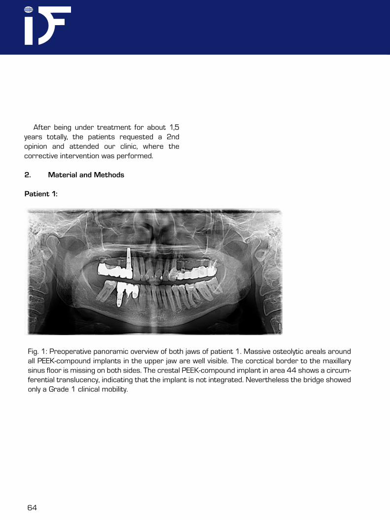
In this report we describe the necessary corrective intervention in two patients which had received treatment with a specific type of plastic implants. A 45 year old female (patient 1) healthy patient, non-smoker, and a 46 year old healthy male patient (patient 2), non-smoker, requested advice after recurrent complications with the implants in the upper jaw had taken place. The panoramic overview radiograph of both patients revealed massive osteolytic areas around four lateral basal implants in the upper jaw, Figs. 1 and 2. The implants had been equipped with prosthetics in an immediate load protocol within a few days postoperatively. Later several surgical corrections had been under-taken, but the problems (chronic infection, pain, mobility) persisted.
1 Perso-C and Perso-B implants. Supplier: F.-P. Spahn Genkersteenweg 470, BE-3500 Hasselt, Belgium. Perso-C, Perso-B, and Sisomm are registered trade-marks of Victory-med n.v., Heidestraat 99, 3581 Beverlo, Belgium
64
After being under treatment for about 1,5 years totally, the patients requested a 2nd opinion and attended our clinic, where the corrective intervention was performed.
2. Material and Methods
Patient 1:
Fig. 1: Preoperative panoramic overview of both jaws of patient 1. Massive osteolytic areals around all PEEK-compound implants in the upper jaw are well visible. The corctical border to the maxillary sinus floor is missing on both sides. The crestal PEEK-compound implant in area 44 shows a circum-ferential translucency, indicating that the implant is not integrated. Nevertheless the bridge showed only a Grade 1 clinical mobility.
CMF. Impl. Dir. Vol. 8 No. 3-2 2013 65
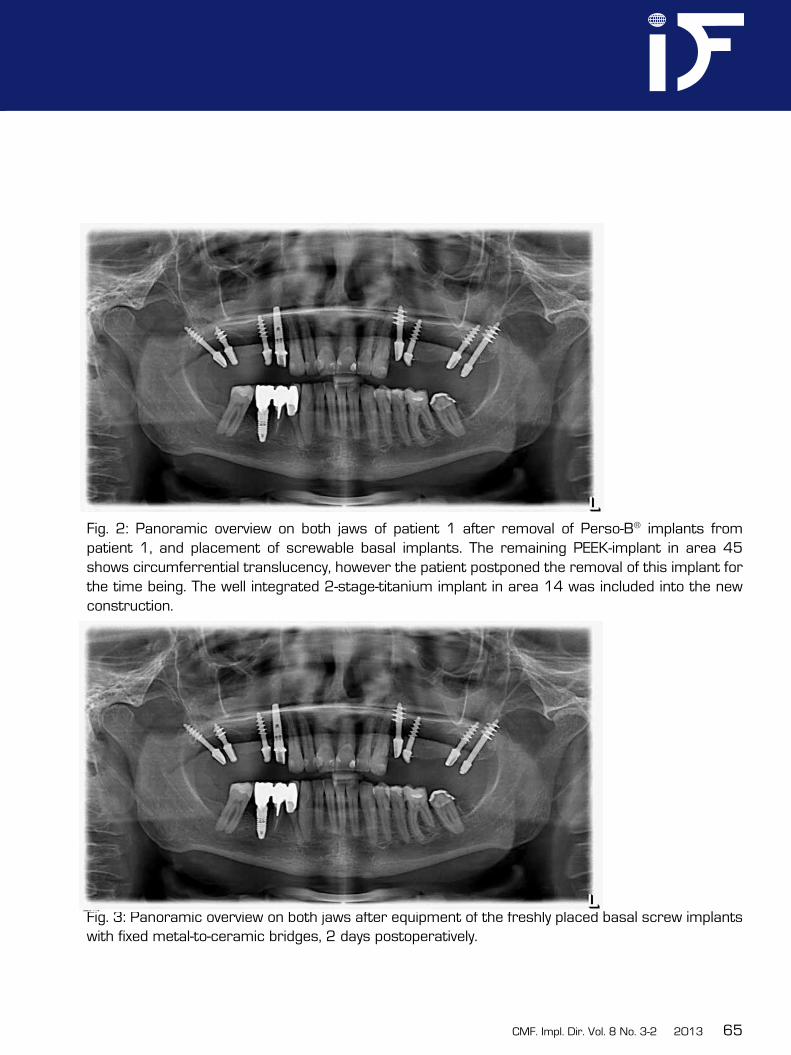
Fig. 2: Panoramic overview on both jaws of patient 1 after removal of Perso-B® implants from patient 1, and placement of screwable basal implants. The remaining PEEK-implant in area 45 shows circumferrential translucency, however the patient postponed the removal of this implant for the time being. The well integrated 2-stage-titanium implant in area 14 was included into the new construction.
Fig. 3: Panoramic overview on both jaws after equipment of the freshly placed basal screw implants with fixed metal-to-ceramic bridges, 2 days postoperatively.
66
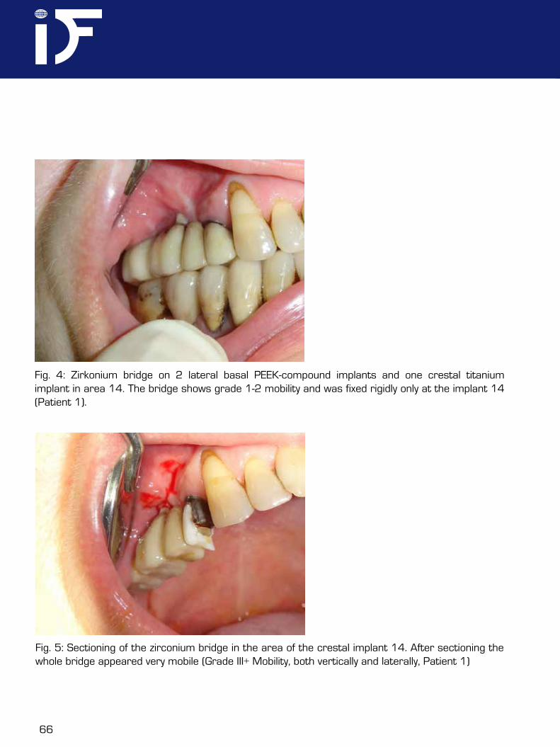
Fig. 4: Zirkonium bridge on 2 lateral basal PEEK-compound implants and one crestal titanium implant in area 14. The bridge shows grade 1-2 mobility and was fixed rigidly only at the implant 14 (Patient 1).
Fig. 5: Sectioning of the zirconium bridge in the area of the crestal implant 14. After sectioning the whole bridge appeared very mobile (Grade III+ Mobility, both vertically and laterally, Patient 1)
CMF. Impl. Dir. Vol. 8 No. 3-2 2013 67
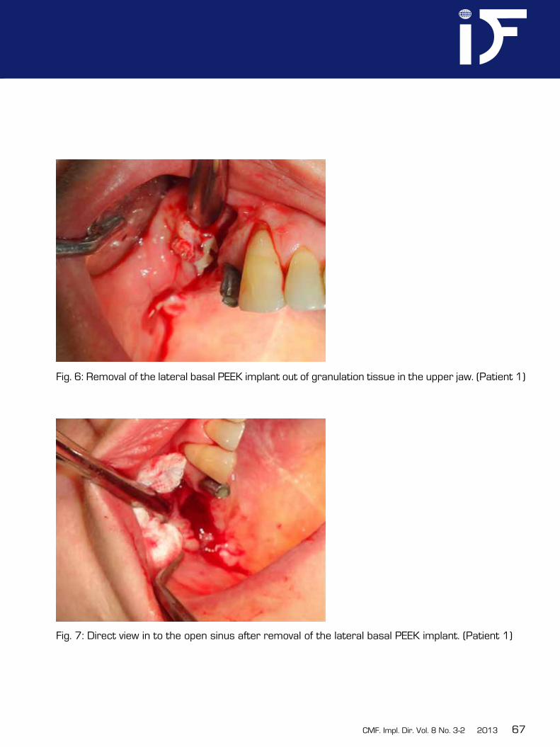
Fig. 6: Removal of the lateral basal PEEK implant out of granulation tissue in the upper jaw. (Patient 1)
Fig. 7: Direct view in to the open sinus after removal of the lateral basal PEEK implant. (Patient 1)
68
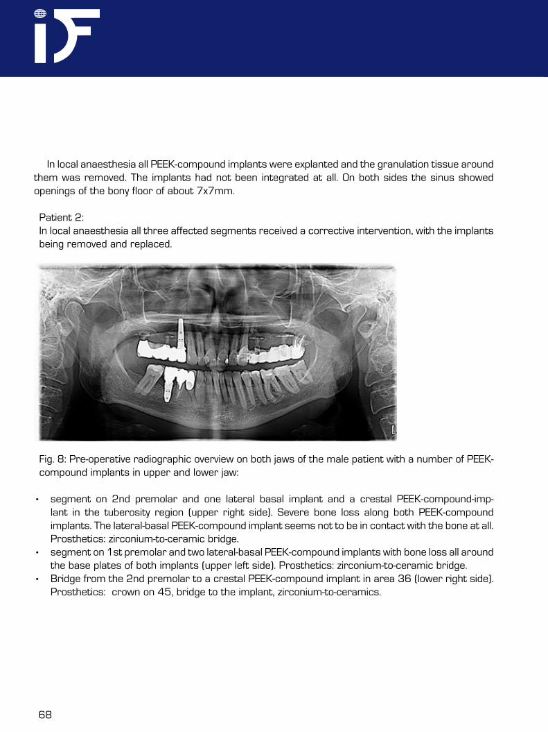
Fig. 8: Pre-operative radiographic overview on both jaws of the male patient with a number of PEEK-compound implants in upper and lower jaw:
• segment on 2nd premolar and one lateral basal implant and a crestal PEEK-compound-imp-lant in the tuberosity region (upper right side). Severe bone loss along both PEEK-compound implants. The lateral-basal PEEK-compound implant seems not to be in contact with the bone at all. Prosthetics: zirconium-to-ceramic bridge.
• segment on 1st premolar and two lateral-basal PEEK-compound implants with bone loss all around the base plates of both implants (upper left side). Prosthetics: zirconium-to-ceramic bridge.
• Bridge from the 2nd premolar to a crestal PEEK-compound implant in area 36 (lower right side). Prosthetics: ¾crown on 45, bridge to the implant, zirconium-to-ceramics.
In local anaesthesia all PEEK-compound implants were explanted and the granulation tissue around them was removed. The implants had not been integrated at all. On both sides the sinus showed openings of the bony floor of about 7x7mm.
Patient 2: In local anaesthesia all three affected segments received a corrective intervention, with the implants being removed and replaced.
CMF. Impl. Dir. Vol. 8 No. 3-2 2013 69
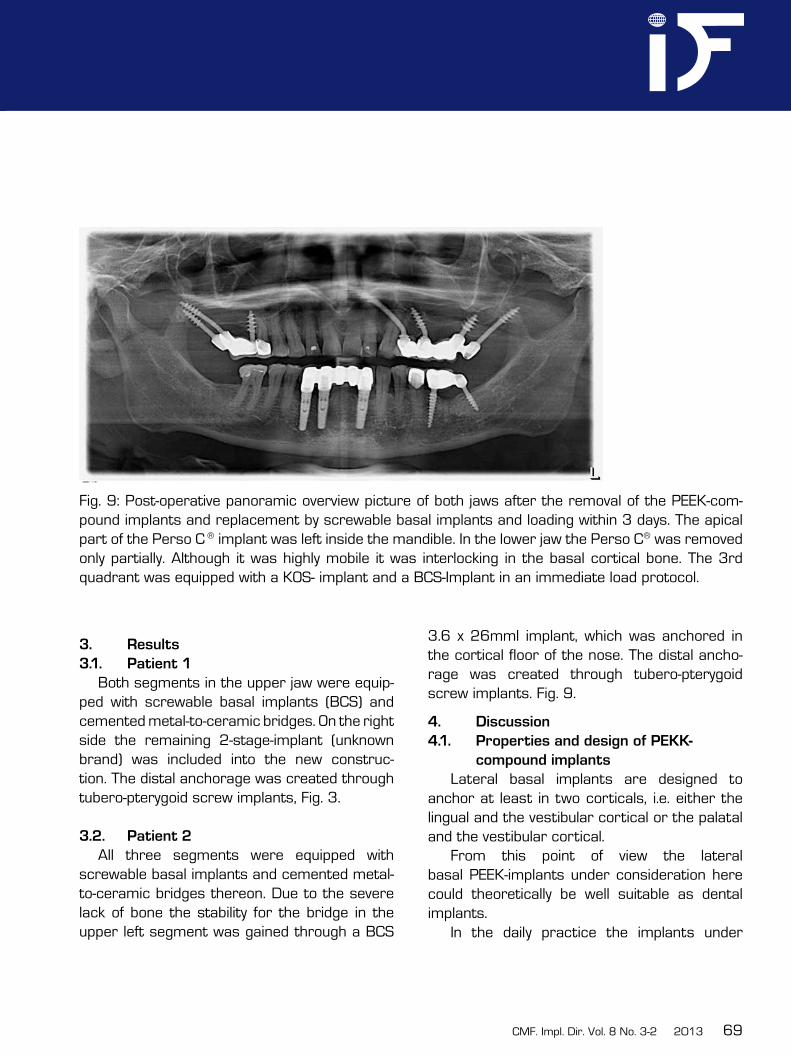
Fig. 9: Post-operative panoramic overview picture of both jaws after the removal of the PEEK-com-pound implants and replacement by screwable basal implants and loading within 3 days. The apical part of the Perso C ® implant was left inside the mandible. In the lower jaw the Perso C® was removed only partially. Although it was highly mobile it was interlocking in the basal cortical bone. The 3rd quadrant was equipped with a KOS- implant and a BCS-Implant in an immediate load protocol.
3. Results
3.1. Patient 1
Both segments in the upper jaw were equip-ped with screwable basal implants (BCS) and cemented metal-to-ceramic bridges. On the right side the remaining 2-stage-implant (unknown brand) was included into the new construc-tion. The distal anchorage was created through tubero-pterygoid screw implants, Fig. 3.
3.2. Patient 2
All three segments were equipped with screwable basal implants and cemented metal-to-ceramic bridges thereon. Due to the severe lack of bone the stability for the bridge in the upper left segment was gained through a BCS
3.6 x 26mml implant, which was anchored in the cortical floor of the nose. The distal ancho-rage was created through tubero-pterygoid screw implants. Fig. 9.
4. Discussion
4.1. Properties and design of PEKK-
compound implants
Lateral basal implants are designed to anchor at least in two corticals, i.e. either the lingual and the vestibular cortical or the palatal and the vestibular cortical.
From this point of view the lateral basal PEEK-implants under consideration here could theoretically be well suitable as dental implants.
In the daily practice the implants under
70
consideration here are however unsuitable and there are a number of good reasons for this statement:• lateral basal implants might work well if
the base plate is hidden deep in the bone, and far away from the mucosal penetrati-on to the contaminated oral cavity. In such indications any screw implant would work also. The main indications of lateral basal implants are regions with reduced vertical bone supply. If applied in exactly these ca-ses PEEK lateral basal implants may cause severe problems such as massive osteolysis.
• The manufacturer has designed the implant to be adjusted in size during the operati-on. At first glance this seems a very clever solution, because the implantologists manages with one size of implants only and he can trim the implant down to the desired diameter. In the clinical reality this solution is connected to a number of unacceptable disadvantages:a.) If the implant is trimmed during the operation the surface remains contami-nated with small chipped of particle which can not be removed safely. These particles may lead to granulation and propagate in-fections. A validated intra-operative cleaning procedure for implants does not exist.b.) As a result of the trimming the load transmission areas are reduced in an uncontrolled way. Earlier investigations have shown, that the amount of load transmissi-on surface of the lateral basal implant on each side of the vertical implant part, i.e. the distribution of masticatory forces on each
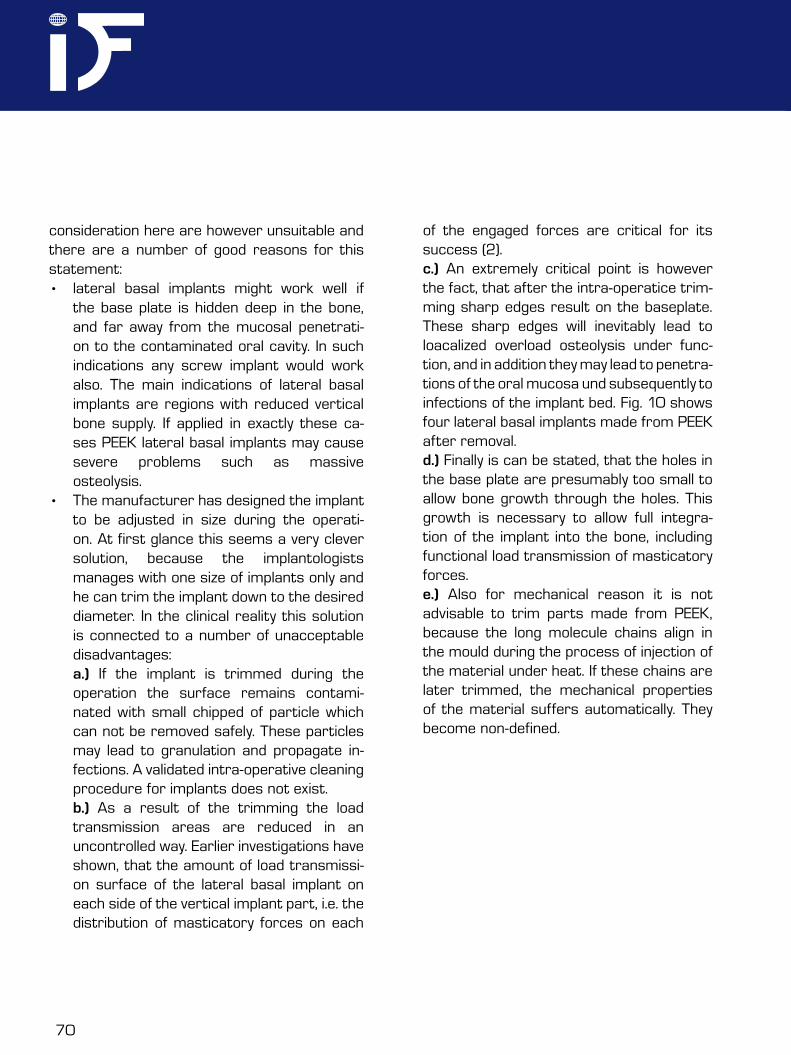
of the engaged forces are critical for its success (2).c.) An extremely critical point is however the fact, that after the intra-operatice trim-ming sharp edges result on the baseplate. These sharp edges will inevitably lead to loacalized overload osteolysis under func-tion, and in addition they may lead to penetra-tions of the oral mucosa und subsequently to infections of the implant bed. Fig. 10 shows four lateral basal implants made from PEEK after removal.d.) Finally is can be stated, that the holes in the base plate are presumably too small to allow bone growth through the holes. This growth is necessary to allow full integra-tion of the implant into the bone, including functional load transmission of masticatory forces.e.) Also for mechanical reason it is not advisable to trim parts made from PEEK, because the long molecule chains align in the mould during the process of injection of the material under heat. If these chains are later trimmed, the mechanical properties of the material suffers automatically. They become non-defined.
CMF. Impl. Dir. Vol. 8 No. 3-2 2013 71
It is known that implants made from PEEK show a significantly lower bone-to-implant contact (BIC) compared to implants made from titanium or titanium alloy (1). This leads to the necessity to safely engage the base plate into corticals, as these parts of the bone show a high-er tendency to heal and thereby integrate the implants. Note that all dental implants should at least allow the active biologic integration of the endosseous (central) parts of the implants into the bone. The implants under discussion here do not allow this integration especially in case with reduced bone height.
• an implant which is by design determined to be applied in sites with reduced bone heights (i.e. lateral basal dental implants), must be suitable for application in reduced bone heights under all aspects. If this is not the case, it must be considered a potential danger.
The manufacturer of the dental implants under discussion here claims, that PEEK(-compound) as an implant material is extremely advantageous, because the material is “iso- elastic”, i.e. the Modulus of Elasticity of the material is near to that of “the bone”. At the first glance this argument seems to be of high
Fig. 10: Four lateral basal implants made from modified PEEK after removal out of massive granula-tions in patient 1, upper jaw. Note that the implants were inserted exactly in the shape as shown here. It was not necessary to cut anything off from the implants during the removal, as they were not osseo-integrated at all. Hence the surgeon had trimmed these implants in this way.
72
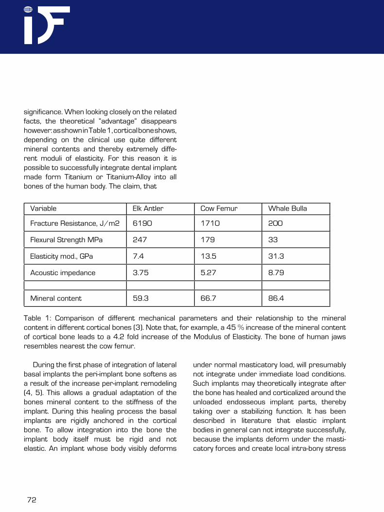
significance. When looking closely on the related facts, the theoretical “advantage“ disappears however: as shown in Table 1, cortical bone shows, depending on the clinical use quite different mineral contents and thereby extremely diffe-rent moduli of elasticity. For this reason it is possible to successfully integrate dental implant made form Titanium or Titanium-Alloy into all bones of the human body. The claim, that
Variable Elk Antler Cow Femur Whale Bulla
Fracture Resistance, J/m2 6190 1710 200
Flexural Strength MPa 247 179 33
Elasticity mod., GPa 7.4 13.5 31.3
Acoustic impedance 3.75 5.27 8.79
Mineral content 59.3 66.7 86.4
Table 1: Comparison of different mechanical parameters and their relationship to the mineral content in different cortical bones (3). Note that, for example, a 45 % increase of the mineral content of cortical bone leads to a 4.2 fold increase of the Modulus of Elasticity. The bone of human jaws resembles nearest the cow femur.
During the first phase of integration of lateral basal implants the peri-implant bone softens as a result of the increase per-implant remodeling (4, 5). This allows a gradual adaptation of the bones mineral content to the stiffness of the implant. During this healing process the basal implants are rigidly anchored in the cortical bone. To allow integration into the bone the implant body itself must be rigid and not elastic. An implant whose body visibly deforms
under normal masticatory load, will presumably not integrate under immediate load conditions. Such implants may theoretically integrate after the bone has healed and corticalized around the unloaded endosseous implant parts, thereby taking over a stabilizing function. It has been described in literature that elastic implant bodies in general can not integrate successfully, because the implants deform under the masti-catory forces and create local intra-bony stress
CMF. Impl. Dir. Vol. 8 No. 3-2 2013 73
peaks and subsequent osteolysis (6). Elastic implant designs do not provide a defined amount of load transmitting interface, becau-se only a part of the surface participates in the load transmission while other parts of the implant are shielded from forces while deforma-tion takes place.
When searching the literature about PEEK dental implants, only a few citations are found. The treatment descriptions of Karan et all. (7) reveals besides a very good background descrip-tion also two excellent radiographs, which show
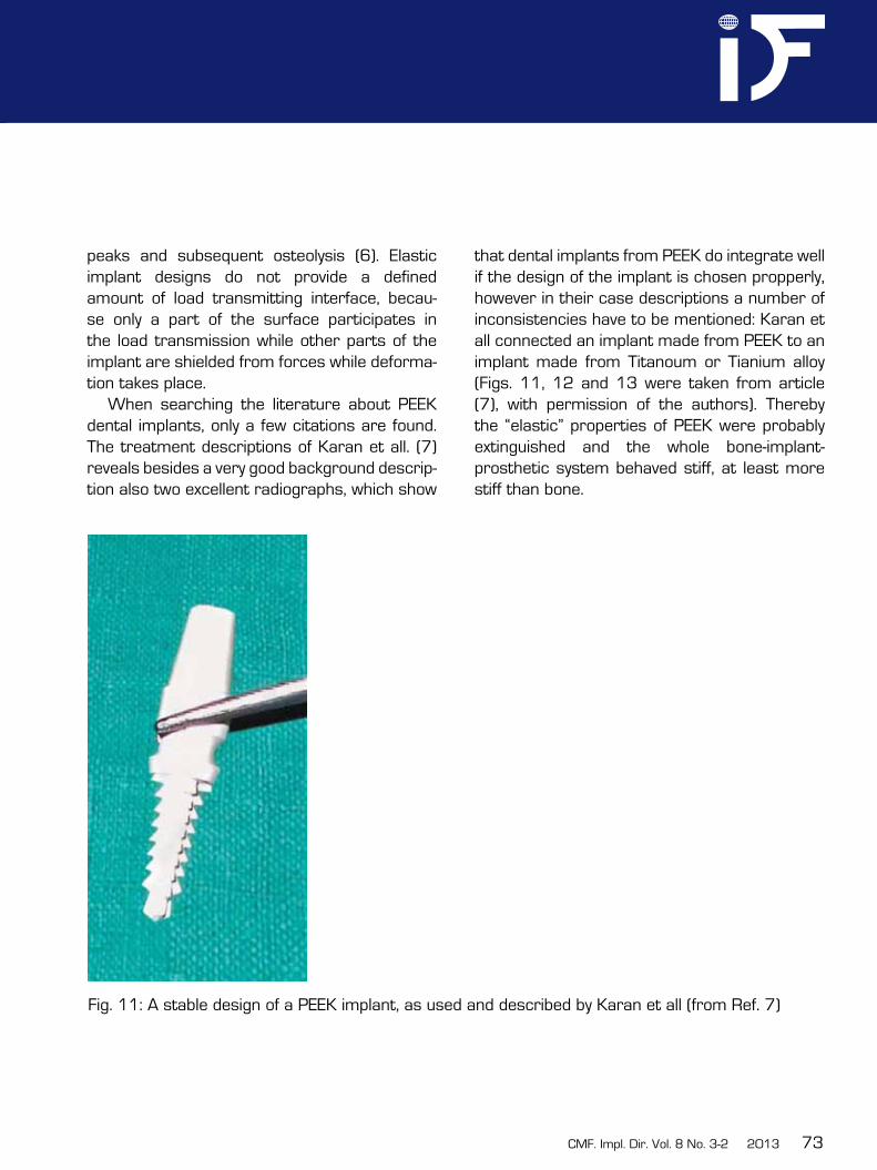
that dental implants from PEEK do integrate well if the design of the implant is chosen propperly, however in their case descriptions a number of inconsistencies have to be mentioned: Karan et all connected an implant made from PEEK to an implant made from Titanoum or Tianium alloy (Figs. 11, 12 and 13 were taken from article (7), with permission of the authors). Thereby the “elastic” properties of PEEK were probably extinguished and the whole bone-implant- prosthetic system behaved stiff, at least more stiff than bone.
Fig. 11: A stable design of a PEEK implant, as used and described by Karan et all (from Ref. 7)
74
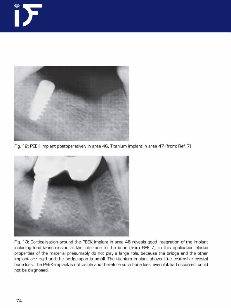
Fig. 12: PEEK implant postoperatively in area 46, Titanium implant in area 47 (from: Ref. 7)
Fig. 13: Corticalisation around the PEEK implant in area 46 reveals good integration of the implant including load transmission at the interface to the bone (from REF 7). In this application elastic properties of the material presumably do not play a large role, because the bridge and the other implant are rigid and the bridge-span is small. The titanium implant shows little crater-like crestal bone loss. The PEEK-implant is not visible and therefore such bone loss, even if it had occurred, could not be diagnosed.
CMF. Impl. Dir. Vol. 8 No. 3-2 2013 75
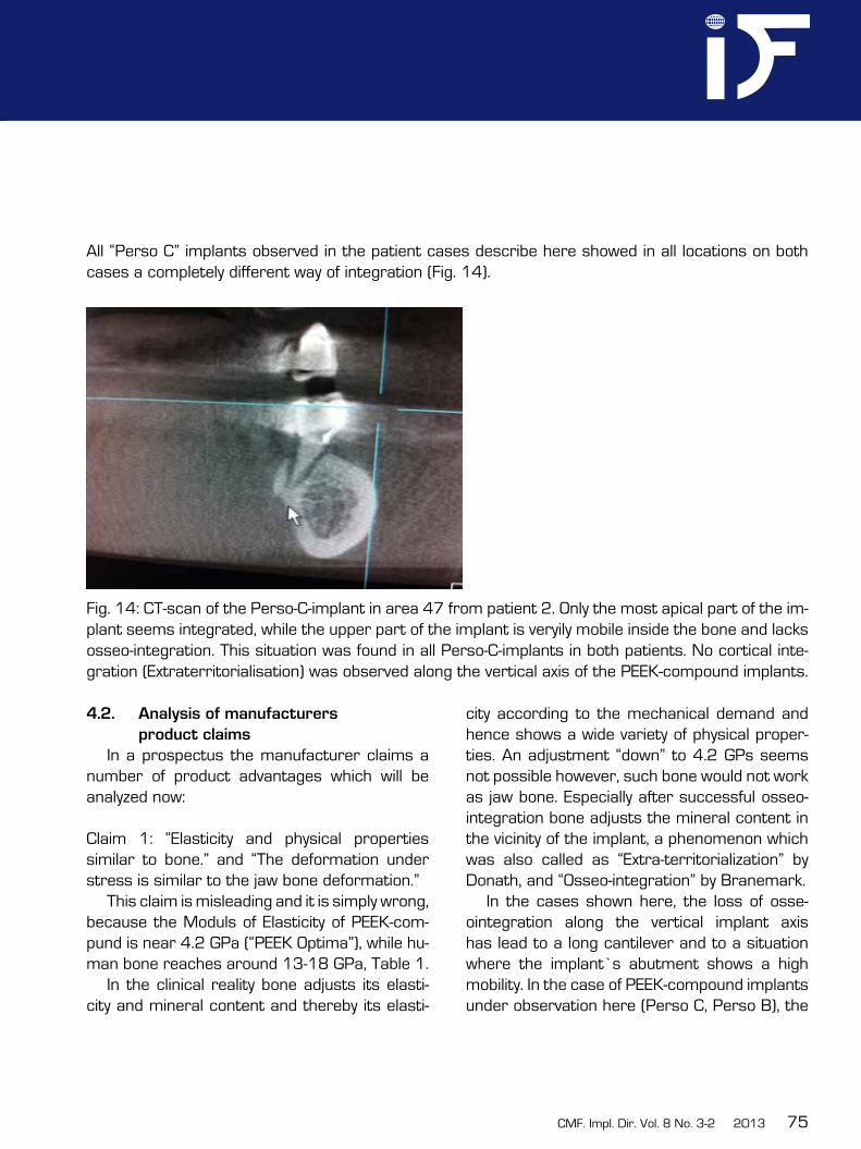
All “Perso C” implants observed in the patient cases describe here showed in all locations on both cases a completely different way of integration (Fig. 14).
Fig. 14: CT-scan of the Perso-C-implant in area 47 from patient 2. Only the most apical part of the im-plant seems integrated, while the upper part of the implant is veryily mobile inside the bone and lacks osseo-integration. This situation was found in all Perso-C-implants in both patients. No cortical inte-gration (Extraterritorialisation) was observed along the vertical axis of the PEEK-compound implants.
4.2. Analysis of manufacturers
product claims
In a prospectus the manufacturer claims a number of product advantages which will be analyzed now:
Claim 1: “Elasticity and physical properties similar to bone.” and “The deformation under stress is similar to the jaw bone deformation.”
This claim is misleading and it is simply wrong, because the Moduls of Elasticity of PEEK-com-pund is near 4.2 GPa (“PEEK Optima”), while hu-man bone reaches around 13-18 GPa, Table 1.
In the clinical reality bone adjusts its elasti-city and mineral content and thereby its elasti-
city according to the mechanical demand and hence shows a wide variety of physical proper-ties. An adjustment “down” to 4.2 GPs seems not possible however, such bone would not work as jaw bone. Especially after successful osseo-integration bone adjusts the mineral content in the vicinity of the implant, a phenomenon which was also called as “Extra-territorialization” by Donath, and “Osseo-integration” by Branemark.
In the cases shown here, the loss of osse-ointegration along the vertical implant axis has lead to a long cantilever and to a situation where the implant’s abutment shows a high mobility. In the case of PEEK-compound implants under observation here (Perso C, Perso B), the
76
low Modulus of Elasticity is combined with an unsuitable design of the implants, and this must lead to frequent problems in the clinical reality. Implant materials with higher Modulus of Elasti-city , e.g. “Motis” (a PEEK compound with carbon fiber enforcement) could work better, because it reaches values of up to 12 GPa, which is in fact close to the bone. Unfortunately this material is black, and the water uptake of all compounds of PEEK is considerably high.
PEEK has stable crystalline form but when blended with composites like carbon fibres by injection moulded technique, there are changes of nucleation in polymers and a change in original crystallinity. Furthermore it becomes impossible to predict the mechanical behaviour of the device and the load transmission proper-ties, if randomly parts of the implants are cut off and the long chains of molecules are altered and shortened.
Note that the “osteolytic” situation seen in both patients in the upper jaw around the PEEK-compound implants could also be inter-preted as a reduction of mineralization of the bone, and this could be the bones answer to the (from bone’s point of view) hyper-elastic implant material. This process could add up with localized overload due to the very sharp implants edges, and result in the massive loss of bone which we have observed.
Claim 2: “No artefacts in radiographic imaging”.
This claim is also misleading, as modern CT-machines provide good pictures without artefacts even around multiple implant cases. The downside of PEEK also PEEK-compounds
with BaSO4 is the low radiographic visibility and the low optical visibility of the material in the bleeding environment of the operation site. This makes it extremely difficult to remove especially partially integrated and highly mobile implants which hold in macro-retention.
Claim 3: “No heating in MR-imaging and X-ray-therapy.” And “there is no need to remove the implant for type”.
Also this claim is misleading, as heating around dental implants in MR-imaging was never described, and there is no such thing like “X-ray-Therapy”. In case that the author of the prospectus wanted to express that modified PEEK/implants are safe to use in case of a combined chemotherapy with ray-therapy, he is presumably also wrong, because at least in the two cases observed here, massive infec-tion and osteolysis was seen even without such therapy. Who would remove a metallic dental implant for a CT-scan?
Claim 4: “Metal free, no corrosion” The authors do not see any advantage in
metal free implants or constructions and the claim that there is “no corrosion” is therefore also misleading. In the oral cavity corrosion or currents between different metals play a minor role, because the saliva constantly tends to extinguish electrical potentials. For the durability of treatments and especially cementations and for protection against (secondary) caries, the real problem is gap-corrosion which can occur between all kinds of materials. e.g. between (all type of) abutment heads, also at natural abutments, and the prosthetic constructions.
CMF. Impl. Dir. Vol. 8 No. 3-2 2013 77
This gap corrosion affects also non-metallic molecules and it can only be overcome by precise prosthetic work-pieces and precise cementations.
The claim of a “metal free”-therapy is anyway absurd, if bridges from zirconium are then incorporated on PEEK implants. Zirkonium is a metal.
Titanium and titanium are constantly covered by a stable layer of oxygenized titanium and this layer prevents any other corrosion as it can be seen e.g. on corrosive metals such as iron.
Claim 5: “Post extraction insertion in all sectors”. We consider also this claim mislea-ding, because from our observations we had to come to the conclusion, that immediate loading around the implants under discussion here is not a good option, especially in low bone cases.
Claim 6: “Due to the equivalent flexibility of jaw bone the implants PEEK Perso C®, and Perso B® will stimulate the remodeling of bone (Osteoconduction).”
This claim lacks not only of any proof, it is simply wrong:• PEEK does not stimulate the remodeling of
bone, • such a remodeling is the last thing we would
want in dental implantology. Implants need highly corticalized bone around them and mechanical stability as well as the lowest possible metabolic activity, and possibly wit-hout and osteonal remodelling.
• Osteoconduction is not found in PEEK at all. It is known, that PEEK shows a low bone-to-implant contact (BIC) and it integrates main-
ly in the corticals due to the high tendencyof all corticals to close (repair) after injuries.
Claim 7: “Adjusting the implant to the patient and not vice versa”.This claim seems to aim at the “isoelastic properties” of the implant material. As pointed out under claim 1, iso-elasticity is neither an advantage nor a prerequisite for osseo-integra-tion. In fact over the last 30 years is has been proven that implants of all kinds, made from Titanium and Titanium alloy, integrate nicely and predicably.
4.3. Radiographic evaluation
Implants from pure PEEK are not visible in x-ray at all (Figs. 12, 13). Implants from modified PEEK-compound, containing BaSO4 as x-ray-marker are visible so some minor extend in radiographs. At least this allows to evaluate their integration and to localize the implants.
As implant failures are mostly multi-cau-sal we must consider other reasons for the failure also. Possible reasons are wrong prosthetic equipment of the implants (i.e. either wrong prosthetic strategy or mistakes in the design of the prosthetics). Furthermore failure of cementation may be contributing. In the two cases some of the implants did not show any connection to the bridgework, and nevertheless the lateral-basal implants did not integrate at all. This may indicate, that lateral-basal implants made from PEEK-compound show a low inte-gration potential at least in the resorbed distal maxilla.
78
4.4. Comments on the design of axial
Perso-C®- implants.
Perso C implants may work well under optimum conditions, when no vertical bone loss takes place along the axis of the implant. As soon as the bone recesses however, the remai-ning parts of the implant (i.e. the parts ancho-red deep in the bone) are too thin to withstand the masticatory forces and the implant body deforms. Namely lateral forces will then bend the implant to both sides, lingual and lateral, which leads to even more bone loss, until finally only the apex of the implant remains integra-ted in the 2nd cortical. The design of Perso® C implants do not take into consideration the possibility of vertical bone loss, they are designed for the ideal case only. In fact the more bone is lost, the more deformable the implant gets, Hence higher localized stresses in the descending neck area will occur and more bone will be lost. As soon as vertical bone gets lost, these implants are not iso-elastic any more, they are wobbly.
4.5. Alternative treatment possibilities
and outcome evaluation
As an alternative to our treatment it would also have been possible to first extract the implants and then (in a second intervention) to carry out a conventional sinuslift or bone block augmentation, followed by 2-stage- implant placement. The patients did not desire these lengthy treatment protocols. Due to the large perforations of the basal sinus corticals a conventional sinuslift would have been more risky than in “normal” cases, where the lower cortical of the sinus is still present and a
minimal residual height of the alveolar crest supports new bone formation and the maturati-on of the graft. Therefore probably a bone block transplant would have been the method of first choice to reconstruct the inferior sinus wall.
We would like to point out that right now we can not report about the long term outcome of our treatment.
4.6. Bridge material considerations
From mechanical point of view it makes no sense to combine elastic (deformable) implant designs with a super-stiff bridge mate-rial as done here: Zirkonium shows virtually no elasticity at all. In combination with non-resistant (i.e. “iso-elastic to bone”) implant material and deformable implant designs this leads to a situation where localized loads will be hitting only one implant (the one nearest to the load) and they will deform it, thereby overloading the bone. Sarot et all (8) reported as a result of their FEM-calculation similar: in CRF-PEEK implants, compared to titanium implants, the stresses are 30 % higher in the neck area and the adjacent bone.
This event is especially likely in immediate load procedures when the bone near the load transmission surfaces is under strong posto-perative remodeling while being loaded from mastication.
Deformable implants never give the desired result of better load distribution or adapta-tion (9). Higher loads always require larger load transmission surfaces or bone of larger resistance, i.e. higher local mineralization or cortical/corticalized bone.

CMF. Impl. Dir. Vol. 8 No. 3-2 2013 79
4.7. Consideration on the possibility of
cementation
If, as pointed out under 4.6, single implants deform, other abutment of the bridges may not deform. This leads to a situation where single abutments come under tensile forces, and on these abutments the cementation will then fail. PEEK and PEEK-compound abutments show no roughness, because they are created in an injection moulding process. Roughening them up in the oral cavity is dangerous and gives an unpredictable mechanical result, because mechanical destruction of the molecules, which were well aligned during the production of the implants, leads to follow-up destruction of the molecules integrity and adhesion. Hence cementations on the destroyed surfaces will be likely to fail, and exactly this was observed in the two patient cases.
5. Conclusion
In this article two cases are discussed, which had been treated with crestal and lateral-basal PEEK-compound-implants. Both patients recei-ve their implants in the same clinic in Western-Europe. This is not a case series, nor a cohort study, we are reporting on two similar clinical cases treated under the same conditions and with identical medical devices.
As our analysis shows, probably many of the claims of the manufacturer are not true, and in the clinical reality we found many flaws in the devices.
Our analysis also shows, that probably several of the features of these implants (such as: thin and overly elastic design of both vertical and lateral-basal designs, large muco-sal penetration diameter, low contact area of
the crestal types to bone, small holes in the base-plates with subsequent blockage of blood supply and bony pervasion, missing possibility to adjust the implants bone transmitting surface with at least some precision) will lead to typical fai-lure patterns, especially in low bone cases and in immediate loading.
Low visibility on X-ray and in during the operation makes it difficult to remove partially integrated (actually: mechanically locked-in parts of) crestal types of the implants under investigation here. Besides the extremely low costs of production (less than 1 Eur per piece), the design of Perso C® and Perso B® do not provide any advantages and there are a number of massive risks for the patients associated to these implants.
We would like to point out that PEEK and PEEK-Compounds (e.g. those showing high-er Modulus of Elasticity) as such may be well suitable for use in traumatology and even dental implantology, if propper implant designs and adequate treatment protocols are chosen.
The question, whether or not is makes sense to search for a replacement of well suitable and force resistant titanium and titani-um alloy in dental implantology, must be raised at this point. Allergies to titanium as implant materials are extremely rare and mainly used as an excuse to unknowledgable patients after failing dental implant treatments.
80
Literature
1. Schwittala A.D., Müller W.D., PEEK Dental Implants: A review of the literature J Oral Implantol. 2011 Sep 9,
2. Himmlova. L., Goldman T, Ihde S. Mechanics meet Biomechanis, Chapter 14, pp. 264 – 276. in “Immediate Loading”, Ihde S., Ihde A. Edts., Intl. Implant Foundation Publishing, Munich/ Germany 2012, ISBN 987-3-9851468-3-5
3. Currey JD In: Covin SC (ed) Mechanical properties of none; Am Soc. Of Mech. Engineers, New York, 1981; pp. 13-26.
4. Kopp S., Kuzelka J., Goldman T, Himmlova L. Ihde S. Modelling of load transmission and distribution of deformation energy befroe and after healing of basal dental implants in the human mandible. Biomed Tech (Berl). 2011;56(1):53-8. (Epub 2010 Nov 17)
5. Ihde S., T. Goldmann, L. Himmlova, Z. Aleksic, J. Kuzelka Implementation of Contact Definitions Calculated by FEA to Describe the Healing Process of Basal implants. Biomed Pap Med Fac Univ Palacky Olomouc Czech Repub. 2008, 152 (1): 1 – 6
6. Breme J, Biehl V, Schulte W et al: Development and functionality of isoelastic dental implants of titanium alloys. Biomaterials, 1993; 14:887–892. 7. Karan Marya et al: Polyetheretherketone (PEEK) Dental Implants: a case for Immediate loading. Int. J . Oral Impl. Clin. Res. 2(2): 97-103, 2011
8. Sarot J.R., Contar C.M., Cruz A.C., de Souza Magini R. Evaluation of the stress distribution in CFR-PEEK dental implants by the 3-dimensional finite element method. J. Mater Sci: Mater Med; 2010, 21: 2079-85
9. Richter E.J.: Ein Beitrag zur Erläuterung des Begriffs “Stossdämpfung” in der Implantologie. Z Zahnärztl Implantol; 1986, 2:270–273.

CMF. Impl. Dir. Vol. 8 No. 3-2 2013 81
82
2
id im
pla
nt
diR
ecti
on
s e
du
ca
tio
na
l v
ideo
seR
ies
published by if publishing, geRmany oRdeR no.: 6669
Maxillary iMplant placeMent >>
Replacing Replace®
Cranio-maxilofacial
Implant Directions®
Educational Video Series
educational Video SerieS
Maxillary Implant Placement
1 cRestal & basal implants Order Nr. 6667
2 and Replacing Replace® Order Nr. 6669
Each DVD contains approx. 20 minutes of oral surgery. With explanations in english and ger-man language.
€ 35,00
Please send your order via e-mail to:[email protected]
or via regular postage mail to:International Implant Foundation Leopoldstr. 116, DE-80802 München
Guide for Authors
ID publishes articles, which contain information, that will impro-ve the quality of life, the treatment outcome, and the affordability of treatments.The following types of papers are published in the journal: Full length articles (maximum length abstract 250 words, to-tal 2000 words, references 25, no limit on tables and figures). Short communications including all case reports (maximum length abstract 150 words, total 600 words, references 10, fi-gures or tables 3) Technical notes (no abstract, no introduction or discussion, 500 words, references 5, figures or tables 3). Interesting cases/lessons learned (2 figures or tables, legend 100 words, maximum 2 references).
Literature Research and Review articles are usually commis-sioned.Critical appraisals on existing literature are welcome.
Direct submissions to:[email protected] text body (headline, abstract, keywords, article, conclusion), tables and figures should be submitted as separate documents. Each submission has to be accompanied by a cover letter. The cover letter must mention the names, addresses, e-mails of all authors and explain, why and how the content of the article will contribute to the improvement of the quality of life of patients.
id im
pla
nt
diR
ecti
on
s e
du
ca
tio
na
l v
ideo
seR
ies
published by if publishing, geRmany oRdeR no.: 6667
Maxillary iMplant placeMent >>
cRestal & basal implants
Cranio-maxilofacial
Implant Directions®
Educational Video Series
1