IMPL BIOTELEMETRY SYSTEMS - NASA · 2013-08-31 · NASA SP-5094 TECH LIBWRY KAFB, NM IMPLANTABLE...
121
M7/-27983 NASA SP-5094 IMPL BIOTELEMETRY SYSTEMS A REPORT https://ntrs.nasa.gov/search.jsp?R=19710018507 2020-04-14T20:12:27+00:00Z
Transcript of IMPL BIOTELEMETRY SYSTEMS - NASA · 2013-08-31 · NASA SP-5094 TECH LIBWRY KAFB, NM IMPLANTABLE...

M7/-27983
NASA SP-5094
IMPL BIOTELEMETRY SYSTEMS
A REPORT
https://ntrs.nasa.gov/search.jsp?R=19710018507 2020-04-14T20:12:27+00:00Z
NASA SP-5094 TECH LIBWRY KAFB, NM
IMPLANTABLE BIOTELEMETRY SYSTEMS
A REPORT
BY Thomas B. Fryer
Ames Research Center
Technology Utilization Divtsion OFFICE OF TECHNOLOGY UTILIZATION 1970 NATIONAL AERONAUTICS AND SPACE ADMINISTRATION
Washington, D.C.
NOTICE This document was prepared under the sponsorship of the National Aero- nautics and Space Administration. Neither the United States Government nor any person acting on behalf of the United States Government assumes any liability resulting from the use of the information contained in this document, or warrants that such use will be free from privately owned rights.
For sale by the Superintendent of Documents,
U.S. Government Printing Office, Washington, D.C. 20402
Price 55 cents
Library of Congress Catalog Card Number 75-606340

Foreword
With the advent of manned space flight, the National Aeronautics and Space Administration (NASA) has conducted intensive investigations on the physiological makeup of the human body. The last decade has seen major advances in the use of radiotelemetry in physiological research. Revolutionary developments in microelectronics are making possible smaller telemetry sys- tems that can be wholly implanted in laboratory animals. The NASA Ames Research Center has been in the fore-front of such research and has developed many implantable biotelemetry devices now considered by many as a standard method for monitoring physiological functions in animals. This report de- scribes biotelemetry developments at Ames, tracing the evolution of concepts underlying the accurate and reliable biotelemetry systems of today. Such sys- tems are described in sufficient detail for the reader to select designs to meet specific needs.
Through its Technology Utilization Program, NASA strives to make the results of such work widely available for the use of those outside the aerospace community. This publication is one of a series intended to achieve those ob- jectives.
RONALD J. PHILIPS, DIRECTOR TECHNOLOGY UTILIZATION OFFICE


Contents
Page Chapter 1 . INTRODUCTION . . . . . . . . . . . . . . . . . . . . . . . . . . . . . . . . . . . . 1
Early Developments . . . . . . . . . . . . . . . . . . . . . . . . . . . . . . . . . . . . . . . . 1 Requirements fo r Implantation . . . . . . . . . . . . . . . . . . . . . . . . . . . . . . . . 2 Basic Concepts in Design . . . . . . . . . . . . . . . . . . . . . . . . . . . . . . . . . . . . . 2
. . . . . . . . . . . . . . . . . . . . . . . . . . Chapter 2 . BIOPOTENTIAL TELEMETRY 5 Transmitter . . . . . . . . . . . . . . . . . . . . . . . . . . . . . . . . . . . . . . . . . . . . . 5 Receiver . . . . . . . . . . . . . . . . . . . . . . . . . . . . . . . . . . . . . . . . . . . . . . . . 7 Demodulator . . . . . . . . . . . . . . . . . . . . . . . . . . . . . . . . . . . . . . . . . . . . 7 Alternative Circuit . . . . . . . . . . . . . . . . . . . . . . . . . . . . . . . . . . . . . . . . . 8
. . . . . . . . . . . . . . . . . . . . . . . . . . . . . . . . . . . . . . . . Subcarrier Oscillator 9 Performance . . . . . . . . . . . . . . . . . . . . . . . . . . . . . . . . . . . . . . . . . . . . . 10
. . . . . . . . . . . . . . . . . . . . . . . . . . . Chapter 3 TEMPERATURE TELEMETRY 13 System Design . . . . . . . . . . . . . . . . . . . . . . . . . . . . . . . . . . . . . . . . . . . . 13 Radio-Frequency Operation . . . . . . . . . . . . . . . . . . . . . . . . . . . . . . . . . . . 16 Demodulator . . . . . . . . . . . . . . . . . . . . . . . . . . . . . . . . . . . . . . . . . . . . 16 Tests . . . . . . . . . . . . . . . . . . . . . . . . . . . . . . . . . . . . . . . . . . . . . . . . . . 17
Chapter 4 . MODIFIED SINGLE-CHANNEL CIRCUITS . . . . . . . . . . . . . . . . . . 21 Biopotential Modification . . . . . . . . . . . . . . . . . . . . . . . . . . . . . . . . . . . . 21 Biopotential-Circuit Design . . . . . . . . . . . . . . . . . . . . . . . . . . . . . . . . . . . 23 Temperature Transmitter . . . . . . . . . . . . . . . . . . . . . . . . . . . . . . . . . . . . 24
Chapter 5 . PRESSURE TELEMETRY . . . . . . . . . . . . . . . . . . . . . . . . . . . . . . 31 Transducer . . . . . . . . . . . . . . . . . . . . . . . . . . . . . . . . . . . . . . . . . . . . . . 31 Circuit Description . . . . . . . . . . . . . . . . . . . . . . . . . . . . . . . . . . . . . . . . . 32 Accuracy . . . . . . . . . . . . . . . . . . . . . . . . . . . . . . . . . . . . . . . . . . . . . . . 33
. . . . . . . . . . . . . . . . . . . . . . . . . . . . . . . . . . . . . . . . . . . . . . Calibration 34 Comparison with Temperature Transmitter . . . . . . . . . . . . . . . . . . . . . . . . . 34 Design Considerations . . . . . . . . . . . . . . . . . . . . . . . . . . . . . . . . . . . . . . . 37
. . . . . . . . . . . . . . . . . . Chapter 6 . MULTICHANNEL TELEMETRY SYSTEMS 41 . . . . . . . . . . . . . . . . . . . . . . . . . . . . . . . . . . . . . . . . . . . . . . . . System 41
Transmitter . . . . . . . . . . . . . . . . . . . . . . . . . . . . . . . . . . . . . . . . . . . . . 41 Circuit . . . . . . . . . . . . . . . . . . . . . . . . . . . . . . . . . . . . . . . . . . . . . . . . . 43 Demodulator . . . . . . . . . . . . . . . . . . . . . . . . . . . . . . . . . . . . . . . . . . . . 45 Typical Results . . . . . . . . . . . . . . . . . . . . . . . . . . . . . . . . . . . . . . . . . . . 48 Frequency Response and Noise Level . . . . . . . . . . . . . . . . . . . . . . . . . . . . 49 Completed Transmitter . . . . . . . . . . . . . . . . . . . . . . . . . . . . . . . . . . . . . . 52
. . . . . . . . . . . . Chapter 7 MULTICHANNEL TEMPERATURE TRANSMITTER 53 Circuit Description . . . . . . . . . . . . . . . . . . . . . . . . . . . . . . . . . . . . . . . . . 53 Demodulator . . . . . . . . . . . . . . . . . . . . . . . . . . . . . . . . . . . . . . . . . . . . 54 Performance . . . . . . . . . . . . . . . . . . . . . . . . . . . . . . . . . . . . . . . . . . . . . 54
. . . . . . . . . . . . . . . . . . . . . . . Chapter 8 . POWER SOURCES AND SWITCHES 57 Electrochemical Batteries . . . . . . . . . . . . . . . . . . . . . . . . . . . . . . . . . . . . 57
. . . . . . . . . . . . . . . . . . . . . . . . . . . . . . . . . . . . . Other Sources of Energy . . . . . . . . . . . . . . . . . . . . . . . . . . . . . . . . . . . . . . . . Controlled Switches
Chapter 9 . RADIO TRANSMISSION FROM INSIDE THE BODY . . . . . . . . . . . . . . . . . . . . . . . . . . . . . . . . . . . . . . . . . . . . . . . . . . Operating Frequency
Antennas . . . . . . . . . . . . . . . . . . . . . . . . . . . . . . . . . . . . . . . . . . . . . . . Powdered-Iron Antenna Cores . . . . . . . . . . . . . . . . . . . . . . . . . . . . . . . . .
. . . . . . . . . . . . . . . . . . . . . . . . . . . . . . . . . . . Nonradiating Tank Circuits Methods o f Increasing Range . . . . . . . . . . . . . . . . . . . . . . . . . . . . . . . . . .
. . . . . . . . . . . . . . . . . . . . . . . . . . . . . . . . . . . . . . . . Configurations Used . . . . . . . . . . . . . . . . . . . . . . . . . . . . . . . . . . . Continuous-Carrier Systems
Experiments with Caged Animals . . . . . . . . . . . . . . . . . . . . . . . . . . . . . . . . . . . . . . . . . . . . . . . . . . . . . . . . . . . . . . . . . . . . . . . . . . . . . . Receivers . . . . . . . . . . . . . . . . . . . . . . . . . . . . . . . . . . . . . . . . . . . . . . Modulation
Chapter 10 . CONSTRUCTION TECHNIQUES . . . . . . . . . . . . . . . . . . . . . . . . . . . . . . . . . . . . . . . . . . . . . . . . . . . . . . . . . . . . . . . . Discrete Components
Interchangeable Components . . . . . . . . . . . . . . . . . . . . . . . . . . . . . . . . . . . . . . . . . . . . . . . . . . . . . . . . . . . . . . . . . . . . . . . . . . . Integrated Circuits
Chapter 11 . SEALING TECHNIQUES . . . . . . . . . . . . . . . . . . . . . . . . . . . . . . . . . . . . . . . . . . . . . . . . . . . . . . . . . . . . . . Advantages o f Hermetic Sealing . . . . . . . . . . . . . . . . . . . . . . . . . . . . . . . . Compromise Sealing Technique
Encapsulation Procedure . . . . . . . . . . . . . . . . . . . . . . . . . . . . . . . . . . . . . . . . . . . . . . . . . . . . . . . . . . . . . . . . . . Problems with External Transducers
Plastic Sealants . . . . . . . . . . . . . . . . . . . . . . . . . . . . . . . . . . . . . . . . . . . REFERENCES . . . . . . . . . . . . . . . . . . . . . . . . . . . . . . . . . . . . . . . . . . . . .
. . . . . . . . . . . . . . . . . . . . . . . . . . . . . . . . . . . . . . . . . . . . BIBLIOGRAPHY
Page
60 62 65 65 66 67 68 70 71 71 72 73 74 77 77 79 80 85 85 85 88 90 92 93 95

CHAPTER 1
Introduction Many instruments for biomedical telemetry have been developed at Ames
Research Center in recent years in support of NASA's research in the life sciences. In studying the space environment and its effect on human and animal physiology, NASA conducts both flight and laboratory experiments requiring the measurement of various physiological parameters. The space environment in which the tests take place is unique; not so the requirements in instrumentation. This publication is designed to inform users of instrumenta- tion for physiological monitoring of developments that may be applicable to their research.
Biotelemetry systems for monitoring many different physiological param- eters have been designed and used successfully. Although most such develop- ments have been reported at conferences or published, a comprehensive report such as this provides both a convenient single source of information and an opportunity for indication of the relative merits of the different circuits for specific applications.
The emphasis in these circuit designs is on miniaturization and on low consumption of power so that systems can be totally implanted inside the bodies of animals. Although most studies at the Arnes Center have required implantation, these systems are suitable also for external use on animals when implantation is undesirable because of the surgery and resultant trauma.
EARLYDEVELOPMENTS
Radiotelemetry has long been applied to physiological monitoring. Radio transmitters attached outside the body provided some of the early tools for monitoring of unrestrained animals. The development of the transistor made possible the design of circuits sufficiently small and low in power consumption for implantation within the body. Mackay and Jacobson (ref. 1) reported on implanted devices in 1957, coining the word "endoradiosonde." The ready availability of transistors stimulated the development of a wide variety of telemetry systems (ref. 2).
Most early devices for monitoring such parameters as temperature and electrocardiographic data used single-transistor systems for saving in size and greater reliability; transistors were still bulky and not very reliable. Recent developments in transistors and integrated circuits permit design of much more sophisticated circuitry that is no more bulky and is highly reliable. The systems

2 IMPLANTABLE BIOTELEMETRY
now to be described represent the use of recent technology to achieve the sophisticated modulation schemes commonly used in large telemetry systems. Accuracy and reliability are provided, while the essential features for implantation-small size and low consumption of power-are retained.
REQUIREMENTS FOR IMPLANTATION
A wholly implanted telemetry system must be so small that the animal is not disturbed physiologically by it. Since small animals, such as rats and monkeys, are most frequently used for laboratory experiments, the devices must be quite small. Because of costs and convenience, large animals are seldom used in the laboratory and are even less suited to experiments in space.
Low consumption of power is another requirement in design; it con- tributes to smallness in size since batteries are the largest single component in a miniature telemetry system, and it is essential for long-term operation. The batteries of an external telemetry system can be changed periodically, but not those of an implanted device. The required life of a battery is further length- ened by the period of several weeks required for convalescence of the animal between the surgical implantation and the yield of significant data; during convalescence, of course, the battery cannot be replaced. The operating life of the systems to be described varies from 1 month to 2 years with a single battery-ample time for both recovery from surgery and long-term experiment.
For implantation, proper sealing of a transmitter is an essential require- ment. The body tissue surrounding a transmitter is an extremely hostile environment for the operation of electronic circuitry, since moisture of the most minute degree will cause failure. Techniques developed to protect the circuitry from body fluids are discussed in Chapter 11.
When an application does not require small size, low power consumption, and sealing against moisture, larger commercially available systems may be preferred because the microminiature construction of the circuits to be described makes their assembly more difficult and therefore more costly. In some experiments not requiring total implantation, smallness and low power consumption may still be desirable features not provided by typical com- mercial units.
BASIC CONCEPTS I N DESIGN
Before the various circuits are described in detail, some discussion of the basic concepts on which they are founded is appropriate. The standard tech- nique used' in radiotelemetry systems for accurate and reliable transmission under adverse conditions is use of a subcarrier oscillator (SCO) to provide a modulation scheme such as frequency modulation (FM), pulse-code modula- tion (PCM), or pulse-interval modulation (PIM). These techniques usually result in systems too large for implantation; but by using current technology in the

INTRODUCTION 3
fabrication of miniature circuits and integrated circuits, one can retain the essential feature of small size without sacrifice in accuracy.
These circuits represent a family of monitoring systems that use a similar PIM technique for a high degree of accuracy. One report covering all these circuits will most clearly show their similarity and enable comparison of the significant considerations that dictated the designs; it is also the most logical place for discussion of power supplies, radio-transmission characteristics, and construction and sealing techniques that are common to all biotelemetry systems.


CHAPTER 2
Biopotential Telemetry Biopotentials, such as for electroencephalograms (EEGs) and electro-
cardiograms (EKGs), are signals frequently used by the physiologist in the monitoring of animals. Since these signals need no other transducer than a pair of electrodes, their measurement presents a logical first objective in the design of a family of telemetry systems for monitoring (ref. 3). The systems to be described are truly a family since they use similar modulation techniques and circuit blocks for monitoring of various physiological parameters.
TRANSMITTER
The biopotentials (fig. 1) are preamplified and used to control a frequency- modulated SCO. The voltage of the SCO output, linearly related to the original signal voltage, is used to modulate the frequency of a radio-frequency (RF) transmitter stage whose tuned circuit radiates energy to the receiver. The
FIGURE 1.-Biopotential telemetry system block diagram.
Transmitting system
- F M - F M Input Preamplifier subcarrier modulator
oscillator transmitter
\/ Receiving system
Receiver Recorder
or display
Band pass f i l ter
Low pass f i l ter
I - I
- amplifier .
Monostable multivibrator
Limiter amplifier
F M subcarrier discriminator
-
6 IMPLANTABLE BIOTELEMETRY
receiver's output is fed to the FM subcarrier discriminator that recreates the original wave form of the biopotential.
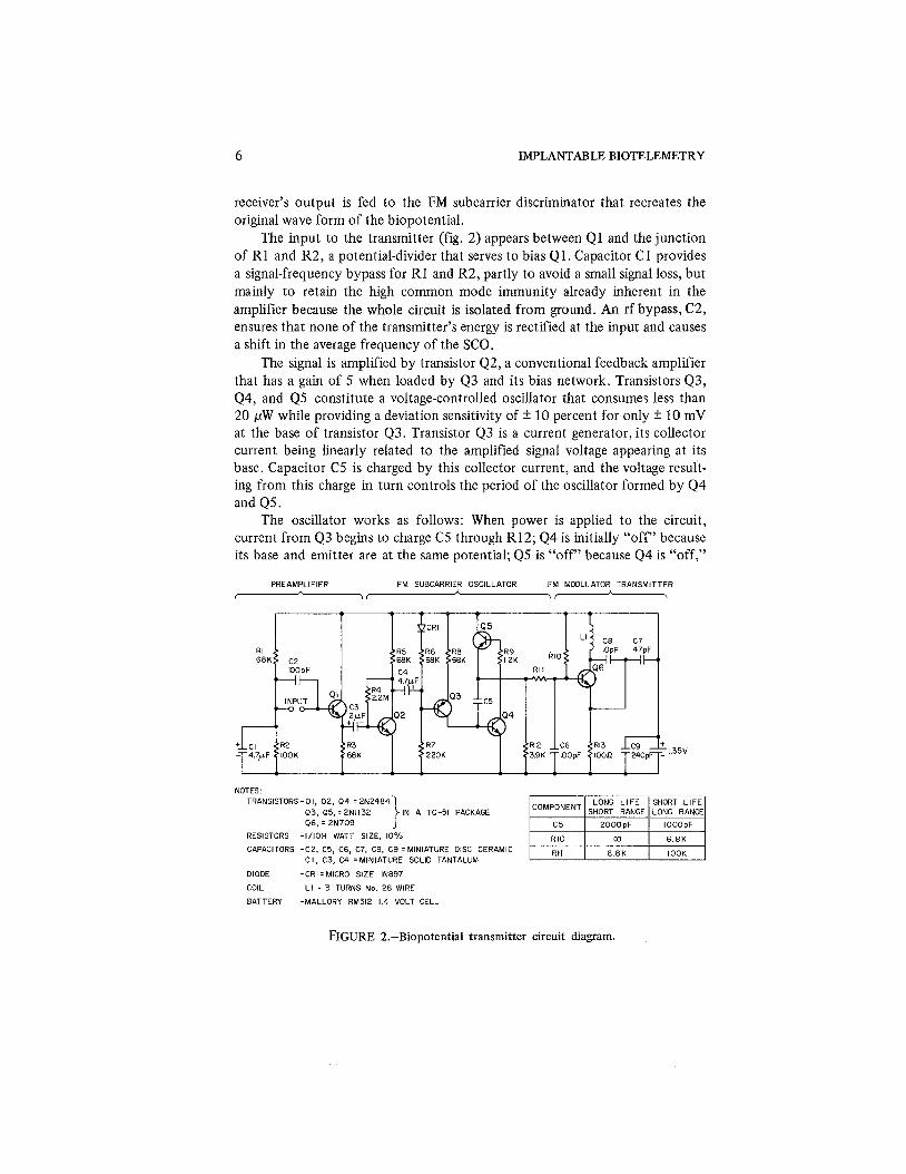
The input to the transmitter (fig. 2) appears between Q1 and the junction of R1 and R2, a potential-divider that serves to bias Q1. Capacitor C1 provides a signal-frequency bypass for R1 and R2, partly to avoid a small signal loss, but mainly to retain the high common mode immunity already inherent in the amplifier because the whole circuit is isolated from ground. An rf bypass, C2, ensures that none of the transmitter's energy is rectified at the input and causes a shift in the average frequency of the SCO.
The signal is amplified by transistor Q2, a conventional feedback amplifier that has a gain of 5 when loaded by Q3 and its bias network. Transistors Q3, Q4, and Q5 constitute a voltage-controlled oscillator that consumes less than 20 pW while providing a deviation sensitivity of * 10 percent for only * 10 mV at the base of transistor Q3. Transistor Q3 is a current generator, its collector current being linearly related to the amplified signal voltage appearing at its base. Capacitor C5 is charged by this collector current, and the voltage result- ing from this charge in turn controls the period of the oscillator formed by Q4 and Q5.
The oscillator works as follows: When power is applied to the circuit, current from Q3 begins to charge C5 through R12; Q4 is initially "off" because its base and emitter are at the same potential; Q5 is "off" because Q4 is "off,"
PREAMPLIFIER FM SUBCARRIER OSCILLATOR FM MODULATOR TRANSMITTER
w, A >-
NOTES : TRANSISTORS-PI, 0 2 , 0 4 = 2 N 2 4 8 4
Q3. 05,: 2N1132 IN A TO-51 PACKAGE 06, : 2 N 7 0 9 1
RESISTORS - l / lOH WATT SIZE, 10%
CAPACITORS -C2, C5, C6, C7, C8, C 9 'MINIATURE DISC CERAMIC C I, C3, C 4 =MINIATURE SOLID TANTALUM
DIODE -CRI = MICRO SIZE IN897
COIL - L I : 3 TURNS No. 2 8 WIRE
BATTERY -MALLORY RM312 1.4 VOLT CELL
FIGURE 2.-Biopotential transmitter circuit diagram.

BIOPOTENTIAL TELEMETRY 7
thereby preventing base-current flow into Q5. The increasing charge on C5 causes the base of Q4 to become increasingly positive until Q4 turns "on,"' which also turns "on" Q5. The positive feedback from the emitter of Q5 to the base of Q4, via C5, causes both Q4 and Q5 to switch "on" in about 1 psec. The transistors remain in this condition for about 10 psec, being held there momentarily by storage-time effects. However, since there is no sustaining current, Q3 and Q4 rapidly turn "off." The time required for charging of C5 to the potential necessary to turn Q4 "on" is about 100 times as long as the "on" time established by storage-time effects. The resulting I-percent duty cycle accounts in part for the low dissipation of power by the circuit. An SCO repetition rate of approximately 1100 Hz is obtained with the component values shown. Transistor Q5 is operated in the inverted connection because the normal configuration provides excessive gain, causing the oscillator to lock in one state; the square wave thus caused to appear at the junction of R12 and C5 is applied to the base of transistor Q6.
Transistor Q6 performs two functions: those of a frequency-modulated rf oscillator and of a transmitter. It is used in a grounded-base Colpitts oscilla- tor circuit, enploying positive feedback to the emitter from a capacitive divider in the collector circuit C7-C8. Inductor L1 serves as both a tuning coil and a transmitting antenna. Frequency modulation is accomplished by varia- tion in the operating point of the transistor, which in turn varies its collector capacitance, thus changing the resonant frequency of the tank circuit. The transmitter's output therefore consists of an RF signal tuned to approximately 90 MHz, frequency-modulated by the SCO, which in turn is frequency- modulated by the input signal.
RECEIVER
The transmitters's output is sensed by a half-wave dipole antenna feeding a conventional, high-sensitivity, FM receiver having automatic frequency control (AFC). The high sensitivity increases the range, helping to overcome the inefficiency of the transmitting-antenna coil, while the AFC ensures that SCO signals are not lost as a result of slight detuning caused by changes in capaci- tance between the transmitter and the biological specimen to which it is attached.
DEMODULATOR
The receiver's output consists of the original SCO signal, which must itself be detected for recovery of the original signal. The original signal is recovered by the SCO discriminator shown in figure 1 for the circuit diagram seen in figure 3.
The impulses from the receiver are coupled to Q1 through the diode network CR2 and CR3; the diodes provide additional bias so that signals less

8 IMPLANTABLE BIOTELEMETRY
NON-LINEAR AMP. MOMTABLE MULTlVlBRATOR FILTER AMPLIFIER
FIGURE 3.-Subcarrier demodulator circuit diagram.
than about I V do not trigger the switching transistorQ1. When transistor Q1 is triggered, it in turn triggers the monostable multivibrator Q2 and Q3. The multivibrator generates a pulse of constant width that is adjusted by means of RP1 to roughly half the interval between successive pulses. The wave form at TP2 is a square wave with an amplitude of 6 V and a deviation in duty cycle proportional to the subcarrier modulation.
Resistor R9 and C7 provide initial averaging of the monostable circuit output, while F1, a low-pass filter with a cutoff of 200 Hz, removes most of the residual ripple. Thus the monostable multivibrator and the filter form a conventional pulse-rate integrator that converts the SCO frequency to a propor- tional voltage and can deliver an output signal varying from 0 to 200 Hz.
Owing to the small deviation, the output of F1 is of the order of tenths of 1 V to adjust the level of the dc output, and to provide a low output impedance. An amplifier with a gain of 10 (consisting of Q5, Q6, and Q7) is incorporated to raise the signal level to the order of 1 V, to adjust the level of the dc output, and to provide a low output impedance.
The demodulator's output therefore has the same wave form as had the original signal that modulated the transmitter. It should be noted that the demodulator circuit is entirely dc so that it does not affect the low-frequency cutoff point of the system.
ALTERNATIVE CIRCUIT
The circuit just described (fig. 2) was designed to provide the range and lifetime required for biomedical transmitters mounted externally on human
BIOPOTENTIAL TELEMETRY 9
subjects exercising etc., or on animals roaming freely within a large room. In many instances, however, one must obtain long-term data from closely confined animals without disturbing them. A modification of the circuit shown (fig. 2) will increase its lifetime with some sacrifice in range of operation.
In the process of adjustment of circuit parameters and reduction of the power required to operate the long-range telemetry unit already described, the average current in Q6 has already been reduced to the minimum practicable level consistent with reliable operation in the 100-MHz band. This limit in current is imposed by the fact that the gain bandwidth product of the tran- sistor decreases at lower current. Since Q6 accounts for a large fraction of the total current required by the circuit, it is obvious that this current must be reduced even further if the operating lifetime is to be increased. The current can be reduced by pulsed operation of Q6. Consideration of the current required by other portions of the circuit shows that operation of Q6 at a pulsed-duty cycle of 1 percent should multiply the lifetime by approximately 25 while reducing the range by a factor of about 10.
The required changes in the circuit for this kind of operation are as follows: R10 is removed, R11 is changed to 6.8 k n , and C5 is changed to 2000 pF. The effect of these changes is to remove the steady bias previously applied to the base of Q6 and substitute a pulsed bias derived from the emitter of Q5. This pulsed bias allows the FM transmitter to oscillate only when a subcarrier pulse is available for transmission; thus the current demand of Q6 is reduced by the duty cycle of the subcarrier pulse.
The use of 2000 pF for C5 in the pulse mode is not essential; it'is used to reduce further the consumption of power. The 1000-pF value for C5 provides a higher subcarrier frequency and consequently better overall frequency response. The 250-Hz and 120-Hz overall frequency responses of these respec- tive systems is more than adequate for the EEG and EKG applications for which they were designed. For such applications as electromyography, greater frequency response may be required and can be attained by further decrease in C5 and consequent increase in the SCO frequency.
SUBCARRIER OSCILLATOR
One salient feature of this transmitter is the SCO that maintains a stable base line unaffected by effects of fluctuating capacitance on the transmitter or by other disturbances in the radiotelemetry link. Use of a subcarrier frequency is standard procedure in most large and sophisticated telemetry systems, but it has often been omitted from miniature systems in the interest of size or econ- omy. Careful design of this transmitter has minimized the total number of components and avoided physically large ones. However, this design is not optimum when greater frequency response is more important than base-line stability; for such situations the SCO Q3, Q4, and Q5 can be eliminated, and

10 IMPLANTABLE BIOTELEMETRY
the amplified signal, such as an electromyogram (EMG), can be applied directly to the RF oscillator Q6 in order to frequency-modulate it. Transistor Q2 should be coupled to Q6 with an emitter-follower to prevent loading of the amplifier Q2.
PERFORMANCE
A photograph of a transmitter having the circuit diagram of figure 2 is shown in figure 4; measurements of its performance appear in table 1.
FIGURE 4.-Assembled transmitter.
TABLE 1 .-Characteristics of a Transmitter's Circuit (figs. 2 and 4 )
Item
Transmitter
Overall system
Parameter
Size Weight Power supply Battery drain Battery life Radio frequency SCO frequency Input impedance
Frequency response Gain Equivalent input
noise Maximum range
Value
0.74 x 0.20 in. (diam, thickness) 2 g RM3 12 Hg cell, 1.4 V 0.8 mA 45 hr (48 days for short-range unit) 90 MHz 11 Hz 20 M a
0.5 to 120 Hz 3000
1 pV rms 100 ft (10 ft for short-range unit)
BIOPOTENTIAL TELEMETRY 11
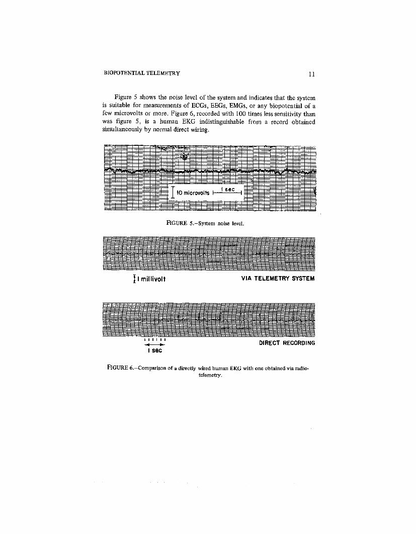
Figure 5 shows the noise level of the system and indicates that the system is suitable for measurements of ECGs, EEGs, EMGs, or any biopotential of a few microvolts or more. Figure 6, recorded with 100 times less sensitivity than was figure 5, is a human EKG indistinguishable from a record obtained simultaneously by normal direct wiring.
FIGURE 5.-System noise level.
1 l millivolt VIA TELEMETRY SYSTEM
I I I I I I - DIRECT RECORDING I sec
FIGURE 6.-Comparison of a directly wired human EKG with one obtained via radio- telemetry.


CHAPTER 3
Temperature Telemetry The physiological parameter of temperature can be measured quite easily
and accurately with thermocouples or thermistors directly connected to a suitable recorder. But, when the measuring system includes radiotelemetry so that conscious and unrestrained animals may be monitored, the problem is considerably more difficult. Since fluctuations in temperature in the body are small in magnitude and slow, a very stable and accurate measuring system is necessary. The thermistor or thermocouple sensor normally used is capable of great accuracy, but its use with a radiotelemetry link often reduces the accu- racy. A system using a thermistor bridge along with a PIM scheme can maintain a high degree of accuracy despite the use of an rf link (refs. 4 and 5).
SYSTEM DESIGN
The complete circuit diagram of the telemetry unit, including sensor, SCO, and transmitter, appears in figure 7. The thermistor, R3, senses the change in temperature, and the resistance change in the thermistor varies the pulse dura- tion of an SCO. The oscillator is an astable multivibrator utilizing two tran- sistors, Q2 and Q3. The period t2 (fig. 8) is determined by the time constant, proportional to R3C2, which is modulated by the temperature of thermistor R3; while t , , a constant, is determined by precision resistor R4 and capacitor C3. Each time the multivibrator switches, a pulse is coupled to the rf stage by Q1 and Q4.
Transistor Q5 and its associated components form an rf oscillator that is tuned in the range 88 to 108 MHz so that an inexpensive commercial FM tuner can be used as a receiver. Transistor Q5 is pulsed "on" periodically by Q1 and Q4 to reduce power consumption and provide long life with a miniature bat- tery. The 2N709 transistor used for Q5 requires a minimum collector current of 0.5 mA for reliable oscillation. The values shown (fig. 7) for components result in typical collector currents of 0.5 to 2 mA.
The average current in the transmitter is greatly reduced by use of pulsed operation: the duty cycle of 20 psec "on" and an average of 10 msec "off' reduces the average current to less than 5 PA; the entire circuit (fig. 7) requires an average current of only 8 to 10 PA.
No provision is made in the circuit for distinguishing between the pulse from Q1 and that from 44, so for identification one must always maintain t2 greater than t l , or vice versa. The 6-MS2 (at 25O C) thermistor and 2-M!2

IMPLANTABLE BIOTELEMETRY
MULTIVIBRATOR SUB-CARRIER WLSED RF OSCILLATOR
FIGURE 7.-Temperature transmitter circuit diagram.
LI ":;pF
- - 3 t - b C6 lOpF
C8 240pF
6.8K
COLLECTOR Q2
A 1.35~A
COLLECTOR Q 3
NOTES: I. R3: THERMISTOR TO MEASURE TEMPERATURE (MAY BE REMOTELY LOCATED) 6M 0 AT 25°C
2. TRANSISTORS: 01 AND 0 4 FSP202 (2N1132 IN A TO51 CASE) 0 2 AND 0 3 FSP8488 (2N2484 IN A TO51 CASE 0 5 FSP239 - I (2N709 IN A TO51 CASE)
3. LI: 3 TURNS NUMBER 28 WIRE APPROXIMATELY 0.7 DIAMETER
FIGURE 8.-Typical circuit waveforms.
COLLECTORS Q I AND Q4
- k t l + k - t 2 - 4
t, a ~ 4 ~ 3 t2 a ~ 3 ~ 2
\ \
TEMPERATURE TELEMETRY 15
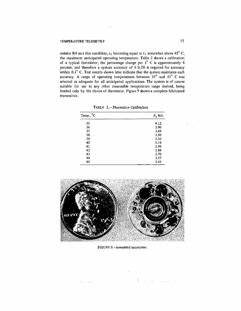
resistor R4 met this condition, t2 becoming equal to t l somewhat above 45" C, the maximum anticipated operating temperature. Table 2 shows a calibration of a typical thermistor; the percentage change per 1" C is approximately 4 percent, and therefore a system accuracy of + 0.2% is required for accuracy within 0.1" C. Test results shown later indicate that the system maintains such accuracy. A range of operating temperatures between 35" and 45" C was selected as adequate for all anticipated applications. The system is of course suitable for use in any other reasonable temperature range desired, being limited only by the choice of thermistor. Figure 9 shows a complete fabricated transmitter.
TABLE 2.- Thermistor Calibration
Temp., OC Rt Ma
FIGURE 9.-Assembled transmitter.
16 IMPLANTABLE BIOTELEMETRY
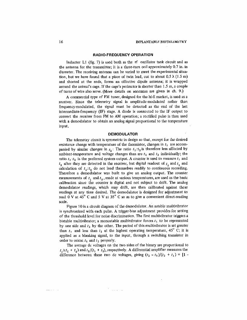
RADIO-FREQUENCY OPERATION
Inductor L1 (fig. 7) is used both as the rf oscillator tank circuit and as the antenna for the transmitter; it is a three-turn coil approximately 0.7 in. in diameter. The receiving antenna can be varied to meet the experimental situa- tion, but we have found that a piece of twin lead, cut to about 0.5 X (1.5 m) and shorted at the ends, forms an effective dipole antenna; it is wrapped around the animal's cage. If the cage's perimeter is shorter than 1.5 m, a couple of turns of wire also serve. (More details on antennas are given in ch. 9.)
A commercial type of FM tuner, designed for the hi-fi market, is used as a receiver. Since the telemetry signal is amplitude-modulated rather than frequency-modulated, the signal must be detected as the end of the last intermediate-frequency (IF) stage. A diode is connected to the IF output to convert the receiver from FM to AM operation; a rectified pulse is then used with a demodulator to obtain an analog signal proportional to the temperature input.
DEMODULATOR
The telemetry circuit is symmetric in design so that, except for the desired resistance change with temperature of the thermistor, changes in t l are accom- panied by similar changes in t, : The ratio t l : t2 is therefore less affected by ambient-temperature and voltage changes than are t l and t2 individually; the ratio t l :t2 is the preferred system output. A counter is used to measure t l and t , after they are detected in the receiver, but digital readout of tl and t , and calculation of t l : t2 do not lend themselves readily to continuous recording. Therefore a demodulator was built to give an analog output. The counter measurements of tl and t , , made at various temperatures, are used as the basic calibration since the counter is digital and not subject to drift. The analog demodulator readings, which may drift, are then calibrated against these readings at any time desired. The demodulator is designed for adjustment to read 0 V at 45" C and 5 V at 35" C so as to give a convenient direct-reading scale.
Figure 10 is a circuit diagram of the demodulator. An astable multivibrator is synchronized with each pulse. A trigger-bias adjustment provides for setting of the threshold level for noise discrimination. The first multivibrator triggers a bistable multivibrator; a monostable multivibrator forces t l to be represented by one side and t2 by the other. The period of this multivibrator is set greater than t l and less than t2 at the highest operating temperature, 45" C; it is applied as a blanking signal, to the input, through a switching transistor in order to orient t l and t2 properly.
The average dc voltages on the two sides of the binary are proportional to t l / ( t l + t,) and t2/( t l t t,), respectively. A differential amplifier measures the difference between these two dc voltages, giving ( t2 - t l ) / ( t2 t t l ) = [l -

TEMPERATURE TELEMETRY
FIGURE 10.-Demodulator circuit diagram.
(tl It2)] / [l + (tl/t2)] which is a function of the stable parameter tl :t2. The function (t, -tl)/(tz + t l ) is a slightly nonlinear function of the variable t2 over a limited range, but, since t2 is also a slightly nonlinear function of temperature because of the thermistor's characteristics, the calibration is nearly linear (table 3). The analog voltage can be adjusted at two points by a gain and zero adjustment to provide a nearly linear direct-reading scale over the range from 35" to 45' C.
TESTS
Table 4 shows the effects of voltage and temperature changes on one of the telemetry units when the thermistor was replaced by a precision resistor. These tests cover extreme variations in voltage and temperature to show the insensitivity of t l :t2 to the variables that normally cause errors; only the thermistor causes significant change in the ratio. The results of a 4-month test of a model circuit (table 5) further confirm the excellent long-term accuracy of the system; the slight variations in the reported values of t l and t, reflect variations in the room temperature when readings were made. (Values of t1 and tz differ in table 5 from those in table 4 because different circuit values were used in an early design.)

18 IMPLANTABLE BIOTELEMETRY
TABLE 3.-Temperature Calibration of Telemetry Unit Before Deep-Body Implantation
Demodulator Temp., OC t1, msec t2, msec tl:t2 output, V
TABLE 4.-Effects of Voltage and Temperature on the Circuit, with Rl Held Constant at 2.4 M i 2
Powei Temp., OC voltage t l , msec t2, msec tl:t2

TEMPERATURE TELEMETRY 19
TABLE 5 .-Results of a 4-Month Test of a Circuit Having a Fixed Resistor for Rt
Time, days tl , msec t2, msec tl:t2
0 2.815 3.009 .9355 4 2.803 2.994 .9362 5 2.812 3.004 .9361 7 2.812 3.004 .9361 8 2.803 2.995 .9358
15 2.812 3.004 .9361 45 2.778 2.970 .9353 82 2.744 2.936 .9346
112 2.765 2.959 .9344

CHAPTER 4
Modified Single-Channel Circuits The circuits described in chapters 2 and 3 represent early designs of
implantable telemetry circuits. The basic operating principles, with SCO's and ratio detection schemes used for reliable and accurate radiotelemetry, are retained in the new systems now to be described. The modified temperature and biopotential circuits reflect refinements and changes to optimize the cir- cuits for specific applications. Although it is highly desirable to have a universal circuit for all measurements of biopotentials or temperatures, one can seldom design a circuit for all applications without compromising some of the charac- teristics. The additional circuits to be described illustrate some of the possible variations on the basic concepts laid down in chapter 1.
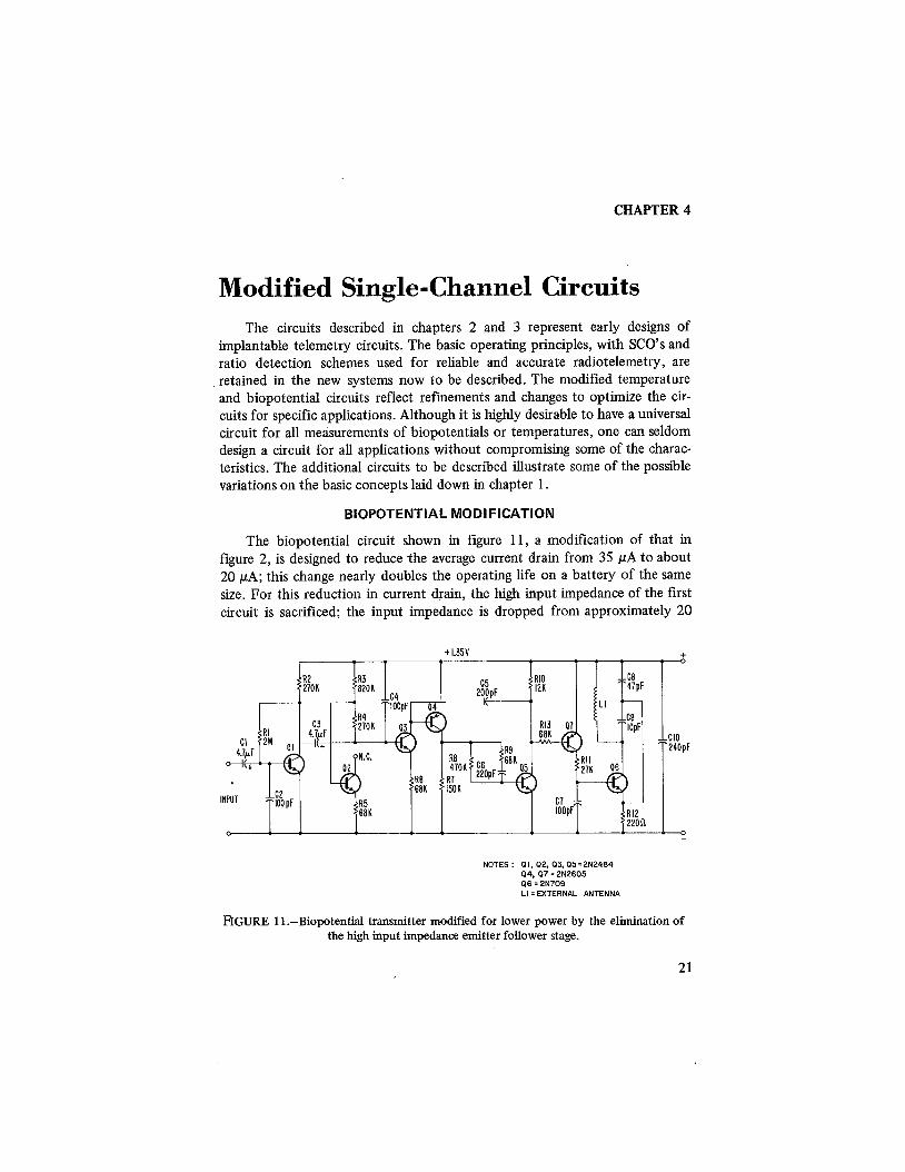
BIOPOTENTIAL MODIFICATION
The biopotential circuit shown in figure 11, a modification of that in figure 2, is designed to reduce the average current drain from 35 pA to about 20 PA; this change nearly doubles the operating life on a battery of the same size. For this reduction in current drain, the high input impedance of the first circuit is sacrificed; the input impedance is dropped from approximately 20
NOTES : PI, 92.03.95 = 2N2484 94. 07 = 2N2605 06 = 2N709 LI =EXTERNAL ANTENNA
FIGURE 11.-Biopotential transmitter modified for lower power by the elimination of the high input impedance emitter follower stage.

22 IMPLANTABLE BIOTELEMETRY
MQ to 150 kS2. Low operating power is most important for implanted devices, but a high input impedance is seldom necessary because the electrodes are internal. The implanted electrodes have a typical source impedance of 100 to 500 a, so an amplifier impedance of 150 k S2is more than adequate,
High-impedance circuits are necessary for external electrodes commonly having an impedance starting at 5 kQ and increasing by a factor of 10 or more, depending on the electrodes, paste, skin conditions, and duration of the test.
Figure 12 shows another variation of the biopotential circuit for further reduction of the consumption of power by sacrificing some of the performance features. The design is exactly the same as in figure 11 except for omission of the first amplifier stage Q1; this omissiori saves about 5 pA of current but increases the typical noise level of 4 qpV peak to peak (fig. 5) to about 15 pV peak to peak. For a 2-to-3-mV EKG signal this noise level is of no consequence, but, if EEG signals, for instance, were to be monitored, this noise level would cause problems. This change shows how these circuits can be modified for improvement of some particular feature such as power consumption, noise level, or frequency response. In the case of figure 12, some of the resistor values also have been altered for reduction of the current, and the frequency of the subcarrier has been lowered from 550 to 330 pulses per second. The decrease in frequency of the sampling rate reduces the frequency response, but the overall system has flat frequency response, f 3 db, out to 100 Hz, which is
INPUT
NOTES: I. Q I . 0 2 , 0 4 = 2 N 2 4 8 4 OR 2 ~ 3 1 2 9 2. 0 3 AND Q 5 = 2N2605 OR NS6201 3. Q6 = 2N709 OR NS9713 4. L I = EXTERNAL ANTENNA
FIGURE 12.-Biopotential transmitter modified for a further reduction in power by the elimination of one amplifier stage. Suitable for high level signals such as EKG at lmv or more but not suited to EEG because of the higher noise level.

MODIFIED SINGLECHANNEL CIRCUITS 23
adequate for most EKG applications. The modifications reduce the average current to 7 pA for figure 12 and to 20 pA for figure 11, with a slight sacrifice in noise level and frequency response.
One must emphasize that the transmitted wave form is identical for all the biopotential circuits, so that the same demodulator circuit (fig. 3) is used with all the transmitters-although, when the subcarrier frequency is altered, corresponding adjustment in the demodulator is required. Figures 11 and 12 show the rf connected for pulse-amplitude modulation only, since they are designed specifically to minimize current consumption; however, the RF tran- sistor in the new circuits can also be operated in the continuous mode of the circuit shown in figure 2.
BIOPOTENTIAL-CIRCUIT DESIGN
The circuit shown in figure 11 operates as follows: Transistor Q1 is used as an amplifier to provide a gain of approximately 5. The ac coupling used provides a lower cutoff frequency of 0.4 Hz. Transistor Q2 is used as a diode to provide temperature compensation for Q3, a constant-current generator that is modulated by the amplified input signal. The astable multivibrator Q4 and Q5 performs the same function as Q4 and Q5 of figure 2 and also puts out the same type of pulsed wave form. Circuit details have been changed for use of types of transistors that are more readily available in microminiature form. The NPN and PNP transistors have been switched in position for application of the proper polarity signal to Q7, the RF stage. The circuit values shown have been adjusted for the high-gain transistors specified: Q4 and Q5. A change in R9 provides an easy method for adjustment of the pulse width, which is sometimes required.
Component values have been changed for a 25-to-35-psec pulse; this change from the 10-to-15-psec pulse, obtained with the circuit of figure 2, is designed to improve the operating range. Standard FM receivers have a band- width limit of 200 kHz; this does not provide an adequate rise time for recep- tion of a 10-to-15-psec pulse. Better signal-to-noise ratio, and therefore more reliable operation under all operating conditions, is obtained with the longer pulse.
The addition of Q7, a saturated switch to couple the astable multivibrator to the rf oscillator 46, adds to improvement of the signal strength because the rf oscillator is not stable during the "pulse-on" period. In fact, the modulation of the rf is such that only a small part of the transmitted pulse may be received on a standard FM receiver having 200-kHz bandwidth. Use of special receivers with wide bandwidths is possible but would not improve the signal-to-noise ratio. The desirable solution is stabilization of the rf so that narrow-band receivers having better signal-to-noise ratios can be used.

24 IMPLANTABLE BIOTELEMETRY
A crystal-controlled rf oscillator would provide great stability, but only with sacrifice in size, economy, and circuit complexity. Transistor Q7 improves the oscillator stability sufficiently so that frequency changes do not exceed the bandwidths of standard FM receivers. The rf oscillator is extremely sensitive to variations in voltage at the base of Q6; these variations change the collector- to-base capacitance and therefore alter the oscillator frequency. This effect is intentionally used for frequency modulation with a continuous carrier (short- life, long-range unit; fig. 2), but this is an undesirable effect in the pulsed mode of operation. The addition of Q7 adds very little to the size of the unit but significantly improves performance. The rf oscillator is unchanged from the original design (fig. 2). The two biopotential circuits (figs. 2 and 11) put out identical wave forms, and the same demodulator (fig. 3) is used for both.
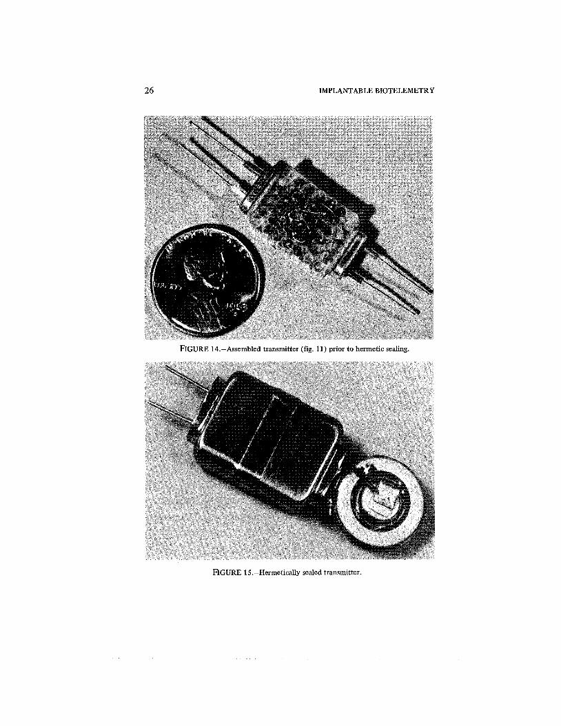
Figure 13 shows all the required components before assembly, and figure 14 shows the assembled transmitter. A cordwood-assembly method is used, which is similar to the circuit construction of figure 4; the rectangular con- struction lends itself to use of a hermetically sealed case with an external antenna. For implant applications, proper sealing of the transmitter is vitally important, and such a case provides the best protection from moisture. Con- struction details and sealing techniques are discussed more fully in chapters 10 and 11. The biopotential transmitter, sealed and ready for encapsulation, is shown in figure 15; in figure 16 it is encapsulated and ready for implantation.
TEMPERATURE TRANSMITTER
Figure 17 shows a modified version of the temperature transmitter; again the modulation scheme is unchanged. Circuit details have been modified for improvement of some operational features but without distinguishable change in the wave form transmitted by the system (ref. 6).
The astable multivibrator Q5 and 4 6 produces a series of pulses with the period between pulses being alternatively tl and t , (fig. 18); each pulse triggers the binary Q1 and Q2 to its opposite stable state. The binary controls the solid-state switches Q3 and Q4 so that after each pulse the "on" condition is switched between Q3 and Q4 alternately. A thermistor is connected to Q3; a fured precision 2-M Slresistor, to 44. Since the oscillator period is controlled by the size of capacitor C4 and its charging current, we now have tl a R7C4 and tz a TC4, where R7 is a calibration resistor and T is the thermistor sensor.
Although the wave forms are'identical with that of figure 8, there is an important difference in that tl and tz depend on a common capacitor, C4, instead of the two capacitors C2 and C3 of figure 7. Thus it is possible for C4 to vary over a moderate range without affecting the ratio tl :t2 (the factor measured by the demodulator) so that the size of the transmitter is reduced, since physically large stable capacitors of materials such as mica or glass are not required. The smallest capacitors, of ceramic, are not always stable enough for

MODIFIED SINGLECHANNEL CIRCUITS 25
FIGURE 13.-Unassembled parts for one biopotential transmitter as shown in circuit dia- gram (fig. l l ) .
good long-term accuracy with the circuit of figure 7. Figure 17 requires only one 4700-pF capacitor, with further saving in size. The old circuit worked best with a matched set of transistors for Q2 and A3 (fig. 7); a matched set is no longer important. The effects of changes in power supply, transistor drift, and capacitor drift are all effectively compensated in the new circuit. The results with the original circuit were very good (tables 2 and 5), but the new circuit is
26 IMPLANTABLE BIOTELEMETRY
FIGURE 14.-Assembled transmitter (fig. 11) prior to hermetic sealing.
FIGURE 15.-Hermetically sealed transmitter.

MODIFIED SINGLECHANNEL CIRCUITS
FIGURE 16.-Sealed and encapsulated transmitter ready for implantation.
even more accurate since pairs of transistors and capacitors do not have to track each other, with the result that selection of components is no longer critical. Tables 6 and 7 show typical results with the new circuit.
The offset voltages that appear across the solid-state switches Q3 and Q4 are a possible source of error in the modified circuit. In order to keep the total current small, a base current of only about 1 PA is applied to the switches. The result is an offset voltage of 20 to 30 mV if selected transistors are used; as high as 70 mV with unselected ones. Temperature tests and long-term measure- ments have shown variations in the offset voltage of less than 1 mV; since this is less than 0.1 percent of the voltage applied to the thermistor, the resultant temperature effect would be very small.
Transistor Q7 is an amplitude-modulated rf oscillator as used in the previously described transmitters. Transistor Q8 improves the frequency

IMPLANTABLE BIOTELEMETRY
I I NOTES:
I.THERMISTOR EXTERNAL TO INTEGRATED CIRCUIT L C 4 - CORNING ELECTRONICS CYK 01 BU 472K 3. INDUCTOR EXTERNAL TO INTEGRATED CIRCUIT 4.COLLECTOR LE4D OF 0 4 TO BE BROUGHT OUT OF INTEGRATED CIRCUIT
FIGURE 17.-Modified temperature t r a n s m i t t e r circuit diagram.
SOLID STATE SWITCH
b8-10 msl k15-25 psec
ASTABLE 1 MULTIVIBRATOR
k t 1 t t 2 1
TRANSMITTER I I I
88-108 MCS R F CARRIER
FIGURE 18.-Typical circuit waveforms.

MODIFIED SINGLECHANNEL CIRCUITS 29
TABLE 6.-Effects of Changes in Power Supply on the Circuit, with R7 and T Held Constant at 2 and 4 M R , Respectively
Supply voltage t 1, msec t 2 , msec t l : t 2
TABLE 7.-Effects of Variations in Temperature on the Circuit, with R 7 and T Held Constant at 2 and 4 M a , Respectively
Temp., OC Supply voltage t 1, msec 12, msec tl : t 2
stability as in the modified biopotential transmitter. Again a 25-to-35-psec pulse is desirable to make effective use of commercial FM receivers and for maximum signal strength. The average current is only 7 pA for the entire circuit, even with a wider pulse.
This transmitter can be packaged with discrete components in a package similar to the biopotential one shown in figure 13. The wafer can be of the same size although enlarged openings for R7 and C4 may be needed, depending on the type and stability of components selected. The temperature circuit also has been constructed by use of hybrid integrated-circuit techniques (fig. 19). (The various construction techniques are more fully discussed in ch. 10.) The size with use of these techniques is approximately 5 X 10 X 20 mm, including hermetic sealing, battery, and antenna.
The demodulator described in figure 10 has been employed with the modified temperature circuit.

30 IMPLANTABLE BIOTELEMETRY
FIGURE 19.-Temperature transmitter (fig. 17) constructed using hybrid integrated cir- cuit techniques.

CHAPTER 5
Pressure Telemetry
The need to measure parameters other than temperature and biopotentials has resulted in development of systems suitable for use with various trans- ducers. Blood pressure is frequently measured, especially during cardiovascular studies. The process of design of a pressure-telemetry system has led to.a general-purpose transmitter suitable for use with any transducer having a strain-gage sensing element. Accelerometers, load cells, and dimension gages are a few of the types of transducers that can be used with the system, in addition to pressure. The system to be described provides for total implantation of a transducer and transmitter in an animal, with no wires penetrating the skin.
TRANSDUCER
The transducer selected is designed for biomedical applications (ref. 7); the electrical sensor inside the pressure cell is a solid-state strain gage. Such a gage
FIGURE 20.-Solid-state strain gage pressure cell transducer.

32 IMPLANTABLE BIOTELEMETRY
is necessary for an adequate signal without great amplification. Figure 20 shows a typical commercially available pressure cell that has been used exten- sively. Strain-gage-type cells. of different sizes and geometries are available commercially to meet specific needs.
CIRCUIT DESCRIPTION
Figure 21 is a circuit diagram of the complete transducer-transmitter system that is implanted in an animal (ref. 8). The circuitry looks very much like those of the biopotential- and temperature-telemetry systems (figs. 11 and 17), since the main functional blocks are identical and the same astable multi- vibrator Q9 and Q10 is used as the SCO. The subcarrier frequency is set at about 600 Hz as used with the biopotential system, providing adequate frequency response for most cardiovascular applications. (The subcarrier frequency can be further increased if the 100-150-Hz upper frequency limit of the system is not adequate.) Typical wave forms of the system appear in figure 22. After each pulse produced by the oscillator Q9 and Q10, the binary ~2 and Q3 is switched to the opposite stable position. The solid-state switches Q1 and Q4 are turned "on" alternately as a result. (This operation resembles that of the temperature transmitter.) Additional switches Q5 and Q6 operating in the inverted mode have been used to yield low offset voltages; the large offset voltages of 20 to 30 mV in the temperature unit would not provide reliable operation with the approximately 5-mV full-scale signal obtained from the pressure cell. Conversely the large current drain required for operation of Q5 and Q6 would not be suited to the ultra-low power requirements of the temperature transmitter.
5000 Q STRAIN GAGE PRESSURE CELl
NOTES: QI -W=NS6065 05-06=2N3129 Q7-Q9 = NS6065 010-012;013=2N3129 011 = 2N709 L I = EXTERNAL ANTENNA
FIGURE 21.-Circuit diagram for a pressure transducer telemetry system.

PRESSURE TELEMETRY 33
STRAIN GAGE BRIDGE STRAIN GAGE BRIDGE BALANCED
CHOPPERED UNBALANCED
STRAIN GAGE 1 r OUTPUT
SUBCARRIER 1 1 [L[L OSCILLATOR
RF - TRANSMITTER kt1 +t2+
tl = t2 t2/tl CC PRESSURE
AT BALANCE tl = t2 AND AS T H E PRESSURE UNBALANCES
T H E BRIDGE ti DECREASES AND t2 INCREASES T H E RATIO
t2/tl IS PROPORTIONAL TO PRESSURE.
FIGURE 22.-Typical circuit waveforms.
The switches Q5 and 4 6 alternately connect the opposite sides of the strain-gage bridge to the amplifier Q 12 and Q 13. If the two sides of the bridge are exactly balanced, the voltage at the base of Q13 remains unchanged during the switching back and forth across the gage; if there is bridge imbalance, however, there is an alternating signal that is amplified and applied to the constant-current generator Q8, thereby modulating the oscillator Q9 and Q10. Since the choppered strain-gage signal is a square wave synchronized with the oscillator, the resultant pulse periods t l and t2 are alternately increased and decreased from the average. The pulse wave forms for both the balanced and unbalanced bridge conditions appear in figure 22.
ACCURACY
The ratio t l :t2 is proportional to the bridge imbalance, which in turn depends on the pressure applied to the transducer. This system virtually elirni- nates any errors in transmission caused by the use of radiotelemetry. Changes in amplitude and frequency in the RF link have no effect on the data. The periods t l and t2 can be transmitted very accurately, and when t l equals t2 it is precisely established that the bridge is balanced. It is assumed that the offset voltages are small and stable; since they are less than 1 mV and stable to an order of 10 pV, no significant error is introduced by the switches. Any drift in the gain of the amplifier 413, Q12, and Q8 affects the constant of propor- tionality between the pressure and the resultant analog output. The system

34 IMPLANTABLE BIOTELEMETRY
provides about the same accuracy as most transducers now used in physi- ological monitoring.
The temperature stability of the transducer and circuitry is not very critical with a totally implanted device since the body temperature varies only a few degrees at most; in other words, the body provides essentially a constant temperature environment.
CALIBRATION
The pressure cell and transmitter must be assembled and calibrated together as a system. Both transducer and transmitter differ considerably from unit to unit in sensitivity. If necessary, external resistors are placed across the strain-gage bridge to bring it near balance, with zero pressure applied to the transducer. Readings of t l and t2 are taken from the pulses obtained at the receiver; it is usually desirable to take them with a digital counter and then to calculate the ratio t l :t2. Since the system is almost linear, five to 10 readings over the operating range are sufficient. The output can be read from the demodulator at the same time for an analog reading. The digital readings provide an absolute value that can be used later for verification of readings from the analog demodulator, especially after adjustments of the demodulator.
The pressure transducer shown in figure 20 is an absolute cell, and this feature is useful for dynamic calibrations which can be made in situ without disturbance of the animal. A change in the barometric pressure (controlled by use of a hyperbaric chamber) allows one to change the output after the system is implanted in an animal. The constant in proportionality between the input- pressure change and the demodulator's output voltage can then be checked at any time. The zero point cannot be checked in this manner; checks to deter- mine the zero reading after implantation must be done with a catheter.
As noted previously the system is especially accurate at the point tl = t2; consequently, zero-pressure reading is accurate if the bridge is balanced at this pressure. Of course the system can be no better than the transducer used. If absolute pressure cells are used, it is essential to recognize that the zero reading will change with the barometric pressure. Therefore, since most physiological pressures are taken relative to atmospheric, a correction must be made for changing barometric pressures.
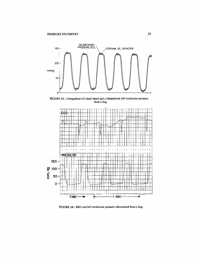
Figure 23 shows a comparison of a telemetered and a hard-wire recording of pressure. Figures 24, 25, and 26 show typical recordings of left-ventricular pressure in a dog; the expanded scale of figure 25 shows the high degree of resolution of the system. Careful calibrations are required for accurate deter- mination of the precise positions of zero pressure on the readout scale.
COMPARISON WITH TEMPERATURE TRANSMITTER It will be noted that the alternate change in pulse intervals tl and t2 , and
in the transmission of data in terms of the ratio tl :t2, is precisely the same as
PRESSURE TELEMETRY
TELEMETERED 150 r PRESSURECELL \ ,STATHAM SF, CATHETER
E[GURE 23.-Comparison of a hard wired and a telemetered left ventricular pressure from a dog.
I l l l l l l l ! i i ! l ! i ! I l l , / / : : -
TIME-+ GLl
FIGURE 24.-EKG and left ventricular pressure telemetered from a dog.

IMPLANTABLE BIOTELEMETRY
TIME- b----- I S ~ C -----4
FIGURE 25.-Expanded pressure scale (from fig. 20) to show the filling of the left ventricle and illustrate the system resolution.
that used for the temperature transmitter. The difference is that the thermistor sensor has sufficient sensitivity (4 percent per OC) so that no additional gain is required. In contrast, the strain-gage element in the transducer may have a change of only 0.5 percent over the entire operating range of 0 to 250 mm. Use of an ac amplifier, that includes the gain of the constant-current generator 48, enables one to obtain a large percentage deviation of the oscillator period with a small percentage change in the bridge.
Another modification is use of R25 for identification of positive and negative pressures. It will be remembered that, in the temperature unit, t2 was always greater than t l over the designed operating range for avoidance of ambiguity. The same method can be used here if the bridge is balanced in such a way as not to cross from plus to minus in the operating range. Because the range of temperature excursions in the body is more predictable than pressure, positive identification to prevent ambiguity is more essential with pressure measurements. Addition of R25 is a simple modification for this purpose, but

PRESSURE TELEMETRY 37
I +I o set+ 1 . 1 1 . l . L . L 1 . 1 . 1 1 . 1 .
1 1 P 1 1 1 1 1 1 1 1 t 1 1 1 1 1 1 1 1 r l )
TIME - FIGURE 26.-Left ventricular pressure taken at a slow chart speed.
is suitable for only the continuous-mode FM transmitter-not for the low- power pulsed mode of operation (fig. 17). Resistor R25 couples a low-level square-wave signal,(synchionous with the solid-state switching, figure 22) to the base of Q11; this signal in turn causes frequency modulation of the RF that can be picked up in the receiver, demodulated, and used for identification of polarity.
DESIGN CONSIDERATIONS
The power consumption of the strain gage is so great relative to those of the temperature and biopotential units already described that there is not much advantage in running the rf in a pulsed mode. In the biopotential unit the current was dramatically reduced from 0.8 mA to 20 pA by the pulsed mode of operation. Although the pressure circuit, excluding the rf stage, consumes only 25 pA of current, the transducer consumes 300 pA. The circuit diagram (fig. 21) shows the rf stage connected as a continuous carrier with EM; this has been the principal mode of operation, although pulsed-mode circuits have performed satisfactorily in the same manner as the pulsed temperature and biopotential units. The pulsed mode will be very good in some

38 IMPLANTABLE BIOTELEMETRY
applications, especially with higher-impedance transducers. Reduction in transducer power by an order of magnitude by use of higher-impedance solid- state strain gages is well within the present state of the art.
Although the pressure transmitter is comparable in size to the temperature and biopotential units, the size of the transducer limits application of the system to large animals such as dogs, especially if cardiovascular measurements are to be made. Smaller transducers are becoming available that will allow use in small animals. The problem of heavy power consumption is alleviated by use of magnetic and rf-controlled switches that allow intermittent operation with resultant conservation of power. (Remotely controlled switches are more fully discussed in ch. 8.) Most experiments do not require continuous data; a system drawing 1 mA of current (fig. 21) will collect data intermittently for many years.
A completely sealed and potted unit, ready for implantation, is shown in figure 27; figure 28 is a pictorial view of the system with the major compo- nents identified. The system implanted in a dog is shown in an x-ray photo- graph (fig. 29). Sealing and encapsulation techniques are more fully discussed in Chapter 11 . The following list summarizes the significant performance characteristics of the system; operating life is not shown since it depends on
5
the Size of battery used.
FIGURE 27.-Sealed and encapsulated pressure transmitter system ~eady for surgical implantation.

PRESSURE TELEMETRY
PRESSURE CELL 5 0 0 0 G STRAIN GAGE SENSOR HERMETIC FEED THRU
C HERMETIC
HERMETICALLY SEALED CASE
S I L A S T ~ TUBING \ STRAIN GAGE BALANCING MEDICAL GRADE RESISTOR
FIGURE 28.-Pictorial diagram of the pressure telemetry system.
FIGURE 29.-X-ray of a pressure system implanted in a dog.
IMPLANTABLE BIOTELEMETRY
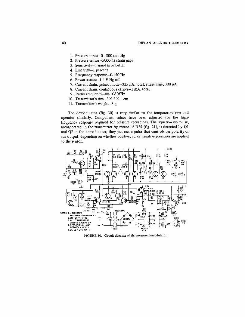
1. Pressure input-0 - 300 mrn-Hg 2. Pressure sensor-5000- Q strain gage 3. Sensitivity-1 mm-Hg or better 4. Linearity-1 percent 5. Frequency response-0-150 Hz 6. Power source-1.4-V Hg cell 7. Current drain, pulsed mode-325 PA, total; strain gage, 300 PA 8. Current drain, continuous carrier-1 mA, total 9. Radio frequency-88-108 MHz
10. Transmitter's size-3 X 2 X 1 cm 1 1. Transmitter's weight-8 g
The demodulator (fig. 30) is very similar to the temperature one and operates similarly. Component values have been adjusted for the high- frequency response required for pressure recordings. The square-wave pulse, incorporated in the transmitter by means of R25 (fig. 21), is detected by Q1 and Q2 in the demodulator; they put out a pulse that controls the polarity of the output, depending on whether positive, ac, or negative pressures are applied to the sensor.
FIGURE 30.-Circuit diagram of the pressure demodulator.

CHAPTER 6
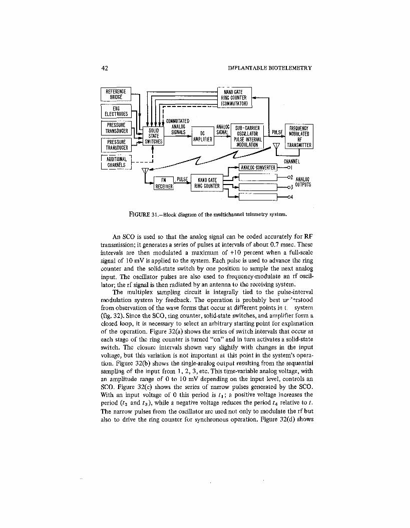
Multichannel Telemetry Systems Multichannel systems have been developed so that various physiological
parameters can be monitored simultaneously. Although several single-channel transmitters can be used in an animal, this approach is impractical if many channels are required; for more than three or four parameters, a multichannel transmitter is more suitable. The overall size is reduced by elimination of multiple rf stages and antennas, and only one receiver is required. The added complexity of a multiplex system must be weighed against the possible simplicity in the rf operation.
The system to be described has the features essential to an implantable system: small size and low power consumption. A time-sharing multiplex sys- tem is used to sample the outputs of a group of sensors; it accepts inputs from a wide variety of sensors such as EKG electrodes, thermistors, and strain-gage pressure cells. The system is versatile not only in regard to the type of sensor used but also because the number of channels can be varied from three to 10 (ref. 9).
SYSTEM
The upper section of figure 3 1 shows the implanted-transmitter portion of the system; the lower part shows the receiving and demodulation equipment that provides an analog signal suitable for input to a pen recorder. In basic operation this circuit resembles the single-channel circuits that have been described, except for the addition of multichannel capability by means of a commutating switch.
TRANSMITTER
The ring counter is the key element in the operation of this multichannel transmitter. A nand-gate ring counter is used as a commutator to operate sequentially a series of solid-state switches (one for each input channel). The physiological parameters to be measured are sensed by such devices as EKG electrodes or strain-gage-type pressure cells. The system is designed to operate with an input of about 10 mV full-scale to match the output level of the strain-gage sensors used. The cornmutated analog signal is amplified by a gain of about 10 before it is applied to an SCO.
42 IMPLANTABLE BIOTELEMETRY
FIGURE 31.-Block diagram of the multichannel telemetry system.
An SCO is used so that the analog signal can be coded accurately for RF transmission; it generates a series of pulses at intervals of about 0.7 msec. These intervals are then modulated a maximum of + l o percent when a full-scale signal of 10 mV is applied to the system. Each pulse is used to advance the ring counter and the solid-state switch by one position to sample the next analog input. The oscillator pulses are also used to frequency-modulate an rf oscil- lator; the rf signal is then radiated by an antenna to the receiving system.
The multiplex sampling circuit is integrally tied to the pulse-interval modulation system by feedback. The operation is probably best ur 'prstood from observation of the wave forms that occur at different points in t system (fig. 32). Since the SCO, ring counter, solid-state switches, and amplifier form a closed loop, it is necessary to select an arbitrary starting point for explanation of the operation. Figure 32(a) shows the series of switch intervals that occur as each stage of the ring counter is turned "on" and in turn activates a solid-state switch. The closure intervals shown vary slightly with changes in the input voltage, but this variation is not important at this point in the system's opera- tion. Figure 32(b) shows the single-analog output resulting from the sequential sampling of the input from 1, 2, 3, etc. This time-variable analog voltage, with an amplitude range of 0 to 10 mV depending on the input level, controls an SCO. Figure 32(c) shows the series of narrow pulses generated by the SCO. With an input voltage of 0 this period is t l ; a positive voltage increases the period (t2 and t 3 ) , while a negative voltage reduces the period t4 relative to t. The narrow pulses from the oscillator are used not only to modulate the rf but also to drive the ring counter for synchronous operation. Figure 32(d) shows

MULTICHANNEL TELEMETRY SYSTEMS
( a d 2 RING COUNTER 5 COMMUTATI NG a
SIGNAL 3 4 2.7V OFF O V ON
(b) COMMUTATED
ANALOG SIGNAL 0 FULL SCALE LVMMU I A I tU
ANALOG ?'*"^'
(C) PULSE INTERVAL
MODULATED SUBCARRIER -
t a ANALOG INPUT SIGNAL
FREQUENCY MODULATED h h RF CARRIER
FIGURE 32.-System waveforms in the transmitter.
the frequency modulation (Af) of the rf carrier used to convey the pulse-interval information to the receiving station.
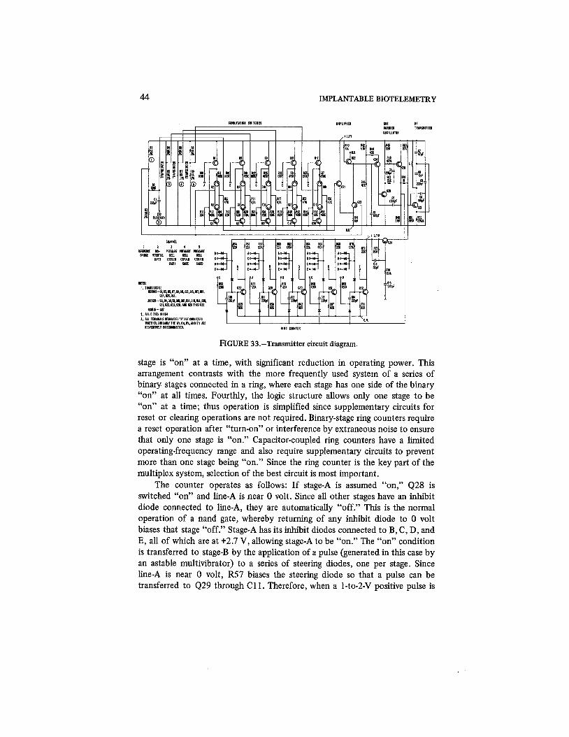
CIRCUIT
Although the circuitry required for this modulation appears complex (fig. 33) because of the many components, many of the subsections are repetitive. The circuit is best described by separate treatment of the operation of each subsection. The major subsections are the ring counter, solid-state switches, signal conditioner, SCO, and rf transmitter.
The ring counter is formed by interconnecting a number of nand gates (ref. 10). One gate operates each input switch, so that five gates are required for the five-channel unit shown. Nand gates connected as shown offer a number of desirable features. First, they require very little power per stage and tolerate a wide range of resistance values such as may be necessary for accom- modation of varying requirements of the system. Secondly, the use of nand gates makes the system amenable to use of either off-the-shelf integrated circuits or special hybrid construction. Resistance values can be adjusted to match construction techniques and power requirements. Thirdly, only one
44 IMPLANTABLE BIOTELEMETRY
FIGURE 33.-Transmitter circuit diagram.
stage is "on" at a time, with significant reduction in operating power. This arrangement contrasts with the more frequently used system of a series of binary stages connected in a ring, where each stage has one side of the binary "on" at all times. Fourthly, the logic structure allows only one stage to be "on" at a time; thus operation is simplified since supplementary circuits for reset or clearing operations are not required. Binary-stage ring counters require a reset operation after "turn-on" or interference by extraneous noise to ensure that only one stage is "on." Capacitor-coupled ring counters have a limited operating-frequency range and also require supplementary circuits to prevent more than one stage being "on." Since the ring counter is the key part of the multiplex system, selection of the best circuit is most important.
The counter operates as follows: If stage-A is assumed "on," Q28 is switched "on" and line-A is near 0 volt. Since all other stages have an inhibit diode connected to line-A, they are automatically "off." This is the normal operation of a nand gate, whereby returning of any inhibit diode to 0 volt biases that stage "off." Stage-A has its inhibit diodes connected to B, C7 D, and E, all of which are at +2.7 V, allowing stage-A to be "on." The "on" condition is transferred to stage-B by the application of a pulse (generated in this case by an astable multivibrator) to a series of steering diodes, one per stage. Since line-A is near 0 volt, R57 biases the steering diode so that a pulse can be transferred to Q29 through C11. Therefore, when a 1-to-2-V positive pulse is

MULTICHANNEL TELEMETRY SYSTEMS 45
applied, Q29 turns "on," line-B goes to near zero, the inhibit diode connected to line-B, in stage-A, causes Q28 to turn "off," and line-A then returns to 2.7 V. Line-B is now "on7' and all others are "off." Similarly after the next pulse, line-C is turned "on," etc.
The switching between input channels is accomplished by a series of balanced solid-state switches; 4 2 and Q3 are a typical pair used to switch channel-1. When line-A is near zero, transistors Q1 and 4 4 are turned "on" and activate the switch. Since full-scale subcarrier deviation is achieved with a 10-mV input, the input bridges must be closely balanced. The switching tran- sistors are operated in an inverse mode to provide low offset, and a pair of NPN and PNP types is used to prevent switching currents from unbalancing the input bridge. The voltage level at the junction of R1 and R3 is transferred by the switch to a differential amplifier, 421 and Q23. The amplifier is arranged to take the voltage difference between the reference bridge R1 and R3 and the particular channel that is switched in. Of course, when channel-1 is "on," the amplifier input is effectively shorted by the switch, and a zero calibration results. As the ring counter progressively activates line-B, -C, etc., the appropri- ate switch and input bridge are connected to Q21 and Q23. Transistor Q22 is used as a bias diode to allow direct connection of the amplified signal from the collector of Q23 to the base of the.constant-current generator Q24. The input- voltage level then determines the current generated by Q24 which in turn modulates the period of the SCO 425 and Q26.
The rf oscillator Q27 is modulated by the subcarrier signal through R49. The change in bias voltage, introduced by R49, changes the base to collector capacity, causing modulation of the RF. The frequency deviation is adjusted to approximately +lo0 kHz (by proper selection of R49) to match the capabili- ties of the discriminators on standard receivers. Figure 34 shows an oscillo- scope trace of the SCO signal as obtained from the discriminator in the receiver; every fifth pulse is made longer to allow frame synchronization. This increased pulse length is obtained from Q3 by modulating the RF transmitter via R51.
DEMODULATOR
The train of pulses (fig. 34) from the radio receiver is applied to the demodulator input (fig. 35). A ring counter, similar in operation to that used in the transmitter, sorts the signals. For synchronization the received pulses are integrated by C3. The value of C3 is chosen so that the critical bias level of Q3 is not reached during the normal 20-psec pulse time, but is reached when the long 80-psec synch pulse is present; Q3 then turns "on" and momentarily shorts the collector of Q4 to ground. This grounding forces the ring counter to the first position. If the counter is already in position, the momentary shorting of the collecto; of 4 4 has no effect, since the collector of Q4 is already

46 IMPLANTABLE BIO'lXLEMETRY
FIGURE 34.-Oscilloscope tracing of the subcarrier waveform seen at the output of an FM radio receiver.
FIGURE 35.-Demodulator for the conversion of the pulse signals (fig. 34) into an malog output signal (such as fig. 37).

MULTICHANNEL TELEMETRY SYSTEMS 47
grounded. The synch circuit is always operating then, but is effective only when initial synchronization or resynchronization after noise disturbances is required. A saturating switch, Q5 (operated by Q4), is incorporated in the circuit to provide a low-impedance output to drive the analog demodulator.
A typical demodulator (connection for channel-1) is shown in figure 35. There are five demodulators, one per channel, with a different set of switch lines connected to each one. The various interconnections for each channel are shown at bottom right (fig. 35). The wave forms that occur during the demodulation are shown in figure 36. Operation of the typical demodulator (shown for channel-1) is as follows: Q1 is turned "on" by line-1; this then turns "on" the constant-current generator Q3. A diode is used for temperature compensation. Resistor R5 is a feedback resistor that stabilizes the constant- current generator at a prescribed level. The constant current from 4 3 is used to charge capacitor C1 during the interval when line-1 is "on." The wave form on capacitor C1 is shown in figure 36. The capacitor is charged linearly, and the final voltage obtained depends upon the duration of the pulse from line-1. The charging current and the capacitor size are adjusted for about 3 V during the normal 0.7 msec between pulses. Since the system is designed for a maximum modulation of 10 percent, the variation in the output is 0.3 V (10 percent of 3 V). A high-input-impedance emitter-follower, Q4 and Q5, is used to detect this voltage with a minimum loading effect on capacitor C 1. The capacitor holds its
I CYCLE OF JC-- COMMUTATION -4 SUBCARRIER I
PULSE TRAIN
I I 1 1 1 1 2 3 4 5
, 1 fl2L EQUALS THE DEMODULATED ANALOG VOLTAGE
H CHARGE HOLDING INTERVAL ANALOG
CHANNEL 3 s VOLTAGE SAMPLING
INTERVAL
H-4 4
FIGURE 36.-System waveforms in the demodulator.
48 IMPLANTABLE BIOTELEMETRY
charge after switching of the ring counter from line-1 to line-2. Now the switching transistor Q8 is turned "on7' by line-2, and the voltage is transferred to a storage capacitor, C2, during the sampling interval S. For prevention of loading of capacitor C2, another emitter-follower is used to provide a low- impedance analog output suitable for recording. After the integrated voltage on capacitor C 1 has been transferred to C2, the charge on C 1 must be removed for measurement of the analog voltage during the next frame. Capacitor C1 is discharged by Q2 when line-4 is activated. Corresponding charge, discharge, and sample-and-hold operations for the other channels are shown in figure 36.
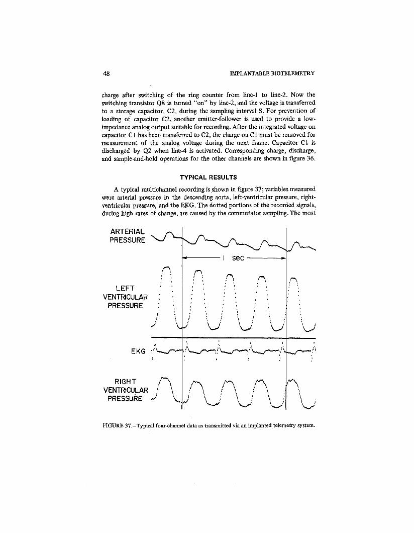
TYPICAL RESULTS
A typical multichannel recording is shown in figure 37; variables measured were arterial pressure in the descending aorta, left-ventricular pressure, right- ventricular pressure, and the EKG. The dotted portions of the recorded signals, during high rates of change, are caused by the commutator sampling. The most
ARTERIAL PRESSURE
LEFT VENTRICULAR
PRESSURE
EKG
RIGHT VENTRICULAR
PRESSURE ,
FIGURE 37.-Typical four-channel data as transmitted via an implanted telemetry system.
,A, , I '
# .
, 8
' ,
1
I I
I.
J'
, t
\
2 0 LJ
I I sec *
r! . , ' , ' ,
:? 8 9 , I
/I , I
I
I ' , I I
0 8 0 I
' , I I . 1
' I I ,
0 > , 0
' I
I ' ( b I , , ' ; :u; 8uo ;u:
L..J-"?i*,;-)-,:L-: $
,
r! 0 a I I
1 ,
6 a
:u I \
:? L

MULTICHANNEL TELEMETRY SYSTEMS 49
FIGURE 38.-Comparison of telemetered and hard wired pressure waveforms.
rapid rate of change that can be recorded is, of course, limited by the sampling rate. Figure 38 compares hard-wire and telemetry recordings of left-ventricular pressure. The limitation due to the sampling rate is readily apparent; otherwise the two recordings are nearly identical.
As previously explained, one channel of the transmitter is used as a reference or calibration channel, the input to which is a resistance bridge without physiological data or modulation applied. Any variation in the output level of this channel can be attributed to a drift in the SCO or dc amplifier associated with it, since the possibility of error in the solid-state switch is small because of the low offset and inverse mode of operation. The SCO and dc amplifier are common to all channels, so that any drift affects both of them equally. Compensation is then obtained by using the differential input of a recorder and taking the difference between the output of channel-1 and each data channel. The problem of elimination of the large 3-V offset in the output is accomplished by this same technique. The sensitivity of the recorder can then be adjusted for a full-scale excursion for the 0.3-V demodulator output.
FREQUENCY RESPONSE AND NOISE LEVEL
The system has been checked with a variety of test signals (fig. 39). These data were taken on an eight-channel transmitter, with test data recorded on one channel; the result of the application of a sine-wave input, varying from 10 to 50 Hz, is shown. The frequency response is flat until the input approaches 50 Hz, where an aliasing error is introduced by interference between the sampling rate and the input frequency. Large-amplitude, high-frequency sine waves are not typical of biomedical signals; biomedical voltages are typically
IMPLANTABLE BIOTELEMETRY
10 20 30 40 50 Cps SWEPT SINE WAVE
I CpS TRIANGULAR WAVE 10 CpS TRIANGULAR WAVE
I0 CpS SQUARE WAVE
FIGURE 39.-Various test waveforms after transmission through the system.
low-repetition-rate impulses characterized by a series of harmonics decreasing in amplitude at higher frequencies. The square-wave and triangular-wave responses at 1 and 10 Hz better illustrate the capabilities of the system for its intended use; the 1- and 10-Hz triangular waves are faithfully reproduced and show the linearity of the system. The transient response of the system is shown with a 10-Hz square wave. The sampling rate, approximately one reading every 3.5 msec, limits the response time. If the step function occurs during the sampling period, a notch can be noted in the step function; then, with the next sample, full voltage is reached. The 10-Hz triangular wave also shows small steps corresponding to the sampling rate.
Figure 40 shows simultaneous recordings from three adjacent channels of an eight-channel system. The central channel has a full-scale (10-mV) sine-wave signal applied; the sensitivity of the adjacent channels has been increased tenfold for demonstration of the noise limitations of the system. The noise is less than 20 pV peak to peak, including any cross-modulation that may result from a full-scale signal on the central channel. Cross-modulation is a common problem in multichannel systems; its elimination is important for yield of accurate and faithfully reproduced data (see table 8).

MULTICHANNEL TELEMETRY SYSTEMS 5 1
FIGURE 40.- Test to demonstrate the almost complete elimination of cross channel modulation. A high level signal (10mv p p ) on the center channel and shows no
effect on boosted sensitivity adjacent channels.
TABLE 8.-Performance Characteristics of Multichannel Telernetiy System
Characteristic Performance
Number of channels
Sampling rate Frequency response Transient response Input impedance
Noise level
Systems with five and eight channels have been tested, but the system can easily be adapted for more or less channels. -0.7 msec per channel dc to 50 Hz 5 to 7 msec for fivechannel system Suitable for 5-kn strain-gage bridges, or approximately 150 k n in use with biopotentials such as EKG's
Less than 200 pV peak to peak, including cross modula- tion
Radio frequency 88 to 108 MHz
Power supply 2.7 V (two Hg cells)
Battery drain
Operating life
Size
Approximately 2.5 mA for the transmitter system (The total current required by the three pressure cells and reference bridge used in this instance is 1 mA.)
200-hr continuous operation with two 500-mA-hr bat- teries (fig. 41)
Transmitter (independent of battery and transducers), about 1 by 2 by 8 cm
Weight Transmitter, 70 g [two 500-mA-hr Hg cells (pacemaker type), 16 gl

5 2 IMPLANTABLE BIOTELEMETRY
COMPLETED TRANSMITTER
Figure 41 is a photograph of the complete transmitter system, with three pressure cells and one pair of EKG electrodes. The pressure cells are connected to the transmitter with medical-grade Silastic tubing. The hermetically sealed transmitter is coated with Silastic for good compatibility with body tissue. Two 500-mA-hr batteries are used; they are sealed in wax and then coated with Silastic. Connected to the battery is a magnetic latching switch for turning the transmitter "off' when data are not being taken; the switch is placed just under the skin and can be operated by a nearby magnet. More details on sealing are given in Chapter 1 1.
FIGURE 41.-Encapsulated transmitter, power supply, and transducer system ready for surgical implantation.

CHAPTER 7
Multichannel Temperature Transmitter
The general-purpose multichannel transmitter (ch. 6), suitable for use with a wide variety of transducers, has been modified to meet the specific requirements of a temperature transducer (ref. 11). The modification simplifies the system, allowing it. to be smaller and use less power for this type of transducer. In addition to meeting a specific need, this modification shows how the circuit designs can be altered for special requirements without change in operation of the basic system. In this case, size and power consumption have been reduced by sacrifice in ability to use a variety of transducers.
CIRCUIT DESCRIPTION
The multichannel temperature transmitter (fig. 42) shows similarities to the general-purpose transmitter (fig. 33). The nand-gate ring counter is identical except for the resistance values; all resistance values in the ring counter have been scaled up for a reduction in current drain. For a thermistor transducer, a single transistor such as Q6 can be used as a switch in place of the more complex balanced switch used in figure 33. The 4 percent/°C sensitivity of the thermistor allows one to eliminate the dc ampflifier and go directly into the astable multivibrator Q12 and Q13. The transmitted wave form is a series of pulses with the interval between them proportional to a fixed resistor or to the impedance of the thermistor being sampled.
A comparison of the temperature-telemetry circuits of figures 42 and 17 is also very pertinent. The rf and astable multivibrators are made identically. The switching transistors Q6-Q10 also are identical except that there are five of them instead of only two. The temperature circuit (fig. 17) had a bistable circuit for switching between two inputs, while the multichannel uses a ring counter to provide five positions. A 2-M Clreference resistbr is used on one channel, as before, to provide calibration and accuracy. Substitution of a five-position counter for a two-position counter is the only difference.
The channel is identified by the same means as in the single-channel temperature unit. The reference resistor R28 is set at a lower value than any of the thermistors will reach at maximum temperature. This procedure can be used since temperature changes are very small and the maximum range is very predictable; it is impossible on the general-purpose multichannel unit since the level of the input signal cannot be anticipated accurately.

IMPLANTABLE BIOTELEMETRY
2.510.47001l TIPL CYMIIT471X LQt-~~.01112*. 0~-~,0.*1110(1s 4 TI-14 TIILRY8ITOI 5YTL I r lr C n. DIODES. I L L ,".,I,
FIGURE 42.-Circuit diagram of multichannel temperature transmitter.
The functioning of the ring counter is identical with the description in Chapter 6 . The collector resistor is changed from 22 to 270 kS2 for significant reduction in current drain; all other associated resistors have been scaled proportionally. The rf stage is also run in the pulsed mode for the very low operating power.
DEMODULATOR
Since the transmitter works in the pulsed mode, amplitude detection is needed on the receiver as with the single-channel systems. The temperatures can be accurately determined with an electronic counter; if the recording is to be continuous, an analog demodulator is required. A demodulator similar to that in figure 35 can be used, but the method of synchronization must be changed. A method similar to the one used for the single-channel temperature circuit must be used.
PERFORMANCE
This system has the advantage of operation on only one battery cell (1.34 V) instead of the two required for the general-purpose system. Circuit adjustments and pulsed operation have reduced the current drain from 1.5 mA to 27 yA, so that the system is useful for long-term measurements. The operation is limited, though, to the use of thermistors or similar, high-output sensors. Figure 43 shows the transmitter prior to final assembly. The final construction and sealing resemble similar steps for the pressure and multichannel units.

MULTICHANNEL TEMPERATURE TRANSMITTER 55
FIGURE 43.-Fabrication of the circuit (fig. 42).

CHAPTER 8
Power Sources and Switches
A key compofient in a biotelemetry system is the power source. It is both the largest component (usually determining the size of the transmitter) and the one most liable to fail. Transistors, resistors, etc., have been developed to such a point that one can predict statistically the mean time between failures (MTBF) in from millions to hundreds of millions of hours. Since the most complex system described has no more than a few hundred components, reli- able operation for many years can be expected from aproperly designed and constructed electronic circuit. The component that frequently falls short of its stated operating life is the battery.
The electrochemical battery has been the principal source of power for biotelemetry systems. Atomic power, rf-energy beams, body electrodes, rechargeable batteries, mechanical converters, etc., are other possible energy devicgs that should be considered in any comprehensive search for new power sources. Most of these devices remain insufficiently developed for reliable long- life sources of energy, but they should not be neglected for the future.
ELECTROCHEMICAL BATTERIES
Batteries are traditional sources of power for portable electronic equip- ment. An amplifying device such as a vacuum tube requires considerable heater power, but the advent of transistors greatly lowered requirements. Recently, very small batteries have been developed by industry for use in wrist watches and hearing aids. These devices are in mass production, which offers many advantages, not only in cost but also in the availabi!ity of large consistent samples for reliability testing. On the basis of the high potential market that prompted industry to expend great sums on development of these batteries, the development costs per unit are very low; development of special energy sources for implantable telemetry would be very expensive because of the limited demand. Thus our selection has been limited to off-the-shelf batteries (ref. 12).
Table 9 lists the electrical and mechanical characteristics of some of the batteries we have found most useful. Two general types, silver oxide and mercury, have been used. Manufacturers rate the shelf life of the mercury cell longer than that of the silver oxide, but both are suitable $or implantable telemetry systems. Since long operating life with very low current drain is required, shelf life is a most important characteristic.

TAB
LE 9
.-Sp
ecifi
catio
ns
of S
ome
Bat
teri
es U
sefu
l for
Im
plan
ted
Tel
emet
ry S
yste
ms
VI
00
Typ
e Se
rvic
e M
ax.
Dia
ml
life,
cu
rren
t W
eigh
t, he
ight
, m
A-h
r dr
ain,
mA
g
cm
Che
mis
try
Com
men
ts
RM
212
16
0.75
0.
28
0.55
10.3
1 H
g St
anda
rd-t
ype
Hg
cells
S13E
6
0
3 1.
0 0.
7710
.5
Silv
er o
xide
; KO
H e
lect
roly
te
Mad
e fo
r he
arin
g ai
ds;
1-yr
she
lf li
fe
E30
1 10
0 0.
1 1.
68
1.15
10.3
3 Si
lver
oxi
de; N
aOH
ele
ctro
lyte
Mad
e fo
r w
rist
wat
ches
; 2-y
r sh
elf
life
W1
36
0.5
0.56
0.
7710
.34
Hg
Lon
g-lif
e H
g ce
lls d
evel
oped
for
wat
ches
W3
165
1 2.
24
1.15
10.5
WH
4 10
0 1
1.4
1.15
10.3
3 Im
prov
ed s
eal o
ver W
4
RM
CC
640W
50
0 1.
5 7.
9 1.
611.
1 D
evel
oped
for
hig
h-re
liabi
lity
pace
mak
er u
se; s
imila
r !!?
to
the
RM
64O
and
RM
1, b
ut w
ith
low
er c
urre
nt r
atin
g 3
and
long
er s
helf
lif
e i-
RM
CC
-1W
10
00
2 12
1.
611.
63
4 f
POWER SOURCES AND SWITCHES 59
The RM312 (mercury) and S13E have been the principal batteries used with the single-channel pulsed EKG and temperature transmitters. The RM312 is rated at 36 mA-hr, the S13E at 60 mA-hr. They are the same in diameter (0.310 in.), but the S13E is slightly thicker: 0.210 in. versus 0.135 in. Since the electronics package is approximately 0.2-in. thick, the S13E fits the package just as well as the RM312 and provides 50 percent more life. The S13E, designed for hearing aids, has a slielf life of 1 year (with about 80 percent of its life remaining) because of a KOH electrolyte; this shelf life is compatible with the lowest-powered circuit, the pulsed temperature trans- mitter, that draws 7 pA and has a theoretical life of 8500 hours or about 1 year.
Since an experiment using an implanted system must be terminated, with attendant physiological shock, unless the battery is replaced, a realistic estimate of the operating life is essential. A conservative estimate is based on 50 to 75 percent of the theoretical life because of the effects of elevated body tempera- tures and unknown conditions of storage prior to use. With the temperature unit and an S13E cell, 6 to 9 months of reliable operation is possible.
To ensure the best possible chance of uninterrupted operation, the largest battery is used that the research situation will allow; thus batteries such as the RM657, S301, and S303 are frequently used. The larger batteries have better seals, so that the electrolyte is less likely to leak. The S301 and S303 are both silver oxide cells with a NaOH electrolyte and a 2-year shelf-life rating. The manufacturer estimates the life of the S301 at 19.7 months with a current drain of 7 pA at 95O F; ratings at elevated temperatures are usually difficult to find, but, since this cell is designed for watches, performance at low currents and elevated temperatures is pertinent.
The multichannel transmitter is normally operated with larger batteries because of the relatively heavy current drain of 1 to 2 mA; RMCC640W and RMCC-1 W certified cells designed for pacemaker application are normally used. This is an example of cells, highly developed and tested for different purposes, that can be applied to biotelemetry; they are mercury cells, but special process-control and testing raise the reliability much higher than normal. Small cells such as the RM3 12 are not available with special certification, because the smaller sizes are less reliable-especially their seals. Even a large 1000-mA-hr battery gives only 500 hours of operation at 2 mA; since operating periods exceeding 1 year are required, other power-conserving techniques must be employed. "On-off' switches of both the magnetic and rf types have been used to "turn-off' the transmitter when data are not being recorded.
A major difficulty in use of batteries is the supply of fresh batteries. Elevated storage and operating temperatures shorten the shelf lives signifi- cantly; if a battery has been incorrectly stored and is not fresh, it cannot be expected to last its rated life. Wherever possible, large lots should be ordered

60 IMPLANTABLE BIOTELEMETRY
directly from the manufacturer and stored in a refrigerator at 40° F; excep- tions are the certified cells that are stored at 70° + 5' F as recommended by the manufacturer.
OTHER SOURCES OF ENERGY
A wide variety of other power sources has been considered and used by researchers, but most have been experimental models not yet developed commercially. The lack of reliable units in quantity has prevented these systems from replacing batteries.
The rechargeable cell is a form of battery that should be considered for some applications. Rechargeable batteries such as nickel-cadmium are capable of very high current drains but have very poor shelf life. For the operation of small motors or other powered devices, the rechargeable battery is ideal, but the high internal leakage means frequent recharging whether or not the battery is used. Where a modestly sized dry cell meets the experimental needs (e.g., a combination of low-power circuitry and "on-off' switches), rechargeable bat- teries should not be used because of the frequent need for recharging. If a part of the system requires a high peak current such as 100 mA or more, the small dry cells have excessive drop in internal voltage, and a nickel-cadmium unit is better. The certified cell has a particularly high internal impedance and is rated at only 2 mA, while the standard mercury cell of the same physical size and milliampere-hour rating has a peak-current rating of 30 mA. Peak currents for other cells appear in table 9.
Another type of battery that has been proposed for powering pacemakers is an atomic cell; when it becomes commercially available, it may be useful for telemetry systems. Since telemetry is used for monitoring physiological vari- ables under controlled environmental conditions, care must be taken to ensure that radiation from an atomic cell does not in any way affect the data; even if the radiation is not harmful, it may have subtle effects on experiments such as circadian-rhythm ones.
Use of the body of an animal as a source of electrical energy has been reported (ref. 13); typically two electrodes such as stainless steel and platinum-platinum black are placed in the body (electrolyte), and a battery action results. The voltage under light loads is only 0.3 to 0.4 V, which requires some kind of converter if it is to be coupled to circuits already described. Tunnel diodes work at this voltage level and can be used as rf oscillators, but they are not as versatile as transistors for the signal-conditioning required in the existing circuits. Aside from the voltage limitation, little is known about the long-term effect of the electrode in the body. Tissue condition, variation in growth of oxygen tension around the electrode, etc., may alter the voltage and current capabilities. It is not yet known whether the system acts as a fuel cell or an electrolytic-type battery that consumes the electrodes. The designer of a
POWER SOURCES AND SWITCHES 6 1
sealed battery has an unlimited choice of electrodes and electrolytes for the best operational characteristics; in contrast, a researcher tapping an animal for electrical energy has a fixed electrolyte and a limited choice of nontoxic elec- trodes. When these problems are solved, one may have an energy source of the same life as the animal's.
Another method of obtaining energy from the body is the use of mechanical-conversion devices similar to that in a self-winding wristwatch; the normal body activity would provide the energy. These devices would not be as small as a miniature battery but would be comparable to a pacemaker cell, such as an RMCC-lW, and would have indefmite life. The major problem with such systems is conversion of the mechanical energy into electrical energy at a voltage and current level suitable for telemetry. Use of a piezoelectric crystal, in conjunction with a self-winding watch, has been suggested as a means for the mechanical-to-electrical conversion.
The piezoelectric crystal is another type of energy-extractor that has been reported recently (ref. 14); it could be connected as an accelerometer or directly to the cardiovascular system to tap mechanical energy from the body. Since the crystal is a mechanical-to-electrical signal converter, there are no further conversion problems. The crystal size, stressing, etc., would have to be adjusted for suitable voltages and currents. Loading of the cardiovascular system with a crystal might cause physiological change and would require careful investigation.
The sources discussed so far are either batteries internal to the animal or energy tapped from its body mechanically or chemically. Another power source is radiation of energy into the animal from an external source; both electromagnetic and optical radiation are possible beaming methods. The electromagnetic radiation has been the most frequently used to date; RF energy can be beamed in and rectified as a power source before data are telemetered. Most .transmitters radiate in all directions, and the animal inter- cepts only a small amount of the total energy; for this reason a powerful transmitter, lOOW or so, is often required. Highly directed beams improve this situation considerably but also limit the amount of movement. The operating frequency and receiving and transmitting antennas must all be considered in the design of such systems.
The energy-beaming method is often used for recharging a nickel-cadmium battery; if the experimental situation allows the animal to be restrained in a special rig periodically, the method is very effective. No leads need to penetrate the skin, since electromagnetic coupling can be used to transfer energy effi- ciently through the skin and tissue. If a backpack can be tolerated by the animal, a recharging generator located on the back, with close magnetic coupling, can be used for energy transfer, the batteries in the backpack being changed periodically.
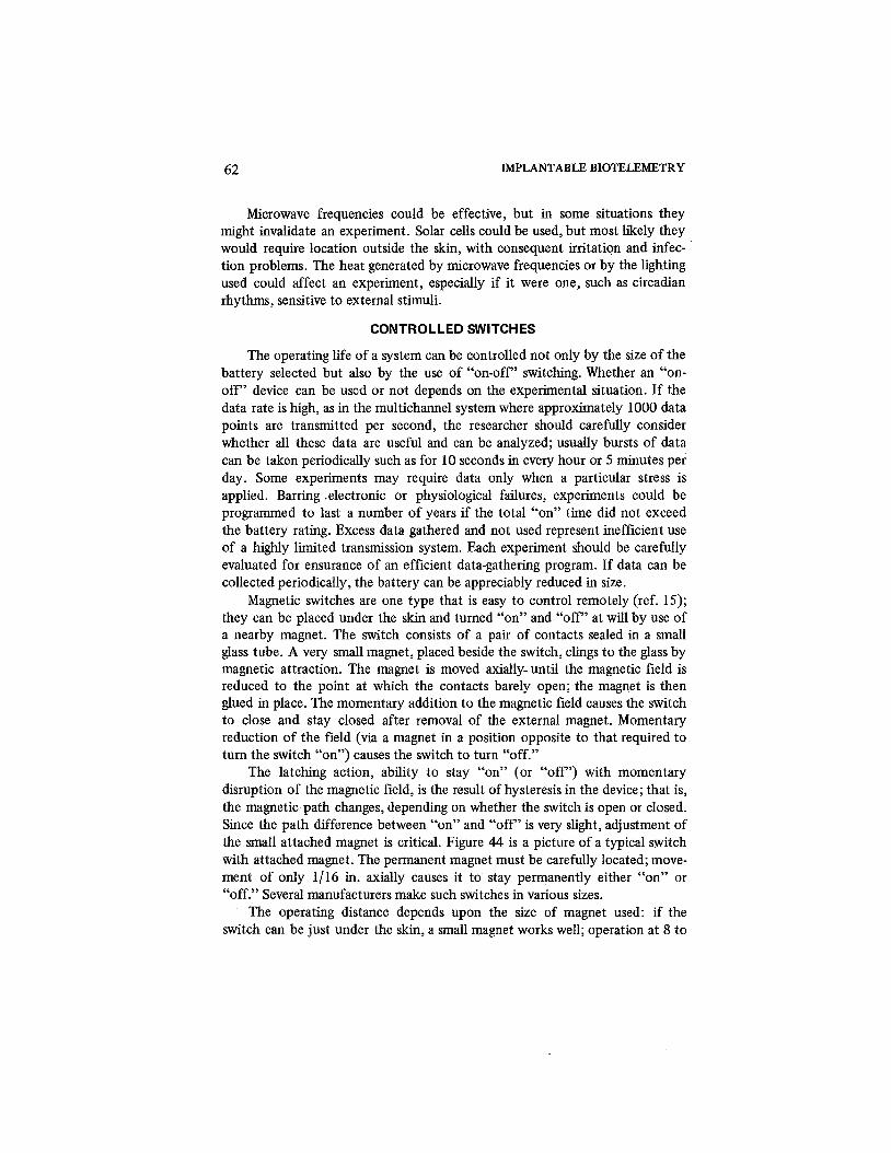
62 IMPLANTABLE BIOTELEMETRY
Microwave frequencies could be effective, but in some situations they might invalidate an experiment. Solar cells could be used, but most likely they would require location outside the skin, with consequent irritation and infec- tion problems. The heat generated by microwave frequencies or by the lighting used could affect an experiment, especially if it were one, such as circadian rhythms, sensitive to external stimuli.
CONTROLLED SWITCHES
The operating life of a system can be controlled not only by the size of the battery selected but also by the use of "on-off' switching. Whether an "on- off ' device can be used or not depends on the experimental situation. If the data rate is high, as in the multichannel system where approximately 1000 data points are transmitted per second, the researcher should carefully consider whether all these data are useful and can be analyzed; usually bursts of data can be taken periodically such as for 10 seconds in every hour or 5 minutes per day. Some experiments may require data only when a particular stress is applied. Barring .electronic or physiological failures, experiments could be programmed to last a number of years if the total "on" time did not exceed the battery rating. Excess data gathered and not used represent inefficient use of a highly limited transmission system. Each experiment should be carefully evaluated for ensurance of an efficient data-gathering program. If data can be collected periodically, the battery can be appreciably reduced in size.
Magnetic switches are one type that is easy to control remotely (ref. 15); they can be placed under the skin and turned "on" and "off' at will by use of a nearby magnet. The switch consists of a pair of contacts sealed in a small glass tube. A very small magnet, placed beside the switch, clings to the glass by magnetic attraction. The magnet is moved axially-until the magnetic field is reduced to the point at which the contacts barely open; the magnet is then glued in place. The momentary addition to the magnetic field causes the switch to close and stay closed after removal of the external magnet. Momentary reduction of the field (via a magnet in a position opposite to that required to turn the switch "on") causes the switch to turn "off."
The latching action, ability to stay "on" (or "off') with momentary disruption of the magnetic field, is the result of hysteresis in the device; that is, the magnetic path changes, depending on whether the switch is open or closed. Since the path difference between "on" and "off' is very slight, adjustment of the small attached magnet is critical. Figure 44 is a picture of a typical switch with attached magnet. The permanent magnet must be carefully located; move- ment of only 1/16 in. axially causes it to stay permanently either "on" or "off." Several manufacturers make such switches in various sizes.
The operating distance depends upon the size of magnet used: if the switch can be just under the skin, a small magnet works well; operation at 8 to
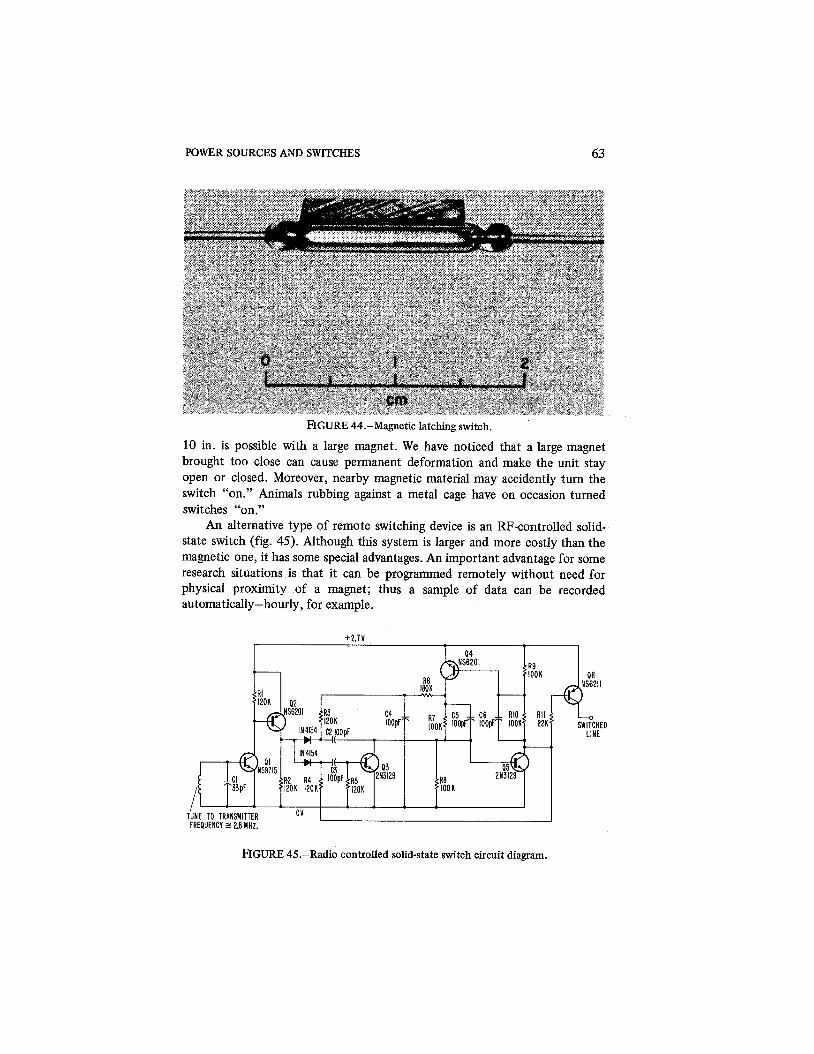
POWER SOURCES AND SWITCHES 63
FIGURE 44.-Magnetic latching switch.
10 in. is possible with a large magnet. We have noticed that a large magnet brought too close can cause permanent deformation and make the unit stay open or closed. Moreover, nearby magnetic material may accidently turn the switch "on." Animals rubbing against a metal cage have on occasion turned switches "on."
An alternative type of remote switching device is an RF-controlled solid- state switch (fig. 45). Although this system is larger and more costly than the magnetic one, it has some special advantages. An important advantage for some research situations is that it can be programmed remotely without need for physical proximity of a magnet; thus a sample of data can be recorded automatically-hourly, for example.
R9
FREQUENCY E 2.8 MHz.
FIGURE 45.-Radio controlled solid-state switch circuit diagram.
64 IMPLANTABLE BIOTELEMETRY
The circuit operates as follows: A short burst of 2.8 MHz, generated in a 1-ftdiameter loop of wire, is picked up by an inductive coil; the inductor is tuned to resonance at 2.8 MHz with capacitor C1. The signal is rectified with Q1 and amplified with Q2 to form a trigger pulse for the solid-state switch. Transistor Q3 and the associated diodes, resistors, and capacitors form a steer- ing network to steer the pulse for bistable operation of Q4 and Q5. The bistable circuit Q4 and Q5 is stable in either the "on" or "off' state. When QS is "on," the solid-state switch Q6 is turned "off' via R11. Transistor Q6 is epitaxial and operated in a saturated condition to provide a low voltage drop; the voltage drop across it is approximately 40 mV with a load current of 2 mA. The 2.72-V power supply and the 2 mA are adequate to meet the power-supply requirements of the multichannel transmitter. (The circuit could be operated on 1.32V with slight modifications.) Each time a pulse of 2.8-MHz energy is received, the switch changes state from "on" to "off' or vice versa; it is then latched in that state until a new pulse is received.
The operating range of the system is very limited. The transmitting antenna is a small fraction of a wavelength, so that as an rf radiator it is very ineffective. The system can be considered to be a transformer coupled by an inductive field. The sensitivity drops off as the third power of distance, so that for increase in range a sizable increase in pulse power is required. The receiving circuit also is quite insensitive, since a signal of at least 0.5 V is required for reaching the rectification level of the base-to-emitter junction of the silicon transistor Q1. The sensitivity could be improved by elimination of the 0.5-V offset voltage, but this would require additional idling current. The circuit at present draws no current in the "off' condition, since all transistors are biased "off." The lack of sensitivity offers one advantage in that the system is not likely to be triggered "on" by extraneous noise signals.
The present range is satisfactory for operation in a closely confined cage, but the transmitting and receiving coils must be properly aligned for full effectiveness. If the orientation is unknown, as it would be for automatic use, the "turn-on" (or "off') operation is uncertain; this difficulty can be overcome by sequential pulsing of a number of coils located at different positions and orientations; the pulsing is stopped as soon as the telemetry system starts to broadcast. In other words the physiological telemetry system can be used as a transponder to determine the "on-off' condition.
For a range of many miles, a much more efficient receiving and trans- mitting system must be used. Model-airplane control systems operating in the citizens' band provide this sort of range, but their sensitivity makes them subject to noise interference, and their consumption of power while idling is high; a typical current drain is 6 mA at 3 V. Such a switch would conserve no power in the low-power-level systems described, but might be useful under special circumstances. Redesign might reduce the current drain.
CHAPTER 9
Radio Transmission from Inside the Body
The use of radiotelemetry from inside the body presents unique problems in addition to those inherent in any rf link. The choice of receiver, modula- tion scheme, transmitting and receiving antennas, and operating frequency must all be considered in the optimization of a system. Special designs may be required for optimum results in different research situations: for instance, monitoring a small animal in a cage is quite different from monitoring a large animal free to move over a wide area, and one system cannot provide optimum results for both. The following discussion is intended to guide the selection of the best system for a particular research problem. Caceres' Biomedical Telem- etry (ref. 16) is a helpful source of information (especially ch. 9) that discusses many aspects of telemetry from within animals.
OPERATING FREQUENCY
All the circuits described here operate in the FM band of 88 to 108 MHz. Many considerations have dictated the use of this band. Inexpensive receivers are readily available and this band has been approved by the FCC for low- power biomedical transmitters. The high frequency is advantageous in that a small antenna transmits effectively. Most important, operation in this band has met research needs satisfactorily.
Early workers in this field used a low-radio frequency, typically 300 to 1500 IrHz, for a number of reasons. One reason was that the early transistors were not capable of operation at high frequencies. Since 1960, transistors for operation at 100 MHz have been available, so the choice of frequency is no longer limited by this consideration. Another consideration was that the early investigators reasoned that the high frequencies would be greatly attenuated by the "lossy" dielectric of the body and that the signals would be too weak for proper reception. This assumption turned out to be incorrect; implanted systems work very well in the region of 100 MHz (ref. 17).
Although the body is a lossy medium when tested for t~ansmission, place- ment of a self-contained transmitter totally within the tissue represents a some- what different situation. The tissue absorbs energy, but it also appears to compensate for this loss by reradiation of energy and effective increase in the size of the transmitting antenna. At low frequencies a small antenna, required

66 IMPLANTABLE BIOTELEMETRY
for use in small animals, has very poor radiation efficiency, but at higher frequencies the efficiency is greatly improved. The frequency cannot be in- creased indefinitely since it is difficult to build low-power oscillators at the higher frequencies. Using the transistors shown, the transmitters that are described work well at 100 MHz. The antenna is small and provides satisfactory range, and inexpensive receivers are available.
The effect of body tissue on transmitters operating at different frequencies should be investigated; satisfactory operation in the present bands, and lack of time, have delayed this type of exhaustive test. Windows and absorption bands will no doubt be noted, but unless they are very prominent they will not justify a change in frequency. The availability of receivers and suitable oscil- lators, antennas, etc., is a principal consideration in selection of a frequency if one assumes that no radical changes in transmission due to body tissue occur. By tests, others have attempted to establish the effect of body tissue (refs. 18 and 19); antenna-pattern and field-strength tests were made with transmitters located both in animals and in beakers of aqueous saline. Over a frequency range of 40 to 198 MHz the change between free air and a beaker of saline solution showed only a minor variation of -+ 5 db.
The rf oscillators used so far work best at up to about 120 MHz, so higher frequencies have not been tried. Experiments by others have been suc- cessful at from 200 to 250 MHz (ref. 20). All the modulation and coding techniques in circuits described work satisfactorily at a higher carrier frequency if a suitable rf stage is used. The tank circuits on the rf oscillators described can also be tuned to frequencies as low as 10 MHz if necessary; unless there were other important considerations, a lower frequency would not be used since the antenna efficiency is lowered and consequently the range is reduced. The frequency just below 88 MHz may be very useful in avoiding interference from hifi stations. Frequencies in the range between 300 and 1500 kHz are ruled out by the short-duration pulsed-modulation schemes that are used.
The rf circuits described oscillate reliably at 100 MHz when operated at a current level of 0.5 mA; receivers are readily available. Reception over several hundred feet is possible with standard sensitive receivers. The 100-MHz region appears to be well suited to biomedical applications.
ANTENNAS
The antennas used for receiving and transmitting vary considerably, depending on the type of experiments being performed. The size of the animal often limits the size of the radiating antenna, but the receiving antenna usually is not restricted in size and can be tailored for maximum sensitivity. The configuration of the antenna depends on the frequency of operation.
The first transmitters described (fig. 4) used an air-core coil of three turns of about 314-in. diameter. Transmission was in the 88-to-108-MHz band. With a

RADIO TRANSMISSION FROM INSIDE THE BODY 67
continuous carrier and 0.8 mA of current from a 1.35-V power source (1.08-mW oscillator power), operation at 100 to 200 ft was possible. The receiving antenna was a dipole cut to 1/2X and a high-quality hifi receiver (2-pV threshold level) was used. These conditions apply to an unobstmcted- line-of-sight test; steel cabinets, concrete buildings, etc., cause reflections, and these problems become more severe as the frequency increases. At 100 MHz the problem exists; it would be worse at 200 to 250 MHz, while at 10 to 30 MHz it diminishes. The relative orientation of the transmitting and receiving antennas also affects the range; the effect of orientation, reflection, etc., requires that each research situation be individually evaluated for determi- nation of a satisfactory operating range.
To monitor an animal in all orientations and positions, one should not work at the fringe of sensitivity as represented by the range of 100 to 200 ft. If the transmitter and receiver are located in a 15- X 20-ft room, for instance, reliable signals can be expected; the null condition will be very sharp and not significant, and the signal will be strong enough to overcome all except the strongest local stations. Careful selection of frequencies will eliminate signals from these stations. In summary, a transmitter of this type can be expected to give good results in a room-sized environment, but is usable at a greater range only under controlled conditions.
POWDERED-IRON ANTENNA CORES Use of powdered-iron-core antennas is an important development toward
small, compact transmitters that can be properly sealed for implantation. The round air-core antenna (fig. 4) did not lend itself to the hermetic sealing required for reliable operation in the body (ch. 11). The metal case that is most easily adapted to the variety of hermetic enclosures required interferes with the operation of the rf oscillator. Winding of the transmitting coil around a small powdered-iron core yields a compact antenna free of waste air space and capable of placement in close proximity to a metal case without disturbance of the operation of the rf oscillator.
Figure 46 shows typical powdered-iron pieces that have been used. The powdered iron is commercially available for use as a toroid; here it is used as a hollow slug so that the rf field has the normal dipole pattern but is highly concentrated in the vicinity of the transmitter. Since there is a large air gap, the Q of the ferrite material at the 100-MHz operating frequency is not critical. A material suggested for use as a toroid up to 20 MHz worked well in this application. Some of the higher-frequency materials have a lower magnetic permeability but result in less loss of power in the coil (higher Q). Since most of the r f -~ t a~e -~ower must be dissipated in the circuitry because of inefficient radiation, the use of a high-Q material is not important. If the range is maxi- mized by improvement of the rf efficiency, the Q of the ferrite dore is important.

IMPLANTABLE BIOTELEMETRY
,OPENING FOR BATTERY
/RF COIL TYPICAL CORES USED
TYPICALLY 3 TURNS NO. 28 WlRE TO OBTAIN 100 MHz. WlRE SIZE SPACING AND NUMBER OF TURNS USED TO ADJUST TO THE EXACT DESIRED FREQUENCY
FIGURE 46.-Powdered iron core antenna configuration.
The powdered-iron core, as applied to the short-range application (< 200 ft), has proved equally as effective as the 314-in.-d:am air-core antenna (fig. 4); signal-strength tests show insignificant differences. For the very small tempera- ture transmitter (fig. 19) a 318-in.-dim by 118-in.-thick core has been used. Since the inner diameter is only 0.210 in., it must be enlarged to accept the 0.310-in. battery (RM312 or S13E) that is normally used. Because these cores are very hard and abrasive after molding, special equipment is needed to grind them. Powdered iron is very brittle and, since the wall thickness is only 0.035 in. after grinding, the units are very fragile and easily broken. For the larger transmitters such as the pressure and multichannel systems a larger core such as a 112-in. (outer diameter) X 3116-in. unit with a 0.3-in. inner diameter, is used for ruggedness; the batteries are usually located remotely so that no grinding is necessary. A medium-sized unit (0.437-in. outer diameter, with a 0.25 -in. hole and 118-in. thick) is frequently used with a battery located in the center (fig. 14). Although this unit also must be ground out, it provides a heavier rim that is more rugged. Unfortunately no off-the-shelf cores are available having ideal inner and outer diameters to fit the batteries while retaining small size overall.
NONRADIATING TANK CIRCUITS
All the circuits, both continuous and pulsed, so far described have used a tank circuit having an inductor that serves a dual purpose: as both the induc- tive element in the tank circuit and the RF radiator. Most of the circuits have

RADIO TRANSMISSION FROM INSIDE THE BODY 69
used the ferrite core to maintain small size and provide satisfactory radiation. Recently a new, modified circuit arrangement has been used in which the tank-circuit inductance and the radiator are separate and distinct elements (fig. 47). It should be noted that this is merely a modification of the rf stage; where desirable it can be applied to all the pulsed or FM circuits already described.
The tank-circuit inductor is now a miniature toroid with a spirally wound coil in the conventional manner (fig. 47) so that very little power is radiated. For good rf radiation a short stub is attached to the inductor. A tapped-down point is used on the inductor to uncouple the antenna from the tank circuit and provide greater frequency stability in the rf oscillator. The number of turns on the inductor depends on the operating frequency desired. The 11 turns, with a three-turn tap for the antenna, give approximately 100 MHZ, and, by addition or subtraction of turns, change in size of wire, etc., a precise frequency can be obtained.
There are both advantages and disadvantages to this technique, and the best type of antenna depends upon the research situation. The loop antenna is very compact and no wires need protrude from the transmitter in the case of a temperature unit; but the very small loop antenna is not an efficient radiator and is therefore detrimental if maximum range is essential. The loop antenna has been most used because of its convenience and because maximum range is
RADIATING STUB
TOTAL OF II TURNS NO. 3 5 WIRE CORE 0.125in. O.D. 0.062in. I.D.
0.05 in. THICK HIGH FREQUENCY POWDERED
IRON CORE MATERIAL
FIGURE 47.-Alternative antenna arrangement.
70 IMPLANTABLE BIOTELEMETRY
not needed with caged animals. With a stub antenna the length of the wire can be adjusted to give the best radiation. Tests have been run with stranded stainless-steel wires, from 4 to 6 in. long. inserted in Silastic tubing for an- tennas, and the signal strength is somewhat stronger than with the loop type. The size of the animal limited the practical length to from 4 to 6 in. In free air the ideal length would be 1/4h or approximately 30 in. at 100 MHz, but, because of the lossy medium of the body, empirical tests with each type of animal and antenna arrangement would be required for optimization of the radiation for an implanted system.
The loop antenna is quite susceptible to frequency changes because of the distributed capacity effects on the exposed coil; with a loop unit the frequency may change by as much as from 1 to 2 MHz between free air and implantation. If a particular frequency is decided upon to avoid local stations, this frequency change must be compensated for in a free-air adjustment. Once the device is implanted, the frequency is quite stable. Greater difficulty is experienced with external units placed on the skin. Variations in distributed capacity cause frequency changes, although small variations can be taken care of by use of AFC on the receiver. The stub antenna, with the decoupling effect of tapping down on the inductor, provides much greater frequency stability and is especially useful with externally mounted antennas.
In conjunction with the small tapped inductor a large loop, approximately 3 in. in diameter, can be used in place of the stub; it greatly improves the radiation because of the larger coil diameter, but retains the freedom from distributed capacity changes altering the carrier frequency (due to decoupling of the antenna and tank-circuit inductor). The 22-pF capacitor is chosen to provide series resonance with the stub or large-loop antenna used. Except for optimum radiation, critical tuning is not required, and it is better to make the capacitor larger rather than smaller than the critical tuning value.
The decision to use a loop-type antenna, or a decoupled stub or a decoupled loop depends on the package requirements and the particular research situation requiring the device.
METHODS OF INCREASING RANGE
Primarily we have used radiotelemetry to obtain data from unrestrained animals; long range has not been required since the animals were either caged or in a room. For longer range the systems described could be modified. The transmitter's power, transmitter's antenna, carrier frequency, receiver, and receiving antenna would all need careful evaluation for optimization of range.
A high-quality telemetry receiver should be used, allowing the selection of any desirable frequency between 30 and 250 MHz. The choice is limited by FCC regulations as well as the need for a quiet section of this rf band. A change in the carrier frequency requires no change in the circuits described

RADIO TRANSMISSION FROM INSIDE THE BODY 7 1
except for minor changes in the rf stage to produce the desired oscillation frequency. Between 20 and 120 MHz only a change in the tank circuit is required. Above 120 MHz a higher frequency transistor than the 2N709 should be used. In other words, a change in the rf carrier alters none of the charac- teristics of the systems that have been described.
The design of the radiating antenna is most important for greater range. The 314-in. air-core coil, or its equivalent ferrite one, is improperly matched for maximum radiation, but is satisfactory for short-range applications where minimum size is critical. For larger animals a decoupled stub antenna or a larger loop can be used for more effective radiation.
A quarter-wave stub in free air is an effective antenna, but its operation within tissue presents special problems. Some workers (ref. 17) have concluded that the tissue attenuation is not serious when the magnetic field is optimized, as with a radiating coil; but, if the electric field is optimized as with a quarter- wave stub, the situation is altered. The arrangement for each research situation must be evaluated individually.
For maximum range a backpack transceiver also may be considered; it would consist of a receiver to pick up the telemetry signal (from inside the animal at short range) to be retransmitted by a high-powered transmitter at a second frequency. The effective quarter-wave stub has been used successfully (refs. 18 and 19) with backpack systems; this arrangement allows for periodic replacement of the heavy-drain batteries.
Regulations by the FCC permit operation of low-powered biomedical transmitters in the FM band provided that the range is limited to less than a few hundred feet and that it does not interfere with standard equipment. Any means used to increase the range, whether by more-efficient radiating antennas or greater transmitter power, would require the FCC's approval.
CONFIGURATIONS USED
The circuits that have been described fall into two fairly distinct categories as far as their radio-transmission characteristics are concerned. First there are the very-short-range units having pulsed carriers and a maximum range of 6 to 10 ft. They are very susceptible to external noises such as stepping switches, the ignition of automobiles, etc., and require rf shielding for the best results. In the second category are the short-range units that have a continuous carrier and a range of 100 to 200 ft. These signals are strong enough to overcome all but strong local stations; results are very reliable in a room-sized environment, and shielding is not required.
CONTINUOUS-CARRIER SYSTEMS
The pressure and multichannel systems have been used primarily with a continuous carrier, since the transducer power precludes operation at the

72 IMPLANTABLE BIOTELEMETRY
extremely low microwatt levels of the pulsed temperature and EKG units. Magnetic switches are used to conserve power and provide long-term operation. They are used in the large animals, such as dogs, where free motion within the confines of a room is desirable. The FM band has been used but with the frequency adjusted for avoidance of strong stations; the band from 88 to 92 MHz usually works best. With a telemetry receiver or by slight modification of a hifi receiver, the frequencies between 86 and 88 MHz are useful. The receiv- ing antenna is a standard folded dipole of "rabbit ears" as used with hifi receivers. Another type of antenna that can be used if the research situation allows is a 6-to-8-in. loop at the end of a coaxial cable. It must be placed close to the animal but is convenient if the animal is restrained or on a leash. The loop reduces the signal strength of interfering stations and noise sources and strengthens the pickup from the telemetry system.
EXPERIMENTS WITH CAGED ANIMALS
The other category of experiments concerns small animals, such as rats, monkeys, and chickens, in cages. The pulsed temperature and EKG trans- mitters have been used primarily, so that long-term continuous monitoring has been possible as needed in circadian-rhythm experiments. Proper shielding, to eliminate rf interference, is essential for clean, noise-free records. The cage is usually made of plastic material so that the antenna can be mounted on it; the cage is then surrounded with a cage of copper screening for rf shielding. It is very important that the antenna be located at least 2 in. away from any metal structure or shielding for avoidance of severe attenuation of the signal; a spac- ing of 5 to 6 in. is preferable. A metal cage can be used if provision is made to locate the antenna inside but at an adequate distance from the metal cage; a piece of twin lead, cut as a folded dipole and wrapped around the plastic cage, is suitable. Around a very small cage a piece of wire can be wrapped.
The use of individually shielded cages is desirable so that transmitters in different animals do not interfere with each other. The pulsed mode of opera- tion creates many sidebands, so that one must allow generous spacing between transmitter frequencies. Individual shielding allows the use of the same fre- quency in many different animils. If both temperature and EKG measurements are made in the same animal, the frequencies should be spaced by 5 MHz or more. This type of spacing will not allow for the operation of very many units in the FM band without individual shielding.
The close spacing of the transmitting and receiving antennas normally provides a strong signal, but not always. At any position in the cage a particular orientation of the transmitting antenna, relative to the receiving one, results in a null. With a high-sensitivity receiver this null can be reduced to only a few degees of angle. For a certain percentage of time an animal may be so posi- timed and oriented that a null may result; the probability of this is reduced as

RADIO TRANSMISSION FROM INSIDE THE BODY 73
the sensitivity is increased. Using hifi receivers we have found that the per- centage of time with signal dropouts due to nulls is very small and is easily identified on the records (fig. 48). If the experiment cannot tolerate any possibility of dropouts, three orthogonal antennas must be used, sending to three receivers; the outputs can be combined so that a strong pulse is always available for the demodulator. As an alternative, the three antennas can be connected through three commercially available FM-TV-type preamplifiers for use in fringe-area reception; they increase sensitivity and are inexpensive. A switching arrangement is used to select one of the antennas that has a strong signal; if the signal fades due to nulling, another (differently oriented) antenna is coupled to the receiver. This then requires only one receiver for data com- pletely free of dropouts.
RECEIVERS
The receiver to be used depends upon the frequency selected. For the FM band, commercial hifi receivers have proved very satisfactory. For a typical receiver a minimum usable signal level of about 2 pV will be specified. The 100-to-200-ft range of the continuous transmitter is based on this type of receiver. The small, inexpensive portable receivers are not only less sensitive but also lack selectivity. The hifi receivers work very well with the pulsed transmitters, but the inexpensive portable units are marginal in sensitivity. The FM receiver may be converted to AM operation for use with the pulsed re- ceivers, merely by rectification of the signal at the end of the IF strip with a diode (fig. 49).
The more expensive telemetry receivers work extremely well in the systems described, usually with little difference in sensitivity but normally with
1200 1000 0 8 0 0 0 6 0 0 0 4 0 0 0 2 0 0 0000 NOON TIME MIDNIGHT
FIGURE 48.-Analog temperature recording showing the effect of signal dropout and interference due to the lack of adequate RF shielding.

74 IMPLANTABLE BIOTELEMETRY
STANDARD FM I RECTIFIER I SATURATED PULSE I RECEIVER I I AMPLIFIER I
I I ! I
SHORT LEAD I
LAST IF STAGE i I N A RECEIVER
TO DEMODULATOR
NOTES: SATURATED OUTPUT PULSE FOR 0.15V INPUT OR GREATER
FIGURE 49.-Receiver modification for use with transmitters operating with pulse mode RF carriers.
better selectivity than a hifi receiver. The important feature is that they are usually tunable from 30 to 250 MHz, giving greater freedom in selection of a frequency that is free of interference. Other common features are the abilities to operate on AM or FM, change bandwidth, etc.
The telemetry receiver has proved desirable for use with the multichannel system, but is by no means essential. The signal wave form is critical in the multichannel system, and a telemetry receiver can be adjusted to give a better wave form. The fact that four or more channels of information are recovered, coupled with the cost of the transmitter and transducers, makes the cost of the receiver less significant. The single-channel transmitters are used in quantity, so that receiver cost is important. A typical setup may have two transmitters per animal and eight animals. For use with the single-channel system, the hifi receiver, modified for AM operation, has proved very reliable and satisfactory.
MODULATION
The type of modulation used has a great deal to do with the operating range and the selection of frequency. As has been noted, all the systems described use some form of subcarrier to retain accuracy and reliable rf-transmission of data. Systems have been described in the literature that use FM without a subcarrier; this practice limits accuracy in the case of a critical measurement such as temperature and can cause baseline shifts in the case of EKG's. Body motions alter the rf slightly and consequently affect the data. The pulsed mode of operation was selected to conserve power, and then has been used with continuous carriers so that one design may serve both applica- tions.
Radio-frequency transmission is limited in range by a number of factors, one being bandwidth; because of unwanted noise, the wider the bandwidth the

RADIO TRANSMISSION FROM INSIDE THE BODY 75
shorter the operating range. In the pulsed mode the range is limited because of the wide bandwidth required; the 10-to-40-psec pulses create sidebands that partly determine the required bandwidth. A worse problem is that the simple rf oscillator, used in the transmitter, is not frequency-stable while the pulse is "on." Very small voltage changes at the base of the rf transistor cause large changes in frequency. This effect, of course, is used in the continuous con- figuration for frequency modulation, but is undesirable in the pulsed mode. One millivolt at the base of the rf transistor causes a change in frequency as great as 100 kHz in the circuits shown.
The bandwidth has been limited in the revised circuits of Chapter 4 by two means: the pulse width has been increased to about 35 psec at a minor expense in power but with significant reduction in the sidebands; and addition of an emitter-follower, between the SCO and the rf stage, has stabilized the voltage at the transistor base. These modifications have reduced the bandwidth of the transmitted signal to approximately 50 kHz. A standard FM receiver, with a 200-kHz IF bandwidth, properly receives the signal. Before the modification the transmitted signal had a bandwidth between 300 and 500 kHz, and use of a standard receiver resulted in the loss of many sidebands. Although the system worked satisfactorily, the signal strength was lowered by the loss of energy in the sidebands.
This modification to reduce the sidebands suggests that further narrowing would increase the range even further. This has been tried in one experimental model in which a crystal was used to prevent frequency modulation of the RF. Figure 50 is a circuit diagram of a temperature transmitter using a crystal- controlled oscillator. The same type of Colpitts oscillator is used, but with the addition of a crystal in the feedback path. In this case, one must tune carefully the tank circuit to the crystal frequency; otherwise the circuit does not oscillate. The separate tank circuit and antenna are particularly useful in this case. The timing capacitor in the SCO has been increased from 5000 to 50,000 pF. By this means, the interval between pulses has been increased by roughly a factor of 10, and the pulse duration has been increased proportionally. Since the duty cycle (ratio of "on" to "off" time) has not been changed, the power consumption is the same. The longer pulses are useful for two reasons: the sidebands are further reduced to allow narrow-band operation; and, because of the high Q in a crystal, it is difficult to turn it "on" and "off' rapidly. The longer pulse, then, facilitates more reliable pulsed operation of the crystal.
Trials of a crystal operating at 88 MHz, with a telemetry receiver set at 30-kHz bandwidth, revealed an operating range of 200 ft. The range is in- creased at sacrifice in size because of the crystal and larger capacitor, and also in increased cost and complexity. Use of a telemetry receiver for narrow- bandwidth operation is almost essential. The major sidebands of a pulse are contained within a bandwidth of l /h; so for the 300-psec pulse used, a band of

76 IMPLANTABLE BIOTELEMETRY
1.35 SOLID STATE SWITCH I SUBCARRIER OSCILLATOR I RF OSCILLATOR
NOTES: I. THERMISTOR EXTERNAL TO INTEGRATED CIRCUIT 2.C4 - CORNING ELECTRONICS CYK 01 BU 472K 3. INDUCTOR EXTERNAL TO INTEGRATED CIRCUIT 4.COLLECTOR LEAD OF 0 4 TO BE BROUGHT OUT OF INTEGRATED CIRCUIT 5.X CRYSTAL MCCOY M M - 8 8 MHz
FIGURE 50.-Temperature transmitter modified for use with a crystal controlled RF stage.
3 kHz contains most of the energy. This means that a bandwidth of 3 kHz on the receiver would further increase the range.
The modification shows how a few simple circuit changes can adjust the performance to meet special experimental requirements. The size, cost, and complexity are increased, but the basic system (i.e., the pulse-modulation scheme using the ratio between two successive pulse intervals for accuracy) remains unchanged. The use of even longer pulses is possible, the only lirnita- tion being the information bandwidth. Since temperature is a very slowly changing parameter, a bandwidth of only a few Hertz is needed, but in the case of EKG's, for instance, 150 Hz would normally be required, and even more for EMG's. These considerations limit the extent to which the pulse width and interval can be adjusted.

CHAPTER 10
Construction Techniques The construction techniques used are extremely important in achieving the
small size necessary for implanted telemetry. Both soldering together of discrete parts and microelectronic fabrication have been successful. Several factors such as cost, production quantity, and available facilities must be con- sidered in determining the most suitable fabrication technique.
All circuits described have been designed to allow the use of discrete components, as well as fabrication by the hybrid integrated-circuit technique; the advantage is low initial cost and flexibility in easy adjustment of the designs for special requirements. The cost advantage of discrete components is diminishing as integrated circuits become more available and drastically reduced in price. This is especially true when the cost of interconnecting many miniature parts is considered. The major drawback to the use of integrated circuits is that they consume too much power for the applications at hand; this may be reduced by future developments in integrated circuits.
DISCRETE COMPONENTS
The discrete-parts approach offers the greatest flexibility and reasonably small size, with careful selection of parts and construction. Of course the circuits must be designed so that all necessary components are obtainable in miniature configurations; a design requiring a 50-/.IF capacitor or a large inductor would not be suitable for a miniature device. Figure 51 shows a typical set of components for a pressure-cell telemetry system (fig. 21) includ- ing the plastic former. Note the uniform size and configuration of the parts; this is a great aid in achievement of small size with discrete parts.
Figure 14 shows an assembled EKG transmitter, using discrete parts, that can be compared with an earlier model (fig. 4) also built from discrete parts. The circular configuration has been changed to rectangular; in addition to reasons of sealing (which will be explained in ch. 1 l), the rectangular shape is more flexible for size changes to meet the needs of individual circuits. It should be noted that the plastic wafer is not an essential part of the design, but merely a convenient construction jig and rugged frame for the finished device. Other construction techniques can be used successfully with the circuits described; for instance, the standard cordwood techniques using punched Mylar sheets achieve approximately the same packing density. A potting material poured around the parts achieves the same effect without need for molding of special wafers. One wafer has space for all components in the single-channel designs,

78 IMPLANTABLE BIOTELEMETRY
FIGURE 51.-Unassembled parts for a pressure cell transmitter.
while several wafers are used with the multichannel designs. Figure 52 shows the assembled electronics for a multichannel system before sealing in a metal can.
The early circuits used transistors in a TO-51-type case (fig. 4) that was both awkward to handle and required specially drilled holes. All subsequent circuits have been designed with transistors mounted on ceramic microchips, such as 2N3129 and NS6065. This packing consists of a transistor chip attached to a 0.05 X 0.05-in. ceramic substrate sealed with epoxy and having 0.005-in. external leads. This package is compatible with the resistors and capacitors and they all fit in one standard 0.073-in. hole. Although most types of transistors can be packaged in this configuration, the custom work entailed is very expensive. Both the 2N3129 and the NS6065 are examples of standard types of transistors. All the circuits have been designed with similar modulator techniques, power supplies, rf stages, etc., so that the variety of parts required is reduced. By careful design, a few types of transistors have sufficed to meet all the circuit needs and simplify the procurement problem.
All capacitors and resistors are selected to fit the 0.073-in. hole and are less than 0.150 in. long. Since the total power consumption is only a few
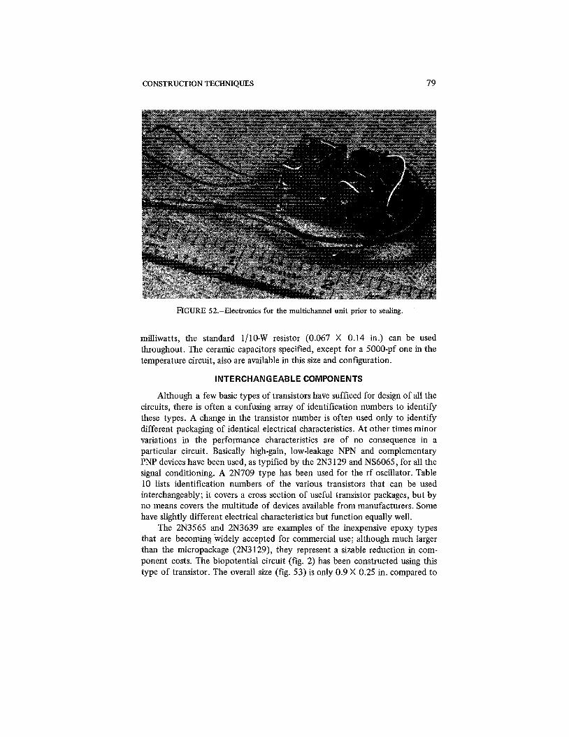
CONSTRUCTION TECHNIQUES 79
FIGURE 52.-Electronics for the multichannel unit prior to sealing.
milliwatts, the standard 1110-W resistor (0.067 X 0.14 in.) can be used throughout. The ceramic capacitors specified, except for a 5000-pf one in the temperature circuit, also are available in this size and configuration.
INTERCHANGEABLE COMPONENTS
Although a few basic types of transistors have sufficed for design of all the circuits, there is often a confusing array of identification numbers to identify these types. A change in the transistor number is often used only to identify different packaging of identical electrical characteristics. At other times minor variations in the performance characteristics are of no consequence in a particular circuit. Basically high-gain, low-leakage NPN and complementary PNP devices have been used, as typified by the 2N3 129 and NS6065, for all the signal conditioning. A 2N709 type has been used for the rf oscillator. Table 10 lists identification numbers of the various transistors that can be used interchangeably; it covers a cross section of useful transistor packages, but by no means covers the multitude of devices available from manufacturers. Some have slightly different electrical characteristics but function equally well.
The 2N3565 and 2N3639 are examples of the inexpensive epoxy types that are becoming widely accepted for commercial use; although much larger than the micropackage (2N3 129), they represent a sizable reduction in com- ponent costs. The biopotential circuit (fig. 2) has been constructed using this type of transistor. The overall size (fig. 53) is only 0.9 X 0.25 in. compared to

80 IMPLANTABLE BIOTELEMETRY
TABLE 10.- Transistor Interchangeability
Ceramic Commercial Case TO-18 microtransistor epoxy Vicro tab
-
Size, in. 3/16 diam X 0.05 X 0.5 X 0.215 diarn X 0.070 diam X 3/16 0.03 0.25 0.085
NPN 2N2484 2N3129 2N3565 D26E-1
PNP 2N3504 NS6065 2N3639 D30A-3
NPN , high frequency 2N709 NS9715 2N3563 D26G-1
0.75 X 0.18 in. (fig. 2). The greater space between parts makes the wiring easier, the cost of parts is lower, and the volume is only doubled.
Before assembling the components of a system into the final miniature configuration, one should check it on a breadboard (fig. 54). The parts are easily accessible when connected in this way and all the circuit wave forms can be checked easily. Faulty components can. be replaced and circuit adjustments made easily. The functioning of the breadboard and the final unit demonstrates that the parts layout is not critical in these circuits. The rf stage should be wired with short leads to prevent undesirable inductive and capacitive effects. Figure 55 is a breadboard of an eight-channel transmitter.
INTEGRATED CIRCUITS
As already indicated, the cost of integrated circuits has dropped drastically in recent years and this type of device offers advantages in size. The major limitation for implanted telemetry is the heavy power drain; typical circuits draw many milliamperes and are designed for use at from 3 to 6 V or higher. Low power consumption requires resistances of from 100 ki2 to many megohms, which are not feasible at present. Future developments may correct this situation. Field-effect transistors offer very low-power operation, but usually-require 6 to 10 V for proper operation; because of battery sizes this is not a satisfactory operating level. Some recent FET devices, designed for lower voltages, may be useful. This fact, coupled with the new integrated-circuit techniques with field-effect devices (large-scale integration, LSI), makes dramatic developments possible in the future.
The term "integrated circuits" has been used in connection with two quite different techniques: monolithic and hybrid. The monolithic integrated circuit describes a process whereby all components, resistors, capacitors, and tran- sistors, are diffused on a single monolithic substrate of silicon. The word

CONSTRUCTION TECHNIQUES 8 1
FIGURE 53.-Biopotential circuit (fig. 2). constructed using inexpensive commercial epoxy-type transistors.
"hybrid" implies a mixture, and this technique is a mixture of discrete- component and integrated-circuit methods. Each of several hybrid processes uses a different combination of techniques. Thick-film and thin-film are two commonly used types of hybrid.
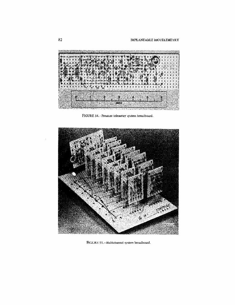
82 IMPLANTABLE BIOTELEMETRY
FIGURE 54.-Pressure telemetry system breadboard.
FIGURE 55.-Multichannel system breadboard.

CONSTRUCTION TECHNIQUES 83
Because the making of the necessary masks and the processing of mono- lithic integrated circuits are very expensive, custom-made circuits for specific requirements of biotelemetry are impractical. The standard off-the-shelf devices are inexpensive because of the economics of mass production, but to date they have not met the power and voltage requirements of this application. When suitable devices become available, the size and cost of the present systems will be further reduced. The present state of the art makes it impracti- cal to construct a circuit, such as the temperature transmitter (fig. 1 l), on one monolithic integrated circuit; the circuit is too complex for one chip without very poor production yields and resultant high cost. A number of chips, each having a specific purpose-rf oscillator, SCO, and solid-state switch-would be required. When devices suitable for use at very low levels of power and voltage are available the systems can be fabricated with monolithic integrated circuits.
The hybrid integrated-circuit technique has been successfully applied to construction of the circuits described. Figure 56 shows the two sides of a set of hybrid integrated circuits used to form the temperature-telemetry system of figure 17. A thick-film process has been used to deposit resistors and intercon- nections. Thin-film circuits (resistors and interconnections deposited on a substrate by condensation) also are used by industry as another form of hybrid circuits. Again the resistance values are limited, and the thick-film approach appears better suited to this application. The low cost of thick-film masks makes their use for special circuits practical and permits changes when required. Since discrete transistor chips, capacitors, and other components are individually attached and wired, the hybrid is really an extension of the discrete-component construction techniques for a greater degree of mini- aturization.
With the thick-film techniques the resistors and interconnections are silk- screened on a ceramic substrate. The screened conductive paths are similar to the interconnections provided by a printed circuit board. Considerable volume is saved by elimination of the discrete resistors. They are fired onto the substrate in the same manner as the interconnections, and the resistance value can be adjusted via the geometry and composition of the frit that is deposited. For precise resistance values the resistors can be trimmed with a miniature (dental tool) sandblaster (fig. 53). Transistor chips are attached to the substrate and wire-bonded for proper interconnection. Discrete capacitors have been used, but very small values can be screened on if the space allows.
When discrete parts are used, packaging of individual components con- sumes a great deal of the volume. Elimination of the individual packaging, and assembly of the basic parts before the final protective package is applied, as with integrated circuits, reduces the size significantly. The transistor itself is a particularly striking example of this factor. A standard TO-5 case has a 318-in. diameter and 114-in. thickness while a typical chip measures 0.025 X 0.025 X

84 IMPLANTABLE BIOTELEMETRY
FIGURE 56.-Thick film hybrid integrated circuit chips used in the temperature trans- mitter (fig. 19). Front and back views of the four chips used.
0.002 in.-a volume ratio of 25,000 to 1. The smaller ceramic packaging used with the discrete parts of figure 51 still represents a volume reduction of 100 to 1. The important point is that elimination of individual packaging of com- ponents significantly reduces volume.

CHAPTER 1 1
Sealing Techniques Proper sealing of electronic circuits to function inside the body is critical;
moisture is a primary cause of failure. The saline solution of the body is an extremely hostile environment for functioning circuitry. Failure because of the leakage of body fluids is one of the principal problems that have plagued developers of implanted systems; in contrast, backpack systems need only a modest degree of protection.
ADVANTAGES OF HERMETIC SEALING
Early tests of various encapsulants for sealing against moisture revealed no entirely satisfactory material. Some tests ran satisfactorily for many weeks before gradual drifts took place; in other tests, drifts started within days. The high-impedance circuitry required for long life accentuated the sealing problem. Complete reliability has been achieved only by use of hermetic seals, which have long been used on electronic components such as transistors and capacitors for protection from moisture. The total system becomes large when each component is individually sealed, but, as already pointed out, the saving in size is considerable when unprotected parts are assembled and sealed as a whole. Hermetic sealing allows one to make nondestructive tests such as helium or radioactivity leak tests to verify proper sealing, a point that is vital in the achievement of great reliability. In contrast, a plastic encapsulant, even if it were highly resistant to moisture, would be subject to unknown variables in fabrication. A slightly out-of-control procedure would not be detectable until an operational failure occurred.
Glass, metal, and ceramic are the three materials commonly used for hermetic sealing. They are completely impervious to moisture, and enclosures are usually rated in terms of the leakage rate of helium; a specification of 10'' cm3 lsec is common at I-atm differential pressure. Since water vapor has a large molecule, the leakage is even lower with moisture. This degree of sealing is adequate for many years of protection. The use of a metal container presents a unique problem for a radiotelemetry system since the metal prevents radiation. Glass or ceramic could be used without interfering with the radiation, but metals are usually easier to shape, less bulky, and more rugged.
COMPROMISE SEALING TECHNIQUE
By a compromise approach a metal can was used to seal the moisture- critical electronic components, while the radiating antenna was placed outside
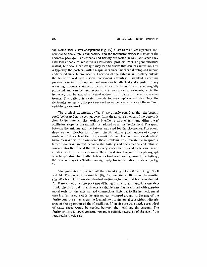
86 IMPLANTABLE BIOTELEMETRY
and sealed with a wax encapsulant (fig. 19). Glass-to-metal seals protect con- nections to the antenna and battery, and the thermistor sensor is located in the hermetic package. The antenna and battery are sealed in wax, and since they have low impedance, moisture is a less critical problem. Wax is a good moisture sealant, but poor shear strength may lead to cracks that can leak moisture. This is typically the problem with encapsulants since faults can develop and remain undetected until failure occurs. Location of the antenna and battery outside the hermetic seal offers some convenient advantages: standard electronic packages can be made up, and antennas can be attached and adjusted to any operating frequency desired; the expensive electronic circuitry is ruggedly protected and can be used repeatedly in successive experiments, while the frequency can be altered as desired without disturbance of the sensitive elec- tronics. The battery is located outside for easy replacement also. Once the electronics are sealed, the package need never be opened since all the required variables are external.
The original transmitters (fig. 4) were made round so that the battery could be located in the center, away from the air-core antenna. If the battery is close to the antenna, the result is inveffect a shorted turn, and either the rf oscillation stops or the radiation is reduced to an ineffective level. The space between the antenna and the battery was used for the electronics. This round shape was not flexible for different circuits with varying numbers of compo- nents and did not lend itself to hermetic sealing. The configuration shown in figure 57 was devised to overcome these problems. To eliminate the air space, a ferrite core was inserted between the battery and the antenna coil. This so concentrates the rf field that the closely spaced battery and metal case do not interfere with proper operation of the rf oscillator. Figure 58 is a photograph of a temperature transmitter before its final wax coating around the battery; the final unit with a Silastic coating, ready for implantation, is shown in fig. 59.
The packaging of the biopotential circuit (fig. 11) is shown in figures 60 and 61. The pressure transmitter (fig. 27) and the multichannel transmitter (fig. 41) both illustrate the standard sealing technique that has been devised. All these circuits require packages differing in size to accommodate the elec- tronic circuitry, but in each one a suitable case has been used with glass-to- metal seals for the external lead connections. External to the hermetic metal case is a ferrite core with the antenna coil wrapped around it. Because of the ferrite core the antenna can be located next to the metal case without disturb- ance of the operation of the rf oscillator. If an air core were used, a great deal of waste space would be needed between the metal and the antenna. The ferrite permits compact construction and is suitable regardless of the size of the required hermetic case.

SEALING TECHNIQUES 87
FIGURE 57.-Electronics and antenna arranged for effective RF propagation and con- venient sealing.
FIGURE 58.-A temperature transmitter ready for fin4 encapsulation.

88 IMPLANTABLE BIOTELEMETRY
FIGURE 59.-Encapsulated temperature transmitter.
ENCAPSULATION PROCEDURE
The various sealing materials that are applied to a typical pressure trans- mitter are shown in figure 62. A wax coating seals the antenna and battery against moisture. Except for the Silastic tubing used to connect the appendages (battery and pressure cell), the entire system is then coated with a thin layer (0.005 to 0.015 in.) of the liquid vinyl (Tygon). This coating adds to moisture protection and more importantly provides a tough, leather-like skin. The elasticity of the vinyl coating allows some deformation without cracking. The solvents in the liquid vinyl slightly dissolve the wax so that, when dry, the two are closely bonded.
Many plastics react with tissue and are toxic because of the solvents and plasticizers used. Extensive testing is required for determination of the magni- tude of this problem, since the effects often are long-term and statistical in
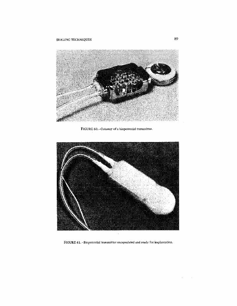
SEALING TECHNIQUES 89
FIGURE 60.-Cutaway of a biopotential transmitter.
FIGURE 61.-Biopotentid transmitter encapsulated and ready for implantation.

90 IMPLANTABLE BIOTELEMETRY
FIGURE 62.-Pictorial view of a system indicating the various materials and arrangements used to seal a pressure transmitter.
nature. The unknown effect of the liquid-vinyl coating on the body is pre- vented by a second coating of Silastic (RTV). Tests by other laboratories have shown Silastic to be one of the most inert and nonreactive plastics available, but it is not good moisture sealant. The hermetic case, wax, and vinyl coating provide moisture sealing, and the Silastic provides good compatibility with body tissue. Figure 63 is a cutaway view of a pressure transmitter; an encapsu- lated system, ready for implantation, is shown in figure 64.
The wires going to the appendages, battery, and transducer are housed inside medical-grade Silastic tubing. Small hookup wires coated with TFE- fluorocarbon are used inside. A 118-in. (outside) X 1116-in. (inside) tube easily handles the five wires required for the pressure cell. The commercial Silastic tubing, with the wires inside, is then fdled with liquid silastic and allowed to cure; the resultant solid Silastic cable has no voids in which moisture can collect.
PROBLEMS WITH EXTERNAL TRANSDUCERS
It will be noted that sealing a temperature transmitter with the transducer inside the hermetic case is a much easier problem than sealing a pressure or multichannel system where the transducers are external. The smooth, con- tinuous coating possible, without appendages to the transmitter, allows one to obtain a very reliable seal. The point where wires enter or leave a package is the weakest link in the sealing process. The motion of animals can cause stress at

SEALING TECHNIQUES 91
FIGURE 63.-Cutaway of a pressure telemetry system.
FIGURE 64.-Encapsulated pressure transmitter ready for implantation.
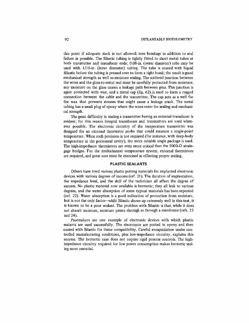
92 IMPLANTABLE BIOTELEMETRY
this point if adequate slack is not allowed; wire breakage in addition to seal failure is possible. The Silastic tubing is tightly fitted to short metal tubes at both transmitter and transducer ends; 0.08-in. (outer diameter) tube may be used with 1116-in. (inner diameter) tubing. The tube is coated with liquid Silastic before the tubing is pressed over to form a tight bond; the result isgood mechanical strength as well as moisture sealing. The soldered junction between the wires and the glass-to-metal seal must be carefully protected from moisture; any moisture on the glass causes a leakage path between pins. This junction is again protected with wax, and a metal cap (fig. 62)js used to form a rugged connection between the cable and the transmitter. The cap acts as a well for the wax that prevents stresses that might cause a leakage crack. The metal tubing has a small plug of epoxy where the wires enter for sealing and mechani- cal strength.
The great difficulty in sealing a transmitter having an external transducer is evident; for this reason integral transducers and transmitters are used when- ever possible. The electronic circuitry of the temperature transmitter was designed for an external thermistor probe that could measure a single-point temperature. When such precision is not required (for instance, with deep-body temperature in the peritoneal cavity), the more reliable single package is used. The high-impedance thermistors are even more critical than the 500042 strain- gage bridges. For the multichannel temperature system, external thermistors are required, and great care must be exercised in effecting proper sealing.
PLASTIC SEALANTS
Others have tried various plastic potting materials for implanted electronic devices with various degrees of success (ref. 21). The duration of implantation, the impedance level, and the skill of the technician all affect the degree of success. No plastic material now available is hermetic; they all leak to various degrees, and the water absorption of some typical materials has been reported (ref. 22). Water absorption is a good indication of protection from moisture, but is not the only factor-while Silastic shows up extremely well in this test, it is known to be a poor sealant. The problem with Silastic is that, while it does not absorb moisture, moisture passes through as through a membrane (refs. 23 and 24).
Pacemakers are one example of electronic devices with which plastic sealants are used successfully. The electronics are potted in epoxy and then coated with Silastic for tissue compatibility. Careful encapsulation under con- trolled manufacturing conditions, plus low-impedance circuitry, explains this success. The hermetic case does not require rigid process controls. The high- impedance circuitry required for low power consumption makes hermetic seal- ing more essential.

References
1. MACKAY, R S.; AND JACOBSON, B.: Endoradiosonde. Nature, vol. 179,1957, pp. 1239-1240.
2. GEDDES, L. A.: A Bibliography of Biological Telemetry. Am. J. Med. Electronics, vol. 1,Oct.-Dec. 1962, pp. 294,298.
3. DEBOO, G. H; AND FRYER, T. B.: Miniature Biopotential Telemetry System. Am. J. Med Electronics, vol. 4, no. 3, 1965, pp. 138-142.
4. FRYER, T. B.; DEBOO, G. J.; AND WINGET, C. M.: Miniature Long-Life Tempera- ture Telemetry System. J. Appl. Physiol., vol. 21, no. 1, Jan. 1966, pp. 295-298.
5. WINGET, C . M.; AVERKIN, E. G.; AND FRYER, T. B.: Quantitative Measurement by Telemetry of Ovulation and Oviposition in the Fowl. Am. J. Physiol., vol. 20, no. 9, Sept. 1965, pp. 853-858.
6. FRYER, T. B.: A Micropower Transmitter for Temperature Measurements. In Proc. 18th Annual Coderence on Engineering in Medicine and Biology, 1965, p. 104.
7. KONIGSBERG, E.: A Pressure Transducer for Chronic Introvascular Implantation. In. Proc. 4th National Biomedical Sciences Institute Symposium, May 16-18, 1966, Vol. 3, pp. 259-268.
8. FRYER, T. B.: A Miniature Telemetry System for Pressure Measurements. In Roc. 19th Annual Conference on Engineering in Medicine and Biology, 1966, p. 173.
9. FRYER, T. B.; SANDLER, H. AND DATINOW, B.: A Multichannel Implantable Telemetry System. In Digest of 7th Intern. Conf. on Medicine and Biological Engi- neering, Ses. 3-4, Stockholm, Sweden, 1967.
10. VETH, G. J.: Try I. C. Gate Ring Counters. Electron. Design, vol. 14, 1966, pp. 56-59.
11. FRYER, T. B.; POPE, J. M.; AND WINGET, C. M.: An Implantable Multichannel Temperature Transmitter. In Proc. 20th Annual Conference on Engineering in Medi- cine and Biology, 1967, p. 157.
12. KUECHLE, L. B.: Batteries for Biotelemetry and Other Applications. Telemetry, vol. 3, no. 1, Jan.-Feb. 1966, pp. 16-21.
13. REYNOLDS, L. W.: Utilization of Bioelectricity as a Power Supply for Implanted Electronic Devices. Aerospace Med., vol. 35, Feb. 1964, p. 115.
14. ENGER, C. C.; AND KENNEDY, J. R: Piezoelectric Power Sources Utilizing the Mechanical Energy of the Human Heart. In Proc. 16th Annual Conference on Engi- neering in Medicine and Biology, 1963, p. 60.
15. COGGSHALL, J.; STAIR, I.; AND RADAR, R: Control of Biomedical Implants by DC Magnetic Fields. In Proc. 19th Annual Conference on Engineering in Medicine and Biology, 1966, p. 137.
16. MACKAY, R S.: Telemetering from Within the Body of Animals and Man: Endoradi- osondes. In Biomedical Telemetry, C.A. Caceres, ed., Academic Press, 1965.
17. ADAMS, R M.; FROMME, G. L.; DIZON, D.; AND ANSTADT, G. L.: A Microwatt VHF Telemetry System for Implantation in Small Animals. In Proc. National Telem- etering Conference, 1963.
94 IMPLANTABLE BIOTELEMETRY
18. DOUGLAS, D. W.; AND SEAL, H. R: Internalized Animal Telemetry System: Electronic Considerations. Paper for 32nd Annual Meeting of Aerospace Medical Association, Chicago, April 21, 196 1.
19. KAVANAGH, D. A.: Development of Miniature Telemetry System. R. F. Communi- cation Inc., Rochester, N.Y., Report SAM-TDR-63-80,1963.
20. KO, W. H.; THOMPSON, W.; AND YON, E.: Tunnel Diode RM Transmitter for Medical Research and Laboratory Telemetry. Med. Electron. Biol. Eng., 1963, pp. 363-369.
21. MACKAY, R S.: Implanted Transmitters and Body Fluid Permeability. IEEE Trans. Bio-Medical Engineering, vol. BME-12, July-Oct. 1965, p. 198.
22. MACKAY, R S.: In Biomedical Telemetry, ch. 9 (table I), C.A. Caceres, ed., Academic Press, 1965, p. 167.
23. BOONE, J. L: Silicone Rubber Insulation for Subdermally Implanted Electronic Devices. Med. Research Eng., vol. 5, no. 3, 1966, pp. 34-37.
24. AUTRAN, J.: Toxicologic Aspects of Implants. In Digest of 7th Intern. Conf. on Medicine and Biological Engineering, Ses. 3-4, Stockholm, Sweden, 1967.
Bibliography
The references listed below are related to the use of radio telemetry systems for the monitoring of physiological variables. They are not limited to the more specialized field of surgically implanted telemetry systems. This report is primarily directed toward the problems and design requirements of implanted systems; however, this more extensive bibliography has been pre- pared since techniques described for external or backpack systems can often be adapted for use with implanted systems. It has not been possible to examine all citations, and therefore some errors may appear.
AARGARD, J. S.; AND DUBOIS, J. L.: Telemetering Impact Data From the Football Field. Electronics, 35:46-47, 1962.
ABRAMS, L. D.; HUDSON, W. A.; AND LIGHTWOOD, R: A Surgical Approach to the Management of Heart-Block Using an Inductive Coupled Artificial Cardiac Pacemaker. Lancet, 1 : 1372-1374, 1960.
ABRAMS, L. D.; AND NORMAN, J. C.: Experience With Inductive Coupled Cardiac Pacemakers. Ann. N.Y. Ac. Sci., 111:1030-1040,1964.
ADAMS, L.: Progress in Ecological Biotelemetry. Bioscience, 15:83-86, 1965. ADAMS, R M.; FROMME, G.L.; DIZON, D.; AND ANSTADT, G. L: A Microwatt VHF
Telemetry System for Implantation in Animals. Proc. Natl. Telem. Conf., Session 5-2, 1963.
ADAMS, R M.; FROMME, G. L.; AND VICK, HA.: The Design of a Personal Telemetry System for Use in an Orbiting Laboratory. Natl. Telem. Conf. Record, 355-360,1968.
ADEY, W. R: Potential for Telemetry in the Recording of Brain Waves From Animals and Men Exposed to the Stresses of Space Flight. In Bio-telemetry, L.E. Slater, ed., Pergamon Press, (New York) 289-302,1963.
ADEY, W. R.; ET AL.: Telemetry Studies of Sleep in the Unrestrained Chimpanzee. Natl. Telem. Conf. Record, 374-380,1968.
AKULINICHEV, I. T.; ET AL: Telemetric Systems with Successive Transmission of Data. Studies in Radiotelemetry in Physio1,and Med., 9-12,1964.
AKULINICHEV, I. T.; ET AL.: Problems of Biotelemetry During Prolonged Space Flights. 17th Int. Astro. Cong. Proc., vol. 5, NASA 'IT F-10404,1966.
ALLINGTON, R W.: What's the Stomach Pressure? Univ. Nebraska Blue Print, 10-11, May 1959.
ALMOND, J. A.: Personal Telemetry Transmitter System. USAF Tech. Doc. Rep. TR-65-87,l-24, 1965.
American Inst. of Biological Sciences. A Special Report on Biotelemetry, NASA CR-90066,1965.
ANDERKA, F. W.; AND DYER, M. I.: A Design for a Miniature Biopotential Radio Transmitter. J. App. Physiol., 22:1147-1148, 1967.
96 IMPLANTABLE BIOTELEMETRY
ANDERSON, R F.: Tissue Responses to Synthetic Materials and Organ Transplants. Dig. 7th Int. Conf. Med. Biol. Engng., Almquist and Wiksell, (Stockholm) 1967.
ANDREN, C. F.; ET AL: The Skin Tunnel Transformer-A New System That Permits Both High Efficiency Transfer of Power and Telemetry of Data Through Intact Skin. IEEE Trans. Biomed. Engng (BME) 15:278-280,1968.
ANON: Bibliography on Medical Electronics. IRE Prof. Group. Med. Elect., 1-91,1958.
ANON: Bibliography on Medical Electronics. Suppl. I. IRE Prof. Group'Med. Elect., 1-68, 1959.
ANON: Bibliography on Medical Electronics. Suppl. 11. IRE Prof. Group Med. Elect. 1-76, - - 1960.
ARDENNE, hk VON: Der verscNuckbare intestinalsender ein beispiel fiir den einsatz modemer technik in der medizin. Technik, 12:614-616,1958.
ARDENNE, M. VON: Some Techniques of the Swallowable Intestinal Transmitter. Med. Elect., Iliffe, (London) 268-280, 1960.
ARDENNE, hk VON; AND SPRUNG, H. B.: h e r einen verschluckbaren intestinalsender. 2. Ges. Inn. Med., 13:269-274,1958.
ARDENNE, M. VON; AND SPRUNG, H. B.: h e r die gleichzeitige registrierung von druckanderugen und lagesderugnen bei dem verschluckbaren intestinalsender. 2. Ges. Inn. Med., 13:596-601, 1958.
ARDENNE, M. VON; AND SPRUNG, H. B.: ijber versuche mit einem verschluckbaren intestinalsender. Naturwissenschaften, 45: 154-155, 1958.
ARDENNE, hk VON; AND SPRUNG, H. B.: Uber den verschluckbaren intestinalsender fiir pH-west-signalisierung. Naturwissenschaften, 45:546-565, 1958.
ARDENNE, hk VON; ET AL.: Die technik des verschluckbaren intestinalsenders. Nachrischtentecknick, 9:449-456, 1959.
ASAHINA, K; AND MORIO, k: Telemetry of Electrocardiograms During Exercises. (abstract) Med. Electron. Biol. Engng, 1:578, 1963.
ATKINSON, J. R; ET AL.: Radio Telemetry for the Measurement of Intracranial Pressure. J. Neurosurg., 27:428-432, 1967.
AUTIAN, J.: Toxicologic Aspects of Implants. Dig. 7th Int. Conf. Med. Biol. Engng., Almquist and Wiksell, (Stockholm), 1967.
AX, k F.; ET AL.: The Artifact Problem in Telemetry of Physiological Variables. Biomed. Sci. Instrum., 2:229-233,1964.
BABSKII, E. B.; ET AL.: Investigation of the Temperature in the Digestive Tube of Humans by Radio Telemetry. Akademiia Nauk SSSR, 149: 1213-1216,1963.
BABSKII, E. B.; ET AL.: Radiotelemetric Investigation of the pH Content in the Alimentary Canal. NASA TT F-9026,1964.
BABSKII, E. B.; ET AL.: Using Radiotelemetry to Investigate Gastric Evacuation. NASA TT F-9060, 1964.
BABSKII, E. B.; ET AL.: Use of Radiotelemetry for Human Stomach and Intestine. Terap. Arkh., 37:96-100,1965.
BABSKII, E. B.; ET AL.: Some Results From the Use of a Radiotelemetric Technique for Studying the Function of the Human Digestive Tract. Klin. Med., 43:35-41, 1965.
BAGNO, S.; LEIBMAN, F.; AND COSENZA, R: Detecting Muscle Potentials in Unanaesthetized Animals. Electronics, 33:58-59,1960.
BALDWIN, H. A.: Marine Biotelemetry. BioScience, 15:95-97, 1965. BALDWIN, H. &AND BRUMBAUGH, D. L.: Telemetry With Unrestrained Animals. Int.
Telem. Conf. Record, 639-649, 1968. BALIN, H: Telemetry and Reproductive Biology. Biomed. Sci. Instrum., 3:113-124,
1967.
BIBLIOGRAPHY 97
BALIN, H; ET AL,: Radio Telemetry System for the Study of Ovarian Physiology. Obstet. Gynec., 24: 198-207, 1964.
BANISTER, E. W., ET AL.: Exercise Electrocardiography in the Horse by Radio- telemetry. J. Am. Vet. Med. Assoc., 152:1004-1008, 1968.
BARR, N. L.: The Radiotransmission of Physiological Information. Milit. Surg., 114~79-83, 1954.
BARR, N. L.; AND VOAS, R B.: Telemetering Physiological Responses During Experi- mental Flights. Am. J. Cardiol., 554,1960.
BARRY, W.: A Radio Telemetering Device. J. App. Physiol., 19528530, 1964. BATTYE, C. K: A Telemetering Electromyograph With a Single Frequency-Modulated
Channel. Electron. Engng., 34:398-399,1962. BAITYE, C. K;AND JOSEPH, J.: An Investigation by Telemetering of the Activity of
Some Muscles in Walking. Med. Biol. Engng., 4:125-135, 1966. BEENKEN, H. G.; AND DUNN, F. L.: Short Distance Radio Telemetering of Physi-
ological Information. IRE Trans. Med. Electron. (PGME) 125357 , 1958. BEENKEN, H. G.; AND DUNN, F. L.: Short Distance Radio Telemetering of Physiologi-
cal Information. IRE Trans. Space Electron. Telem., SET 5:82-86, 1959. BELL, E. C.; AND ROBSON, D.: Use of Multivibrators in Small Telemetry Systems. Proc.
Inst. Electr. Engng., 114:327-332,1967. BELLET, S.; ET AL.: Electrocardiogram During Exercise as Recorded by Radioelectro-
cardiography: Comparison With the Post-Exercise Electro-cardiogram (Master Two-step Test). Am. J . Cardiol., 8:385-400,1961.
BELLET, S.; ET AL.: Radioelectrocardiography During Exercise in Patients With Angina Pectoralis. Circulation, 25514,1962.
BELLET, S.; ET AL.: Radioelectrocardiographic Changes During Strenuous Exercise in Normal Subjects. Circulation, 25 : 686-694, 1962.
BELLET, S.; ET AL.: Effect of Erythrityl Tetranitrate on the Electrocardiogram as Recorded During Exercise 'by Radioelectrocardiography. Am. J. Cardiol., 11 :600, 1963.
BELLET, S.; ET AL.: Radioelectrocardiography During Exercise in Patient With the Anginal Syndrome-Use of Multiple Leads. Circulation, 29:366-376, 1964.
BENAZET,~.; ET AL.: Telemetric Study of Electrocardiogram in Race Horses. Recueil de Medicine Veterinaire de L'Ecole D'Alfort, 140:449459, 1964.
BENCHIMOL, A.; MAIA, I. G.; GARTLAN, J. L.; AND FRANKLIN, D. L.: Telemetry of Arterial Flow in Man With a Doppler Ultrasonic Flowmeter. Am. J. Cardio., 22:75-84, 1968.
BENDERSKY, D.; AND SMITH, P. L., JR.: Medical Applications of NASA-Developed Sciences and Technology. NASA CR-93841,1966.
BENETATO, G. R: Bioradiotelemetric Equipment for Cardiovascular Studies in Various Conditions. 19th Int. Astron. Fed. Cong., 1968.
BERGEY, G. E.: A Personal FM/FM Biotelemetric System. U.S. Nav. Air Develop. Center Aviat. Med. Accel. Lab. Rep. MR6624: 1-27,1966.
BERGEY, G. E.; SIPPLE, W. C.; HAMILTON, W. k; AND SQUIRES, R D.: Personal FM/FM Biotelemetry System. Aerosp. Med., 39:488-492, 1968.
BERKTAY, H. 0.; AND GAZEY, B. K: Communications Aspects of Underwater Telemetry. Radio Electron. Eng., 33:295-304, 1967.
BLAZKA, S.; ET AL.: Miniaturized Multichannel Biotelemetry. 15th Int. Cong. Av. Space Med. (in Czech.), 1966.
BLIGH, J.; AND BEADLE, M.: The Continuous Radio-Telemetric Recording of Deep Body Temperature of Some African Mammals. (abstract) Biochem. J., 89:l-72, 1963.

98 IMPLANTABLE BIOTELEMETRY
BLIGH, J.; AND HARTHOORN, A.: Continuous Radiotelemetric Records of the Deep Body Temperature of Some Unrestrained African Mammals Under Near-Natural Conditions. J. Physiol., 176:145-162,1965.
BLIGH, J.; AND HARTLEY, T. C.: The Deep Body Temperature of an Unrestrained Ostrich Struthio camelus Recorded Continuously by a Radiotelemetric Technique. Ibis, 107:104-105, 1965.
BLIGH, J.; AND ROBINSON, S. G.: Continuous Telemetry of the Deep Body Tempera- ture of Sheep Under Field Conditions. (abstract) J. Physiol., 165:1,1963.
BLIGH, J.; ET AL.: The Deep Body Temperature of an Unrestrained Welsh Mountain Sheep Recorded Using a Radio-Telemetric Technique During a 12-Month Period. J. Physiol., 176:136-144,1965.
BOLIE, V. W.: Radiation Resistance of a Loop Antenna in a Conducting Medium, With Reference to Biomedical Radiotelemetry. Natl. Telem. Conf. Proc., 1964.
BORDEN, P. A.; AND MAYO-WELLS, W. J.: Telemetering Systems. Van Nostrand- Reinhold, 1959.
BOTSCH, F. B.: A Digital Telemetry System for Physiological Variables. IEEE Trans. Comm. Tech., COM-14:835-838, 1966.
BRADLEY, W.; ET AL.: Use of Radio Transmitter Receiver Unit for Treatment of Neurogenic Bladder. J. Neurosurg., 19:782, 1962.
BREAKELL, C. C.; PARKER, C. S.; AND CHRISTOPHERSON, F.: Radio Transmission of the Human Electroencephalogram and Other Electrophysiological Data. Electro- enceph. Clin. Neurophy siol., 1 :243-244, 1949.
BUCHANAN, H.; ET AL.: Temperature-Sensing Telemetry System for Unrestrained Rhesus Monkeys (Macaca mulatta). SAM-TR-67-63,1967.
BUCHANAN, H.; ET AL.: Measuring the Radio Frequency Field Strength of Implanted Transmitters. SAM-TR-68-33, 1968.
BUSSER, J. H.; AND MAYER, M.: Radio Thermometer That Fits in a Penguin Egg. ONR Research Reviews, 9-13, June 1957.
CACERES, C. A. (ed): Biomedical Telemetry. Academic Press; (New York) 1965. CACERES, C. A; AND COOPER, J. K: Radiotelemetry: A Clinical Perspective. In
Biomedical Telemetry, Academic Press, (New York) ch. 5,1965. CACERES, C. A.; ET AL.: A Medical Monitoring System. In Biomedical Telemetry,
Academic Press, (New York) ch. 6, 1965. CAGGIANO, A. C.: Telemetry Tone Oscillator Consumes Microwatts. Electronics,
40:89-90,1967. CAMMILLI, L; ET AL.: Radio Frequency Pacemaker With Receiver Coil Implanted on
the Heart. Ann. N.Y. Ac. Sci., 11 1:1007-1029,1964. CERMAK, K R; ET AL.: An Apparatus for the Telemetric Transmission and Recording
of Heart Beat Frequency. Sb Vyk Sk Zemed Brne Rada c Spisy Fak Les, 4: 345-358, 1966.
CHAFFEE, E. L.; AND LIGHT, R U.: A Method for the Remote Control of Electrical Stimulation of the Nervous System. Yale 3. Biol. Med., 7:83-128,1934.
CHAPMAN, W. E., 3rd: Electronics in Medical Practice: Variations in Telemetry. Postgrad. Med., 43:49-50, 1968.
CHERVIAKOVA, T. S.; AND TIAZHELOV, V. V.: A Miniature Telemetric Device for Transmitting Electromyograms. Environ. Space Sci., 2: 131-1 33, 1968.
CHERVIAKOVA, T. S.; AND TIAZHELOV, V. V.: Miniature Telemetric Device for Electromyography Transmission. Kosm. Biol. Med., 2:55-58, 1968.
CHERVIAKOVA, T. S.; AND TIAZHELOV, V. V.: A Miniature Telemetric Device for Electromyogram Transmission. Space Biol. and Med., 2:80-84, 1968.

BIBLIOGRAPHY 99
CHOLVIN, N. R: Development and Operation of Chronically Implanted Electronic Devices, With Their Effects, in Experimental Animals. IRE Natl. Conv. Rec., 10:79-87,1962.
COCHRAN, W. W.; ET AL.: Automatic Radio-Tracking System for Monitoring Animal Movements. BioScience, 15 :98-100, 1965.
CONNELL, A. M.; AND ROWLANDS, E. N.: Clinical Applications of Radio Pills for Measuring Gastrointestinal Pressure. Proc. 3rd Int. Conf. Med. Electron., 1:126-127, 1960.
CONNELL, k M.; AND ROWLANDS, E. N.: Wireless Telemetering From the Digestive Tract. Gut, 1:266-272, 1960.
CROMWELL, L.: Biotelemetry Applied to the Measurement of Blood Pressure. Ph.D. Thesis, Univ. of Calif., Los Angeles, 68-7458, 1967.
CROMWELL, L.: Investigation of Cardiovascular Phenomena by the Use of Biotelemetry. J. Physiol., 198:114P-115P, 1968.
COOPER, W. N.; AND BEAUPRE, M. A.: Internalized Animal Telemetry System- Engineering Considerations. (abstract) Aerosp. Med., 32: 227, 1961.
CURRIE, J. C.; RIDDLE, H.; AND WATSON, B. W.: The Measurement of Intracranial Pressure Using the Pressure Endoradiosonde. J. Physiol., 189: 22P-23P, 1967.
DATNOW, B.; SANDLER, H; AND FRYER, T. B.: Telemetered Left Ventricular Pressure in the Dog. Effect of Sustained Acceleration and Exercise. Dig. 7th Int. Conf. Med. Biol. Engng., Almquist and Wiksell, (Stockholm) 1967.
DAVIDOFF, D.; DAVIDSON, J. M.; AND FELDMAN, S.: A Subminiature Radio Trans- mitter for the EEG. J. App. Physiol., 17:721-723, 1962.
DAVILA, J. C.; PALMER, T. E.; AND LAUTSCH, E. V.: Prosthetics and Tissue Healing: Capsule-Implant Relationships. Dig. 7th Int. Conf. Med. Biol. Engng., Almquist and Wiksell, (Stockholm) 1967.
DAVIS, D. A.; ET AL.: Radio Telemetry in Patient Monitoring. Anesthesiology, 22:1010, 1961.
DEBOO, G. J.; AND FRYER, T.B.: Miniature Biopotential Telemetry System. Am. J. Med. Electron., 4:138-142, 1965.
DELGADO, J. M. R.: Chronic Radiostimulation of the Brain in Monkey Colonies. Proc. Int. Un. Physiol. Sci., 4:365-371, 1965.
DESANCTIS, P. N.; AND LATTIMER, J. K: The Pressure-Sensitive Radiotelemeter. J. Urol., 100:456-458,1968.
DORDICK, H. S.; BALIR, H.; ISRAEL, S. L.; AND HATKE, F.: The Determination of Ovarian Function by Means of Permanently Implanted Endoradiosondes. Dig. 4th Int. Conf. Med. Electron., 1961.
DORDICK, H. S.; BAIRD, B. C.; AND SAULTZ, J. E.: An Improved Telemetering System for Physiological Measurements. ISA Trans., 1:380-388, 1962.
DOUGLAS, D. W.; AND SEAL, H.: Internalized Animal Telemetry System-Electronic Considerations. Aerosp. Med., 32:229, 1961.
DOUGLAS, D. W.; SEAL,H. R.; AND SIMMONS, D. D.: Human Physiological Data Telemetering Systems. Aerosp. Med., 32:228-229, 1961.
DRKCY, A E.; AND JAHN, J. R: Use of Electrocardiographic Radio Telemetery to Determine Heart Rate in Ruminants. J . Diary Sci., 47:561-563, 1964.
DRACY, A. E.; AND KURTENBACH, A. J.: Radio Telemetry-A Tool for Studying Bloat. S. Dak. Fm. Home. Res., 15:15-17, 1964.
DRACY, A. E.; ESSLER, W. 0.; AND JAHN, J. R: Recording Intrareticular Tempera- tures by Radiosonde Equipment. J. Dairy Sci., 46:241-242, 1963.
DUNN, F. L.; AND BEENKEN, H. G.: Short Distance Radio Telemetering of Physi- ological Information. J. Am. Med. Assoc., 169:1618-1621, 1959.

100 IMPLANTABLE BIOTELEMETRY
DUNN, F. L.; AND RAHM, W. E.: Electrocardiography: Modern Trends in Instrumenta- tion and Visual and Direct Recording Electrocardiography. Ann. Intern. Med., 32:611, 1950.
DZUIK, H. E.: Radiotelemetry for Stomach Motility in Ruminants. Med. Electron. Biol. Engng., 2:281-286, 1964.
EISENBERG, I.; MAURO, A.; AND GLENN, W. W. L.: Transistorized Pacemaker for Remote Stimulation of the Heart by Radio Frequency Transmission. IRE Trans. Biomed. Electron., (BME) 8:253-257,1961.
EKLUND, C. R : Determination of Temperatures of Incubating Eggs of Antarctic Birds. In Bio-telementry, L. E. Slater (ed.,) Pergamon Press; (New York) 267-272, 1963.
EKLUND, C. R; AND CHARLTON, F. E.: Measuring the Temperatures of Incubating Penguin Eggs. Am. Scient., 47:80-86,1959.
ELIASSEN, E.: A Method for Measuring the Heart Rate and Stroke/Pulse Pressure in Birds in Normal Flight. Mat.-Nat. Ser., 12:l-22,1960.
ELIASSEN, E.: Telemetric Registering of Physiological Data in Birds in Normal Flight. In Bio-telemetry, L. E. Slater (ed), Pergamon Press, (New York) 257-265, 1963.
ELIASSEN, E.: Preliminary Results From New Methods of Investigating the Physiology of Birds During Flight. Ibis, 105 :234-237, 1963.
ELLERBRUCH, V.: Application of the Squegging Oscillator in Biomedical Instrumenta- tion. 1st Ann. Rocky Mountain Bioengng. Symp. Proc., 222-226,1964.
ELLESTAD, h?. H.: Telementry in Monitoring Stress Electrocardiograms. Biomed. Sci. Instrum., 3:249-256,1967.
ELLIS, D.: AND SCHNEIDERMEYER, F.: Multipack, A Three-Channel System of Physiologic Psychophysiologic Instrumentation. Am. J . Med. Electron., 1:280-286, 1962.
ENGLAND, S. J. n; AND PASAMANICK, B.: Radiotelemetry of Physiological Responses in the Laboratory Animal. Science, 133:106-107, 1961.
EPSTEIN, R J.; HAUMANN, 3. R ; AND KEENER, R B.: An Implantable Telemetry Unit for Accurate Body Temperature Measurements. J. App. Physiol., 24:439-445, 1968.
ESSLER, W. 0.: Radio Telemetry of Electrocardiogram and Body Temperatures From Surgically Implanted Transmitters. At. Univ. of Iowa Stud. in Nat. Hist., 20:l-35, 1961.
ESSLER, W. 0.; AND FOLK, G. E.: Monitoring Heart Rates and Body Temperatures of Unrestrained Mammals by Radio Transmitter (abstract) Anat. Rec., 137:353, 1960.
ESSLER, W. 0.; AND FOLK, G. E.: Determination of Physiological Rhythms of Unrestrained Animals by Radio Telemetry. Nature, 190:90-91, 1961.
ESSLER, W. 0.; AND FOLK, G. E.: A Method of Determining True Resting Heart Rates of Unrestrained Mammals by Radio Telemetry. Anim. Behav., 10:168-170, 1962.
ESSLER, W. 0.; ET AL.: 24-hour Cardiac Activity of Unrestrained Cats. (abstract) Fed. Proc., Fed. Am. Socs. Exp. Biol., 20:129,1961.
ETTLESON, B. L.; AND PINC, B. W.: Development of an Internalized Animal Telemetry System. Aerosp. Med., 33:75-80,1962.
FARRAR, J. T.; Telemetering of Gastro-Intestinal Motility. In Modern Trends in Gastro- Enterology, W. I. Card (ed.) Butterworth, (London) 3:223-231, 1961.
FARRAR, J. T.; AND BERNSTEIN, J. S.: Recording of Intraluminal Gastro-Intestinal Pressures by a Radiotelemetering Capsule. Gastroenterology, 35 :603-6 12, 195 8.
FARRAR, J. T.; AND DAVIDSON, M.: Measurement of Gastrointestinal Motility in Man. In Methods in Medical Research, H. D. Bruner (ed.), Year Book Publ., (Chicago) 8:200-221,1960.

BIBLIOGRAPHY 101
FARRAR, J. T.; AND ZWORYKIN, V. K: Telemetering of Gastrointestinal Pressures in Man by Means of an Intraluminal Capsule Energized from External Wireless Source. Physiologist, 2: 37, 1959.
FARRAR, J. T.; ZWORYKIN, V. K; AND BAUM, J.: Pressure-Sensitive Telemetering Capsule for Study of Gastrointestinal Motility. Science, 126:975-976, 1957.
FARRAR, J. T.; ZWORYKIN, V. K; AND BERKLEY, C.; Telemetering of Physiologic Information from the Gastrointestinal Tract by an Externally Energized Capsule. Roc. 3rd Int. Conf. Med. Electron., 1:120-121,1960.
FARRAR, J. T.; BERKLEY, C.; AND ZWORYKIN,~. K.: Telemetering of Intraenteric Pressure in Man by an Externally Energized Wireless Capsule. Science, 131: 1814, 1960.
FARRAR, J. T.; ET AL.: Recording of Intraluminal Gastrointestinal Pressures by a Radiotelemete~ing Capsule. Gastroenterology, 54: Suppl: 770-1,1968.
FASCENELLI, F. W.: Electrocardiography By Do-It-Yourself Radiotelemetry. N. Eng. J. Med., 273:1076-1079, 1965.
FEDOTOV, V. A.; AND GELLER, E. S.: Biological Telemetry, Problems of Classification. Izv Akad Nauk SSSR, Biol., 32583494,1967.
FENDER, F. k: A Method for Prolonged Stimulation of the Nervous System. Am. J. Physiol., 116:47,1936.
FISCHLER, H.; AND FREI, E. H.: Subminiature Apparatus for Radiotelemetering of EEG Data. IEEE Trans. Biomed. Electron. (BME) 10:29-36, 1963.
FISCHLER, H.; PELED, N.; AND YERUSHALMI, S.: FM/FM Multiplex Radio-Telemetry System for Handling Biological Data (Man). IEEE Trans. Biomed. Engng. (BME) 14:30-39,1967.
FLORY, L. E.; HATKE, F. L.; AND ZWORYKIN, V. K: Telemetering Internal Biological Potentials with Passive Type Capsules. 5th Int. Conf. Med. Electron. Biol. Engng., 1:575,1963.
FOLK, G. E.; Observations on the Daily Rhythms of Body Temperature of Labile Animals. Ann. N. Y. Ac. Sci., 98:957-969, 1961.
FOLK, G. E.: The Problem of Electrodes with EKG Radio Capsules. In Biomed. Sci. Instrum., W. E. Murray and P. F. Salibury (eds.), vol. 2:235-266,1964.
FOLK, G. E., JR.: Physiological Observations of Subarctic Bears Under Winter Den Condi- tions. Mammalian Hibernation, III:75-85,1967.
FOSTER, L. E.: Telemetry Systems. (Wiley) 1965. FOX, R H.; AND WOLFF,H. S.: A High Sensitivity, High Stability Temperature-Sensitive
Radio Pill. Dig. 4th Int. Conf. Med. Electron., 1961. FOX, R H; GOLDSMITH, R.; AND WOLFF, H. S.: The Use of a Radio Pill to Measure
Deep Body Temperature. J. Physiol., 160:22-23. FRANK, T. H.: Telemetering the Electrocardiogram of Free Swimming Salmo Irideus.
IEEE Trans. Biomed. Engng., 15: 111-114,1968. FRANKLIN, D. L.; WATSON, N. W.; AND VAN CITTERS, R L.: Blood Velocity
Telemetered from Untethered Animals. Nature, 203528-530,1964. FRANKLIN, D. L.; VAN CITTERS, R L.; WATSON, N. W.; AND KEMPER, W. S.: A
Miniaturized Doppler Ultrasonic Blood Flowmeter Telemetry System. Proc. 17th Ann. Conf. Engng. Med. Biol., 1964.
FRANKLIN, D. L; VAN CITTERS, R L.; AND WATSON, N. W.: FM/FM System. Proc. 1965 Nat. Telem. Conf., 223, 1965.
FRANKLIN, D. L.; WATSON, N. W.; PIERSON, K. E.; AND VAN CITTERS, R L.: Technique for Radio Telemetry Blood-Flow Velocity from Unrestrained Animals. Am. J. Med. Electron., 5:24-28, 1966.

102 IMPLANTABLE BIOTELEMETRY
FRANKLIN, D. L.; AND VAN CITTERS, R L.: Blood Flow in Mesenteric Artery of Chimpanzee, Monitored via Radio Telemetry. Aerosp. Med. 38:926-931, 1967.
FRYER, T. B.: A Micropower Transmitter for Temperature Measurements. Proc. 18th Ann. Conf. Engng. Med. Biol., 1965.
FRYER, T. B.: A Mmiature Telemetry System for Pressure Measurements. Proc. 19th Ann. Conf. Engng. Med. Biol., 1966.
FRYER, T. B.: Survey of Biomedical Instrumentation Developments at Ames Research Center. Biomed. Sci. Instrum., 3: 103-1 12, 1967.
FRYER, T. B.; AND DEBOO, G. J.: A High Performance Miniature Biopotential Telem- etry System. Proc. 17th Ann. Conf. Engng. Med. Biol., 1964.
FRYER, T. B.; DEBOO, G. J.; AND WINGET, C. M: Miniature Long-Life Temperature Telemetry System. J. App. Physiol., 21:295-298, 1966.
FRYER, T. B.; POPE, J. M.; AND WINGET, C. n: An Implantable Multi-Channel Temperature Transmitter. Proc. 20th Ann. Conf. Engng. Med. Biol., 1967.
FRYER, T. B.; SANDLER, H.; AND DATNOW, B.: A Multi-Channel Implantable Telemetry System. Dig. 7th Int. Conf. Med. Biol. Engng., Almquist and Wiksell, (Stockholm) 1967.
FRYER, T. B.; SANDLER, 1%; AND DATNOW, B.: A Multi-Channel Telemetry System. Med. Res. Engng., 8:9-15, 1969.
FURCHNER, C. 3.: An Amplitude Modulated Radio Telemetry for Measurement of Physiological Temperatures. M. A. Thesis, So. Dak. St. Univ., 1961.
FURMAN, K. I.; AND LUPU, N. Z.: Cardiac Monitoring and Telemetering System. J. App. Physiol., 18:840-842, 1963.
GARDENSHIRE, L. W.: Data Redundancy Reduction for Biomedical Telemetry. In Biomedical Telemetry, C. A. Caceres (ed.) Academic Press, (New York) ch. 11, 255-298,1965.
GEDDES, L. A.: A Bibliography of Biological Telemetry. Am. J. Med. Electron., 1 :294-298, 1962.
GEDDES, L. A; AND BAKER, L. E.: Principles of Applied Biomedical Instrumentation. John Willey & Sons, Inc., (New York) 1968.
GEDDES, L. A; HOFF, E.; AND SPENCER, W. A.: Short Distance Broadcasting of Physiological Data. IRE Trans. Biomed. Electron. (BME) 8:168-172, 1961.
GEORGE, R. E.; AND JOSEPH, J.: A Radio-Telemetering Electromyograph. J. Physiol., 190:l-3, 1967.
GILLET, G.: An Ultra-Linear Voltage-Controlled Oscillator for Telemetry. Electron. Engng., 40:45-47, 1968.
GILLINGS, B. R. D.; ET AL.: Study of Tooth Contacf Patterns With the Use of Miniature Radio Transmitter. Dig. 4th Int. Conf. Med. Electron., 67, 1961.
GIORI, F. A.;AND WINTERBERGER, A. R: Remote Physiological Monitoring Using a Microwave Interferometer. Biomed. Sci. Instrum., 3:291-308, 1967.
GLASSCOCK, W. R; AND HOLTER, N. J.; Radioelectroencephalograph for Medical Research. Electronics, 25: 126-129, 1952.
GLEASON, D. M.; AND LATTIMER, J. K: A Miniature Radio Transmitter Which is Inserted into the Bladder and Which Records Voiding Pressures. J. Urology, 87:507, 1962.
GLENN, W. W. L.; ET AL.: Remote Stimulation of the Heart by Radio Frequency Transmission. N. Eng. J. Med., 261:948-951, 1959.
GLICKMAN, I.; AND ROEBER, F. W.: Intraoral Occlusal Telemetry. I. A. Multifrequency Transmitter for Registering Tooth Contacts in Occlusion. J. Prosthet. Dent., 19:60-68,1968.

BIBLIOGRAPHY 103
GOLD, D. C.; AND MALCOLM, J. L.: Action Potentials Recorded by Radio Transmission from the Cortex of a Nonanaesthetized Unrestrained Cat. J. Physiol., 135:5,1957.
GOLD, D. C.; AND PERKINS, W.J.: A Miniature Electroencephalograph Telemeter System. Electron. Engng., 31:337-339,1959.
GOODMAN, R M.: Simultaneous Multi-Parameter Data From Implantable Telemeters. Dig. 7th Int. Conf. Med. Biol. Engng., Almquist and Wiksell, (Stockholm), 1967.
GOODMAN, R M.; AND TAYLOR, W. M.: A Statement of Bio-telemetry. Biomed. Sci. Instrum., 2:213-215,1964.
GOODWIN, k B.; AND CUMMING, G. R.: Radio Telemetry of the Electrocardiogram, Fitness Tests, and Oxygen Uptake of Water-Polo Players. Can. Med. Assoc. J., 5:402-406,1966.
GORMAN, H. A.; AND GRUA, R B.: Biophysical Monitoring of Experimental Animals. 1st Ann. Rocky Mountain Bioengng. Symp. Proc., 34-38,1964.
GOWEN, R J.; AND MATECZUN, k, JR.: Design of a Multiple Channel Physiological Telemetry System. 1st Ann. Rocky Mountain Bioengng. Symp. Proc., 227-232, 1964.
GRAF, H.; AND BORBELY, A.: Radiotelemetric Measurement of Body Temperature in Mice and Rats. Experientia, 22:339-340, 1966.
GRAYSTONE, P.; MCLENNAN, H.; AND PLUMMER, P. M.: A Light Two-Channel Telemetry Transmitter for Brain Activity. J. Physiol., 175:23, 1964.
GREIG, J.; AND RITCHIE, A.: A Simple Apparatus for Remote Nerve Stimulation in the Unanesthetized Animal. J. Physiol., 103:8, 1944.
GRIFFITH, R. S.: Mouse Transmits Own Temperature. Radiation Electron., 31:101-106, 1960.
GRUENBERG, E. L.: Handbook of Telemetry and Remote Control. (McGraw) 1967. HAAHN, F.: Designing for Physiological Data. BioScience., 15:112-115,1965. HAAHN, F. J.: A Study of Power and Frequency Requirements in Biotelemetry. Bioinstr.
Adv. Council, NASA CR-90064,1966. HAMBRECHT, F. T.: A Multichannel Electroencephalographic Telemetering System. MIT
Tech. Rept. 413, 1963. HAMBRECHT, F. T.: Multi-Channel Telemetry Systems. Progr. Brain Res., 16:297-300,
1965. HAMBRECHT, F. T.; DONAHUE, P. D.; AND MELZACK, R: A Multiple Channel EEG
Telemetering System. Electroenceph. Clin. Neurophysiol. 15:323-326, 1963. HANISH, H. M.: System Considerations for Biotelemetry From Hostile Environments.
13th Natl. Aerosp. 1nstrum:Symp. Proc., 259-261, 1967. HANLEY, J.; WEIZIG, J. R Z.; KADO, R T.; AND ADEY, W. R: Some Applications of
Biotelemetry. Natl. Telem. Conf. Record, 369-374, 1968. HANSON, J. S.; AND TABAKIN, B. S.: Electrocardiographic Telemetry in Skiers-
Anticipatory and Recovery Heart Rate During Competition. N. Eng. J. Med., 271:181-185.
HARRIS, C. L.; AND SIEGEL, P. B.: An Implantable Telemeter for Determining Body Temperature and Heart Rate. J. App. Physiol., 22:846-849, 1967.
HART, J. S.; AND ROY, 0. Z.: Respiratory and Cardiac Responses to Flight in Pigeons. Physiol. Zool., 49:291-306, 1966.
HARTEN, G. k; AND KORONCAI, A. K: Radio Transmitter for Remote Heartbeat Measurements. Electronics, 3354-55,1960.
HARTEN, G. A.; AND KORONCAI, k K: A Transistor Cardiotachometer for Con- tinuous Measurement on Working Persons. Philips Tech. Rev., 21 :304, 1960.
HAWTHORNE, E. W.; AND HARVEY, E.: Telemetering of Ventricular Circumference in Dogs., J. App. Physiol (letter) 16: 1124-1125. 1961.

1 04 IMPLANTABLE BIOTELEMETRY
HAYNES, H E.; AND WITCHEY, k L.: The Radio Pill. Syracuse Scanner (IRE) 2,1957. HAYNES, H. E. AND WITCHEY, k L., 1960, Medicai Electronics: The Pill That Talks.
RCA Engineer, 55244,1960. HELVEY, W. M.: &BRIGHT, G. k; AND AXELROD, I: Dynamic Biomedical Moni-
toring. (abstract) Aerosp. Med., 33:338, 1962. HERRON, R E.; AND RAMSDEN, R W.: A Telepedometer for the Remote Measurement
of Human Locomotor Activity. Psychophysiology, 4: 112-115,1967. HESS, 0. W.: Telemetering Physiologic Data. Instrumentation of Radio-Fetal-
Electrocardiography. Proc. 2nd Ann. Symp. Biomed. Engng., 1962. HESS, 0. W.: Radiotelemetry of Fetal Heart Energy. Obs. Gynec. Sum., 20: 516,1962. HESS, 0. W.: Instrumentation of (1) Radio-Fetal-Electrocardiography and (2) Radio
Transmission of Intrauterine Pressure. Proc. Natl. Telem. Conf., 8, 1963. HESS, 0. W.; AND LITVENKO, W.: Radiotelemetry of the Fetal Electrocardiogram
(Human). Dig. 7th Int. Conf. Med. Biol. Engng., Alrnquist and Wiksell, (Stockholm) 1967.
HICKMAN, D. M.; ET AL.: A Portable Miniature Transistorized Radiofrequency Coupled Cardiac Pacemaker. IRE Trans. Biomed. Electron. (BME), 8:258-262,1961.
MMWICH, W. k; AND HAMBRECHT, F. T.: Telemetry Systems in Physiological and Pharmacological Research. Proc. 16th Ann. Conf. Eng. Med. Biol., 72, 1963.
HIRSCH, C.; ET AL.:Telemetry of Myo-Potentials: A Preliminary Report of Telemetering of Myo-Potentials From Implanted Microcircuits for Servo Control of Powered Prostheses. Acta. Orthop. Scand., 37(2): 156-165, 1966.
HIRSCH, C.; ET AL.: An implantable Microcircuit for Long Term Telemetry of Myo- Potentials (Human). Dig. 7th Int. Conf. Med. Biol. Engng., 1967.
HIXSON, W. C.; AND BEISCHER, D. E.: Biotelemetry of the Triaxial Ballistocardiogram and Electrocardiogram in a Weightless Environment. U.S. Nav. Sch. Aviat. Med. Monogr., 10, 1-1:lO-4, 1965.
HOARE, D. W.; AND IVISON, J. M.: Measuring the Heart Rate of an Active Athlete. Electron. Engng., 33:6-8, 1961.
HOITINK, N. C.; AND PORTER, N. S.: Physiological Data Telemetry System. Battelle- Northwest, 214,1966.
HOLTER, N. J.: Radioelectrocardiography: A New Technique for Cardiovascular Studies. Ann. N.Y. Ac. Sci., 65:913-923.
HOLTER, N. J.: New Method for Heart Studies. Science, 134:1214-1220,1961. HOLTER, N. J.; AND GENGERELLI, J. k: Remote Recording of Physiological Data by
Radio. Rocky Mountain Med. J., 46:747-750, 1949. HOLTER, N. J.; AND GENGERELLI, J. A.: A Miniature Amplifier-Transmitter for the
Broadcasting of Bioelectric Potentials. Am. Assoc. Adv. Sci. Bull., 1950. HOOVER, G.: Feasibility of Techniques for Monitoring Physiological Variables Without
Attached Sensors. NASA CR-85022, 1966. HOSPODAR, J.: Radiotelemetric Follow-up of Pulse Reactions of Pilots in Flight. Sb
Vedechkych Praci Lek Fak Karlovy Univ Hradci Kralove., 7505-511, 1965. ISHIKO, T.; AND YAMAKAWA, J.: Applications of Telemetry to Regatta. (abstract)
Med. Electron. Biol. Engng., 1579, 1963. IWAI, Y.: Electronic Circuitry for Telemetry Systems in Medicine. (abstract) Med. Elec-
tron. Biol. Engng., 1579, 1963. JACOBSON, B.: Endoradiosonde Techniques for Telemetering Physiological Data From
the Alimentary Canal. C. N. Smyth (ed.) Med. Electron., Iliffe, (London) 300-306, 1960.
BIBLIOGRAPHY 105
JACOBSON, B.: A Critical Review of Techniques for Telemetering Physiological Data From the Alimentary Canal. Proc. 3rd Int. Conf. Med. Electron., 1:108-110, 1960.
JACOBSON, B.: Development and Use of Endoradiosonde Techniques. Dig. 4th Int. Conf. Med. Electron., 1961.
JACOBSON, B.: Antenna Servo System for hacking Endoradiosonde Movements. Dig. 4th Int. Conf. Med. Electron. 95, 1961.
JACOBSON, B.: Servoed Antenna Tracks Radio "Pill". Control Engng., 8: 119, 1961. JACOBSON, B.: Tracking Radio Pills in the Human Body. New Scientist, 14:288-290,
1962. JACOBSON, B.: Endoradiosonde Techniques-A Survey. Med. Electron. Biol. Engng.,
1:165-180,1963. JACOBSON, B.; AND LINDBERG, B.: RM Receiving System for Endoradiosonde Tech-
niques. IRE Trans. Med. Electron. (ME) 7:334-339, 1960. JACOBSON, B.; AND LINDBERG, B.: Servo Tracks P i in the Human Body. Electronics,
36:5860,1963. JACOBSON, B.; AND MACKAY, R S.: A pH-Endoradiosonde. Lancet, 272:1224-1225,
1957. JACOBSON, B.; AND NORDBERG,, L.: Endoradiosondes for Pressure Telemetering. IRE
Trans. Biomed. Electron. (BME) 8:192-196, 196 1. JENNINGS, N. F.; AND SCHOFIELD, B. M.: A "Passive" Radiosonde for Recording
Intra-Uterine Pressure in the Pregnant Guinea Pig. J. Physiol., 196:20-22, 1968. JOHNSTON, E. B.: Telemetry of Physiological Data. Natl. Telem. Conf. Proc., 1963. JOHNSTONE, M.: Radio Telemetry-Simple Apparatus for Cardiovascular Monitoring
During Surgery. Med. Biol. Engng., 6:327-335, 1968. JOSEPH, J.; ET AL.:Telemetering Electromyography of Muscles Used in Walking Up and
Down Stairs. J. Bone Joint Surg. (Brit.) 49:774-780, 1967. KADO, R T.; AND ADEY, W. R: Electrode Problems in Central Nervous Monitoring in
Performing Subjects. Ann. N.Y. Ac. Sci., 148:263-278, 1968. KAMP, k ; AND VAN LEEUWEN, W. S.: A Two-Channel EEG Radio Telemetering
System. Electroenceph. Clin. Neurophysiol., 13:803-806, 196 1. KAVANAGH, D. k: Development of a Miniature Telemetry System. Tech. Document
Rept. SAM-TDR-63-80,1963. KAVANAGH, D.; AND ZANDER, H.: A Versatile Recording System for Studies of Masti-
cation. Med. Electron. Biol. Engng., 3:291-300, 1965. KAVANAGH, L.: A Subminiature Crystal-Controlled Biological Transmitter. Dig. 7th Int.
Conf. Med. Biol. Engng., Almquist and Wisell, (Stockholm), 1967. KAVANAGH, L.: A Subminiature Crystal-Controlled Biological Transmitter. Wld. Med.
Electron. Instrum., 6:108-111, 1968. KAY, k W.; AND WATSON, B. W.: The Application of Radiotelemetering to Surgery.
Phys. Med. Biol. (abstract) 7(3), 372, 1962. KEZDI, P.; AND NAYLOR, W. S.: Telemetry System to Transmit Baroreceptor Nerve
Action Potentials. Am. J. Med. Electron., 4:153-155, 1965. KEZER, C . F.; AND ARONSON, M. #: Tiny Temperature Telemeter is Selfblocking
Oscillator. Instrums. Control Syst., 32:724, 1959. KIMMICH, H. P.; AND KREUZER, F.: Telemetry of Respiratory Oxygen Pressure in Man
During Exercise. Dig. 7th Int. Conf. Med. Biol. Engng., Almquist and Wiksell, (Stockholm), 1967.
KIMOTO, S.; ET Al.: Endoradiosonde for Bleeding Detection. Med. Electron. Biol. Engng., 2:85-87, 1964.
KO, W. H.: Progress in Miniaturized Biotelemetry. BioScience, 15:118-120, 1965.

106 IMPLANTABLE BIOTELEMETRY
KO, W. H.: Implant Electronics-Promises and Problems. Dig. 7th Int. Conf. Med. Biol. Engng., Almquist and Wiksell, (Stockholm), 1967.
KO, W. H.; AND NEUMAN, M. R: Implant Biotelemetry and Microelectronics: Report on Developments in Implant Telemetry, Associated Problems, and the Potential of Micro- electronics. Science, 156(3773): 351-360,1967.
KO, W. H.; AND SLATER, L. E.: The Special World of Biotelemetry Design. Electronics, 39:89-96, 1965.
KO, W. H.; AND YON, E.: Micro-Miniature High Impedance FM Telemetering Transmitter for Biomedical Research. Proc. 1964 Natl. Telem. Conf., Sec. 2-2, 1-8, 1964.
KO, W. H.; ET AL.:Tunnel Diode FM Transmitter for Medical Research and Laboratory Telemetering. Med. Electron. Biol. Engng., 1 :363-369, 1963.
KO, W. H.; ET AL.: Implantable Radio Transducers for Physiological Information and Implant Techniques. Biomed. Sci. Instrum., 2:145-153, 1964.
KO, W. H.; ET AL.: Temperature Compensation of Tunnel Diode FM Transmitters. Med. Electron. Biol. Engng., 2:431-433, 1964.
KOBAYASHI, T.; ET AL.:Clinical Applications of Radio Telemetering Technique With Particular Reference to Patients With Coronary Artery Disease. (abstract) Med. Electron. Biol. Engng., 1:580-581, 1963.
KOFES, A.: Multi-Channel Radio Transmission of Bioelectric Data. Proc. 3rd Int. Conf. Med. Electron., 1:54-55, 1960.
KONECCI, E. B.; AND SHINER, k J.: Uses of Telemetry in Space. Biomedical Telem- etry, Caceres, C. A., (ed.), Academic Press, (New York), Ch 13, 1965.
KONIKOFF, J. J.: In Vivo Experiments With the Bioelectric Potentials. Aerosp. Med., 37:824-828, 1966.
KONIKOFF, J. J.: An Implantable Bioinstrumentation 3ystem. 19th Int. Astro. Fedn. Cong. Proc., 1968.
KRIPKE, D. F.; AND BERT, J.: Techniques for Telemetry of Chimpanzee Sleep Electro- encephalogram. J. App. Physiol., 25:46 1-462, 1968.
KUCK, A.; LIEBMAN, F. M.; AND KUSSICK, L.: A Miniature Transmitter for Telem- etering Muscle Potentials. IEEE Trans. Biomed. Electron., (BME) 10:117-119, 1963.
KUECHLE, L. B.: Batteries for Biotelemetry and Other Applications. Am. Inst. Biol. Sci., NASR-123, NONR 4526104, 1967.
KURTENBACK, k J.; AND DRACY, A. E.: The Design and Application of an FM/AM Temperature Telemetering System for Intact, Unrestrained Ruminants. IEEE Trans. Biomed. Engng., (BME), 12:187-190,1965.
KYDD, W. L.; AND MULLINS, G.: A Telemetry System for Intraoral (and Tooth Con- tact) Pressures. Arch. Oral Biol., 8:235-236, 1963.
LAFFERTY, J. M.; AND FARRELL, J. J.: A Technique for Chronic Remote Nerve Stimulation. Science, 110:140-141, 1949.
U A R , C.; AND MOORREES, C. F. A.: Swallowing Frequency: A Detection System Employing FM Telemetry. (abstract) J. Dent. Res., 45:1222, 1966.
LEPRI, F.; AND RAMORINO, M. L.: An Externally Switchable Endoradiosonde. Proc. 3rd Int. Conf. Med. Electron, 1: 121, 1960.
=VINE, S. N.: Implanted Materials. Dig. 7th Int. Conf. Med. Biol. Engng., Almquist and Wiksell, (Stockholm) 1967.
LEVINE, S. N. (ed.): Advances in Biomedical Engineering and Medical Physics. Intersci. Publ., Div. of John Wiley and Sons (New York) Vol. 1-11, 1968.
LEWIS, D.; AND HILL, D. W.: Application of Multipoint Electrodes to Telemetry in Patient-Monitoring and During Physical Exercise. Br. Heart J., 29:689-699, 1967.

BIBLIOGRAPHY 107
LEWILLIE, L.; AND SNEPPE, R: Telemetric Measurement of the Respiratory Function. Ergonomics, 11 :77-81, 1968.
LEWIN, J. E.; AND PERKINS, W. J.: Telemetering of the EGG from the Conscious Animal. Proc. 3rd Int. Conf. Med. Electron, 1:73-74, 1960.
LIBEN, W.: Monkeys and Microelectronics. Electronics, 38:90-93,1965. LIN, W. C.; AND KO, W. H.: A Study of Microwatt-Power Pulsed Carrier Transmitter
Circuits. Med. Biol. Engng., 6:309-317, 1968. LINDBERG, R G.: Development of Instrumentation and Flight Hardware to Study Cir-
cadian Periodicity in Space. Dig. 7th Int. Conf. Med. Biol. Engng., Almquist and Wiksell, (Stockholm) 1967.
LONG, F. M.: Biological Energy as a Power Source for a Physiological Telemetering System. IRE Int. Conv. Record, 10:68-73, 1962.
LONSDALE, E.: A Miniature Self-Pulsing Oscillator for Biomedical Telemetry. 1st Ann. Rocky Mountain Bioengng. Symp. Proc., 215-220,1964.
LONSDALE, E.; DUNMIRE, I. D.; AND BROWN, S. E.: A Transistorized Self-Pulsing Oscillator for Telemetry. Natl. Telem. Conf. Proc., 1964.
LONSDALE, E. hi; STEADMAN, J. W.; AND PANOE, W.L.: A Telemetering System for Securing Data on the Motility of Internal Organs. IEEE Trans. Biomed. Engng. (BME) 13: 153-159, 1966.
LOTA, M. 3.: Portable Radio-Spirometer for Telemetric Studies of Pulmonary Ventilation. Arch. Phys. Med. Rehabil., 48:311-316,1967.
LUPU, N. Z.: A Simple FM Subcarrier Oscillator Suitable for Physiological Telemetry. Proc. IEEE, 5 1: 1621-1622, 1963.
MACINNIS, H. F.: The Clinical Application of Radioelectrocardiography. Can. Med. Ass. J., 70~574-576, 1954.
MACKAY, R S.: Radio Telemetering from Within the Human Body. IRE Trans. Med. Electron. (ME) 6:100-105, 1959.
MACKAY, R S.: Radio Telemetering and its Application to the Alimentary Tract. Proc. 3rd Int. Conf. Med. Electron., 1:115-119,1960.
MACKAY, R S.: Endoradiosondes. Further Notes. IRE Trans. Med. Electron. (ME) 7:67-73, 1960.
MACKAY, R S.: Radio Telemetering from Within the Body. Science, 134:1196-1202, 1961.
MACKAY, R S.: Radio Telemetry from Inside the Body. New Scientist, 19:650-653, 1963.
MACKAY, R S.: Radio Telemetering of Physiological Information from Within the Body. Natl. Telem. Conf. Pro?., 1963.
MACKAY, R S.: Deep Body Temperature of Untethered Dolphin Recorded by Ingested Radio Transmitter. Science, 144:864-866, B64.
MACKAY, R S.: Galapagos Tortoise and Marine Iguana Deep Body Temperatures Measured by Radio Telemetry. Nature, 204:355-358, 1964.
MACKAY, R S.: Dolphin Telemetry. Science, 145 : 296,1964. MACKAY, R S.: A Progress Report on Radio Telemetry from Inside the Body. Biomed.
Sci. Instrum., Plenum Press, (New York) 2:275-296,1964. MACKAY, R S.: Telemetering from Within the Body of Animals and Man. Endo-
radiosondes. Biomedical Telemetry, C. A. Caceres (ed.), Academic Press, (New York) Ch. 9, 1965.
MACKAY, R S.: Implanted Transmitters and Body Fluid Permeability. (letter) IEEE Trans. Biomed. Engng. (BME) 12: 198-199, 1965.
MACKAY, R S.: Telemetering Studies from Aquatic Animals. Dig. 7th Int. Conf. Med. Biol. Engng., Almquist and Wiksell, (Stockholm) 1967.
108 IMPLANTABLE BIOTELEMETRY
MACKAY, R S.: Biomedical Telemetry. J. Wiley and Sons, (New York) 1968. MACKAY, R S.; AND JACOBSON, B.: Endoradiosonde. Nature, 179:2240-2339, 1957. MACKAY, R S.; AND JACOBSON, B.: Pill Telemeters from Digestive Tract. Electronics,
31:51-53, 1958. MARCHAL, M. M.; AND MARCHAL, M. T.: NouviUe methode d'exploration de la diges-
tion par capsule radioelectrique ingerable. C.r. Acad. Sci., 246:3519-3520, 1958. MARKO, k R ; AND MCLENNAN, M. k: A SevenChannel Personal Telemetry System
Using Pulse Duration Modulation. Proc. 16th Ann. Conf. Med. Biol. Engng., 5:154, 1963.
~ R K O , k R ; ET AL.: A Personal Telemetry System Using Pulse Position Modulation. USAF Aeronaut. Sys. Div. Tech. Rep. 61-290, 1961.
MARKO, A. R; ET AL.:Research and Development on Pulse-Modulated, Personal- Telemetry Systems. USAF Tech. Doc. Rep. AMRL-TDR-63-96:l-19,1963.
MARSLAND, W. P.: Heart Rate Response to Submaximal Exercise in the Standardbred Horse. J. App. Physiol., 24:98-101, 1968.
MATSUDA, K; ET AL.:Telemetering of Respiration and Cardiac Rhythm. (abstract) Med. Electron. Biol. Engng., 1 :580, 1963.
MATSUI, H.; ET AL.: A Note on Applications of Radio Telemetering to Sports Medicine. (abstract) Med. Electron. Biol. Engng., 1 :578, 1963.
MAURO, k : Technique for in situ Stimulation. Yale Biophys. Bull., 1:2, 1948. MAURO, k; ET AL.:Central Nervous Stimulation by Implanted High Frequency
Receiver. Fedn. Proc., Fedn. Am. Socs. Exp. Biol., 9 3 6 , 1950. MCCALL, 3.: Receiver Systems for Use with Radio P i s . Proc. 3rd Int. Conf. Med.
Electron., 1:124-125, 1960. MCDONALD, M; PERKINS, W. J.; AND PIPER, E. A.: The Simultaneous Recording of
Biological Events on Persons During Normal Behavior. Med. Electron. Biol. Engng., 1 :243-248, 1963.
MEEHAN, J. P.; AND RADER, R D.: Applications of Miniature Biotelemetry Systems to Space Medicine. Instrum. Soc. of Am. Proc., 245-250, 1967.
MICHAEL, R P.; ET AL.: A Totally Implantable Transmitter for Telemetering the Electrical Activity of the Brain in Cats and Monkeys. J. Physiol., 180:3p, 1965.
MIKISKA, A.: Short-Distance Radio Telemetry of Biopotentials in Occupational Medicine. Z. Prav. Med., 12:4862, 1967.
MIKISKA, k; AND HYSKA, P.: Radio Telemetry of Biopotentials During Industrial Work (Human). Dig. 7th Int. Conf. Med. Biol. Engng., Almquist and Wiksell, (Stockholm) 1967.
MORRELL, R M.: Radio Telemetry of Whole Nerve Action Potentials. Dig. 12th Ann. Conf. Elec. Tech. Med. Biol., 32-33, 1959.
MORRELL, R M.: Amplitude Modulation Radio Telemetry of Nerve Action Potentials. Nature, 184:1129-1131,1959.
MOSKALENKO, Y. E.: Telemetrical Equipment for Studying Blood Circulation of the Brain. J. Physiol., 172:3, 1964.
MURRAY, R H.; MARKO, A.; KISSEN, k T.; AND MCGUIRE, D. W.: A New, Minia- turized, Multichannel, Personal Radiotelemetry System. J. App. Phy siol., 24: 5 88-592, 1968.
NAGASAKA, T.; ET AL.: A Radio Telemetering System and the Changes of EKG and Heart Rate of the Subjects Engaging in Mountaineering at Greater Altitudes. Nagoya Jme. Sci., 29:93-103, 1966.
NAGUMO, J.: Some Aspects of the Echo-Capsule Technique. (abstract) Med. Electron. Biol. Engng., 1579-580, 1963.

BIBLIOGRAPHY 109
NAGUMO, J.; ET AL.: Echo Capsule for Medical Use (a Batteryless Endoradiosonde). IRE Trans. Biomed. Electron. (BME) 9:195-199,1962.
NEIL, D. J.: Telemetering Equipment Used in the Study of Tooth Contacts. Biomed. Engng., 2:248-252,1967.
NOLLER, H. G.: Clinical Applications of TelemeteringTechniques. Proc. 3rd Int. Conf. Med. Electron., 1:111-114,1960.
NOLLER, G.: Endoradiosondes for Oxygen Measurements: Structure, Function and Practical Clinical Significance. Dig. 4th Int. Conf. Med. Electron, 1961.
NOLLER, H. G.: Endoradiosondes for the Determination of Oxygen Content. Dig. 4th Int. Conf. Med. Electron.,, 1961.
NOMURA, S.: Telemetry of Electrocardiograms of Racing Horses and Jockeys. (abstract) Med. Electron. Biol. Engng., 1578 , 1963.
O'CONNOR,R B.: Biotelemetry. J. Occup. Med., 10:199,1968. O K 4 Y.: ET AL.: Studies of Radio Telemetering on EKG and Respiratory Movements
During Running, Jumping, and Swimming. (abstract) Med. Electron. Biol. Engng. 1:578-579,1963.
OLSEN, E. R: ET AL.: Intracranial Pressure Measurement With a Miniature Passive Implanted Pressure Transensor. Am. J. Surg., 113:727-729, 1967.
OUCH.1, k: AND KUMANO, M.: Endoradiosondes and Their Technical Problems. (abstract) Med. Electron. Engng., 1:580, 1963.
PARIN, V. V.: AND BAEVSKII, R M: Some Problems of Modern Biological Telemetry. J. Z. Biol., No. 23N3, 1964.
PAR IN,^. V.: AND ROZENBLAT, V. V.: 2nd Symp. on Biotelemetry. Z. H. Biol., No. 24N14 (Eng. Transl.) JPRS-30528,1964.
PARKER, C. S.; BREAKEK, C. C.; AND CHRISTOPHERSON, F.: The Radioelectro- physiologogram. Radio Transmission of Electrophysiological Data from the Ambulant and Active Patient. Lancet, 264: 1285-1288,1953.
PARSONNET, V.: MYERS, V. G.: ZUCKER, I. R: AND LOTMAN,H.: The Potentiality of the Use of Biologic Energy as a Power Source for Implantable Pacemakers Ann. N.Y.Ac. Sci., 111:915-921,1964.
PAULEY, J. D.: SHIRER, H. W.: AND PIPPITT, D. D.: A Simple Pulsed Transmitter for Telemetering Body Temperature from Free-Ranging Animals. Natl. Telem. Conf. Rec. 386-390, 1968.
PAYNE, L. C.: Simple Telemetering System for Signalling High Rumen Pressures. Science, 121:611-612,1960.
PESSAR, T.: KROBATH, H: AND YANOVER, R R: The Applications of Telemetry to Industrial Medicine. Am. J. Med. Electron., 1:287-293,1962.
PETERSON, A. E.: An Electrical Device to Detect Physical Activity. J. App. Physiol., 25:103-104, 1968.
PIENKOWSKI, E. C.: Predicting Transmitter Range and Life. Bio-Science, 15(2): 115-118, 1965.
POTTER, k G.: AND MCMECHAN, J. D.: Designing a Simple Telemeter for Medical Research. Electronics, 36: 47-49, 1963.
RADER, R: MEEHAN, J. P.; HENRY, J. P.; KRUTZ, R: AND TRUMBO, R: Trans- mission of Cardiovascular Data from Dogs. Int. Telem. Conf. Record, 597-606, 1968.
RAMORINO, M. L.; AND LEPRI, F.: Studies on Gastrointestinal Motility: Radio Telemetry Recordings Combined with Synchronized Cinefluorography. Dig. 4th Int. Conf. Med. Electron., 96, 1961.
RAWSON, R 0.: Continuous Radio Telemetry of Hypothalamic Temperatures from Unrestrained Animals. J. App. Physiol., 20:321-326, 1965.

110 IMPLANTABLE BIOTELEMETRY
REYNOLDS, L. W.: Utilization of Bioelectricity as Power Supply for Implanted Elec- tronic Devices. Aerosp. Med., 35:115-117,1964.
SEAL, H R; AND RICKLES, W. H: Evaluation of Four Long-Term Transducer Adhesive Techniques. Psychophys., 4:354-360,1968.
ROBINSON, B. W.: AND WARNER, H: Telestimulation of the Primate Brain. Arch. Phys. Med. Rehab., 48:467-473, 1967.
ROBINSON, B. W.: WARNER, I%: AND ROSVOLD, HE.: A Heat-Mounted Remote- Controlled Brain Stimulator for Use on Rhesus Monkeys. Electroenceph. Clin. Neurophysiol., 17:200-203, 1964.
ROBINSON, B. W.: WARNER, H: AND ROSVOLD, H. E.: Brain Telestimulator with Solar Cell Power Supply. Science, 148: 111 1-11 13,1965.
ROBINSON, S. G.: A Temperature Telemetering System with Constant Accuracy. Med. Electron. Biol. Engng., 2:81-83, 1964.
ROBROCK, R B.: AND KO, W. H.: A Six-Channel Physiological Telemetering System. IEEE Trans. Biomed. Engng. (BME) 14:40-46, 1967.
ROY, 0. Z.: Telemetry on a Shoe-String. Med. Biol. Engng., 4:599-602, 1966. ROY, 03.: AND HART,J. S.: Transmitter for Telemetry of Biological Data from Birds in
Flight. IEEE Trans. Biomed. Electron. (BME) 10: 114-116,1963. ROY, 0. Z.; AND HART, J. S.: A Multi-Channel Transmitter for the Physiological
Study of Birds in Flight. Med. Biol. Engng., 4:457-466,1966. ROZENBLAT,~. V.: Dynamic Biotelemetry. Usp. Sovrem. Biol., 56:341-364, 1963. ROZENBLAT, V. V.: On the Application of Radiotelemetry in Studies of the Physiology
of Work and Sport Activities. Vestnik Akademii Meditsinskikh Nauk SSSR. 19:66-71 (in Russian), 1964.
RUSS, R F.: AND WOLFF,H. S.: Constructional Aspects of Radio Pills Suitable for Mass Production. Proc. 3rd Int. Conf. Med. Electron., 1:122-123, 1960.
RUSSELL, R H: Physiological Instrum. for Free-Ranging Chimpanzees. Report ARL-TR-68-1, 1967.
SAKAMOTO, T.: SAITO, hk; AND SAKAL, T.: A Comparison of Multiplexing Systems for Telemeters in Medicine. (abstract) Med. Electron. Biol. Engng., 1:579,1963.
SALMONS, S.: Investigation of Nerve-Muscle Relationships Using Implantable Stimula- tion. Dig. 7th Int. Conf. Med. Biol. Engng., Almquist and Wisell, (Stockholm) 1967.
SANDLER, H.; FRYER, T. B.; AND DATNOW, B.: Single Channel Pressure Telemetry Unit. J. App. Physiol., 26:235-238, 1969.
SAVAGE, J. C.: Telemetry and Automatic Data Acquisition Systems. Systems Analysis in Ecology, K. E. F. Watt (ed.), Academic Press, (New York) 1967.
SCHARER, P.; AND STALLARD, R E.: The Use of Multiple Radio Transmitters in Studies of Tooth Contact Patterns. Peridonotology, 55-9 , 1965.
SEMLER, H. J.: Radiotelemetry During Cardiac Exercise Tests. Biomedical Telemetry C- A. Caceres (ed.), Academic Press, (New York) Ch. 8, 1965.
SHAFER, W. k: Telemetry on Man Without Attached Sensors. N. Y. State J. of Med., 67~2832-2837, 1967.
SHIPTON, H. W.: A Simple Telemetering System for Electro-physiological Data. Elec- troenceph. Clin. Neurophysiol., 12:922-924, 1960.
SHIRAISKI, N.: Telemetering System for Measuring Minute Volume, Tidal Volume and Respiratory Frequency. Dig. 7th Int. Conf. Med. Biol. Engng., Almquist and Wiksell, (Stockholm), 1967.
SHOOK, G. L; AND FOLK, G. E.: Body Moisture and the Operating Life of Implantable Heartrate Transmitters. (letters) IEEE Trans. Biomed. Engng. (BME) 12:44-46, 1965.
SHWATOR, L.: The Powerful Lilliputian. Pravda 285 (Eng. transl.) AD-678622, 1966.
BIBLIOGRAPHY 1 1 1
SILVERSTONE, J. T.: Gastric Pressures Recorded by a Telemetering Capsule. Am. J. Dig. Dis., 13:615-618,1968.
SIMMONS, W. W.: An Introduction to Biotelemetry. J. Occup. Med., 10:188-194, 1968. SIMONS, D. G.; AND PRATHER, W.: A Personalized Radio Telemetry System for
Monitoring Central Nervous System Arousal in Aerospace Flight. IEEE Trans. Biomed. Engng. (BME) 11 :40-51,1964.
SKUTT, H. R: New Subminiature Amplifier-Transmitters for Telemetering Biopotentials. Electroenceph. Clin. Neurophysiol., 22:275-277,1967.
%ADEN, W. J. L.; BOYD, J. C.; AND PEDERSON, J. M.: Biotelemetry Studies on Penguin Body Temperatures. Antarctic J., 1:142-143, 1966.
SLATER, L. E. (ed.): Bio-telemetry. Pergarnon Press, (New York), 1963. SLATER, L. E.: A Sampling of Some Current Projects in Implant Biotelemetering.
Biological Sciences. (Bioinstrumentation Advis. Council) 1966. SMITH, k M.; AND RIDGWAY, M.: The Management of Recording Pressure Change in
the Gastrointestinal Tract Using a Telemetering Capsule. J. R. Coll. Sug. Edinb., 6:192-198, 1961.
SMITH, A. M.; AND RDGWAY, M.: The Use of Telemetering Capsules in Disorders of the Alimentary Tract. (1) A Technique for Recording Pressure Changes. Gut, 3: 366-37 1, 1962.
SMYTH, C. N. (ed.): Medical Electronics. Proc. 2nd Int. Conf. Med. Electron, Iliffe, (London) xxiii:614,1960.
SMYTH, C. N.; AND WOLFF, H. S.: Application of Endoradiosonde or "Wireless Pill" to Recording of Uterine Contractions and Foetal Heartsounds, Lancet, 412-413, 1960.
SPENCER, H.: Thermally Stable Telemeter for Thermoregulation Studies. Science, 161r.574-575,1968.
SPERRY, C. J.: Miniature Subcutaneous Frequency-Modulated Transmitter for Brain Potentials. Science, 134:1423-1424, 1961.
SPERRY, C. J.: Implantable Stimulator and Transmitter for Telemetry of Evoked Potentials During Defensive Behavior. Biomed. Sci. Instrum., 4:119-124,1968.
SPRUNG, H. B.: Clinical Results of the Application of the Intestinal Transmitter. Medical Electronics C. N. Smyth (ed.) Iliffe, (London) 281-295, 1960.
SPRUNG, H. B.: Uber messungen der motilitat im oersophagus vermittels des verschluckbaren intestinals enders. Proc. 3rd Int. Conf. Med. Electron., 1: 128-131, 1960.
STATTELMAN, A; AND BUCK, W.: A Transmitter for Telemetering Electrophysiological Data. Proc. Soc. Expt. Biol. Med., 119:352-356,1965.
STEADMAN, J. W.: A Telemetering System for Remote Pressure Measurement. 1st Ann. Rocky Mountain Bioengng. Symp. Proc., 233-238,1964.
STEPHAN, J. E.; AND PREDECKI, P.: The Application of Ceramic (Inorganic) Materials for Medical Implant Purposes. Dig. 7th Int. Conf. Med. Biol. Engng. Almquist and Wiksell, (Stockholm) 1967.
STORER, E. H.: k Telemetering Capsule for Gastrointestinal pH Measurement. Dig. 4th Int. Conf. Med. Electron., 92, 1961.
STURKIE, P. D.: Radio Telemetry Measures Heart Rhythm in Chickens. N. J. Agric., 44:12-13, 1962.
STURKIE, P. D.: Heart Rate of Chickens Determined by Radio Telemetry During Light and Dark Periods. Poult. Sci., 42:797-798, 1963.
SULLIVAN, G.: Internalized Animal Telemetry System-Biochemical and Surgical Con- siderations. (abstract) Aerosp. Med., 32:249, 1961.
TAKAHASKI, T.: Endocardio Capsule for Enzyme Activity Measurement. Dig. 7th Int. Conf. Med. Biol. Engng., Alrnquist and Wiksell, (Stockholm) 1967.

112 IMPLANTABLE BIOTELEMETRY
TAZAWA, H.: Recording of Fetal Electrocardiogram by Means of Intrauterine Trans- mitter (Japanese). Jap. J. Med. Electron. Biol. Engng., 6:70-75, 1968.
THOMPSON, R D.: Design and Implantation of Sensors and Transducers for Physiological Measurements in Wild Birds. Biomed. Sci. Instrum., 2:123-130, 1964.
I~OMPSON, R D.; AND RUHBERG, D. L.: A Miniaturized Four-Channel Radio Trans- mitter With Receiving System for Obtaining Physiological Data from Birds. Med. Biol. Engng., 5:495-504, 1967.
THORNTON, W. E.; AND DAVIS, D. A.: Some Practical Aspects-Radio Telemetry in Clinical Medicine. Proc. Natl. Telem. Conf., Sec. 241,1964.
TIMAKOV, V. k: Use of Radiotelemetry for Studying the Functional State of the Stomach in Man. Eskp Khir Anesteziolgiya, 10:26-30 (Eng. summ.) 1965.
HICKS, G. P.; AND UPDIKE, S. J.: The Enzyme Electrode. Nature, 214:986-988, 1967. UPSON, R B.; KING, F. A ; AKD ROBERTS, L.: An Improved Remote Brain Stimulator
and EEG Transmitter for Small Animals. Biomed. Sci. Instrum., 4:164-170, 1968. VAN CITTERS, R L.: Blood Pressure-Flow Studies in Free-Ranging Primates and Other
Animals. Biomed. Sci. Instrum., 4:xvii-xxvii, 1968. VAN CITTERS, R L.: Telemetry of Aortic Blood Pressure and Flow in Free-Ranging
Animals. (abstract) Fedn. Proc., Fedn. Am. Socs. Exp. Biol., 24:525, 1965. VAN CITTERS, R L.; AND FRANKLIN, D. L.: Telemetry of Blood Pressure in Free-
Ranging Animals via.an Intravascular Gauge. J. App. Physiol., 21:1633-1636, 1966.
VAN CITTERS, R L.; KEMPER, w. S.; AND FRANKLIN, D. I*: Blood Pressure Responses of Wild Giraffes Studied by Radio Telemetry. Science, 152:384-386, 1966.
VREELAND, R W.; AND YEAGER, C. L.: A Four-Channel Integrated Circuit Telemeter for Seizure Monitoring. Dig. 7th Int. Conf. Med. Biol. Engng., Almquist and Wiksell, (Stockholm) 1967.
VREELAND, R W.; ET AL.: Unit Telemeters Scalp Voltages. Electronics, 31:86, 1958. VREELAND, R W.; ET AL.: A Subminiature Radio EEG Telemeter for Studies of
Disturbed Children. Electroenceph. Clin. Neurophysiol., 15 :327-329,1963. WARNER, H.; ET AL.: A Remote Control Brain Telestimulator With Solar Cell Power
Supply. IEEE Trans. Biomed. Engng., 15:94-101, 1968. WATANUKI, 1.; ET AL.: Clinical Use of Echo-Capsule for Telemetering Temperature
Within the Body. (abstract) Med. Electron. Biol. Engng., 1:580, 1963. WATSON, B. W.; RIDDLE, H. C.; AND CURRIE, J. C. M.: The Measurement of Intra-
cranial Pressure in Man Using Radio Telemetry. Dig. 7th Int. Conf. Med. Biol. Engng., Almquist and Wiksell, (Stockholm) 1967.
WATSON, B. W.; ROSS, B.; AND KAY, k W.: Telemetering from Within the Body Using a Pressu~e Sensitive Radio Pill. Gut 3:181-186, 1962.
WATSON, N. W.; FRANKLIN, D. L; AND VAN CITTERS, R L: Backpack for Free- Ranging Primates. J. App. Physiol., 24:252-253,1968.
WEST, J. K; AND MERRICK, k W.: A Three-Channel EEG Telemetry System for Large Animals. Med. Biol. Engng., 4:273-281,1966.
WIDMANN, W. D.: Radio Frequency Cardiac Pacemakers. Ann. N. Y. Ac. Sci., 111:992-1006, 1964.
WINGET, C. M.; AVERKIN, E. G. AND FRYER, T. B.: Quantitative Measurement by Telemetry of Ovulation and Oviposition in the Fowl. Am. J. Physiol., 209:853-858, 1965.
WINGET, C. M.; AND FRYER, T. B.: Telemetry System for the Acquisition of Circadian Rhythm Data. Aerosp. Med., 37:800-803, 1966.
WOLFF, H. S.: Discussion on 'the Swallowable Intestinal Transmitter'. Medical Elec- tronics, C.N. Smyth (ed) Iliffe, (London) 342,1960.
WOLFF,H S.: The Radio Pi. New Scientist, 12:419-421,1961.

BIBLIOGRAPHY 113
WRIGHT, L. N.: Internal Four-Channel Physiological Telemetry System Prototype Development (final report) AFSC, 66 pp. SSD-TDR-63-153, 1963.
YAMAKAWA, K; ET AL.: Clinical Evaluation of Exercise Tests Using the Radioelectro- cardiograph. (abstract) Med. Electron. Biol. Engng., 1:581, 1963.
YOSHIDA, T.; AND TANI, S.: A Miniaturized Telemeter Set for Medical Use. (abstract) Med. Electron. Biol. Engng., 1:579, 1963.
YOUNG, I. J.; AND NAYLOR, W. S.: Implanted Two-Way Telemetry in Laboratory Animals. Am. J. Med. Electron., 3:28-33, 1964.
ZWEIZIG, J. R; KADO, R T.; AND HANLEY, J.: The Design and Use of an FM/AM Radiotelemetry System for Multichannel Recording of Biological Data. IEEE Trans. Biomed. Engng., 14:230-238, 1967.
ZWORYKIN, V. K.; ET AL.: The Measurement of Internal Physiological Phenomena Using Passive-Type Telemetering Capsules. IRE Int. Conv. Rec., 9:141-144, 1961.
ZWORYKIN, V. K; FLORY, L. E.; AND HATKE, F. L.: New Advances in Passive Telemetering Implants. Natl. Telem. Conf. Proc., 1963.
fr U. S. GOVERMMENT PRINTING OFFICE : 1971 0 - 408-311
NATIONAL AERONAUTICS AND SPACE ADMINISTRATION
WASHINGTON, D. C. 20546
OFFICIAL BUSINESS
POSTAGE AND FEES PAID
NATIONAL AERONAUTICS AND
SPACE ADMINISTRATION
FIRST CLASS MAIL
If Undeliverable (Section 158 Postal Manual) Do Not Return
' T h e aeronautical and space activities of the United States shall be conducted so as to contrrbute . . . to the expansion of human knowledge of phenomena in th-. atmosphere and space. The Administvation shall provide for the widest practicable and appropriate dissemination of information concerning its activities and the re~111t~ $hereof!'
-NATIONAL AERONAUTICS AND SPACE ACT OF 1958
NASA TECHNOLOGY UTILIZATION PUBLICATIONS These describe science or technology derived from NASA's activities that may be of particular interest in commercial and other non-aerospace applications. Publications include:
TECH BRIEFS: Single-page descriptions Technology Utilization publications are of individpal innovations, devices, part of NASA's formal series of scientific methods, or concepts.
and technical publications. Others TECHNOLOGY SURVEYS : Selected include Technical Reports, Technical surveys of NASA contributions to entire areas of technology. Notes, Technical Memorandums,
Contractor Reports, Technical Transla. OTHER TU PUBLICATIONS : These include handbooks, reports, notes, tions, and Special Publications.
conference proceedings, special studies, and selected bibliographies. Details on their availability
may be obtained from: Details on the availability of these publications may be obtained from:
National Aeronautics and National Aeronautics and Space Administration Space Administration
code KT Washington, D.C. PO546
Code KS Washington, D.C. PO546
NATIONAL AERONAUTICS AND SPACE ADMINISTRATION Washington, D.C. PO546


![Theinuenceofdynamicenvironmental ... · Klinardet al. Anim Biotelemetry Page3of17 studiesreportedasignicantpositiverelationship[23], signicantnegativerelationship[25],andnosignicant](https://static.fdocuments.us/doc/165x107/6062d3607be474540d440769/theinuenceofdynamicenvironmental-klinardet-al-anim-biotelemetry-page3of17-studiesreportedasignicantpositiverelationship23.jpg)