Impact Study of a Mobile Botnet over LTE...
22
Impact Study of a Mobile Botnet over LTE Networks Asem Kitana 1 * , Issa Traore 1 , and Isaac Woungang 2 1 Department of Electrical and Computer Engineering University of Victoria, Victoria, British Columbia, Canada [email protected], [email protected] 2 Department of Computer Science Ryerson University, Toronto, Ontario, Canada [email protected] Abstract This paper studies the impact of a mobile botnet on a Long Term Evolution (LTE) network by im- plementing a mobile botnet architecture that initiates a Distributed Denial of Service (DDoS) attack. To understand the behavior of the mobile botnet, a correlation between the mobile devices’ mobility and the DDoS attack is established. Real traces of taxi cabs are used to simulate the mobile devices’ trajectory movements. Indeed, the impact of the random patterns of movements’ behavior (so-called Asymmetric Mobility Model (AMM)) (resp. the uniform patterns of movements’ behavior (so-called Symmetric Mobility Model (SMM)) on the mobile botnet’s behavior are studied under a DDoS attack scenario. This reveals the advantage of deploying the SMM model compared to the AMM model, with respect to the number of infected mobile devices, task processing time, traffic load and response time of the victim server, and CPU resource consumption. Keywords: Mobile botnet, symmetric mobility model, asymmetric mobility model, Long Term Evo- lution networks, distributed denial of service, Riverbed modeler simulator, segment-based trajectory, real traces dataset. 1 Introduction In the recent years, mobile telecommunication networks and systems have witnessed a rapid evolution in terms of development, deployment and application services. The explosion of the number of mobile cellular users, coupled with the need for higher data rates, lower transmission latency, increased signal range, and higher efficiency, have motivated the advent of the Long Term Evolution (LTE) technolo- gy/networks for 4G telecommunication systems. With this advantage also comes some security concerns with regard to a variety of attacks that can be launched on these systems. For instance, attackers can establish a mobile botnet to conduct several types of cyberattacks on LTE-based networks. A botnet is a network of compromised machines (or devices) that can be controlled remotely by an attacker to conduct malicious activities on a targeted system. The infected machines (so-called bots) are controlled by the attacker (also called Botmaster) through different command and control (C&C) chan- nels. Botnet threats, which have long been originally confined to conventional computing devices/net- works, are now being spread to mobile devices. These threats are created for instance by conducting a Distributed Denial of Service (DDoS) attack, by stealing some personal user’s information, by spreading a spam, just to name a few [23]. In the literature, most studies on botnet threats have focused on investigating their impact on tradi- tional computers and networks [24], [15]. To the best of our knowledge, there has been only few research Journal of Internet Services and Information Security (JISIS), volume: 6, number: 2 (May 2016), pp. 1-22 * Corresponding author: Department of Electrical and Computer Engineering, University of Victoria, P.O. Box 1700, STN CSC, Victoria, British Columbia, V8W 2Y2, Canada, Tel: +1-(250) 721.86.97 1
Transcript of Impact Study of a Mobile Botnet over LTE...

Impact Study of a Mobile Botnet over LTE Networks
Asem Kitana1*, Issa Traore1, and Isaac Woungang2
1Department of Electrical and Computer EngineeringUniversity of Victoria, Victoria, British Columbia, Canada
[email protected], [email protected] of Computer Science
Ryerson University, Toronto, Ontario, [email protected]
Abstract
This paper studies the impact of a mobile botnet on a Long Term Evolution (LTE) network by im-plementing a mobile botnet architecture that initiates a Distributed Denial of Service (DDoS) attack.To understand the behavior of the mobile botnet, a correlation between the mobile devices’ mobilityand the DDoS attack is established. Real traces of taxi cabs are used to simulate the mobile devices’trajectory movements. Indeed, the impact of the random patterns of movements’ behavior (so-calledAsymmetric Mobility Model (AMM)) (resp. the uniform patterns of movements’ behavior (so-calledSymmetric Mobility Model (SMM)) on the mobile botnet’s behavior are studied under a DDoS attackscenario. This reveals the advantage of deploying the SMM model compared to the AMM model,with respect to the number of infected mobile devices, task processing time, traffic load and responsetime of the victim server, and CPU resource consumption.
Keywords: Mobile botnet, symmetric mobility model, asymmetric mobility model, Long Term Evo-lution networks, distributed denial of service, Riverbed modeler simulator, segment-based trajectory,real traces dataset.
1 Introduction
In the recent years, mobile telecommunication networks and systems have witnessed a rapid evolutionin terms of development, deployment and application services. The explosion of the number of mobilecellular users, coupled with the need for higher data rates, lower transmission latency, increased signalrange, and higher efficiency, have motivated the advent of the Long Term Evolution (LTE) technolo-gy/networks for 4G telecommunication systems. With this advantage also comes some security concernswith regard to a variety of attacks that can be launched on these systems. For instance, attackers canestablish a mobile botnet to conduct several types of cyberattacks on LTE-based networks.
A botnet is a network of compromised machines (or devices) that can be controlled remotely by anattacker to conduct malicious activities on a targeted system. The infected machines (so-called bots) arecontrolled by the attacker (also called Botmaster) through different command and control (C&C) chan-nels. Botnet threats, which have long been originally confined to conventional computing devices/net-works, are now being spread to mobile devices. These threats are created for instance by conducting aDistributed Denial of Service (DDoS) attack, by stealing some personal user’s information, by spreadinga spam, just to name a few [23].
In the literature, most studies on botnet threats have focused on investigating their impact on tradi-tional computers and networks [24], [15]. To the best of our knowledge, there has been only few research
Journal of Internet Services and Information Security (JISIS), volume: 6, number: 2 (May 2016), pp. 1-22*Corresponding author: Department of Electrical and Computer Engineering, University of Victoria, P.O. Box 1700, STN
CSC, Victoria, British Columbia, V8W 2Y2, Canada, Tel: +1-(250) 721.86.97
1

Mobile Botnet over LTE Networks Kitana, Traore, Woungang
contributions dealing with investigating the behavior of mobile botnets. In this paper, the impact of amobile botnet behavior on a LTE network is investigated by implementing a mobile botnet architecturethat launches a DDoS attack. Simulations are conducted on the proposed botnet model using a datasetof real traces of taxi cabs under two mobility models representing the mobile devices’ trajectory, namelythe SMM and AMM models, showing promising characteristics of the impact of the mobile botnet in thepresence of a DDoS attack. The motivation of this work relies on the fact that the dynamic movement ofmobile devices and the availability of their built-in features make mobile botnets more resilient to fail-ures and more independent to the infrastructure network facilities and services. As such, using mobiledevices (instead of stationary ones) as bots can result to more damage on the targeted systems. Unliketraditional botnets, which rely on stationary devices such as servers and workstations for disseminatinga bot malware, the mobile botnet uses mobile devices to propagate a bot malware.
The rest of the paper is organized as follows. Section 2 discusses some related work. In Section3, our LTE network architecture is presented. In Section 4, the considered mobility models (AMM andSMM) are introduced. In Section 5, the proposed mobile botnet architecture is described. Section 6presents the simulation results. Finally, in Section 7, we conclude the paper.
2 Related Work
In the literature, few research works have been done, which investigate various aspects of mobile botnets.In [20], Singh et al. developed a mobile botnet based on bluetooth and showed by experiments that blue-tooth can be used as C&C channel. In their first experiment, the MIT dataset of bluetooth traces of 100mobile phones and the NUS dataset of bluetooth traces of 12 mobile phones [4] were used, showing thatmalware in mobile botnet can be propagated on more than 66% of the infected nodes within one day. Intheir second experiment, the New York City subway dataset [8] was used, showing that the propagationspeed of the mobile botnet is increased when node popularity is used as main feature when designing theC&C channel. However, these experiments were not directly focused on how infection had occurred, butrather on how the messages have been propagated in the victim system after the infection has occurred.In their threat model, a few assumptions were made [20]; for instance, (1) bots have already been in-stalled and propagated to some mobile devices over the network, and (2) the defenders have access tothe malicious binaries of the bots. Also, limited information were disclosed with respect to how theirproposed defence mechanisms were designed.
In [24], Zeng et al. studied a mobile botnet infection using SMS services as C&C channel in a P2Pstructure model that involves the use of a unique key for data sharing between the infected devices. Theirsimulation experiments showed that stealthiness can be achieved using a SMS word mapping technique.However, it was pointed out that their considered Kademlia protocol implementation requires about 20SMS messages, which may increase the possibility of botnet detection.
In [18], Li et al. proposed a bluetooth-based malware proximity infection scheme called Community-based Proximity malware Coping (CPMC) that uses some social network properties such as contacthistory and grouping structure to add some levels of permissions to mobile networks. Based on thesecharacteristics, the so-called coping components are used to perform a fast propagation of the malwareon the victim system by allowing the highest infected nodes in each community to distribute a malwaresignature. The other components of their model (so-called long-term evaluation components) are alsoused to generate a vulnerability assessment for each individual node based on the observed infection his-tory. Their botnet model is simulated using the MIT dataset [4] involving 100 mobile phone devices aswell as traces from the Florida Atlantic University (FAU) dataset, which represents a map of 250 studentsfrom four departments at Florida University. The CPMC scheme is shown to be stealthy and effectivedue to the fact that it combines an efficient flooding algorithm with a community quarantine method.
2
Mobile Botnet over LTE Networks Kitana, Traore, Woungang
In [15], Geng et al. proposed a heterogeneous infrastructure infection mobile botnet using SMSas C&C channel with a multi-tree topology. The efficiency of the underlying botnet C&C channel isensured by means of a replacement mechanism for failed or recovered bot server node and by encrypt-ing the critical commands and bots lists in the network. However, no implementation nor experimentalvalidation of the proposed model were provided.
In [16], Hua and Sakurai proposed a proof-of-concept for two C&C mobile botnet designs. Thefirst one uses SMS as C&C channel by implementing a SMS flooding algorithm on a uniform randomgraph topology involving 2000 nodes, yielding a malware propagation that can infect over 90% of thenodes in 14 minutes assuming that each node can send up to a maximum of four messages. The secondone uses bluetooth as C&C channel, under the random walk, self-similar least action walk (SLAW), andstatic mobility scenarios, yielding a malware propagation that can infect over 90% of the nodes within1 hour even if the infection rate is very low (typically only 20 infected nodes out of the total number ofsmartphones). However, their proposed botnet model relies on random graph models, and their simula-tion studies did not utilize real mobility traces.
In [19], Zhuo et al. studied the impact of mobile devices’ movements on the botnet propagation us-ing a stochastic approach. They showed that the average size of the mobile botnet increases quadraticallyif the mobility range exceeds a threshold. The epidemic propagation behavior of the proximity infectionis also studied by conducting two experiments, the first one involving the use of real traces of 300 taxicabs from the EPFL dataset [6] and the second one involving the use of the UDelModels tool to generaterealistic human mobility traces. Simulations were conducted, showing that: (1) the proximity infectiondoes not have an epidemic behavior, and (2) when the mobility radius is not sufficiently large, there is anexponential decay in the mobile botnet size. However, the malware propagation technique used was notdisclosed.
In [22], Traynor et al. studied the impact of DoS attack using a mobile botnet against the coreof cellular network services by targeting the Home Location Register (HLR). Using the Telecom One(TM1), the Maximum Qualified Throughput (MQTh) of traffic between different mobile devices in acellular network was measured by simulating some Global System for Mobile Communications (GSM)Mobile Application Part (MAP) operations, namely READ operations, where phone calls are made andtext messages are sent, and WRITE operations, where the users are authenticated in the network at spe-cific updated locations. In their study, several channels such as bluetooth, SMS, voice, and WiFi wereused in such a way that a malware that can infect one of these channels can also interact with the cellularcore network. It was shown that the WRITE commands consume more bandwidth than their READcounterparts, and a mobile botnet of 11,750 (resp. 141,000) infected devices can degrade the servicethroughput of the area-code sized regions by about 93% (resp. 75%). However, it should be noted thatthe number of infected mobile devices is not that large since it is a-priori known that the number of mo-bile devices represent less than 15% of the mobile devices that were connected to one Home LocationRegister.
In [17], Karim et al. proposed a state-of-the-art review on mobile botnet attacks by studying the at-tack vectors of mobile botnets. Similarly, in [21], some features of new smartphones that allow a mobilemalware to be propagated epidemically are investigated and a mobile malware prototype is proposed thatleverages two new features of mobile phones, namely, automatic re-connection for known Wi-Fi accesspoints and captive portals.
Unlike previous botnet models, the one proposed in this paper studies for the first time the im-pact of a mobile botnet on a LTE network architecture in the presence of a DDoS attack, using realmobility traces of taxi cabs to simulate the mobile devices’ trajectory movements under two patterns ofmovements’ behavior (AMM and SMM).
3

Mobile Botnet over LTE Networks Kitana, Traore, Woungang
3 LTE Network Architecture
3.1 Underlying Technology
The 3GPP Telecommunication Standards Group [7] in its release 8 has introduced the concept of EvolvedPacket System (EPS), a high level architecture of the LTE technology. Such architecture is composedof three key components, namely, the evolved UMTS terrestrial radio access network (E-UTRAN), theuser equipment (UE), and the evolved packet core (EPC), which are interconnected to each other throughdifferent interfaces (so-called air interface (Uu), S1 interface, and SGi interface) as shown in Fig. 1. Italso enables the interconnection of the LTE network with other 3GPP and non-3GPP systems.
The LTE architecture contains only the Packet Switched (PS) domain, and each stack of the
Figure 1: EPS architecture of the LTE network [7].
E-UTRAN and EPC has an IP address, enabling the LTE network components and the stacks to commu-nicate with each other over the underlying IP transport network. As shown in Fig. 1, each component ofEPS has its own internal architecture and the E-UTRAN component has only one stack (so-called eN-odeB (eNB) station) that controls the radio communications between the user equipments (UEs) (such asmobile devices) and the EPC component. A UE can be connected to one eNodeB and one cell at a timeand the eNodeB station that serves a UE is referred to as serving eNodeB.
Typically, the eNB sends the user data and low level signalling commands (also called handovercommands) to its mobile devices on the downlink channel and receives the data from mobile devices onthe uplink channel using the air interface (Uu). Each eNB station is connected to the EPC through theS1 interface by using the S1-U and S1-MME. It can also be connected to other eNB stations through theso-called X2 interface.
On the other hand, the EPC component is made of four stacks, namely the Home Subscriber Server(HSS), the Mobility Management Entity (MME), the Packet Data Network Gateway (PGW), and theServing Gateway (SGW). The MME is meant to control the high level operations of mobile devices inthe LTE network by sending some signalling messages related to security control, tracking area manage-ment, mobility between the different 3GPP access networks, and EPS bearer management. The SGWcontrols the process of data packets forwarding and routing between eNB and PGW stacks, where thePGW acts as contact point linking the EPC and the external packet data networks (so-called PDNs)through the so-called SGi interface. Each PDN has a unique identifier called Access Point Name (APN)which allows the connection between the mobile devices and different PDNs. The last stack of theEPC component is the HSS, a database server that contains the information related to LTE network sub-scribers.
In the EPS architecture (Fig. 1), the air interface is composed of two levels: the non-Access Stratum(NAS) level and the Access Stratum (AS) level, which are meant to facilitate the exchange of signallingmessages between the MME stack and the UE stack using the EPS session management (ESM) and theso-called EPS mobility management (EMM) protocols. The NAS level hosts the high-level signalling
4

Mobile Botnet over LTE Networks Kitana, Traore, Woungang
messages, which are then transported via the AS protocols of the Uu and S1 interfaces as shown in Fig.2.
The 3GPP standard for the radio access of LTE system is designed to operate in two physical
Figure 2: AS and NAS on the air interface of LTE
layer duplex schemes: the Time Division Duplex (TDD) and the Frequency Division Duplex (FDD) [9]In the FDD scheme, a UE transmits the data (uplink) and receives it (downlink) by using two differentchannels, one for the uplink traffic and the other for the downlink traffic. On the other hand, in theTDD scheme, both the uplink and downlink traffic share the same channel using different time slots.The LTE system can support up to six channel bandwidths, namely channels with 1.4, 3, 5, 10, 15, and20 MHz [3]. In addition, the establishment of connections between the mobile device’ UE and EPC isachieved by means of the so-called EPS bearer [1] as shown in Fig. 3, which are activated by means ofthe GPRS Tunnelling Protocol (GTP).
Figure 3: The default and dedicated EPS bearers using an S5/S8 interface based on GTP
3.2 Proposed LTE Network Design
In this paper, the LTE network acts as an infrastructure network for running the operations of the mobilebotnet architecture. The standard LTE module available in the Riverbed Modeler [10] is used to build aLTE network, whose components and parameters are described as follows.
3.2.1 EPS Bearer Activation
Two EPS bearers are configured and implemented in each mobile device, namely: (1) a non-GBR defaultbearer - which is used to transfer the web application services (here http traffic) to an E-commerce serverdeployed in the mobile botnet architecture, and (2) a GBR-based bearer - which is meant to serve forvideo service traffic that are present at the E-commerce web site. As per the standardized QoS ClassIdentifier (QCI) characteristics table of 3GPP TS 23.203 [7], we have considered QCI8 and QCI2 for
5

Mobile Botnet over LTE Networks Kitana, Traore, Woungang
Table 1: 3GPP TS 23.203 Standardized QCI characteristics [7].
QCI Resourcetype
QCIpriority
Packet delay Packet errorloss rate
Services
1 GBR 2 100 ms 10−2 Conversationalvoice
2 GBR 4 150 ms 10−3 Real time video
3 GBR 3 50 ms 10−3 Real time games
4 GBR 5 300 ms 10−6 Buffered video
5 Non-GBR 1 100 ms 10−6 IMS signalling
6 Non-GBR 6 300 ms 10−6 Web, email, FTP(high priorityusers)
7 Non-GBR 7 100 ms 10−3 Voice, real timevideo and games
8 Non-GBR 8 300 ms 10−6 Web, email, FTP(mid priorityusers)
9 Non-GBR 9 300 ms 10−6 Web, email, FTP(low priorityusers)
the default and dedicated bearers, respectively, and their values are shown in Table 1. In Table 1, theQCI parameter defines four metrics for classifying the QoS for EPS bearers, namely, resource type, QCIpriority, packet delay budget, and packet error (or loss rate). This parameter is set through the LTE con-figuration manager submodule of the LTE module. In doing so, the GBR-based bearer has a guaranteeminimum rate and is required to be checked by the admission control process when its radio bearers arecreated. On the other hand, the non-GBR bearer is considered as a best effort bearer with no resourceguarantee.
The QCI priority is meant to determine the order in which the data packets should be transmitted.The packet delay is considered as the maximum time that a packet used when transiting via the MAC andradio link control layers in the network. This can be interpreted as a maximum delay with a confidencelevel of 98%. The packet error loss rate represents the maximum ratio of Layer-2 packets that have notbeen successfully delivered. The activation/deactivation of an EPS bearer is made according to the spec-ifications provided in [5]. Typically, a UE triggers the creation or activation of a bearer by establishinga communication with the Evolved Packet Core (EPC) node using an EPS session management (ESM)bearer resource modification request message [5], and a eNodeB is used to deactivate the bearer and freeup its radio resources when needed.
3.2.2 GPRS Tunneling Protocol
In the proposed LTE network, the EPS bearers are managed by means of the GPRS Tunnelling Protocol(GTP) tunnels as shown in Fig. 4. Basically, a GTP tunnel is dynamically established for each EPSbearer in the S1 and S5/S8 interfaces of the LTE network User part (GTP-U) layer of the protocol stack
6

Mobile Botnet over LTE Networks Kitana, Traore, Woungang
operating in the PDN Gateway, eNodeB (eNB), and Serving Gateway (i.e. SGW) nodes. For data tobe sent by the mobile device’ UE to the Web server, the IP datagrams (which also contain containingthe IP address of the mobile device) are sent through the corresponding GTP tunnels, along with theirlayered encapsulation headers (as shown in Fig. 5) until they reach the Web server. While in transit, thePGW interface is used to confirm the correctness of these IP addresses and the SGW interface is used toperform their routing to the Web server. A similar process is used to send the data packets from the Webserver to the eNB.
Figure 4: Protocol used for data exchange between mobile devices and Web server [7].
Figure 5: IP datagram encapsulation.
3.2.3 User Equipment Architecture
In our proposed LTE network, each node (i.e. mobile device) is enabled to run the following four EMMstates as illustrated in Fig. 6, which are implemented according to the specification provided in [5]:
1. Off Sate: A UE is in this state when it is switched off, therefore is not connected to a LTE network.
2. EMM Deregistered State: A UE is in this state when it is initiating the EMM Attach procedure withthe EPC [7] or is waiting to finish it.
3. EMM Connected State: A UE enters this state when the registration and attachment procedures [5]are completed.
4. EMM Idle State: A UE enters this state when it is inactive and cannot achieve a significant powersaving.
In the Idle state, a mobile device’s UE is enforced to move to the Deregistered state and initiate a EMMAttach procedure in one of following three cases: (i) there is an uplink traffic to be sent to the corenetwork; (ii) there is a downlink traffic to be received from the core network; and (iii) a UE has initiateda tracking area update procedure [7]. It should be noted that the core network is able to identify thelocation of a UE when operating only in two states, i.e. connected and idle states.
7

Mobile Botnet over LTE Networks Kitana, Traore, Woungang
Figure 6: EMM UE states.
3.2.4 Cell Search and Selection
In the proposed LTE network, an EPC component can serve multiple eNB stations, each of which canserve multiple mobile devices. The cell search and selection process is performed during the EMM At-tach procedure [5], providing that a mobile device selects a home public land mobile network (HPLMN)to register with. The cell search process is only performed for that configured HPLMN (i.e. servingEPC). Once the EPC has been selected, the mobile device selects a suitable cell by scanning all thedownlink frequencies of all the eNodeB stations that serve this EPC, according to the following criterionQrxlevmeasured > Qrxlevmin, where Qrxlevmeasured denotes the reference signal received power (RSRP) of thecell, i.e. the average total received power, and Qrxlevmin is the minimum value of RSRP that is adver-tised by an eNodeB station. In our simulations, we have considered Qrxlevmin =−128 dBm as suggestedin [14]. The RSRP is supported for each eNodeB and the physical layer in the LTE network updates theRSRP every 5 ms. The received power RP is obtained as
RP = Ptx×Gtx×(
λ 2
16Π2r2
)×Grx (1)
where P is the transmit power, G is the directional antenna gain, λ is the wavelength of the signal, ris the distance between nodes, and the subscript tx indicates the transmitter, and rx indicates the re-ceiver. It should be noted that the reference signals are not transmitted nor received, therefore, the RSRPmeasurement is performed based solely on the primary and secondary synchronization signals.
3.2.5 Handover Mechanism
In the proposed LTE network, the handover process is initiated and controlled by the eNodeB with theassistance of the mobile devices. Also, the handover between the cells using the S1 and X2 interfacesare also supported, as well as the Layer-3 RSRP measurement. In our simulations, the mobile deviceobtains the latest RSRP measurement every 200 ms from the physical layer and updates its Layer-3measurement module according to the specifications provided in [2]. Also, periodic reports are sentby mobile devices to their serving eNodeB nodes every 240 ms. When the reported measurement by amobile device violates the handover, another serving eNodeB is appropriately selected, then the originalserving eNodeB initiates a X2-handover procedure with the newly selected eNodeB if a X2 interface isavailable; otherwise a S1-handover procedure is initiated. Then the selected eNodeB accepts the mobiledevice if at least one non-GBR bearer is accepted (this is referred to as preparation phase). Assumingthat this has happened, the serving eNodeB will send a handover command message to the mobile deviceto transfer the data packets to it (this is referred to as execution phase). These preparation and executionphases of the handover procedure are deployed based on the 3GPP standard procedure described in [5].
8
Mobile Botnet over LTE Networks Kitana, Traore, Woungang
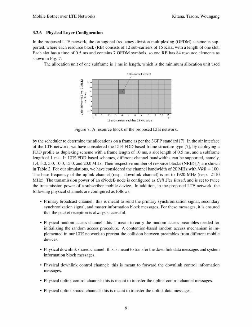
3.2.6 Physical Layer Configuration
In the proposed LTE network, the orthogonal frequency division multiplexing (OFDM) scheme is sup-ported, where each resource block (RB) consists of 12 sub-carriers of 15 KHz, with a length of one slot.Each slot has a time of 0.5 ms and contains 7 OFDM symbols, so one RB has 84 resource elements asshown in Fig. 7.
The allocation unit of one subframe is 1 ms in length, which is the minimum allocation unit used
Figure 7: A resource block of the proposed LTE network.
by the scheduler to determine the allocations on a frame as per the 3GPP standard [7]. In the air interfaceof the LTE network, we have considered the LTE-FDD based frame structure type [7], by deploying aFDD profile as duplexing scheme with a frame length of 10 ms, a slot length of 0.5 ms, and a subframelength of 1 ms. In LTE-FDD based schemes, different channel bandwidths can be supported, namely,1.4, 3.0, 5.0, 10.0, 15.0, and 20.0 MHz. Their respective number of resource blocks (NRB) [7] are shownin Table 2. For our simulations, we have considered the channel bandwidth of 20 MHz with NRB = 100.The base frequency of the uplink channel (resp. downlink channel) is set to 1920 MHz (resp. 2110MHz). The transmission power of an eNodeB node is configured as Cell Size Based, and is set to twicethe transmission power of a subscriber mobile device. In addition, in the proposed LTE network, thefollowing physical channels are configured as follows:
• Primary broadcast channel: this is meant to send the primary synchronization signal, secondarysynchronization signal, and master information block messages. For these messages, it is ensuredthat the packet reception is always successful.
• Physical random access channel: this is meant to carry the random access preambles needed forinitializing the random access procedure. A contention-based random access mechanism is im-plemented in our LTE network to prevent the collision between preambles from different mobiledevices.
• Physical downlink shared channel: this is meant to transfer the downlink data messages and systeminformation block messages.
• Physical downlink control channel: this is meant to forward the downlink control informationmessages.
• Physical uplink control channel: this is meant to transfer the uplink control channel messages.
• Physical uplink shared channel: this is meant to transfer the uplink data messages.
9

Mobile Botnet over LTE Networks Kitana, Traore, Woungang
Table 2: Channel bandwidth parameters.
Channel band-width (MHz)
1.4 3.0 5.0 10.0 15.0 20.0
NRB 6 15 25 50 75 100
4 Mobility Models
To understand the behavior of the proposed mobile botnet and factors that can affect its operations andpropagation, we have studied the impact of cellular devices’ mobility dynamics on the mobile botnetoperations on the proposed LTE network. Two different mobility models are used to simulate the move-ments of mobile devices in the mobile botnet, namely a symmetric mobility model (SMM)) - whichrepresents the uniform movement patterns of mobile devices in the mobile botnet, and an asymmetricmobility model (AMM), which represents the random movement patterns of cellular devices in a mobilebotnet. The AMM model is based on real datasets from taxicab deployments in Shanghai [11] whereasfor the SMM model, a trajectory file generated by the Random WayPoint (RWP) model [10] is used asmovement trajectory file for all cellular devices.
4.1 SMM model
The SMM model is derived from the RWP model. In this model, each mobile device chooses at randoma waypoint w in the LTE network deployment region G and moves to its waypoint with a velocity vchosen randomly in the interval [vmin,vmax], where with vmin > 0 and vmax < ∞. When a mobile devicereaches its waypoint, it remains static for a predefined pause time tp, then starts to move again accordingto the same process. In doing so, the movement period of a mobile device is indexed by a discrete-timeparameter i and a continuous time t. Therefore, the RWP model is represented by a stochastic process{(W1,Tp1,V1), . . . ,(Wi,Tpi,Vk), . . .}, where Wi represents a waypoint in G, Tpi is the pause time in thewaypoint Wi, which is set to 100 seconds, Vi is the velocity of the mobile device during the movementperiod i where i ∈ N. All waypoints Wi are distributed randomly using a uniform distribution over thedeployment region G, except for W0, which is generated by using an initial spatial node distributionfini(x) to randomly place the mobile devices in the LTE network deployment region G at the start of thesimulation. The movement vector from wi−1 to wi is defined as a segment (Si); therefore, the completemovement trace of a mobile device (i.e. its trajectory) is defined as the sequence of these segments, i.e.{S1, . . . ,Si, . . .}= {w1−w0, . . . ,wi−wi−1, . . .}.
In our simulations, the RWP movement model is activated by defining G as a rectangular regionand by specifying the x-y coordinates. according to the following parameters:
• GXMin: this is used to specify the left (west) border of the movement area on the x-axis of G.
• GXMax: this is used to specify the right (east) border of the movement area on the x-axis of G.
• GY Min: this is used to specify the lower (south) border of the movement area on the y-axis of G.
• GY Max: this is used to specify the upper (north) border of the movement area on the y-axis of G.
Table 3 shows the configuration of these parameters. To ensure that all mobile devices in the LTE networkfollow the same movement during simulation, the following steps are taken:
• Before creating the RWP profile, the record trajectory attribute is enabled, which is a feature thatallows the trajectory movement of all or specific mobile devices in the deployment region G to berecorded.
10
Mobile Botnet over LTE Networks Kitana, Traore, Woungang
Table 3: Parameters of the RWP model.
Parameter Value
GXMin -2,500 meter
GXMax 4,000 meter
GY Min -2,598.076 meter
GY Max 2,598.076 meter
Speed 5 meters/second
Pause Time 100 seconds
Starting Time Time that the simulation starts
Stopping Time Time that the simulation ends
• After the RWP profile deployment, the record trajectory attribute value in one of the mobile devicesis enabled, so that its trajectory movement can be recorded and saved.
• Next, the assigned RWP profile is deleted from all the mobile devices and the recorded trajectoryfile to all mobile devices are re-assigned.
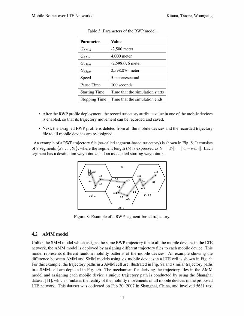
An example of a RWP trajectory file (so-called segment-based trajectory) is shown in Fig. 8. It consistsof 8 segments {S1, . . . ,S8}, where the segment length (li) is expressed as li = ‖Si‖= ‖wi−wi−1‖. Eachsegment has a destination waypoint w and an associated starting waypoint r.
Figure 8: Example of a RWP segment-based trajectory.
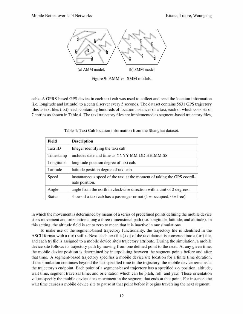
4.2 AMM model
Unlike the SMM model which assigns the same RWP trajectory file to all the mobile devices in the LTEnetwork, the AMM model is deployed by assigning different trajectory files to each mobile device. Thismodel represents different random mobility patterns of the mobile devices. An example showing thedifference between AMM and SMM models using six mobile devices in a LTE cell is shown in Fig. 9.For this example, the trajectory paths in a AMM cell are illustrated in Fig. 9a and similar trajectory pathsin a SMM cell are depicted in Fig. 9b. The mechanism for deriving the trajectory files in the AMMmodel and assigning each mobile device a unique trajectory path is conducted by using the Shanghaidataset [11], which simulates the reality of the mobility movements of all mobile devices in the proposedLTE network. This dataset was collected on Feb 20, 2007 in Shanghai, China, and involved 5631 taxi
11
Mobile Botnet over LTE Networks Kitana, Traore, Woungang
(a) AMM model. (b) SMM model
Figure 9: AMM vs. SMM models.
cabs. A GPRS-based GPS device in each taxi cab was used to collect and send the location information(i.e. longitude and latitude) to a central server every 5 seconds. The dataset contains 5631 GPS trajectoryfiles as text files (.txt), each containing hundreds of location instances of a taxi, each of which consists of7 entries as shown in Table 4. The taxi trajectory files are implemented as segment-based trajectory files,
Table 4: Taxi Cab location information from the Shanghai dataset.
Field Description
Taxi ID Integer identifying the taxi cab
Timestamp includes date and time as YYYY-MM-DD HH:MM:SS
Longitude longitude position degree of taxi cab.
Latitude latitude position degree of taxi cab.
Speed instantaneous speed of the taxi at the moment of taking the GPS coordi-nate position.
Angle angle from the north in clockwise direction with a unit of 2 degrees.
Status shows if a taxi cab has a passenger or not (1 = occupied, 0 = free).
in which the movement is determined by means of a series of predefined points defining the mobile devicesite's movement and orientation along a three-dimensional path (i.e. longitude, latitude, and altitude). Inthis setting, the altitude field is set to zero to mean that it is inactive in our simulations.
To make use of the segment-based trajectory functionality, the trajectory file is identified in theASCII format with a (.trj) suffix. Next, each text file (.txt) of the taxi dataset is converted into a (.trj) file,and each trj file is assigned to a mobile device site's trajectory attribute. During the simulation, a mobiledevice site follows its trajectory path by moving from one defined point to the next. At any given time,the mobile device position is determined by interpolating between the segment points before and afterthat time. A segment-based trajectory specifies a mobile device'site location for a finite time duration;if the simulation continues beyond the last specified time in the trajectory, the mobile device remains atthe trajectory's endpoint. Each point of a segment-based trajectory has a specified x-y position, altitude,wait time, segment traversal time, and orientation which can be pitch, roll, and yaw. These orientationvalues specify the mobile device site's movement in the segment that ends at that point. For instance, thewait time causes a mobile device site to pause at that point before it begins traversing the next segment.
12
Mobile Botnet over LTE Networks Kitana, Traore, Woungang
5 Mobile Botnet Architecture
5.1 Mobile Botnet Setup
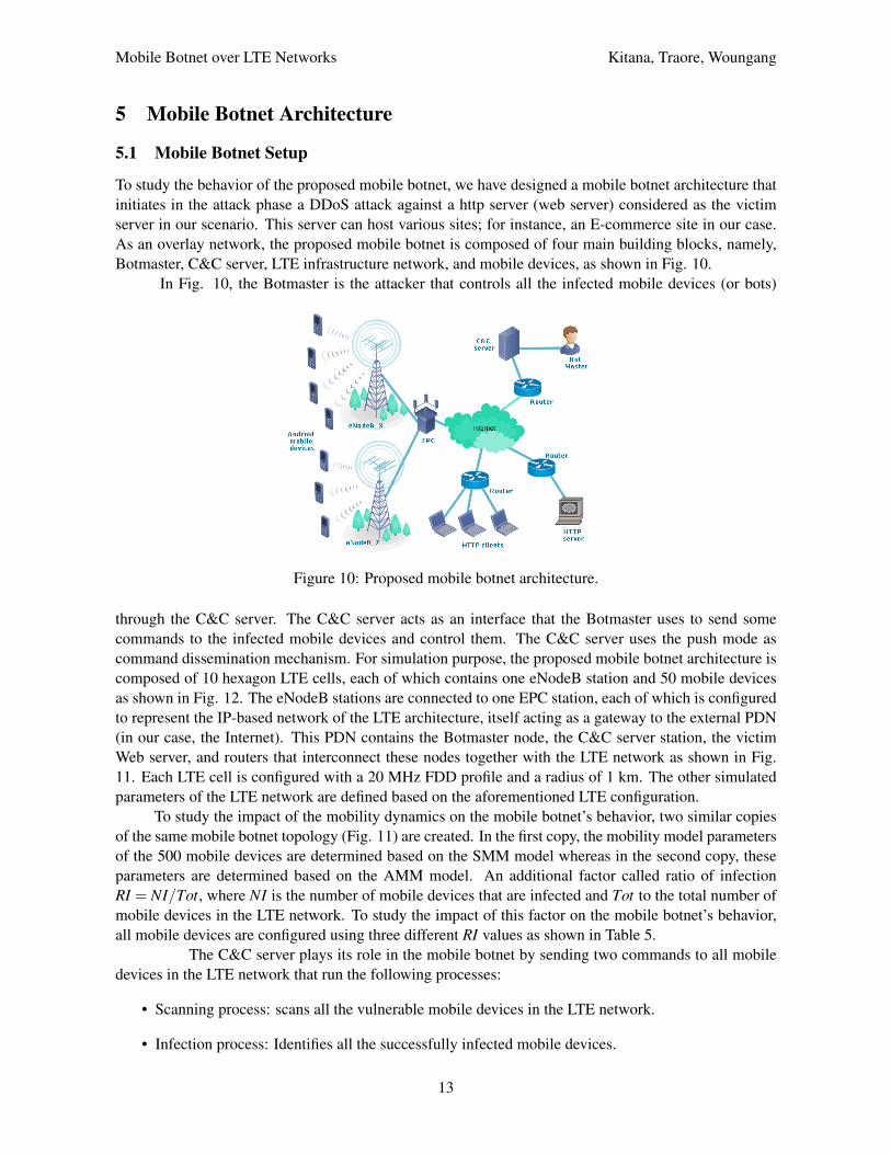
To study the behavior of the proposed mobile botnet, we have designed a mobile botnet architecture thatinitiates in the attack phase a DDoS attack against a http server (web server) considered as the victimserver in our scenario. This server can host various sites; for instance, an E-commerce site in our case.As an overlay network, the proposed mobile botnet is composed of four main building blocks, namely,Botmaster, C&C server, LTE infrastructure network, and mobile devices, as shown in Fig. 10.
In Fig. 10, the Botmaster is the attacker that controls all the infected mobile devices (or bots)
Figure 10: Proposed mobile botnet architecture.
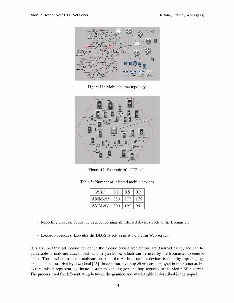
through the C&C server. The C&C server acts as an interface that the Botmaster uses to send somecommands to the infected mobile devices and control them. The C&C server uses the push mode ascommand dissemination mechanism. For simulation purpose, the proposed mobile botnet architecture iscomposed of 10 hexagon LTE cells, each of which contains one eNodeB station and 50 mobile devicesas shown in Fig. 12. The eNodeB stations are connected to one EPC station, each of which is configuredto represent the IP-based network of the LTE architecture, itself acting as a gateway to the external PDN(in our case, the Internet). This PDN contains the Botmaster node, the C&C server station, the victimWeb server, and routers that interconnect these nodes together with the LTE network as shown in Fig.11. Each LTE cell is configured with a 20 MHz FDD profile and a radius of 1 km. The other simulatedparameters of the LTE network are defined based on the aforementioned LTE configuration.
To study the impact of the mobility dynamics on the mobile botnet’s behavior, two similar copiesof the same mobile botnet topology (Fig. 11) are created. In the first copy, the mobility model parametersof the 500 mobile devices are determined based on the SMM model whereas in the second copy, theseparameters are determined based on the AMM model. An additional factor called ratio of infectionRI = NI/Tot, where NI is the number of mobile devices that are infected and Tot to the total number ofmobile devices in the LTE network. To study the impact of this factor on the mobile botnet’s behavior,all mobile devices are configured using three different RI values as shown in Table 5.
The C&C server plays its role in the mobile botnet by sending two commands to all mobiledevices in the LTE network that run the following processes:
• Scanning process: scans all the vulnerable mobile devices in the LTE network.
• Infection process: Identifies all the successfully infected mobile devices.
13
Mobile Botnet over LTE Networks Kitana, Traore, Woungang
Figure 11: Mobile botnet topology.
Figure 12: Example of a LTE cell.
Table 5: Number of infected mobile devices
NIRI 0.8 0.5 0.2
AMM-NI 380 277 176
SMM-NI 300 197 96
• Reporting process: Sends the data concerning all infected devices back to the Botmaster.
• Execution process: Executes the DDoS attack against the victim Web server.
It is assumed that all mobile devices in the mobile botnet architecture are Android based, and can bevulnerable to malware attacks such as a Trojan horse, which can be used by the Botmaster to controlthem. The installation of the malware script on the Android mobile devices is done by repackaging,update attack, or drive-by download [25]. In addition, five http clients are deployed in the botnet archi-tecture, which represent legitimate customers sending genuine http requests to the victim Web server.The process used for differentiating between the genuine and attack traffic is described in the sequel.
14

Mobile Botnet over LTE Networks Kitana, Traore, Woungang
5.2 Attack Setup
A DDoS attack is simulated in the attack phase of the mobile botnet over the LTE network as shownin Fig. 13. In this attack model, the C&C server (controlled by the Botmaster) starts the attack by
Figure 13: DDoS attack model of the mobile botnet.
scanning all the 500 mobile devices of the LTE network in order to identify the ones that are vulnerable.Upon completion of the scanning process, the C&C server sends a command to infect the maximumpossible number of vulnerable devices using a malware (already installed on the mobile devices throughrepackaging, update attack, or drive-by download [25]) as per the following steps:
• All mobile devices are configured using three different RI values as shown in Table 5.
• Based on the activated RI parameter, the Botmaster receives a report message indicating the valueof NI.
Each mobile device infected successfully sends back a notification message to the Botmaster, indicatingits information (unique name, international mobile subscriber identity (IMSI), and IP address). Next, theBotmaster issues a command that instructs the infected devices to send bogus http traffic to the victimWeb server.
The generation of the bogus traffic is different from that of the genuine traffic since it relies on theconsidered traffic profile parameters . As example, for a mobile device to send http traffic, a http profilein the supported profile parameter for that device is identified (if any) and configured. Genuine http trafficare generated by mobile devices that send http traffic based on identified http profiles whereas bogus httptraffic are generated when mobile devices that send http traffic rely on no identified http profiles; in thiscase, the supported profile parameter value is set to none. Bogus traffic and genuine traffic are used torepresent respectively the DDoS attack traffic and the normal http traffic. The latter is generated as perthe method provided in [13] using an average browsing packet size of 1608 bits and an average browsinginter-arrival time of 0.47 seconds. On the other hand, the DDoS attack traffic is generated as per themethod provided in [12], using an inter-arrival time of 0.003 seconds.
In our simulations, the 500 mobile devices are configured with a profile parameter value of none,i.e. the traffic generated from them (via the execution process) are bogus ones. On the other hand, the 5http clients (i.e. legitimate customers) are configured to generate genuine http traffic based on the normalhttp traffic characterization. Both types of traffic are generated for 150 seconds, and a DDoS attack iscreated by overwhelming the victim Web server resources (i.e. CPU and bandwidth) with bogus httprequests over the LTE network. After starting the simulation time at time t = 0 second, the DDoS attackstarts at a random time between t = 100 seconds and t = 110 seconds following these steps:
15

Mobile Botnet over LTE Networks Kitana, Traore, Woungang
• Phase 1: At the start of the DDoS attack, a command is sent to all 500 mobile nodes in an attemptto infect them, and a notification report is sent back to the Botmaster indicating if the infectionsucceeded or did not.
• Phase 2: 150 seconds after the DDoS attack has started, at time t = 250 seconds, another commandis sent that forces only the successfully infected mobile devices to start sending bogus http trafficto the victim E-commerce Web server in an attempt to flood it.
The timeline of the DDoS attack model is depicted in Fig. 14 and algorithm 1 is executed by the C&Cserver to launch the DDoS attack.
Figure 14: DDoS attack model time-line
Algorithm 1 Flooding algorithm run by the C&C server.1: procedure FLOOD
2: Input: N: number of vulnerable mobile nodes in the network.3: At time t = Random (100 seconds, 110 seconds)4: for each vulnerable node i ∈ N do5: Inject the vulnerable nodes with the infection command.6: if infection is successful then7: confirmation messages will be sent to the Botmaster8: end if9: end for
10: At time t = Random (250 seconds, 260 seconds)11: for each successfully infected node j ∈ V where V ⊂ N do12: sends an activation command to each V ( j) to start flooding the victim server.13: end for14: end procedure
6 Simulation Results
The same LTE network parameters are applied to the two mobile botnet scenarios, SMM and AMM. Thesimulation parameters of both scenarios are configured as shown in Table 6, and the RI value of 0.8 isused.
First, the number of infected mobile devices is varied between the SMM and AMM scenarios. Thisvariation is the result of triggering a command of the Phase 1 in the DDoS attack profile of the mobilebotnet. The number of infected mobile devices through the duration of the DDoS attack is depicted in
16

Mobile Botnet over LTE Networks Kitana, Traore, Woungang
Table 6: Simulation parameters
Parameter Value
Mobility Model Random WayPoint, Shanghai taxi dataset
Wireless technology LTE
Pathloss model Free space
Cell Radius 1 km
UE Model LTE mobile node
Number of UE nodes 500
Geographical overlay Hexagon cell
UE Placement Random way
Number of eNodeB stations 10
Number of EPC stations 1
Number of LTE cells 10
Simulation time 720 seconds
Mobility Start time Start of simulation
Mobility Stop time End of simulation
UE transmission power 0.005 watts
eNodeB transmission power 0.011 watts
Channel bandwidth 20 MHz
Duplex scheme FDD
Fig. 15. In this figure, the first spike represents the overlapping of the number of infected mobile devicesbetween the SMM and AMM scenarios at the beginning of Phase 1, which starts at time t = 100 seconds.The second spike represents the number of infected mobile devices of the AMM and SMM scenarios atthe end of the simulation, which is at t = 720 seconds. Clearly, the number of infected mobile devicesin the AMM scenario is higher than that obtained in the SMM scenario. Thus, using the AMM scenarioyields a higher attack impact on the victim Web server compared to using the SMM scenario.
Figure 15: Number of infected mobile devices for AMM vs. SMM.
Second, the relationship between the mobility models and the CPU resource consumption is investi-
17

Mobile Botnet over LTE Networks Kitana, Traore, Woungang
gated, revealing that there is a correlation between the movements patterns of mobile users in the mobilebotnet and the CPU performance as shown in Fig. 16. It can be observed that under the DDoS attack,the AMM scenario consumes more CPU resources than the SMM scenario.
Figure 16: AMM scenario vs. SMM scenario in terms of CPU Utilization (%)
Third, the task processing time consumed by the victim web server is investigated, which representsthe time (in seconds) that was consumed by the victim Web server to process and respond to a request.The results are shown in Fig. 17. It can be observed that the AMM scenario consumes much moretime than the SMM scenario, which is an indication that the probability of rejecting the legitimate httprequests in the AMM scenario is higher than obtained for the SMM scenario, i.e. the AMM scenario ismore destructive compared to the SMM scenario. Fourth, the impact of the AMM and SMM mo-
Figure 17: AMM scenario vs. SMM scenario in terms of task processing time in seconds
bility models on the Web server http traffic load over time is investigated, where the http load representsthe rate at which the http requests from different sessions arrive at the victim Web server. The resultsare shown in Fig. 18. It can be observed that the AMM scenario yields a much higher http load than theSMM scenario does.
Fifth, the impact of the AMM and SMM mobility models on the response time of the legitimaterequests is investigated. The results are shown in Fig. 19. It can be observed that the response time ofthe receiving html objects in the victim Web server in the AMM scenario is much higher compared tothat generated by the SMM scenario during the DDoS attack.
Sixth, the MAC traffic sent by the uplink level of the LTE network, i.e. the overall number of bitssuccessfully transmitted by all the mobile devices in the LTE network toward the victim web server, ismeasured in order to evaluate the correlation between the SMM and AMM scenarios under the controlof the mobile botnet as well as their impact on the LTE network behavior. The results are captured inFig. 20. It can be observed that the number of bits successfully transmitted to the victim Web server is
18

Mobile Botnet over LTE Networks Kitana, Traore, Woungang
Figure 18: AMM scenario vs. SMM scenario in terms of http load
Figure 19: AMM scenario vs. SMM scenario in terms of HTML object response time
higher the AMM scenario compared to that obtained in the SMM scenario in the presence of the DDoSattack.
Figure 20: AMM scenario vs. SMM scenario in terms of Uplink MAC traffic sent
7 Conclusion and Future Work
In this paper, a mobile botnet that conducts a DDoS attack over a LTE network has been proposed. Oursimulation results reveal that using the SMM model is advantageous compared to the AMM model interms of: (1) number of infected mobile devices, (2) CPU resource consumption, (3) task processing timeconsumed, (4) Web server http traffic load over time, (5) receiving html objects, all in the victim Webserver; and (6) the number of bits successfully transmitted to the victim Web server. This suggefslashst
19

Mobile Botnet over LTE Networks Kitana, Traore, Woungang
that using the AMM model would yield a more severe threat impact of the mobile botnet on the victimWeb server compared to using the SMM model. As future work, we plan to investigate other LTE-basedmobility models and study their impact on the behavior of the mobile botnet. We also plan to investigatethe malware propagation impact when more eNodeB stations and EPC nodes are added to the consideredLTE network topology. The botnet model proposed in this work can inspire the design of effective andefficient techniques for detecting and mitigating the impact of mobile botnet.
Acknowledgment
The authors would like to thank the Shanghai Jiao Tong University, China, for providing the access to theShanghai taxi cab trace data, which was obtained from the Wireless and Sensor Networks Lab (WnSN).
References[1] 3gpp ts 24.007 mobile radio interface signalling layer 3; general aspects, rel. 11, section 11.2.3.1.5, june
2012. http://www.3gpp.org/dynareport/24007.htm. [Online; Accessed on May 3, 2016].[2] 3gpp ts 36.133, evolved universal terrestrial radio access (e-utra); requirements for support of radio resource
management, release 11, september 2012. http://www.3gpp.org/dynareport/36133.htm. [Online;Accessed on May 3, 2016].
[3] Bandwidth support in lte standards, qualcomm. https://transition.fcc.gov/bureaus/oet/tac/
tacdocs/meeting71612/PANEL2.3-Gaal-Qualcomm.pdf. [Online; Accessed on May 3, 2016].[4] Datasets and tools by keyword: Dtn. http://crawdad.org/nus/bluetooth/20070903/. [Online; Ac-
cessed on May 3, 2016].[5] Dedicated bearer activation procedure in 3gpp ts 23.401, general packet radio service (gprs) enhancements
for evolved universal terrestrial radio access network (e-utran) access, release 11, sept. 2012. http://www.3gpp.org/DynaReport/23401.htm. [Online; Accessed on May 3, 2016].
[6] Epfl dataset. http://cvlab.epfl.ch/data/pose. [Online; Accessed on May 3, 2016].[7] Lte-a 3gpp. http://www.3gpp.org/technologies/keywords-acronyms/97-lte-advanced. [On-
line; Accessed on May 3, 2016].[8] New york city subway dataset. https://jameskao.me/analyzing-the-nyc-subway-dataset/. [On-
line; Accessed on May 3, 2016].[9] Rate of lte deployment increasing report, gsa press release. http://www.3gpp.org/news-events/
partners-news/1561-rate-of-lte-deployment-increasing.. [Online; Accessed on May 3, 2016].[10] Riverbed modeler. http://www.riverbed.com/products/performance-managementcontrol/
network-performance-management/network-simulation.html. [Online; Accessed on May 3, 2016].[11] Shanghai jiao tong university. suvnet-trace data. http://wirelesslab.sjtu.edu.cn. [Online; Accessed
on May 3, 2016].[12] K. Arora, K. Kumar, and M. Sachdeva. Characterizing ddos attack distributions from emulation based ex-
periments on deter testbed. In The 2011 International Conference on Advanced Computing, Networking andSecurity (ADCONS’11), Surathkal, India, December 16-18, 2011, Revised Selected Papers, volume 7135 ofLecture Notes in Computer Science, pages 541–550. Springer, 2012.
[13] M. Bekhouri and R. Nossenson. Application benchmark for cellular backhaul network. In Proc. of the 11thInternational Conference on Wireless and Mobile Communications (ICWMC’15), St. Julians, Malta, pages51–56. IARIA, October 2015.
[14] D. Evans, J. Groves, and W. Croft. Operator group ranking, q2 2014, chinese carriers dominate globaloperator ranking as m&a deals shake up us market. https://www.gsmaintelligence.com/research/
2014/09/operator-group-ranking-q2-2014/444/l/. [Online; Accessed on May 3, 2016].[15] G. Geng, G. Xu, M. Zhang, Y. Guo, G. Yang, and C. Wei. The design of sms based heterogeneous mobile
botnet. Journal of Computers, 7(1):235–243, January 2012.
20
Mobile Botnet over LTE Networks Kitana, Traore, Woungang
[16] J. Hua and K. Sakurai. Botnet command and control based on short message service and human mobility.Journal of Computer Networks, Elsevier, 57(2):579–597, February 2013.
[17] A. Karim, S. A. A. Shah, and R. Salleh. Mobile botnet attacks: a thematic taxonomy. In New Perspectives inInformation Systems and Technologies, Springer, Vol. 2, volume 276 of Advances in Intelligent Systems andComputing, pages 153–164. Springer International Publishing, 2014.
[18] F. Li, Y. Yang, and J. Wu. Cpmc: An efficient proximity malware coping scheme in smartphone-based mobilenetworks. In Proc. of the 29th IEEE Conference on Computer Communications (INFOCOM’10), San Diego,CA, USA, pages 1–9. IEEE, March 2010.
[19] Z. Lu, W. Wang, and C. Wang. How can botnets cause storms? understanding the evolution and impact ofmobile botnets. In Proc. of the 33rd Annual IEEE International Conference on Computer Communications(INFOCOM’14), Toronto, ON, Canada, pages 1501–1509. IEEE, April-May 2014.
[20] K. Singh, S. Sangal, N. Jain, P. Traynor, and W. Lee. Evaluating bluetooth as a medium for botnet com-mand and control. In Proc. of the 7th Conference on Detection of Intrusions and Malware & VulnerabilityAssessment (DIMVA’10), Bonn, Germany, pages 61–80. IEEE, July 2010.
[21] C. Szongott, B. Henne, and M. Smith. Evaluating the threat of epidemic mobile malware. In Proc. of the8th IEEE International Conference on Wireless and Mobile Computing, Networking and Communications(WiMob’12), Barcelona, Spain, pages 443–450. IEEE, October 2012.
[22] P. Traynor, M. Lin, M. Ongtang, V. Rao, T. Jaeger, P. McDaniel, and T. L. Porta. On cellular botnets:measuring the impact of malicious devices on a cellular network core. In Proc. of the 16th ACM Conferenceon Computer and Communications Security (CCS’09), Chicago, IL, USA, pages 223–234. ACM, November2009.
[23] C. Xiang, F. Binxing, Y. Lihua, L. Xiaoyi, and Z. Tianning. Andbot: towards advanced mobile botnets. InProc. of the 4th USENIX Conference on Large-scale Exploits and Emergent Threats (LEET’11), Boston, MA,USA. USENIX Association, March 2011.
[24] Y. Zeng, X. Hu, and K. G. Shin. How to construct a mobile botnet? In Proc. of the 40th Annual IEEE/IFIPInternational Conference on Dependable Systems and Networks (DSN’10), Chicago, IL, USA. IEEE, June-July 2010.
[25] Y. Zhou and X. Jiang. Dissecting android malware: Characterization and evolution. In Proc. of the 33rdannual IEEE Symposium on Security and Privacy, San Francisco, CA, USA, pages 95–109. IEEE, May 2012.
——————————————————————————
Author Biography
Asem Kitana is a Ph.D. candidate in the Electrical and Computer Engineering De-partment at the University of Victoria, BC, Canada. He received his M.Sc. in Com-puter Network Security from DePaul University in Chicago, IL, USA in 2007. Hehas 4 years of technical experience in network security technologies including Intru-sion Prevention Systems, Intrusion Detection Systems, Firewall Systems, and SmartSecurity Solutions. He is currently a research assistant and member of the Infor-mation Security and Object Technology (ISOT) Lab at the University of Victoria
(http://www.isot.ece.uvic.ca). His research interests include mobile botnet, mobile security and privacy,distributed denial of service attacks detection algorithms, telecommunication security, and malware-based threats analysis.
21
Mobile Botnet over LTE Networks Kitana, Traore, Woungang
Issa Traore is the co-founder of Plurilock Security Solutions Inc. (www.plurilock.com)He has been with the faculty of the Electrical and Computer Engineering Departmentof the University of Victoria since 1999, where he is currently a Professor. Dr. Traoreis also the founder and Director of the Information Security and Object Technology(ISOT) Lab (www.isot.ece.uvic.ca). He obtained in 1998 a PhD in Software Engi-neering from the Institute Nationale Polytechnique of Toulouse, France. His mainresearch interests are biometrics technologies, intrusion detection systems, and soft-
ware security.
Isaac Woungang is a Professor at the Department of Computer Science at RyersonUniversity and Director of the Distributed Applications and Broadband (DABNEL)Lab. He received his Ph.D degree in Mathematics from the University of Toulon,France, in 1994. His current research interests include network security, radio re-source management in next generation wireless networks, and cloud computing. Hehas published 8 books and over 90 refereed technical articles in scholarly internationaljournals and proceedings of international conferences. He has served as Associate
Editor of the Computers and Electrical Engineering (Elsevier), and the International Journal of Com-munication Systems (Wiley). Since January 2012, He is the Chair of Computer Chapter, IEEE TorontoSection.
22