Impact strength of dissimilar joints for the automotive ... · 2.4 Strength prediction of single...
120
Impact strength of dissimilar joints for the automotive industry Submitted by: Paulo David Pereira Nunes MSc THESIS Supervised by: Lucas F. M. da Silva Co-supervised by: Eduardo A. S. Marques José J. M. Machado Master Integrated in Mechanical Engineering (January of 2018)
Transcript of Impact strength of dissimilar joints for the automotive ... · 2.4 Strength prediction of single...

Impact strength of dissimilar joints for the automotive industry
Submitted by:
Paulo David Pereira Nunes
MSc THESIS
Supervised by: Lucas F. M. da Silva
Co-supervised by: Eduardo A. S. Marques
José J. M. Machado
Master Integrated in Mechanical Engineering
(January of 2018)

Impact strength of dissimilar joints for the automotive industry
ii

Impact strength of dissimilar joints for the automotive industry
iii
Acknowledgements
First of all, I would like to express my gratitude to Professor Lucas da Silva, my
supervisor, for the opportunity to collaborate with him in this work.
I would like to thank Eduardo Marques and José Machado, my co-supervisors, for the
time spent, and the complete availability during the development and execution of this
dissertation.
To the adhesive group for all the tips given, and for helping me when it´s been necessary.
I wish to express thanks to Nagase ChemteX® (Osaka, Japan) for providing the adhesive
for this work.
I also wish to acknowledge the support provided by the project NORTE-01-0145-
FEDER-000022 - SciTech - Science and Technology for Competitive and Sustainable
Industries, co-financed by Programa Operacional Regional do Norte (NORTE2020), through
Fundo Europeu de Desenvolvimento Regional (FEDER).
Lastly and the most important, I would like to express my gratitude to my family and
friends, especially my parents and sister, for the support, encouragement and patience given
during this long journey.
iv
Abstract
The automotive industry is currently facing challenges in the reduction of emissions and
fuel consumption. These targets can only be achieved with the use of lightweight materials for
the vehicle structures, such as carbon fibre composites and aluminium alloys. The construction
techniques for vehicle bodies with these materials differ greatly from the techniques used for
the most commonly used steel bodies, with adhesive bonding being used extensively due to its
capability to bond dissimilar materials. However, the use of adhesive bonding poses several
challenges to the automotive engineers, as the dissimilar bonded joints must be designed to
perform well under impact and extreme temperature conditions.
The aim of this work is to understand and predict the behaviour of dissimilar adhesive
joints, using composite and aluminium adherends, under quasi-static and impact loads. A
variety of testing temperatures (ranging from -30 to 80ºC) was considered, taking into account
the requirements for the automotive industry. A numerical simulation procedure was also
performed in parallel and produced numerical models which where validated against the
experimentally obtained data in both quasi-static and impact conditions. It was possible to
conclude that dissimilar adhesive joints, if used in conjunction with modern crash resistant
adhesives, can effectively be used for the construction of automotive structures, without
significant sacrifices in joint performance, with good energy absorption capabilities under
impact. Moreover, their performance can also be simulated using advanced cohesive zone
models minimizing the need to perform extensive experimental impact testing.
v
Resumo
Atualmente, a indústria automóvel enfrenta desafios significativos na redução de emissões
e consumo de combustível. Esses objetivos só poderão ser alcançados pelo uso de materiais
leves nas estruturas do veículo, tais como compósitos de fibra de carbono e ligas de alumínio.
As técnicas de construção de estruturas de veículos com recurso a estes materiais diferem muito
das técnicas utilizadas em estruturas de aço, sendo adotado o uso de ligações adesivas devido à
sua capacidade de unir materiais dissimilares. No entanto, o uso de adesivos estruturais coloca
novos desafios aos engenheiros de projeto, já que as juntas adesivas de substratos dissimilares
devem ser projetadas para suportar condições de impacto e de temperatura extrema.
Com este estudo pretendeu-se determinar e compreender o comportamento de juntas
adesivas com materiais similares, usando aderentes de material compósito e de alumínio,
sujeitos a carregamentos quase-estáticos e de impacto. Os ensaios foram realizados numa ampla
gama de temperaturas (variando de -30 a 80ºC), levando em consideração os requisitos da
indústria automóvel. Um procedimento de simulação numérico foi realizado em paralelo ao
trabalho laboratorial, gerando modelos numéricos que, após validação experimental,
permitiram prever o comportamento mecânico das juntas em condições quasi-estáticas e de
impacto. Modelos de dano coesivas foram utilizados para simular a falha do adesivo e a
delaminação dos compósitos, enquanto modelos de dano foram usados para simular
deformação plástica e falha nos substratos de alumínio. Concluiu-se que é possível utilizar
juntas adesivas dissimilares na construção de estruturas de veículos, sem ser necessário
sacrificar o comportamento mecânico da ligação e com boas capacidades de absorção de
energia ao impacto. Foi também possível concluir que a aplicação de modelos de dano coesivo
permite simular com sucesso a performance deste tipo de juntas dissimilares, reduzindo assim
a necessidade de efetuar ensaios de impacto.
vi
Contents
Acknowledgements ................................................................................................................... iii
Abstract ..................................................................................................................................... iv
Resumo ..................................................................................................................................... v
Contents .................................................................................................................................... vi
List of acronyms ........................................................................................................................ ix
Notation ..................................................................................................................................... x
List of figures ............................................................................................................................ xii
List of tables ........................................................................................................................... xvii
1 Introduction .......................................................................................................................... 1
1.1 Background and motivation ................................................................................................. 1
1.2 Objectives ........................................................................................................................... 1
1.3 Research methodology ....................................................................................................... 2
1.4 Dissertation outline ............................................................................................................. 2
2 Literature Review ................................................................................................................. 4
2.1 Survey of adhesive joints .................................................................................................... 4
2.1.1 Failure modes and joint design………………………………………………………...6
2.1.2 Types of adhesives……………………………………………………………………..9
2.2 Adhesive joints in the automotive industry ......................................................................... 10
2.2.1 Structural adhesives used in the automotive industry……………………………..11
2.2.2 Substrates used in the automotive industry…………………………………………13
2.3 Effect of temperature and impact loads ............................................................................. 18
2.3.1 Adhesives under impact loads and temperature influence………………………...20
2.3.2 Aluminium substrates under impact loads and temperature………………………21
2.3.3 CFRP substrates under impact loads and temperature……………………………23
2.4 Strength prediction of single lap joints ............................................................................... 26
2.4.1 Numerical methods……………………………………………………………………26
3 Experimental details ........................................................................................................... 31
vii
3.1 Material selection .............................................................................................................. 31
3.2 Adhesive characterization ................................................................................................. 33
3.2.1 Tensile test……………………………………………………………………………..33
3.2.2 Double cantilever beam……………………………………………………………….40
3.3 Fabrication and testing of single lap joints ......................................................................... 50
3.3.1 CFRP plates manufacturing………………………………………………………….50
3.3.2 Joints
manufacturing…………………………………………………………………………………52
3.3.3 Joints configurations…………………………………………………………………..53
3.3.4 Testing procedure……………………………………………………………………..54
4 Numerical simulation details ............................................................................................... 56
4.1 Cohesive zone modelling .................................................................................................. 56
4.2 Quasi-static model ............................................................................................................ 56
4.3 Dynamical model .............................................................................................................. 60
5 Results and discussion ....................................................................................................... 63
5.1 Experimental results ......................................................................................................... 63
5.1.1 Quasi-static tests………………………………………………………………………63
5.1.2 Impact tests…………………………………………………………………………….71
5.1.3 Combined temperature-strain rate analysis………………………………………...78
5.2 Numerical results of SLJs.................................................................................................. 88
5.2.1 Quasi-static…………………………………………………………………………….89
5.2.2 Impact…………………………………………………………………………………..92
6 Conclusions ........................................................................................................................ 95
7 Future works ...................................................................................................................... 97
References .............................................................................................................................. 98

viii

ix
List of acronyms
CBBM Compliance based beam method
CBT Corrected beam theory
CCM Compliance calibration method
CFRP Carbon fibre reinforced polymer
CZM Cohesive zone model
DCB Double cantilever beam
DLJ Double lap joint
ENF End notched flexure
FEA Finite element analysis
FPZ Fracture plastic zone
RT Room temperature
LT Low temperature
HT High temperature
SLJ Single lap joint
x
Notation
𝑎 Crack length
𝑎𝑒q Equivalent crack’s length
𝐶 Compliance
𝐸 Young’s modulus
𝐸𝑥 Longitudinal normal modulus
𝐺𝑥𝑦 Longitudinal shear modulus
𝐸f Corrected bending modulus
𝐺 Shear modulus
𝐺𝐼c Critical strain energy release rate or fracture toughness in mode I
𝐺𝐼𝐼c Critical strain energy release rate or fracture toughness in mode II
𝑘 Shear stress distribution constant
𝐾 Elastic constitutive matrix
𝑃 Applied force
𝑇𝑔 Glass transition temperature
𝑡 Thickness
𝑡𝑛 Cohesive strength in tension
𝑡𝑠 Cohesive strength in shear
𝑤 Width of the specimen
σ Tensile strength
𝛿𝑜,𝑖 Cohesive strength critical relative displacement
𝛿𝑚𝑎𝑥,𝑖 Maximum relative displacement

xi
𝛿 Displacement
𝛥 Correction factor of crack’s length
𝑣 Poisson’s ratio

xii
List of figures
Figure 1 - Comparison between riveted and adhesive bonded joints [1]. .................................. 5
Figure 2 - Representation of failure modes: cohesion and adhesion [1]. ................................... 6
Figure 3 - Failure modes with composite substrates [7]. ............................................................ 7
Figure 4 - Types of stresses in adhesive joints. (a) normal (or direct) stress, (b) shear stress, (c)
cleavage, (d) peel stress (adapted from [5]). .............................................................................. 8
Figure 5 - Adhesive bonded joints configurations: (a) Single lap joint, (b) Double lap joint, (c)
Double scarf joint, (d) double stepped-lap joint (adapted from [7]). ......................................... 9
Figure 6 - Landscape of adhesives for structural automotive applications [1]. ........................ 11
Figure 7 - Properties comparison [9]. ....................................................................................... 13
Figure 8 - Types of composite materials [17]........................................................................... 16
Figure 9 - Examples of configurations for plies orientation [19]. ............................................ 17
Figure 10 - Overview of ply-level failure modes [21].............................................................. 18
Figure 11 - Effect of strain rate in failure load of joints with aluminium substrates and three
different adhesives. (Adapted from Harris and Adams, 1985) [25]. ........................................ 19
Figure 12 - Absorbed energy at impact conditions for three types of substrates and two
adhesives. (Adapted from Harris and Adams, 1985) [25]. ....................................................... 20
Figure 13 - Representative XN1244 adhesive tensile stress–strain curves as a function of
temperature and test speed (the curves for 150◦C — 0.1 mm/min and 150◦C — 1 mm/min are
nearly coincident) [27].............................................................................................................. 21
Figure 14 - Representative true stress versus true plastic strain curves at wide range of strain
rates for AA6060 T6 and AA6082 T6 alloys0 [36]. ................................................................. 22
Figure 15 - (a) Dependence of the strain rate on modulus, (b) Dependence of the strain rate on
tensile strength. [37]. ................................................................................................................ 23
Figure 16 - Stress–strain curves for unidirectional laminate, (a)longitudinal direction, (b)
transversal direction, at 20 and 60°C. Strain rate around 750 s-1 [39]..................................... 24
Figure 17 - GIc of unidirectional CFRP as function of strain rate and temperature [40]. ........ 25
Figure 18 - GIIc of unidirectional CFRP as function of strain rate and temperature [41]. ........ 25
xiii
Figure 19 - The three modes of loading [1]. ............................................................................. 27
Figure 20 - Representation of the damage zone and corresponding bi-linear traction-separation
law in an adhesively bonded joint [55]. .................................................................................... 28
Figure 21 - Example of the triangular traction-separation law [56]. ........................................ 29
Figure 22 - Traction-separation law with pure and mixed laws [58]. ...................................... 30
Figure 23 - Yield stress versus plastic strain of the aluminium alloys used (AA5754 H22 and
AA6060 T6). ............................................................................................................................. 33
Figure 24 - Geometry of bulk specimens according to EN ISO 527-2 (dimensions in mm) [60].
.................................................................................................................................................. 34
Figure 25 - Mould for producing the bulk specimens with steel plates and silicone rubber frame.
.................................................................................................................................................. 34
Figure 26 - Cure cycle of Nagase-ChemteX adhesive XNR6852 E-3. .................................... 35
Figure 27 - INSTRON® universal test machine. ...................................................................... 36
Figure 28 - Young´s modulus of adhesive XNR6822E-3 as a function of strain rate. ............. 37
Figure 29 - Tensile strength of adhesive XNR6822E-3 as a function of strain rate................. 38
Figure 30 - Values of Young´s modulus of adhesive XNR6852 E-3 estimated for impact
conditions.................................................................................................................................. 39
Figure 31 - Values of tensile strength of adhesive XNR6852 E-3 estimated for impact
conditions.................................................................................................................................. 39
Figure 32 - DCB specimen geometry (dimensions in mm). ..................................................... 40
Figure 33 - Adhesive applied in the open substrates. ............................................................... 40
Figure 34 - Shot blasting machine. ........................................................................................... 41
Figure 35 - Mixing machine SpeedMixer® DAC 150.1 FVZ-K. ............................................. 42
Figure 36 - DCB setup. ............................................................................................................. 43
Figure 37 - Loading scheme of the DCB specimen. ................................................................. 43
Figure 38 - Representation of linear regression of the correction crack length factor [66]. .... 45
Figure 39 - Schematic representation of the FPZ (adapted from [67]). ................................... 46
Figure 40 - Results of fracture toughness in mode I (GIC) for adhesive XNR6852 E-3 as a
function of strain rate and temperature. .................................................................................... 47
xiv
Figure 41 - Example of R-curve from the DCB test performed at 10 mm/min for a testing
temperature of 24°C.................................................................................................................. 48
Figure 42 - Example of failure surface of a DCB..................................................................... 48
Figure 43 - Extrapolation of values of fracture toughness in mode I (GIC) under impact
conditions as a function of temperature. ................................................................................... 49
Figure 44 - Hot press pressure machine. .................................................................................. 51
Figure 45 - Cutting machine used for to cut the squares of CFRP. .......................................... 52
Figure 46 - Mould used to manufacture SLJs. .......................................................................... 53
Figure 47 - Geometry of SLJ specimens (dimensions in mm). ................................................ 54
Figure 48 - Elements introduced in FE software for the static analysis. .................................. 57
Figure 49 - Triangular law for adhesive XNR6852 E-3 in quasi-static conditions. ................. 58
Figure 50 - Triangular law for CFRP at quasi-static conditions............................................... 58
Figure 51 - Boundary conditions applied for the quasi-static model. ...................................... 59
Figure 52 - Representative mesh in the overlap area................................................................ 59
Figure 53 - Boundary conditions applied for the impact model. .............................................. 60
Figure 54 - Triangular law for adhesive XNR6852 E-3 in impact conditions. ........................ 61
Figure 55 - Triangular law for CFRP in impact conditions. ..................................................... 62
Figure 56 - P-δ curves of SLJs using similar substrates tested at quasi-static conditions and RT.
.................................................................................................................................................. 64
Figure 57 - Failure load of SLJs using similar substrates (CFRP and aluminium alloys) tested
at quasi-static conditions as a function of temperature............................................................. 66
Figure 58 - Energy absorbed by SLJs using similar substrates (CFRP and aluminium alloys)
tested at quasi-static conditions as a function of temperature. ................................................. 67
Figure 59 - Failure load of SLJs using dissimilar substrates (CFRP and aluminium alloys) tested
at quasi-static conditions as a function of temperature............................................................. 70
Figure 60 - Energy absorbed by SLJs using dissimilar substrates (CFRP and aluminium alloys)
tested at quasi-static conditions as a function of temperature. ................................................. 71
Figure 61 - Failure load of SLJs using similar substrates (CFRP and aluminium alloys) tested
at impact conditions as a function of temperature. ................................................................... 73

xv
Figure 62 - Energy absorbed by SLJs using similar substrates (CFRP and aluminium alloys)
tested at impact conditions as a function of temperature. ......................................................... 74
Figure 63 - P-δ of SLJs using CFRP similar substrates tested at impact conditions as a function
of temperature. .......................................................................................................................... 75
Figure 64 - Representative scheme of frictional sliding phenomenon. .................................... 75
Figure 65 - Failure load of SLJs using dissimilar substrates (CFRP and aluminium alloys) tested
at impact conditions as a function of temperature. ................................................................... 77
Figure 66 - Energy absorbed by SLJs using dissimilar substrates (CFRP and aluminium alloys)
tested at impact conditions as a function of temperature. ......................................................... 78
Figure 67 - Failure load of SLJs with AA5754 H22 similar substrates as function of temperature
and strain rate............................................................................................................................ 79
Figure 68 - Failure load of SLJs with AA6060 T6 similar substrates as function of temperature
and strain rate............................................................................................................................ 79
Figure 69 - Failure load of SLJs with CFRP similar substrates as function of temperature and
strain rate. ................................................................................................................................. 80
Figure 70 - Energy absorbed by SLJs with AA5754 H22 similar substrates as function of
temperature and strain rate. ...................................................................................................... 81
Figure 71 - Energy absorbed by SLJs with AA6060 T6 similar substrates as function of
temperature and strain rate. ...................................................................................................... 81
Figure 72 - Energy absorbed by SLJs with CFRP similar substrates as function of temperature
and strain rate............................................................................................................................ 82
Figure 73 - P-δ curves of SLJs with AA6060 T6 similar substrates tested at RT as function of
strain rate. ................................................................................................................................. 83
Figure 74 - Stress propagation through the SLJ in impact conditions...................................... 83
Figure 75 - Stress propagation through the SLJ in quasi-static conditions. ............................. 84
Figure 76 - Failure load of SLJs with AA5754 H22 + CFRP dissimilar substrates as function
of temperature and strain rate. .................................................................................................. 85
Figure 77 - Failure load of SLJs with AA6060 T6 + CFRP dissimilar substrates as function of
temperature and strain rate. ...................................................................................................... 85
xvi
Figure 78 - Failure load of SLJs with AA5754 H22 + AA6060 T6 dissimilar substrates as
function of temperature and strain rate. .................................................................................... 86
Figure 79 - Energy absorbed by SLJs with AA5754 H22 + CFRP dissimilar substrates as
function of temperature and strain rate. .................................................................................... 87
Figure 80 - Energy absorbed by SLJs with AA6060 T6 + CFRP dissimilar substrates as function
of temperature and strain rate. .................................................................................................. 87
Figure 81 - Energy absorbed by SLJs with AA5754 H22 + AA6060 T6 dissimilar substrates as
function of temperature and strain rate. .................................................................................... 88
Figure 82 - Comparison between experimental and numerical P-δ curves of SLJs with similar
substrates of AA6060 T6 under quasi-static conditions. .......................................................... 89
Figure 83 - Comparison between experimental and numerical P-δ curves of SLJs with similar
substrates of CFRP under quasi-static conditions. ................................................................... 90
Figure 84 - Comparison between experimental and numerical P-δ curves of SLJs with dissimilar
substrates of AA6060 T6 + CFRP under quasi-static conditions. ............................................ 91
Figure 85 - Comparison between experimental and numerical P-δ curves of SLJs with similar
substrates of AA6060 T6 under impact conditions. ................................................................. 92
Figure 86 - Comparison between experimental and numerical P-δ curves of SLJs with similar
substrates of CFRP under impact conditions. ........................................................................... 93
Figure 87 - Comparison between experimental and numerical P-δ curves of SLJs with dissimilar
substrates of AA6060 T6 + CFRP under impact conditions. ................................................... 94
xvii
List of tables
Table 1 - Example of the mechanical properties of some structural adhesives (adapted from
[7]). ........................................................................................................................................... 12
Table 2 - Comparison between aluminium alloys used in different car components in Europe
versus North America [11]. ...................................................................................................... 15
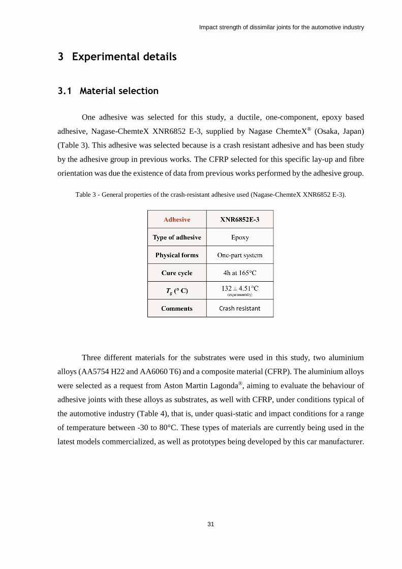
Table 3 - General properties of the crash-resistant adhesive used (Nagase-ChemteX XNR6852
E-3). .......................................................................................................................................... 31
Table 4 - Designation of substrates tested. ............................................................................... 32
Table 5 - Elastic properties of the aluminium alloys used (AA5754 H22 and AA6060 T6). .. 32
Table 6 - Properties of pre-preg SEAL® Texipreg HS 160 RM [65]. ..................................... 50
Table 7 - Different combinations of similar and dissimilar SLJs. ............................................ 54
Table 8 - Failure surfaces of SLJs using similar substrates (CFRP and aluminium alloys) tested
at quasi-static conditions as a function of temperature............................................................. 65
Table 9 - Failure surfaces of SLJs using dissimilar substrates (CFRP and aluminium alloys)
tested at quasi-static conditions as a function of temperature. ................................................. 69
Table 10 - Failure surfaces of SLJs using similar substrates (CFRP and aluminium alloys) tested
at impact conditions as a function of temperature. ................................................................... 72
Table 11 - Failure surfaces of SLJs using dissimilar substrates (CFRP and aluminium alloys)
tested at impact conditions as a function of temperature. ......................................................... 76
Impact strength of dissimilar joints for the automotive industry
1
1 Introduction
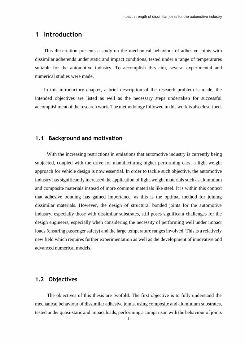
This dissertation presents a study on the mechanical behaviour of adhesive joints with
dissimilar adherends under static and impact conditions, tested under a range of temperatures
suitable for the automotive industry. To accomplish this aim, several experimental and
numerical studies were made.
In this introductory chapter, a brief description of the research problem is made, the
intended objectives are listed as well as the necessary steps undertaken for successful
accomplishment of the research work. The methodology followed in this work is also described.
1.1 Background and motivation
With the increasing restrictions in emissions that automotive industry is currently being
subjected, coupled with the drive for manufacturing higher performing cars, a light-weight
approach for vehicle design is now essential. In order to tackle such objective, the automotive
industry has significantly increased the application of light-weight materials such as aluminium
and composite materials instead of more common materials like steel. It is within this context
that adhesive bonding has gained importance, as this is the optimal method for joining
dissimilar materials. However, the design of structural bonded joints for the automotive
industry, especially those with dissimilar substrates, still poses significant challenges for the
design engineers, especially when considering the necessity of performing well under impact
loads (ensuring passenger safety) and the large temperature ranges involved. This is a relatively
new field which requires further experimentation as well as the development of innovative and
advanced numerical models.
1.2 Objectives
The objectives of this thesis are twofold. The first objective is to fully understand the
mechanical behaviour of dissimilar adhesive joints, using composite and aluminium substrates,
tested under quasi-static and impact loads, performing a comparison with the behaviour of joints
Impact strength of dissimilar joints for the automotive industry
2
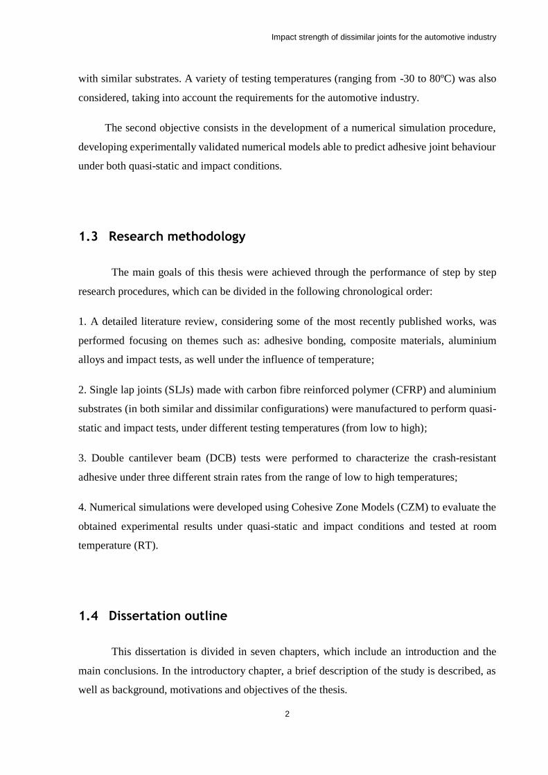
with similar substrates. A variety of testing temperatures (ranging from -30 to 80ºC) was also
considered, taking into account the requirements for the automotive industry.
The second objective consists in the development of a numerical simulation procedure,
developing experimentally validated numerical models able to predict adhesive joint behaviour
under both quasi-static and impact conditions.
1.3 Research methodology
The main goals of this thesis were achieved through the performance of step by step
research procedures, which can be divided in the following chronological order:
1. A detailed literature review, considering some of the most recently published works, was
performed focusing on themes such as: adhesive bonding, composite materials, aluminium
alloys and impact tests, as well under the influence of temperature;
2. Single lap joints (SLJs) made with carbon fibre reinforced polymer (CFRP) and aluminium
substrates (in both similar and dissimilar configurations) were manufactured to perform quasi-
static and impact tests, under different testing temperatures (from low to high);
3. Double cantilever beam (DCB) tests were performed to characterize the crash-resistant
adhesive under three different strain rates from the range of low to high temperatures;
4. Numerical simulations were developed using Cohesive Zone Models (CZM) to evaluate the
obtained experimental results under quasi-static and impact conditions and tested at room
temperature (RT).
1.4 Dissertation outline
This dissertation is divided in seven chapters, which include an introduction and the
main conclusions. In the introductory chapter, a brief description of the study is described, as
well as background, motivations and objectives of the thesis.
Impact strength of dissimilar joints for the automotive industry
3
The chapter regarding the literature review comprehends a brief description of adhesive
bonding, and considerations regarding the mechanical properties of different types of adhesives.
Once a structural adhesive was used in this work, a detailed description was performed on its
mechanical properties under the influence of strain rates and temperature. The mechanical
properties of the CFRP used were analysed under different strain rates and testing temperatures.
The quasi-static and impact behaviour of SLJs was considered.
The experimental details chapter clarifies in detail the manufacturing process of the
SLJs tested, the specimens’ geometry and testing procedures.
The numerical details chapter reports the 2D finite element models built, both under
quasi-static and impact simulations.
The experimental results chapter presents the results of the adhesive characterization
regarding the fracture energy in mode I as a function of strain rate and testing temperature, as
well the quasi-static and impact tests of SLJs as a function of temperature. Failure loads and
energy absorbed, fracture modes and the corresponding simulations are also presented.
The last two sections of this document are the conclusions and future works. Here,
conclusions are drawn regarding the main topics of research, complemented by a discussion of
the most relevant suggestions for further work.
Impact strength of dissimilar joints for the automotive industry
4
2 Literature Review
2.1 Survey of adhesive joints
An adhesive joint is a bonded connection between two similar or different materials using
non-metallic fillers (adhesives). The materials which are joined together by the adhesive are
commonly designated as substrate or substrates [1].
According to Adams and Wake [2] an adhesive can be defined as a material which, when
applied to surfaces, can join them together and resist separation. Adhesive is the general term
and includes cement, glue, paste, etc. It´s known that adhesives are used for centuries, since
biblical times. For example early hunters used beeswax to join feathers to arrows to improve
their aim, this can be considered as a primitive adhesive [3].
In the last century, or so, with the appearance of the first synthetic polymers, namely
epoxy resins, engineers started to look to adhesives as a meaningful alternative to bolting,
riveting, brazing and welding in structural bonding, thus leading to creation of the structural
adhesive [4]. Structural adhesives can be defined as an adhesive used when the load requirement
to cause separation is substantial such that the adhesive provides for the major strength and
stiffness of the structure [2].
When compared with more traditional techniques for joining materials, adhesives can
offer some advantages such as [5]:
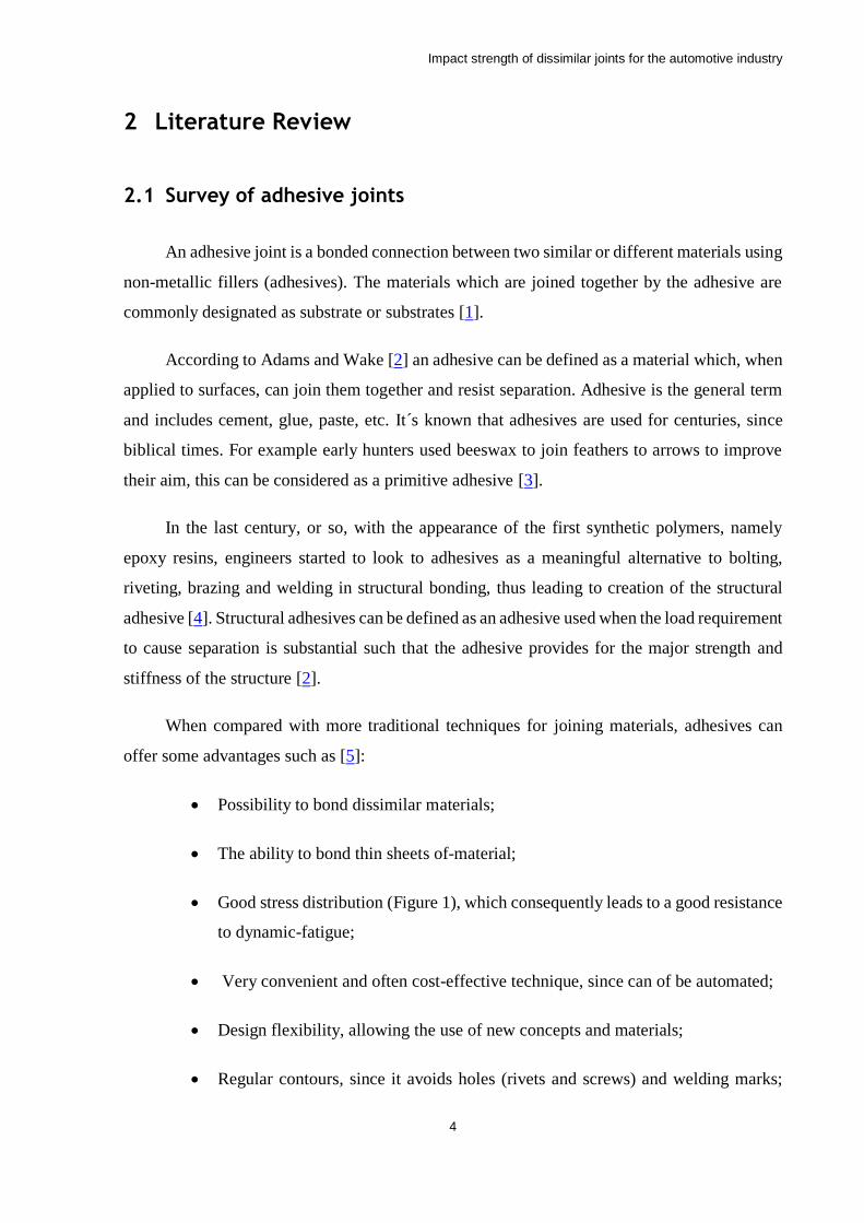
• Possibility to bond dissimilar materials;
• The ability to bond thin sheets of-material;
• Good stress distribution (Figure 1), which consequently leads to a good resistance
to dynamic-fatigue;
• Very convenient and often cost-effective technique, since can of be automated;
• Design flexibility, allowing the use of new concepts and materials;
• Regular contours, since it avoids holes (rivets and screws) and welding marks;
Impact strength of dissimilar joints for the automotive industry
5
Figure 1 - Comparison between riveted and adhesive bonded joints [1].
There are some disadvantages when it comes to adhesive joints [6]:
• Need to avoid peel and cleavage stresses (the biggest enemy of adhesive joints);
• Limited resistance to extreme environmental conditions like as high temperature
and humidity;
• Necessity of fastening tools to keep the parts in position since the bonding process
is not instantaneous;
• Requirement of extremely careful surface preparation, to avoid bad adhesion;
• Often requires high temperatures for curing (applied with oven, press, heater pads
etc.);
• Quality control is difficult to perform;
• Low maximum service temperature.
Impact strength of dissimilar joints for the automotive industry
6
2.1.1 Failure modes and joint design
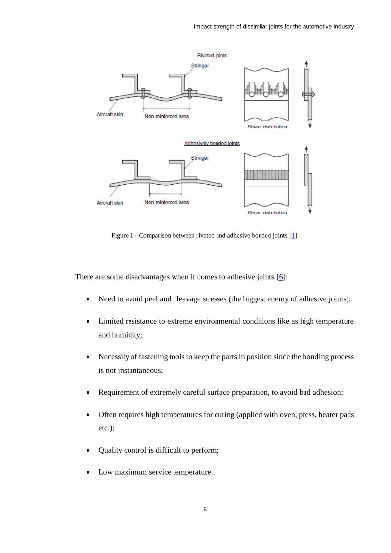
For bonded joints of metallic substrates, three different failure modes can occur in
adhesive joints (Figure 2) [1]. The first, cohesive failure in the adhesive, can be due to a few
reasons, like inadequate overlap length, thermal stresses or gross void defects. Sometimes,
when ductile substrates are used, this kind of failure can be caused by the onset of plastic
deformation on the substrates, introducing excessive peel stresses in the ends of the overlap
leading to cohesive failure in the adhesive. The second one, adhesive (interfacial) failure
appears in the interface between the adhesive and the adherend and is caused by poor surface
preparation. This can be the case if the adherend is contaminated with grease, rust, loose
particles or when the superficial energy of the adherend surface is much lower than that of the
adhesive. The third failure mode, cohesive failure in the adherend, occurs when the adherend
reaches its limit in terms of material strength. This is considered as an ideal case since it means
that the bonded region did not fail.
Figure 2 - Representation of failure modes: cohesion and adhesion [1].
Impact strength of dissimilar joints for the automotive industry
7
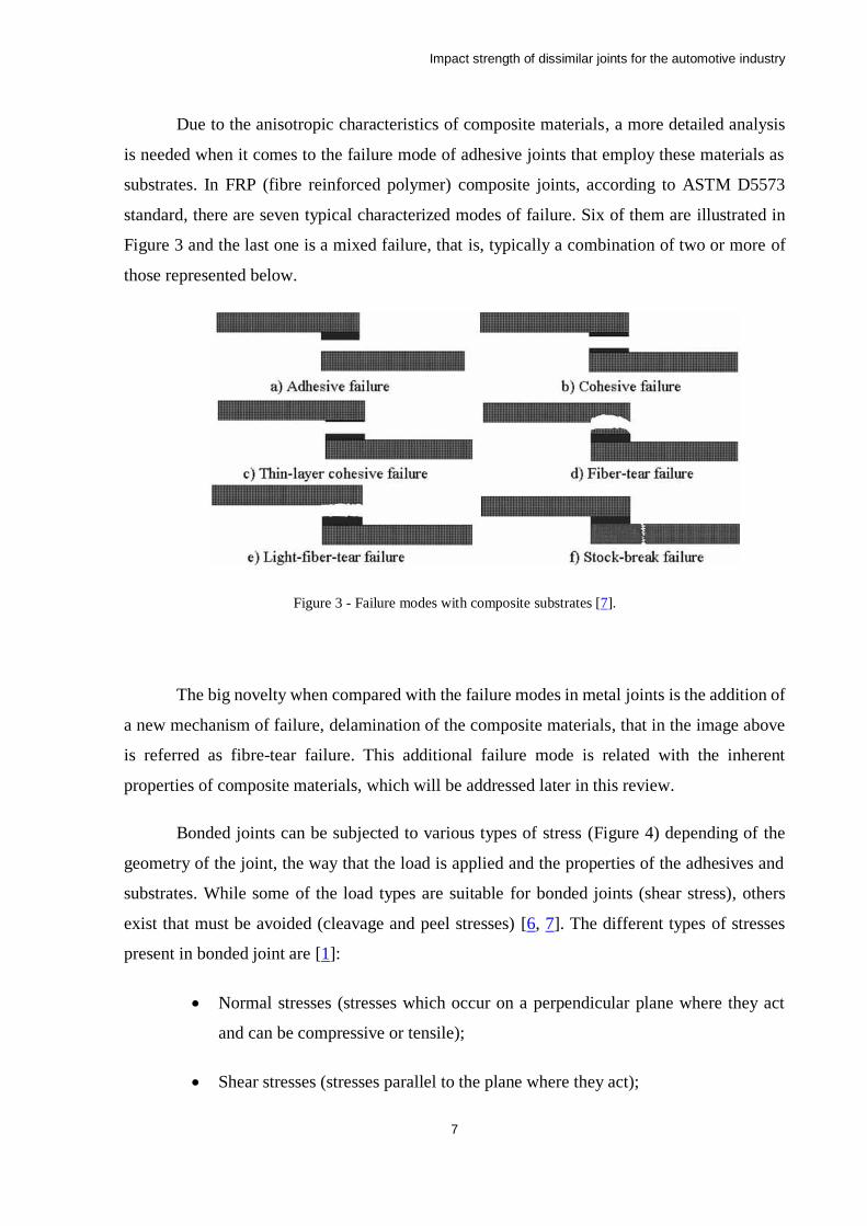
Due to the anisotropic characteristics of composite materials, a more detailed analysis
is needed when it comes to the failure mode of adhesive joints that employ these materials as
substrates. In FRP (fibre reinforced polymer) composite joints, according to ASTM D5573
standard, there are seven typical characterized modes of failure. Six of them are illustrated in
Figure 3 and the last one is a mixed failure, that is, typically a combination of two or more of
those represented below.
Figure 3 - Failure modes with composite substrates [7].
The big novelty when compared with the failure modes in metal joints is the addition of
a new mechanism of failure, delamination of the composite materials, that in the image above
is referred as fibre-tear failure. This additional failure mode is related with the inherent
properties of composite materials, which will be addressed later in this review.
Bonded joints can be subjected to various types of stress (Figure 4) depending of the
geometry of the joint, the way that the load is applied and the properties of the adhesives and
substrates. While some of the load types are suitable for bonded joints (shear stress), others
exist that must be avoided (cleavage and peel stresses) [6, 7]. The different types of stresses
present in bonded joint are [1]:
• Normal stresses (stresses which occur on a perpendicular plane where they act
and can be compressive or tensile);
• Shear stresses (stresses parallel to the plane where they act);

Impact strength of dissimilar joints for the automotive industry
8
• Peel stresses (stresses that appear on the edges of adhesive layer due to eccentric
loading);
• Cleavage (stresses originated from an offset tensile force or bending moment).
Figure 4 - Types of stresses in adhesive joints. (a) normal (or direct) stress, (b) shear stress, (c) cleavage, (d) peel
stress (adapted from [5]).
As mentioned before, geometry is a major factor when it comes to the types of stresses
present in a bonded joint, thus during the design stage, peel and cleavage stresses should be
minimized. Design changes on the substrates, the use of double lap joints (DLJ) and even the
use of local mechanical restraints are a few of the most common methods suggested to avoid
the most problematic situations. The most studied joint configurations in the literature are [7]:
• SLJs);
• Double-lap joints (DLJs);
• Scarf joints;
• Stepped lap joints.
Impact strength of dissimilar joints for the automotive industry
9
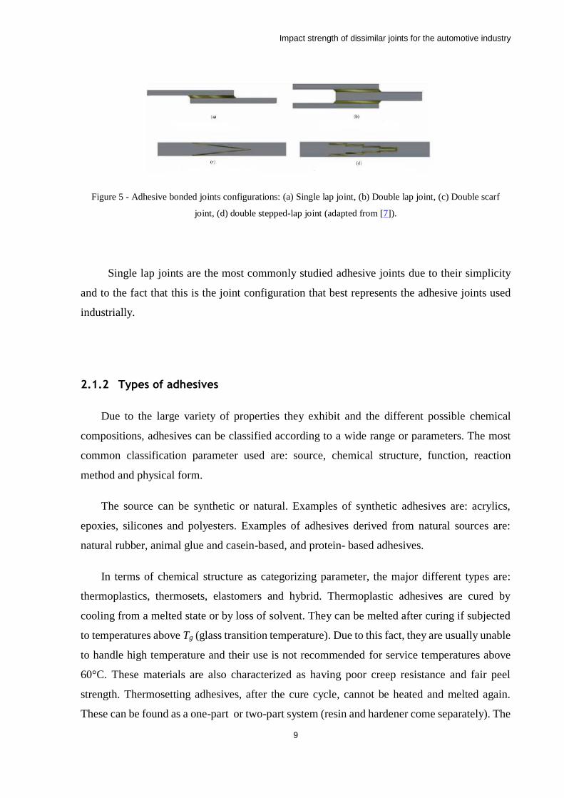
Figure 5 - Adhesive bonded joints configurations: (a) Single lap joint, (b) Double lap joint, (c) Double scarf
joint, (d) double stepped-lap joint (adapted from [7]).
Single lap joints are the most commonly studied adhesive joints due to their simplicity
and to the fact that this is the joint configuration that best represents the adhesive joints used
industrially.
2.1.2 Types of adhesives
Due to the large variety of properties they exhibit and the different possible chemical
compositions, adhesives can be classified according to a wide range or parameters. The most
common classification parameter used are: source, chemical structure, function, reaction
method and physical form.
The source can be synthetic or natural. Examples of synthetic adhesives are: acrylics,
epoxies, silicones and polyesters. Examples of adhesives derived from natural sources are:
natural rubber, animal glue and casein-based, and protein- based adhesives.
In terms of chemical structure as categorizing parameter, the major different types are:
thermoplastics, thermosets, elastomers and hybrid. Thermoplastic adhesives are cured by
cooling from a melted state or by loss of solvent. They can be melted after curing if subjected
to temperatures above Tg (glass transition temperature). Due to this fact, they are usually unable
to handle high temperature and their use is not recommended for service temperatures above
60°C. These materials are also characterized as having poor creep resistance and fair peel
strength. Thermosetting adhesives, after the cure cycle, cannot be heated and melted again.
These can be found as a one-part or two-part system (resin and hardener come separately). The
Impact strength of dissimilar joints for the automotive industry
10
one-part system usually requires high temperature to cure, and its shelf life is reduced. On the
other hand, the two-part systems cure at RT and have a longer shelf life, but the working
temperature is lower than the one-part adhesives. Elastomeric adhesives are not especially
strong but present a higher toughness, elongation and superior peel strength. Currently, many
adhesives on the market are hybrid formulations, which mix more than one type of adhesives
in one single product, offering a combination of the best properties from those adhesives. The
combination of different adhesives provides tougher and more flexible adhesive, with better
mechanical properties when subjected to impact [1].
Adhesives can also be classified regarding their function, and this is a very important
division, as it separates the adhesives between structural and non-structural. While non-
structural adhesives are most used as sealants, structural adhesives can withstand significant
loads. Examples of non-structural adhesives are: synthetic rubbers and polyesters. Examples
of structural adhesives are: epoxies, phenolics and polyurethanes.
The physical form of adhesives is another classification parameter. Adhesives are available
as liquids, pastes, films and powder. This is a very useful classification method to the industry,
mainly due to its implications in the joint manufacture process. For example, while liquid
adhesives have good gap filling capabilities they can flow out from the joint during
manufacture, something which does not occur with paste or film adhesives but the last struggle
to properly wet the surfaces.
The reaction method is also an important classification parameter with practical
importance, as it divides adhesives according to their cure method. Adhesives can cure by
chemical reaction, by loss of solvent, by loss of water or by cooling from melted state.
2.2 Adhesive joints in the automotive industry
The automotive industry has significantly increased the use of adhesives for joining
load-bearing components in an effort to reduce vehicle weight, improve fuel economy and
reduce emissions. However, the design process of a bonded structure can be complex, as the
properties of adhesives vary widely from brittle to highly deformable adhesives [1]. Adhesives
are viscoelastic, and their properties greatly depend on several factors such temperature,
Impact strength of dissimilar joints for the automotive industry
11
humidity and loading rate. While some design criteria consider these effects [5], there is still
limited information regarding the impact behaviour of bonded joints [8], especially when used
with composite substrates. Adhesive joints in the modern automotive industry can be found in
three main areas of application: the body shop, the paint shop and the trim shop. In the body
shop adhesives are used for hem flange bonding, anti-flutter bonding, and hybrid joining. The
use of adhesives in the paint shop is limited to a few minor applications, but in the assembly
lane/trim shop the use of adhesives is extensive, as most of the trim pieces are bonded to the
vehicle.
2.2.1 Structural adhesives used in the automotive industry
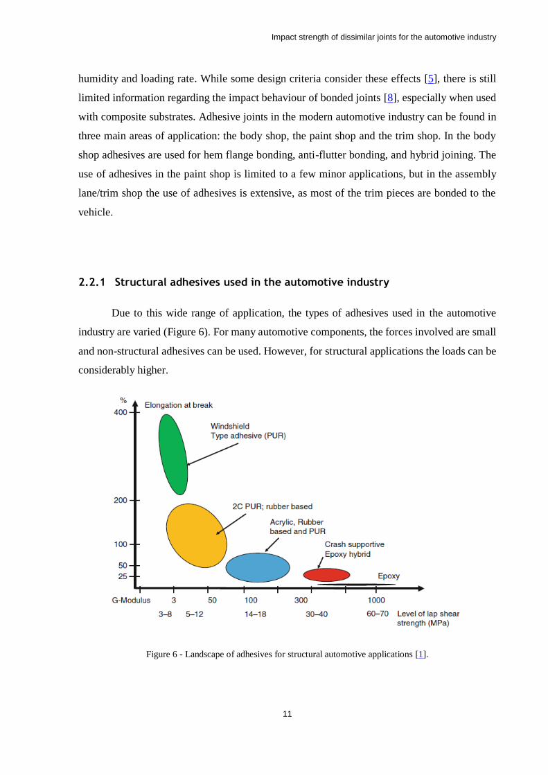
Due to this wide range of application, the types of adhesives used in the automotive
industry are varied (Figure 6). For many automotive components, the forces involved are small
and non-structural adhesives can be used. However, for structural applications the loads can be
considerably higher.
Figure 6 - Landscape of adhesives for structural automotive applications [1].
Impact strength of dissimilar joints for the automotive industry
12
The range of strength of structural adhesives used in automotive production is marked
at one end by windshield adhesives with rather low modulus and high elongation and at the
other end by very high strength epoxy adhesives. The top end of adhesives for automotive
bodies are crash-supportive epoxy-hybrid adhesives which have a somewhat lower shear
modulus than very high strength epoxies, but significantly higher elongation. The most
common adhesives used in this industry are epoxies, acrylics and polyurethanes. Table 1
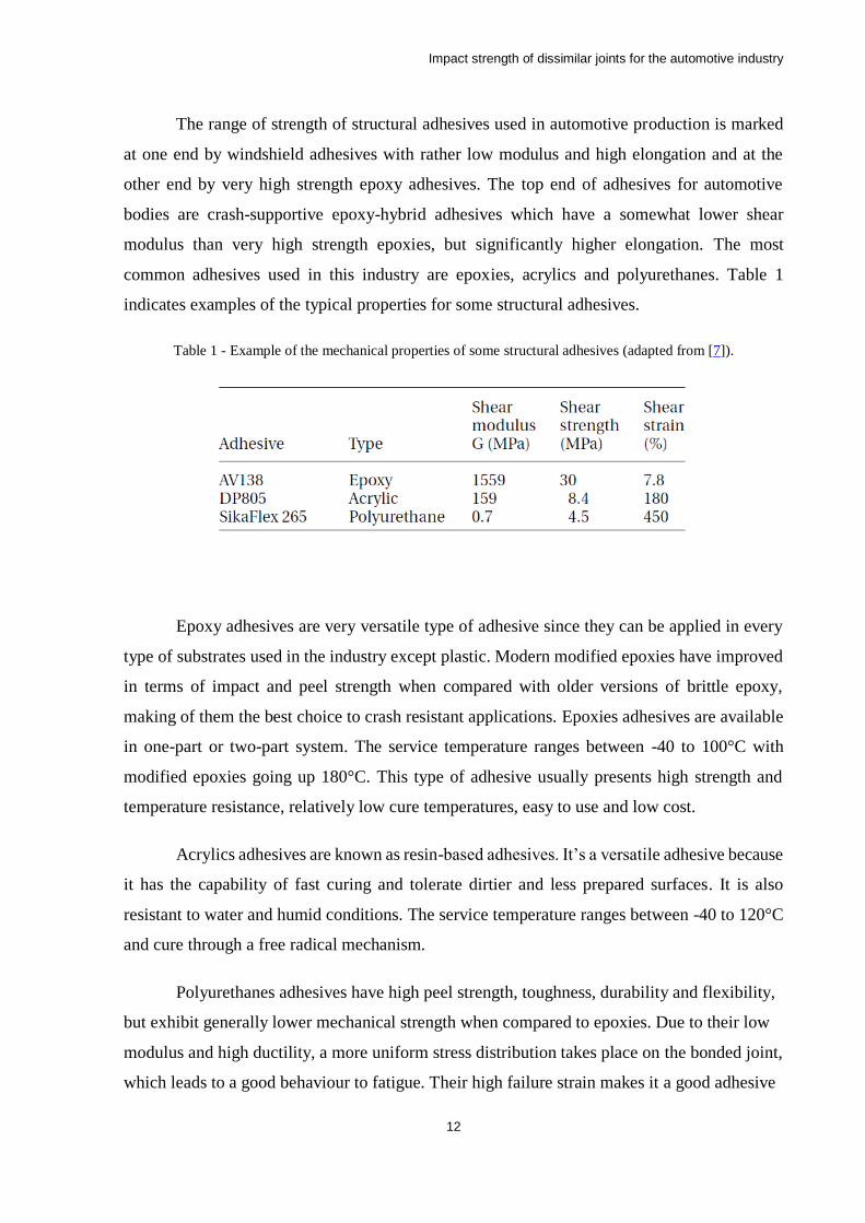
indicates examples of the typical properties for some structural adhesives.
Table 1 - Example of the mechanical properties of some structural adhesives (adapted from [7]).
Epoxy adhesives are very versatile type of adhesive since they can be applied in every
type of substrates used in the industry except plastic. Modern modified epoxies have improved
in terms of impact and peel strength when compared with older versions of brittle epoxy,
making of them the best choice to crash resistant applications. Epoxies adhesives are available
in one-part or two-part system. The service temperature ranges between -40 to 100°C with
modified epoxies going up 180°C. This type of adhesive usually presents high strength and
temperature resistance, relatively low cure temperatures, easy to use and low cost.
Acrylics adhesives are known as resin-based adhesives. It’s a versatile adhesive because
it has the capability of fast curing and tolerate dirtier and less prepared surfaces. It is also
resistant to water and humid conditions. The service temperature ranges between -40 to 120°C
and cure through a free radical mechanism.
Polyurethanes adhesives have high peel strength, toughness, durability and flexibility,
but exhibit generally lower mechanical strength when compared to epoxies. Due to their low
modulus and high ductility, a more uniform stress distribution takes place on the bonded joint,
which leads to a good behaviour to fatigue. Their high failure strain makes it a good adhesive
Impact strength of dissimilar joints for the automotive industry
13
for the absorption of impact. This type of adhesive is also available in one-part or two-part
system. The service temperature ranges between -200 to 80°C and they cure at RT.
2.2.2 Substrates used in the automotive industry
Although the majority of structural pieces used in the automotive industry are still made
from steel, it is also true that the aluminium and composite materials are gaining more and more
space in the industry. Vehicle bodies, that before were mainly made of steel, now increasingly
include assemblies made of aluminium. Additionally, the use of composite materials for
bonnets and other body panels is becoming more frequent [1]. Since various types of loads are
applied in different parts of a car, the use of different materials and geometries is necessary for
optimize weight reduction and overall structural stiffness. These two parameters are the focus
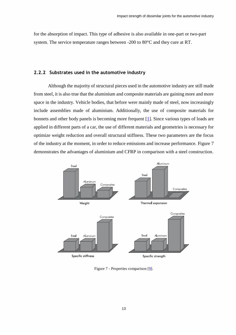
of the industry at the moment, in order to reduce emissions and increase performance. Figure 7
demonstrates the advantages of aluminium and CFRP in comparison with a steel construction.
Figure 7 - Properties comparison [9].
Impact strength of dissimilar joints for the automotive industry
14
2.2.2.1 Aluminium
The characteristic properties of aluminium, like high strength stiffness to weight ratio,
good formability, good corrosion resistance, and recycling potential make it the ideal candidate
to replace heavier materials (steel or copper) in the car to respond to the weight reduction
demand within the automotive industry. Despite aluminium density (2700 kg/m3) being about
one third of the steel (7600 kg/m3), the weight reduction when replacing steel by aluminium in
car manufacturing is around 50% because, to ensure strength and stiffness equivalent to that of
steel, the cross-sectional areas of aluminium elements need to be larger. The utilization of
aluminium in structural parts of vehicles is continually increasing as new alloys and design
solutions are developed. The use of aluminium alloys used in cars have increased more than
80% in total mass during the past 5 years. An increase from about 110 kg to approximately
between 250 to 340 kg was though to occur from 1996 to 2015 [10].
The 5000 and 6000 alloy series are particularly interesting for the automotive industry
since they allow the construction of the majority of the structure of a car body and because of
the improved bare metal corrosion when compare to steel [11]. The current requirements for
frontal impact can already be achieved using the AA6060 T6 alloy for construction of a space
frame-based vehicle.
Aluminium is also a good material for application in structures aiming at the absorption
of energy since it presents a mass-specific energy absorption capacity twice of that for mild
steels and is comparable with the latest high-strength steels (HSS steels). However, it is
important to mention that the behaviour of a given element during impact also strongly depends
on shape, wall thickness or the use of filling material [12, 13].
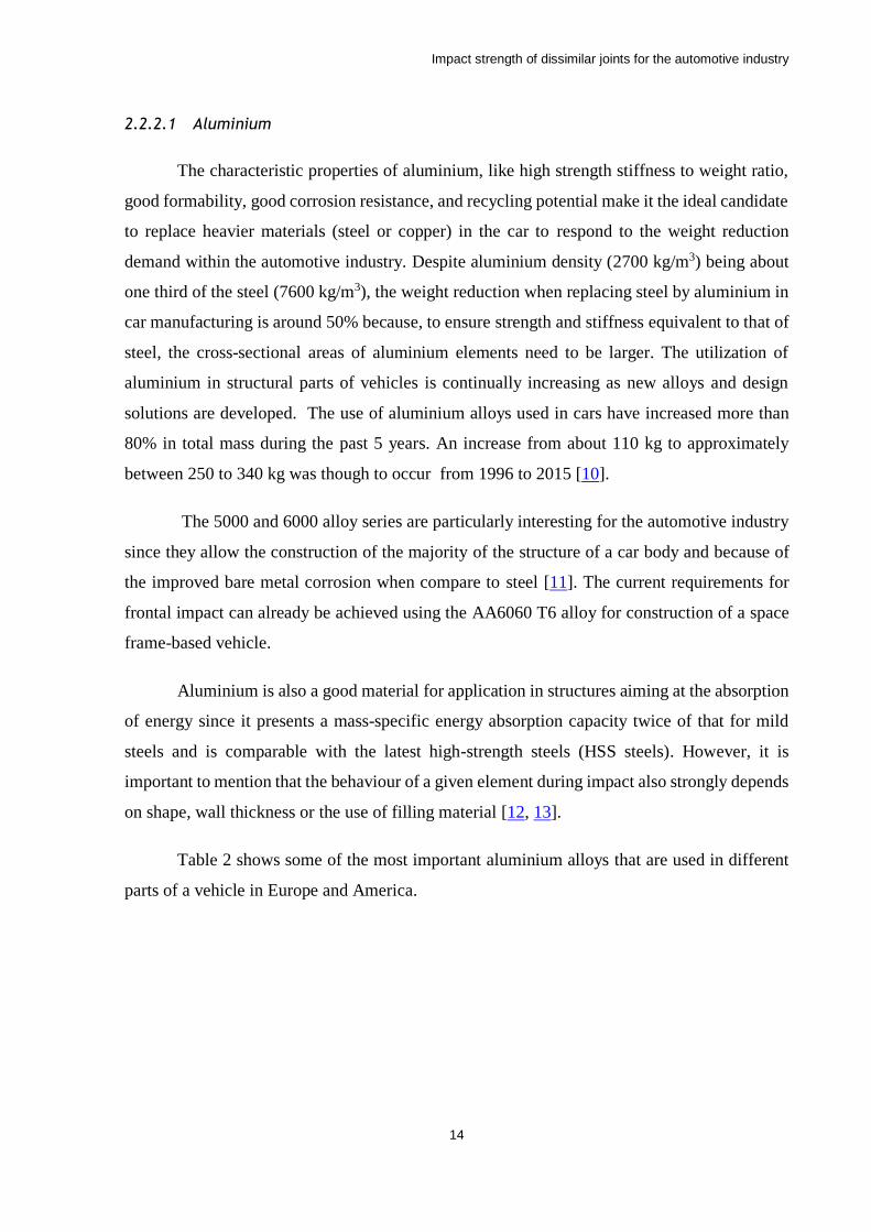
Table 2 shows some of the most important aluminium alloys that are used in different
parts of a vehicle in Europe and America.
Impact strength of dissimilar joints for the automotive industry
15
Table 2 - Comparison between aluminium alloys used in different car components in Europe versus North
America [11].
2.2.2.2 Composite materials
Composite materials, as the name indicates, are made of dissimilar constituents,
combined in order to obtain better properties than each constituent would have by their own.
The basic composite parameters provide the design flexibility enabling fibre architectural
design, adjustment of the fibre content, and the fibre packing ability. These types of materials
are increasingly used in automotive, aeronautical and aerospace industries because their high
specific strength. Composite materials also performed well under fatigue conditions. Other
good properties of these materials are: high specific stiffness, corrosion resistance and low
thermal expansion coefficient [14-16]
The basic constituents of a composite material are the load-carrying fibres, also known
as reinforcement, and the matrix, which in general is called the resin system during processing
phase and matrix in the consolidated phase, that is needed to keep the fibres together, in the
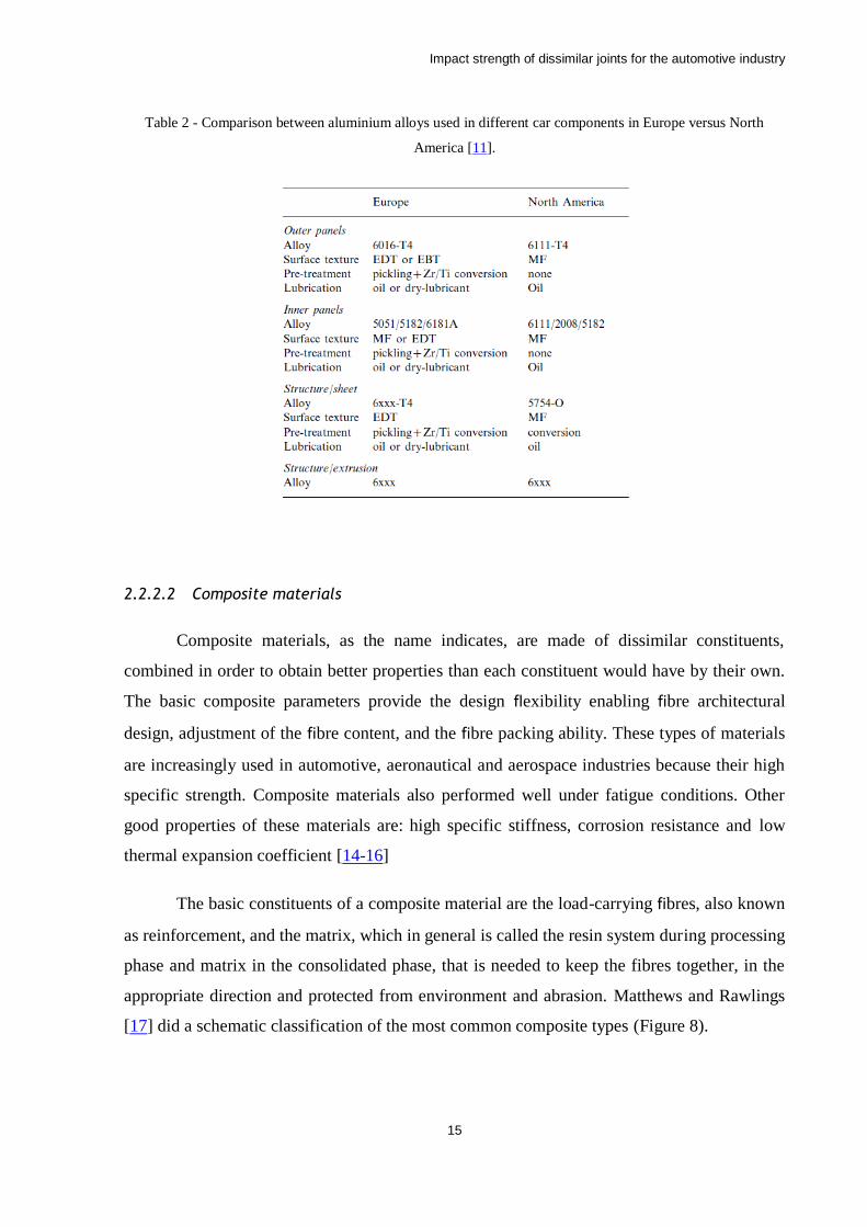
appropriate direction and protected from environment and abrasion. Matthews and Rawlings
[17] did a schematic classification of the most common composite types (Figure 8).
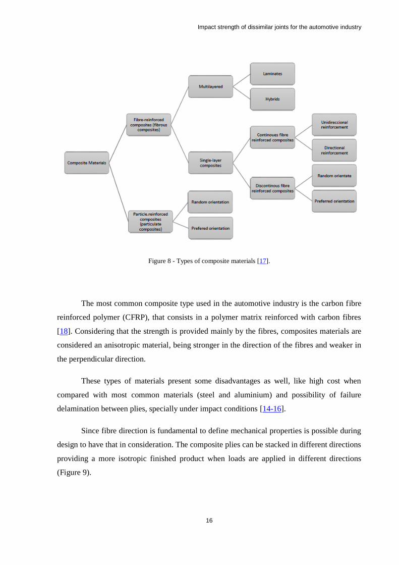
Impact strength of dissimilar joints for the automotive industry
16
Figure 8 - Types of composite materials [17].
The most common composite type used in the automotive industry is the carbon fibre
reinforced polymer (CFRP), that consists in a polymer matrix reinforced with carbon fibres
[18]. Considering that the strength is provided mainly by the fibres, composites materials are
considered an anisotropic material, being stronger in the direction of the fibres and weaker in
the perpendicular direction.
These types of materials present some disadvantages as well, like high cost when
compared with most common materials (steel and aluminium) and possibility of failure
delamination between plies, specially under impact conditions [14-16].
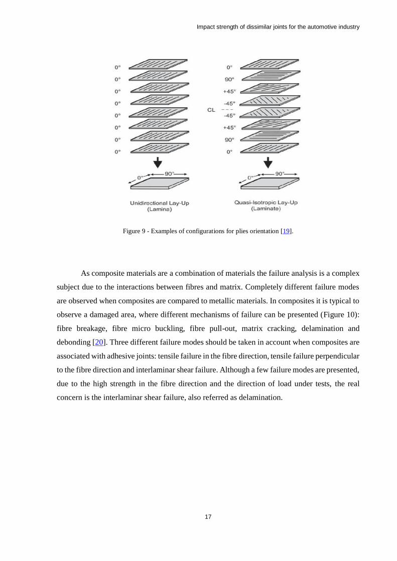
Since fibre direction is fundamental to define mechanical properties is possible during
design to have that in consideration. The composite plies can be stacked in different directions
providing a more isotropic finished product when loads are applied in different directions
(Figure 9).
Impact strength of dissimilar joints for the automotive industry
17
Figure 9 - Examples of configurations for plies orientation [19].
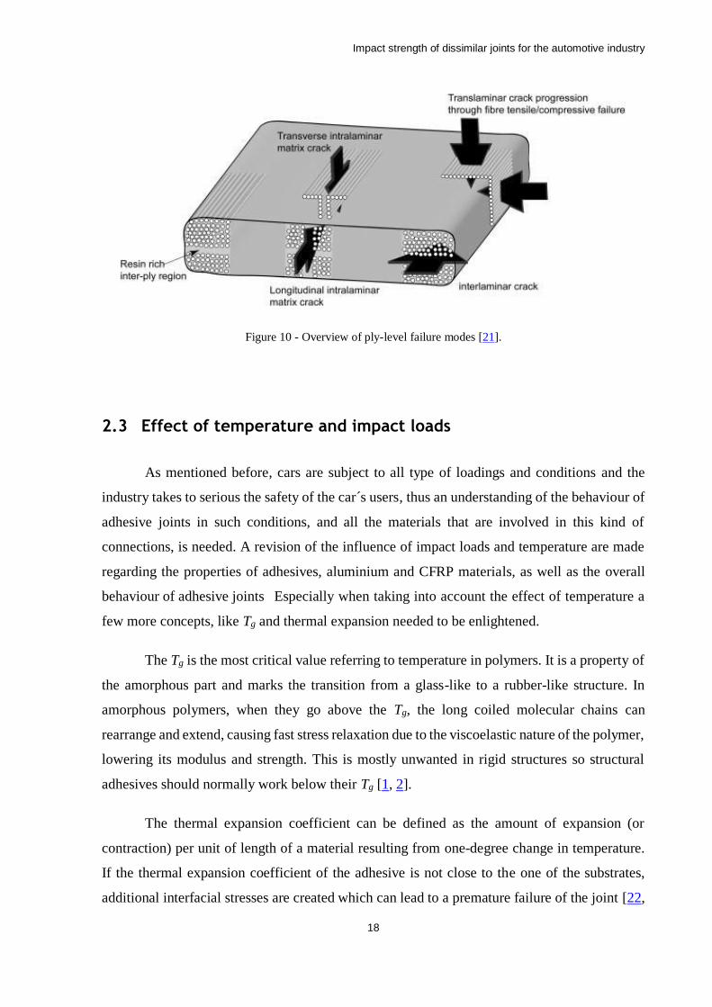
As composite materials are a combination of materials the failure analysis is a complex
subject due to the interactions between fibres and matrix. Completely different failure modes
are observed when composites are compared to metallic materials. In composites it is typical to
observe a damaged area, where different mechanisms of failure can be presented (Figure 10):
fibre breakage, fibre micro buckling, fibre pull-out, matrix cracking, delamination and
debonding [20]. Three different failure modes should be taken in account when composites are
associated with adhesive joints: tensile failure in the fibre direction, tensile failure perpendicular
to the fibre direction and interlaminar shear failure. Although a few failure modes are presented,
due to the high strength in the fibre direction and the direction of load under tests, the real
concern is the interlaminar shear failure, also referred as delamination.
Impact strength of dissimilar joints for the automotive industry
18
Figure 10 - Overview of ply-level failure modes [21].
2.3 Effect of temperature and impact loads
As mentioned before, cars are subject to all type of loadings and conditions and the
industry takes to serious the safety of the car´s users, thus an understanding of the behaviour of
adhesive joints in such conditions, and all the materials that are involved in this kind of
connections, is needed. A revision of the influence of impact loads and temperature are made
regarding the properties of adhesives, aluminium and CFRP materials, as well as the overall
behaviour of adhesive joints Especially when taking into account the effect of temperature a
few more concepts, like Tg and thermal expansion needed to be enlightened.
The Tg is the most critical value referring to temperature in polymers. It is a property of
the amorphous part and marks the transition from a glass-like to a rubber-like structure. In
amorphous polymers, when they go above the Tg, the long coiled molecular chains can
rearrange and extend, causing fast stress relaxation due to the viscoelastic nature of the polymer,
lowering its modulus and strength. This is mostly unwanted in rigid structures so structural
adhesives should normally work below their Tg [1, 2].
The thermal expansion coefficient can be defined as the amount of expansion (or
contraction) per unit of length of a material resulting from one-degree change in temperature.
If the thermal expansion coefficient of the adhesive is not close to the one of the substrates,
additional interfacial stresses are created which can lead to a premature failure of the joint [22,
Impact strength of dissimilar joints for the automotive industry
19
23]. Since this coefficient is generally higher for the adhesive when compared to the most
commonly used materials for the substrates, this is an important factor to consider when
creating an adhesively bonded structure. This expansion can be reduced by the addition of
mineral fillers [1].
Regarding impact loads analysis, the energy that adhesive joints are capable of
absorbing is an important factor, since, in case of accident it is important to guarantee the
structural integrity of the car structure, but, at the same time it is necessary that the structure
absorbs the energy of the collision, otherwise this energy will be transferred to the passengers
[24].
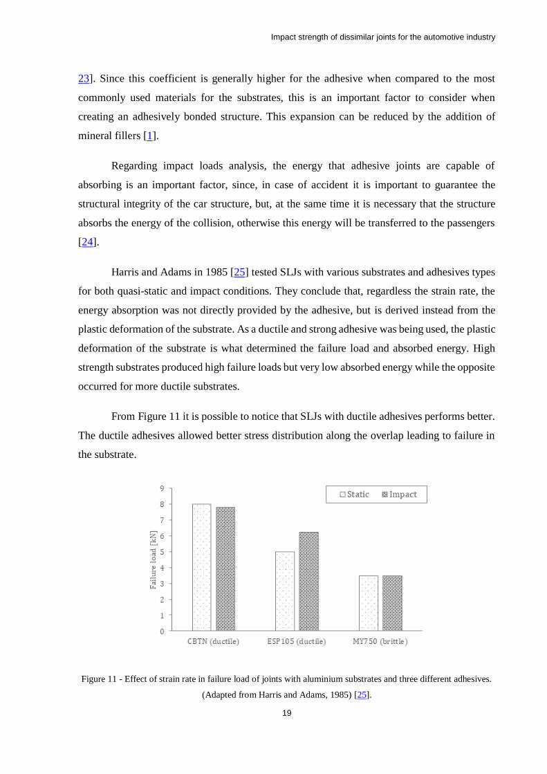
Harris and Adams in 1985 [25] tested SLJs with various substrates and adhesives types
for both quasi-static and impact conditions. They conclude that, regardless the strain rate, the
energy absorption was not directly provided by the adhesive, but is derived instead from the
plastic deformation of the substrate. As a ductile and strong adhesive was being used, the plastic
deformation of the substrate is what determined the failure load and absorbed energy. High
strength substrates produced high failure loads but very low absorbed energy while the opposite
occurred for more ductile substrates.
From Figure 11 it is possible to notice that SLJs with ductile adhesives performs better.
The ductile adhesives allowed better stress distribution along the overlap leading to failure in
the substrate.
Figure 11 - Effect of strain rate in failure load of joints with aluminium substrates and three different adhesives.
(Adapted from Harris and Adams, 1985) [25].
Impact strength of dissimilar joints for the automotive industry
20
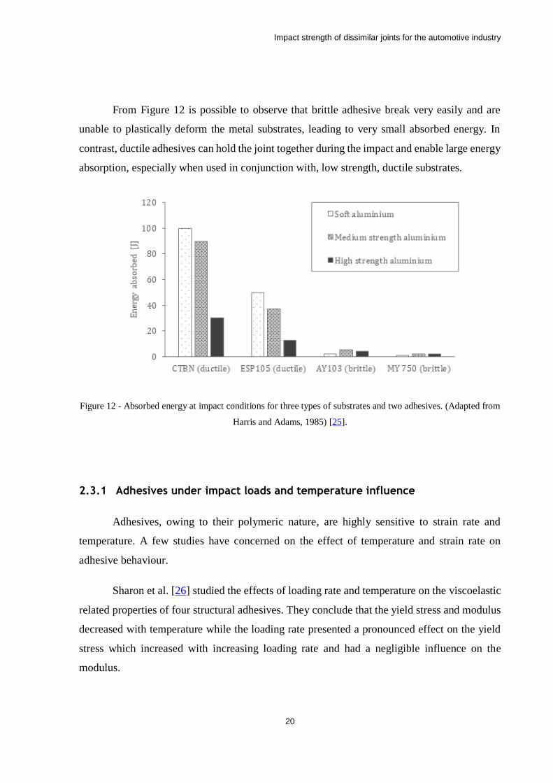
From Figure 12 is possible to observe that brittle adhesive break very easily and are
unable to plastically deform the metal substrates, leading to very small absorbed energy. In
contrast, ductile adhesives can hold the joint together during the impact and enable large energy
absorption, especially when used in conjunction with, low strength, ductile substrates.
Figure 12 - Absorbed energy at impact conditions for three types of substrates and two adhesives. (Adapted from
Harris and Adams, 1985) [25].
2.3.1 Adhesives under impact loads and temperature influence
Adhesives, owing to their polymeric nature, are highly sensitive to strain rate and
temperature. A few studies have concerned on the effect of temperature and strain rate on
adhesive behaviour.
Sharon et al. [26] studied the effects of loading rate and temperature on the viscoelastic
related properties of four structural adhesives. They conclude that the yield stress and modulus
decreased with temperature while the loading rate presented a pronounced effect on the yield
stress which increased with increasing loading rate and had a negligible influence on the
modulus.
Impact strength of dissimilar joints for the automotive industry
21
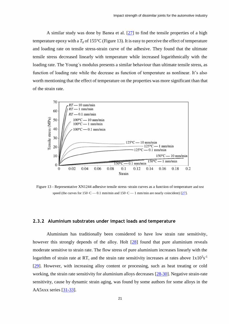
A similar study was done by Banea et al. [27] to find the tensile properties of a high
temperature epoxy with a Tg of 155°C (Figure 13). It is easy to perceive the effect of temperature
and loading rate on tensile stress-strain curve of the adhesive. They found that the ultimate
tensile stress decreased linearly with temperature while increased logarithmically with the
loading rate. The Young´s modulus presents a similar behaviour than ultimate tensile stress, as
function of loading rate while the decrease as function of temperature as nonlinear. It’s also
worth mentioning that the effect of temperature on the properties was more significant than that
of the strain rate.
Figure 13 - Representative XN1244 adhesive tensile stress–strain curves as a function of temperature and test
speed (the curves for 150◦C — 0.1 mm/min and 150◦C — 1 mm/min are nearly coincident) [27].
2.3.2 Aluminium substrates under impact loads and temperature
Aluminium has traditionally been considered to have low strain rate sensitivity,
however this strongly depends of the alloy. Holt [28] found that pure aluminium reveals
moderate sensitive to strain rate. The flow stress of pure aluminium increases linearly with the
logarithm of strain rate at RT, and the strain rate sensitivity increases at rates above 1x10³s-1
[29]. However, with increasing alloy content or processing, such as heat treating or cold
working, the strain rate sensitivity for aluminium alloys decreases [28-30]. Negative strain-rate
sensitivity, cause by dynamic strain aging, was found by some authors for some alloys in the
AA5xxx series [31-33].
Impact strength of dissimilar joints for the automotive industry
22
Oosterkamp et al. [34] did compression tests on AA6082 and AA7108 in tempers T6
and T79 at strain rates ranging from 0.1 to approximately 2000 s-1. At RT, they found a very
low, yet slightly positive, increase in flow stress with strain rate.
Smerd et al. [35] studied the stress-strain behaviour in tension of two non-tempered
aluminium alloys for a four strain rates from 3.3x10⁻³ s-1 to 1500 s-1 and for four temperatures
(23, 50, 150 and 300°C). The results show that strain rate sensitivity to was low for both alloys
at al temperatures tested.
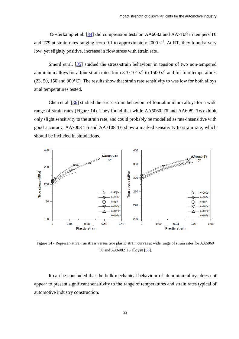
Chen et al. [36] studied the stress-strain behaviour of four aluminium alloys for a wide
range of strain rates (Figure 14). They found that while AA6060 T6 and AA6082 T6 exhibit
only slight sensitivity to the strain rate, and could probably be modelled as rate-insensitive with
good accuracy, AA7003 T6 and AA7108 T6 show a marked sensitivity to strain rate, which
should be included in simulations.
Figure 14 - Representative true stress versus true plastic strain curves at wide range of strain rates for AA6060
T6 and AA6082 T6 alloys0 [36].
It can be concluded that the bulk mechanical behaviour of aluminium alloys does not
appear to present significant sensitivity to the range of temperatures and strain rates typical of
automotive industry construction.
Impact strength of dissimilar joints for the automotive industry
23
2.3.3 CFRP substrates under impact loads and temperature
Considering that composite materials are anisotropic and composed by two constituents,
the behaviour analysis as a function of temperature and strain rate isn´t straight forward. While
the carbon reinforcements are highly insensitive to temperature variation and loading rate, the
matrix is made of a polymer material, the same family material that adhesives are made of.
From what was mentioned a above regarding adhesives, it is expected that temperature
and strain rate have influence in the CFRP properties. This topic was investigated by several
authors.
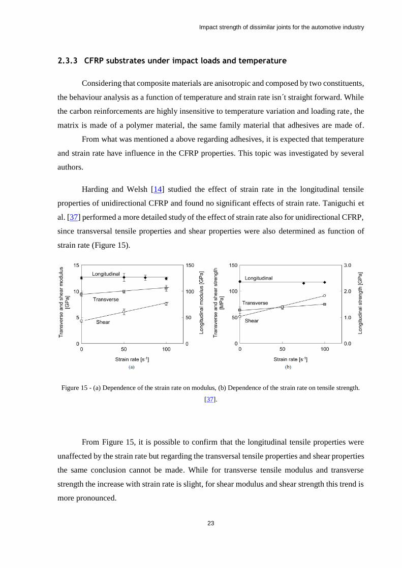
Harding and Welsh [14] studied the effect of strain rate in the longitudinal tensile
properties of unidirectional CFRP and found no significant effects of strain rate. Taniguchi et
al. [37] performed a more detailed study of the effect of strain rate also for unidirectional CFRP,
since transversal tensile properties and shear properties were also determined as function of
strain rate (Figure 15).
Figure 15 - (a) Dependence of the strain rate on modulus, (b) Dependence of the strain rate on tensile strength.
[37].
From Figure 15, it is possible to confirm that the longitudinal tensile properties were
unaffected by the strain rate but regarding the transversal tensile properties and shear properties
the same conclusion cannot be made. While for transverse tensile modulus and transverse
strength the increase with strain rate is slight, for shear modulus and shear strength this trend is
more pronounced.
Impact strength of dissimilar joints for the automotive industry
24
Hou and Ruiz [38] also concluded in their study that properties that are dominated by
the matrix like compression strength, Poisson’s ratio, in-plane shear modulus, shear modulus
and shear strength are strain rate dependent. The properties dominated by the fibres like tensile
modulus and strength are virtually rate independent.
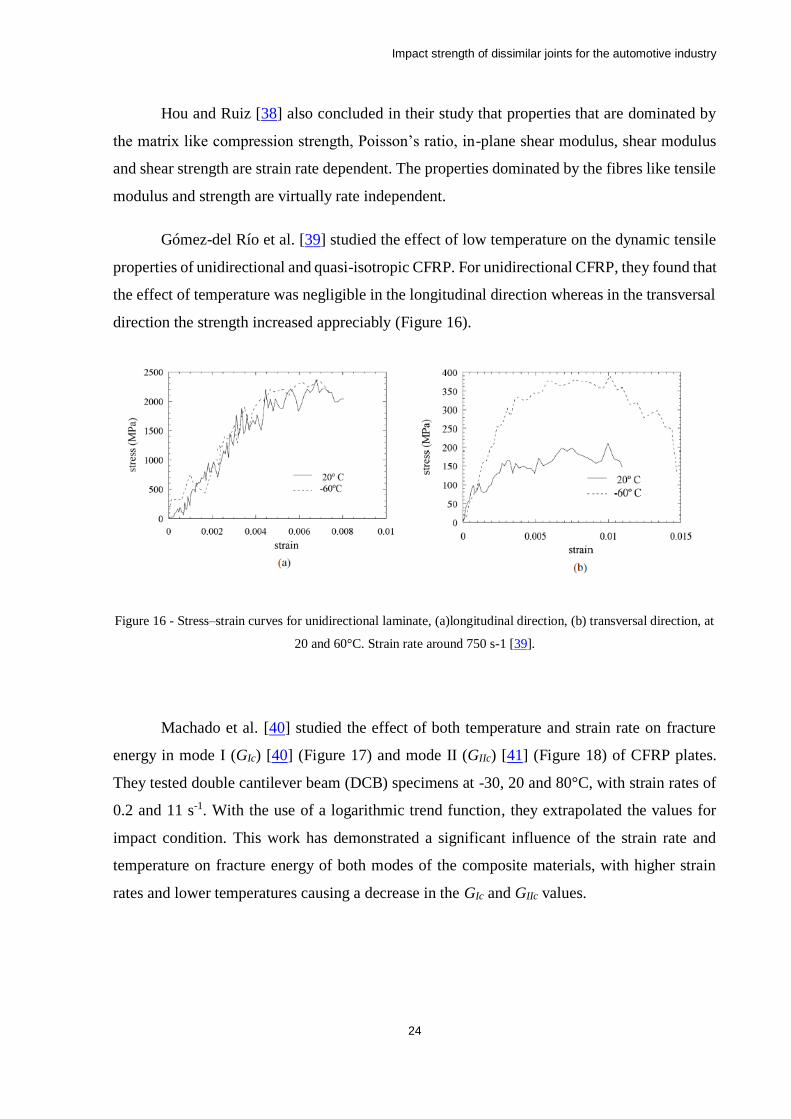
Gómez-del Río et al. [39] studied the effect of low temperature on the dynamic tensile
properties of unidirectional and quasi-isotropic CFRP. For unidirectional CFRP, they found that
the effect of temperature was negligible in the longitudinal direction whereas in the transversal
direction the strength increased appreciably (Figure 16).
Figure 16 - Stress–strain curves for unidirectional laminate, (a)longitudinal direction, (b) transversal direction, at
20 and 60°C. Strain rate around 750 s-1 [39].
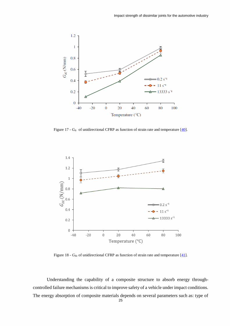
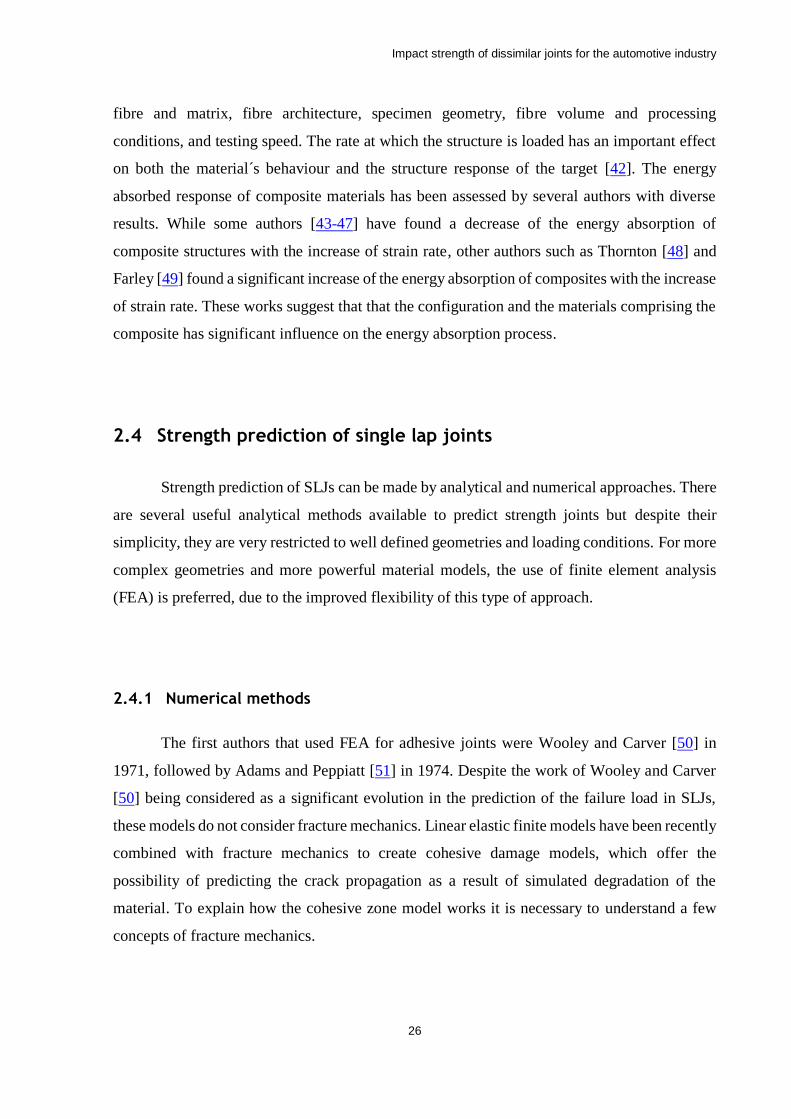
Machado et al. [40] studied the effect of both temperature and strain rate on fracture
energy in mode I (GIc) [40] (Figure 17) and mode II (GIIc) [41] (Figure 18) of CFRP plates.
They tested double cantilever beam (DCB) specimens at -30, 20 and 80°C, with strain rates of
0.2 and 11 s-1. With the use of a logarithmic trend function, they extrapolated the values for
impact condition. This work has demonstrated a significant influence of the strain rate and
temperature on fracture energy of both modes of the composite materials, with higher strain
rates and lower temperatures causing a decrease in the GIc and GIIc values.
Impact strength of dissimilar joints for the automotive industry
25
Figure 17 - GIc of unidirectional CFRP as function of strain rate and temperature [40].
Figure 18 - GIIc of unidirectional CFRP as function of strain rate and temperature [41].
Understanding the capability of a composite structure to absorb energy through-
controlled failure mechanisms is critical to improve safety of a vehicle under impact conditions.
The energy absorption of composite materials depends on several parameters such as: type of
Impact strength of dissimilar joints for the automotive industry
26
fibre and matrix, fibre architecture, specimen geometry, fibre volume and processing
conditions, and testing speed. The rate at which the structure is loaded has an important effect
on both the material´s behaviour and the structure response of the target [42]. The energy
absorbed response of composite materials has been assessed by several authors with diverse
results. While some authors [43-47] have found a decrease of the energy absorption of
composite structures with the increase of strain rate, other authors such as Thornton [48] and
Farley [49] found a significant increase of the energy absorption of composites with the increase
of strain rate. These works suggest that that the configuration and the materials comprising the
composite has significant influence on the energy absorption process.
2.4 Strength prediction of single lap joints
Strength prediction of SLJs can be made by analytical and numerical approaches. There
are several useful analytical methods available to predict strength joints but despite their
simplicity, they are very restricted to well defined geometries and loading conditions. For more
complex geometries and more powerful material models, the use of finite element analysis
(FEA) is preferred, due to the improved flexibility of this type of approach.
2.4.1 Numerical methods
The first authors that used FEA for adhesive joints were Wooley and Carver [50] in
1971, followed by Adams and Peppiatt [51] in 1974. Despite the work of Wooley and Carver
[50] being considered as a significant evolution in the prediction of the failure load in SLJs,
these models do not consider fracture mechanics. Linear elastic finite models have been recently
combined with fracture mechanics to create cohesive damage models, which offer the
possibility of predicting the crack propagation as a result of simulated degradation of the
material. To explain how the cohesive zone model works it is necessary to understand a few
concepts of fracture mechanics.
Impact strength of dissimilar joints for the automotive industry
27
2.4.1.1 – Fracture critical energy
In fracture mechanics it is assumed that materials in a structure are not necessarily a
continuum medium, this means that defects can occur in the manufacturing process, for
example, and it is essential to understand how these defects can evolve during the life time of
the structure, if it leads to a catastrophic failure or if can safely being used despite a possible
stable propagation.
The basic principles of fracture mechanics, mainly due to Griffith [52], state that all
bodies have a defect distribution and fracture occurs from the critical one. There are two
different criteria that allow to develop the principle above, a stress concentration factor-based
criterion and energetic criterion. Griffith established that an internal defect will propagate when
the available energy at the tip of the defect (G - release rate energy), due to the loading, equals
the energy needed for crack propagation (Gc - critical release rate energy), that is a material
property. Kinloch [5] refers that is advantageous to use the energy criterion instead of the factor
criterion, in what concerns adhesive joints.
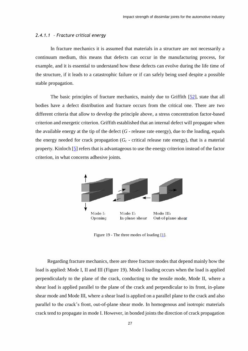
Figure 19 - The three modes of loading [1].
Regarding fracture mechanics, there are three fracture modes that depend mainly how the
load is applied: Mode I, II and III (Figure 19). Mode I loading occurs when the load is applied
perpendicularly to the plane of the crack, conducting to the tensile mode, Mode II, where a
shear load is applied parallel to the plane of the crack and perpendicular to its front, in-plane
shear mode and Mode III, where a shear load is applied on a parallel plane to the crack and also
parallel to the crack’s front, out-of-plane shear mode. In homogenous and isotropic materials
crack tend to propagate in mode I. However, in bonded joints the direction of crack propagation
Impact strength of dissimilar joints for the automotive industry
28
is restricted by the substrates causing, in most of the cases, a mixed-mode propagation in mode
I+II.
For each loading mode there are a few tests to determine the fracture energy. For mode I, Double
Cantilever Beam (DCB) and Tapered Double Cantilever Beam (TDCB), while End-Notched
Flexure (ENF), End Loaded Split (ELS) and Four-Point Notched Flexure (4ENF) are used for
mode II [1].
2.4.1.2 - Cohesive damage model
The necessity to make a bridge between stress analysis criteria and classical fracture
mechanics led to the creation of a computational tool called the Cohesive Zone Model (CZM).
The combination of the stress criteria with the fracture mechanics data made possible to
determine the crack initiation and growth. The CZM was first introduced by Barenblatt [53]
based on the Griffith´s theory of fracture, however the first researcher that applied it to the
computational frameworks of FE modelling was Hillerborg et al. [54], who established the
relation between traction and the crack opening displacement, and consequently the law of
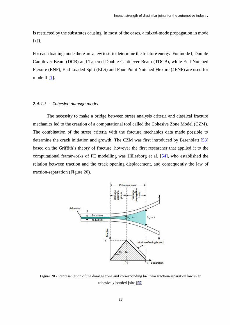
traction-separation (Figure 20).
Figure 20 - Representation of the damage zone and corresponding bi-linear traction-separation law in an
adhesively bonded joint [55].
Impact strength of dissimilar joints for the automotive industry
29
The traction-separation law (Figure 21) describes the material behaviour in two distinct
phases, the first related to the damage initiation phase, that can be delimited by the elastic
behaviour and its limit and another related to the damage propagation phase. Traction-
separation laws can present various shapes like triangular, the most common, trapezoidal and
exponential, these shapes are related with the plastic behaviour of the material. Although
trapezoidal law is mainly used on ductile materials, and the triangular law is used on brittle and
composite materials, some authors use triangular law for ductile materials as it is the most
common.
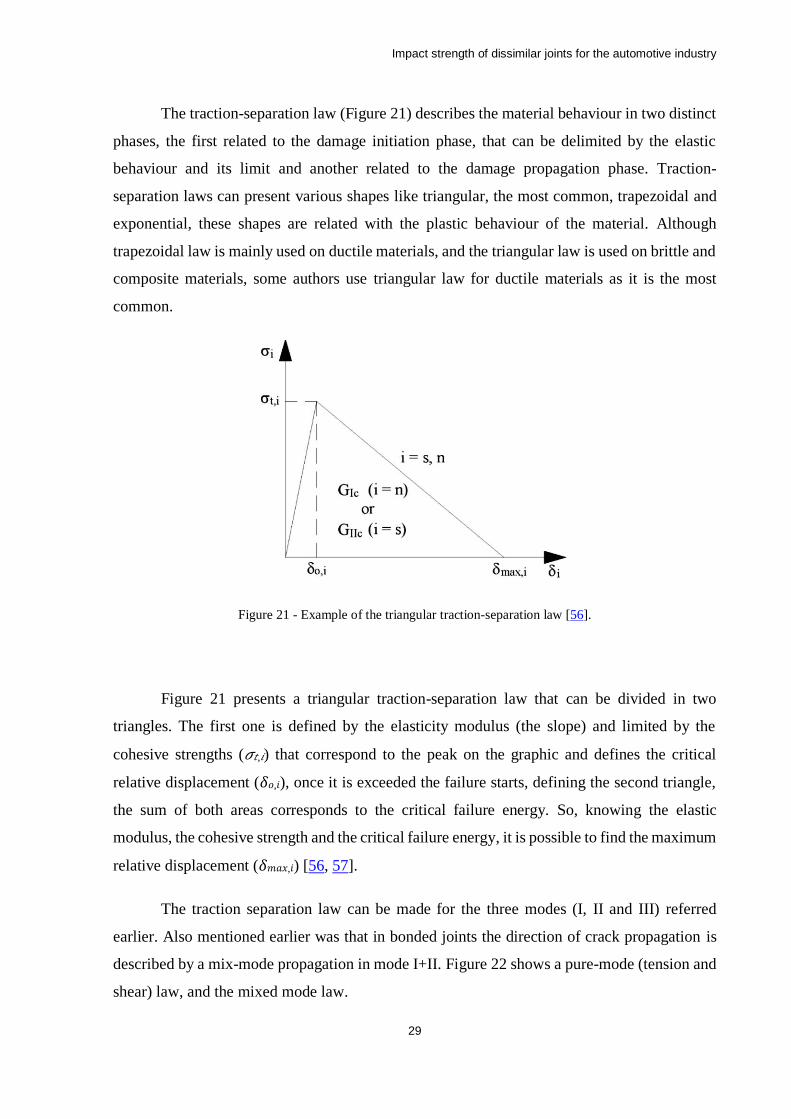
Figure 21 - Example of the triangular traction-separation law [56].
Figure 21 presents a triangular traction-separation law that can be divided in two
triangles. The first one is defined by the elasticity modulus (the slope) and limited by the
cohesive strengths (𝜎𝑡,𝑖) that correspond to the peak on the graphic and defines the critical
relative displacement (𝛿𝑜,𝑖), once it is exceeded the failure starts, defining the second triangle,
the sum of both areas corresponds to the critical failure energy. So, knowing the elastic
modulus, the cohesive strength and the critical failure energy, it is possible to find the maximum
relative displacement (𝛿𝑚𝑎𝑥,𝑖) [56, 57].
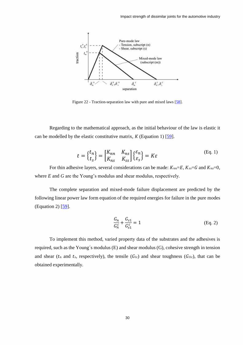
The traction separation law can be made for the three modes (I, II and III) referred
earlier. Also mentioned earlier was that in bonded joints the direction of crack propagation is
described by a mix-mode propagation in mode I+II. Figure 22 shows a pure-mode (tension and
shear) law, and the mixed mode law.
Impact strength of dissimilar joints for the automotive industry
30
Figure 22 - Traction-separation law with pure and mixed laws [58].
Regarding to the mathematical approach, as the initial behaviour of the law is elastic it
can be modelled by the elastic constitutive matrix, 𝐾 (Equation 1) [59].
𝑡 = {𝑡𝑛
𝑡𝑠} = [
𝐾𝑛𝑛 𝐾𝑛𝑠
𝐾𝑛𝑠 𝐾𝑠𝑠] {
휀𝑛
휀𝑠} = 𝐾휀
(Eq. 1)
For thin adhesive layers, several considerations can be made: 𝐾𝑛𝑛=𝐸, 𝐾𝑠𝑠=𝐺 and 𝐾𝑛𝑠=0,
where E and G are the Young’s modulus and shear modulus, respectively.
The complete separation and mixed-mode failure displacement are predicted by the
following linear power law form equation of the required energies for failure in the pure modes
(Equation 2) [59].
𝐺𝑛
𝐺𝑛𝑐 +
𝐺𝑠1
𝐺𝑠1𝑐 = 1 (Eq. 2)
To implement this method, varied property data of the substrates and the adhesives is
required, such as the Young´s modulus (E) and shear modulus (G), cohesive strength in tension
and shear (𝑡𝑛 and 𝑡𝑠, respectively), the tensile (𝐺𝐼c) and shear toughness (𝐺𝐼𝐼c), that can be
obtained experimentally.
Impact strength of dissimilar joints for the automotive industry
31
3 Experimental details
3.1 Material selection
One adhesive was selected for this study, a ductile, one-component, epoxy based
adhesive, Nagase-ChemteX XNR6852 E-3, supplied by Nagase ChemteX® (Osaka, Japan)
(Table 3). This adhesive was selected because is a crash resistant adhesive and has been study
by the adhesive group in previous works. The CFRP selected for this specific lay-up and fibre
orientation was due the existence of data from previous works performed by the adhesive group.
Table 3 - General properties of the crash-resistant adhesive used (Nagase-ChemteX XNR6852 E-3).
Three different materials for the substrates were used in this study, two aluminium
alloys (AA5754 H22 and AA6060 T6) and a composite material (CFRP). The aluminium alloys
were selected as a request from Aston Martin Lagonda®, aiming to evaluate the behaviour of
adhesive joints with these alloys as substrates, as well with CFRP, under conditions typical of
the automotive industry (Table 4), that is, under quasi-static and impact conditions for a range
of temperature between -30 to 80°C. These types of materials are currently being used in the
latest models commercialized, as well as prototypes being developed by this car manufacturer.
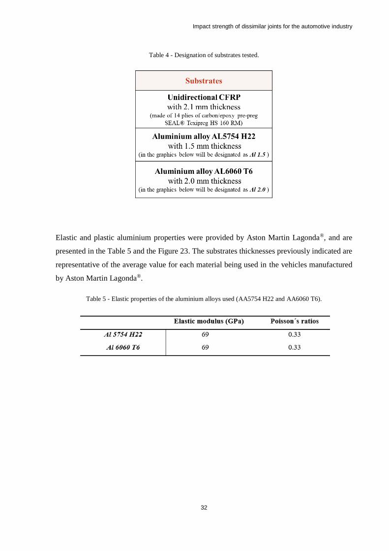
Impact strength of dissimilar joints for the automotive industry
32
Table 4 - Designation of substrates tested.
Elastic and plastic aluminium properties were provided by Aston Martin Lagonda®, and are
presented in the Table 5 and the Figure 23. The substrates thicknesses previously indicated are
representative of the average value for each material being used in the vehicles manufactured
by Aston Martin Lagonda®.
Table 5 - Elastic properties of the aluminium alloys used (AA5754 H22 and AA6060 T6).
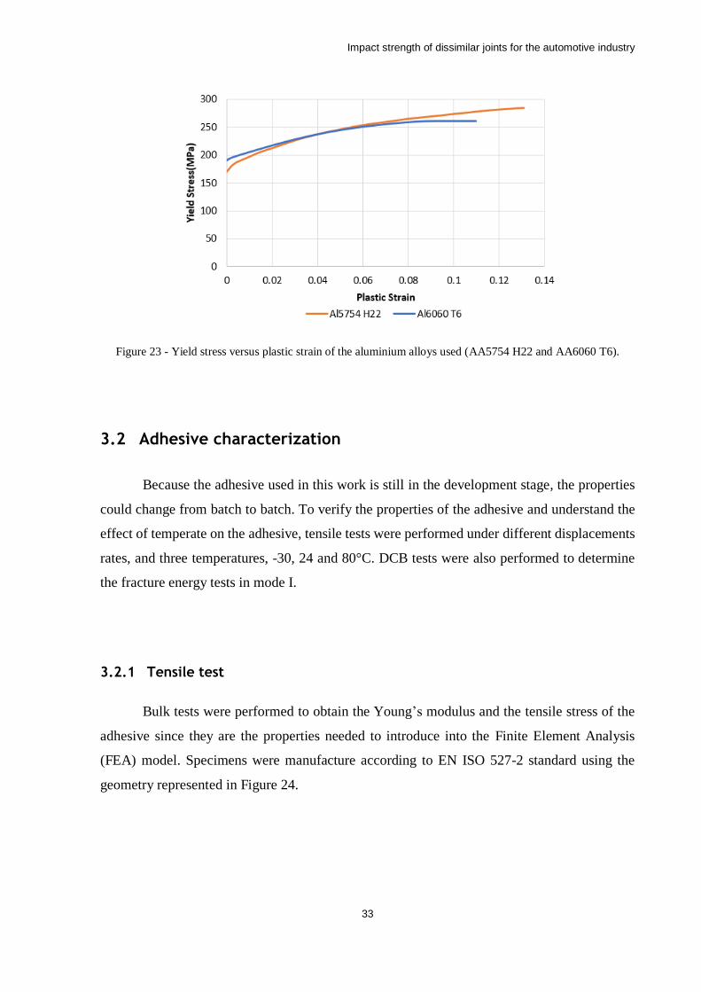
Impact strength of dissimilar joints for the automotive industry
33
Figure 23 - Yield stress versus plastic strain of the aluminium alloys used (AA5754 H22 and AA6060 T6).
3.2 Adhesive characterization
Because the adhesive used in this work is still in the development stage, the properties
could change from batch to batch. To verify the properties of the adhesive and understand the
effect of temperate on the adhesive, tensile tests were performed under different displacements
rates, and three temperatures, -30, 24 and 80°C. DCB tests were also performed to determine
the fracture energy tests in mode I.
3.2.1 Tensile test
Bulk tests were performed to obtain the Young’s modulus and the tensile stress of the
adhesive since they are the properties needed to introduce into the Finite Element Analysis
(FEA) model. Specimens were manufacture according to EN ISO 527-2 standard using the
geometry represented in Figure 24.
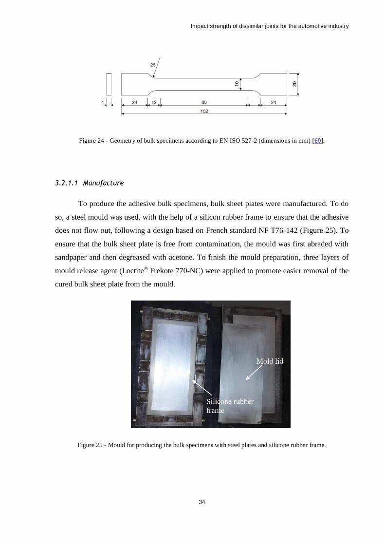
Impact strength of dissimilar joints for the automotive industry
34
Figure 24 - Geometry of bulk specimens according to EN ISO 527-2 (dimensions in mm) [60].
3.2.1.1 Manufacture
To produce the adhesive bulk specimens, bulk sheet plates were manufactured. To do
so, a steel mould was used, with the help of a silicon rubber frame to ensure that the adhesive
does not flow out, following a design based on French standard NF T76-142 (Figure 25). To
ensure that the bulk sheet plate is free from contamination, the mould was first abraded with
sandpaper and then degreased with acetone. To finish the mould preparation, three layers of
mould release agent (Loctite® Frekote 770-NC) were applied to promote easier removal of the
cured bulk sheet plate from the mould.
Figure 25 - Mould for producing the bulk specimens with steel plates and silicone rubber frame.
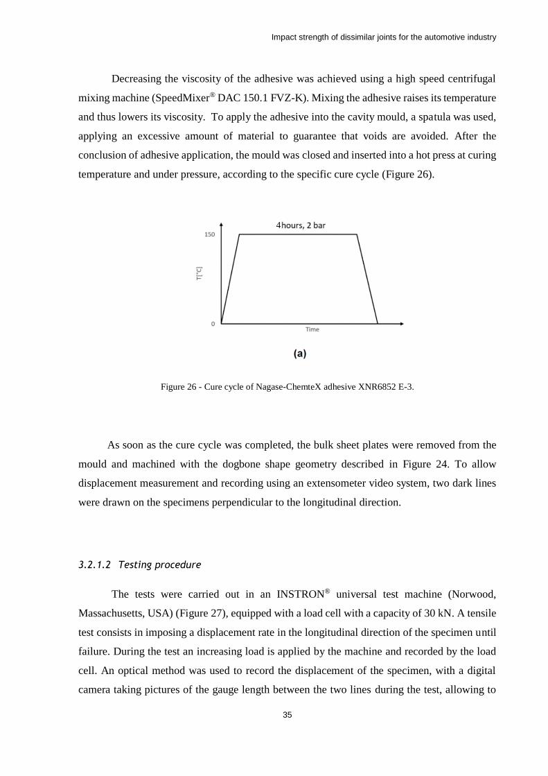
Impact strength of dissimilar joints for the automotive industry
35
Decreasing the viscosity of the adhesive was achieved using a high speed centrifugal
mixing machine (SpeedMixer® DAC 150.1 FVZ-K). Mixing the adhesive raises its temperature
and thus lowers its viscosity. To apply the adhesive into the cavity mould, a spatula was used,
applying an excessive amount of material to guarantee that voids are avoided. After the
conclusion of adhesive application, the mould was closed and inserted into a hot press at curing
temperature and under pressure, according to the specific cure cycle (Figure 26).
Figure 26 - Cure cycle of Nagase-ChemteX adhesive XNR6852 E-3.
As soon as the cure cycle was completed, the bulk sheet plates were removed from the
mould and machined with the dogbone shape geometry described in Figure 24. To allow
displacement measurement and recording using an extensometer video system, two dark lines
were drawn on the specimens perpendicular to the longitudinal direction.
3.2.1.2 Testing procedure
The tests were carried out in an INSTRON® universal test machine (Norwood,
Massachusetts, USA) (Figure 27), equipped with a load cell with a capacity of 30 kN. A tensile
test consists in imposing a displacement rate in the longitudinal direction of the specimen until
failure. During the test an increasing load is applied by the machine and recorded by the load
cell. An optical method was used to record the displacement of the specimen, with a digital
camera taking pictures of the gauge length between the two lines during the test, allowing to
4

Impact strength of dissimilar joints for the automotive industry
36
record all the stages until failure. An image processing and analysing software was used to
obtain the strain for each specimen. The width and thickness of each specimen were measured
in order to calculate the stress of each strain stage.
Figure 27 - INSTRON® universal test machine.
At least four specimens of each adhesive for each condition were tested. The strain rate
conditions were, 0.004 s-1, equivalent to a displacement rate of 1 mm/min, and 0.42 s-1, which
is equivalent to a displacement rate of 100 mm/min. For each strain rate tests were performed
at three different temperatures (-30, 24 and 80°C).
The conversion of machine cross-head displacement to strain rate was conducted,
resorting to Equation 3 to correctly estimate the effect of the testing speed, since it is more
accurate to use the actual strain rate of the tested material.
휀̇(𝑡) = (
𝐿(𝑡) − 𝐿0
𝐿0) =
𝑣(𝑡)
𝐿0 (Eq. 3)
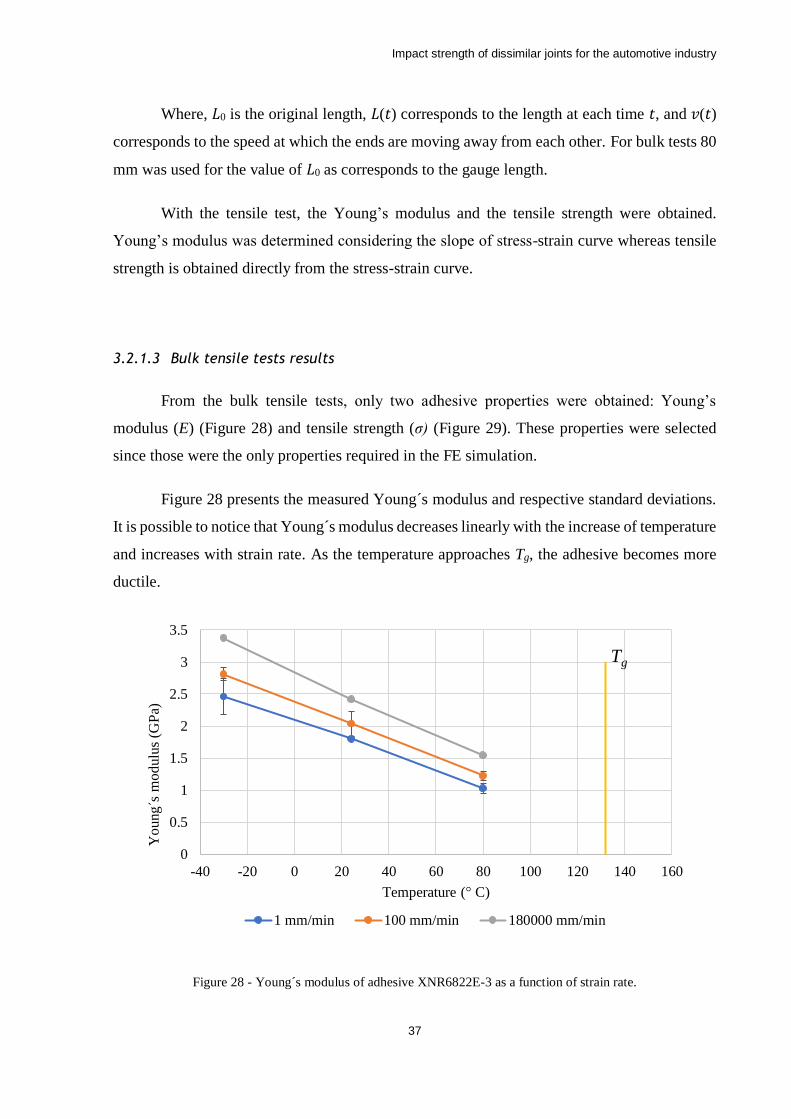
Impact strength of dissimilar joints for the automotive industry
37
Where, 𝐿0 is the original length, 𝐿(𝑡) corresponds to the length at each time 𝑡, and 𝑣(𝑡)
corresponds to the speed at which the ends are moving away from each other. For bulk tests 80
mm was used for the value of 𝐿0 as corresponds to the gauge length.
With the tensile test, the Young’s modulus and the tensile strength were obtained.
Young’s modulus was determined considering the slope of stress-strain curve whereas tensile
strength is obtained directly from the stress-strain curve.
3.2.1.3 Bulk tensile tests results
From the bulk tensile tests, only two adhesive properties were obtained: Young’s
modulus (E) (Figure 28) and tensile strength (σ) (Figure 29). These properties were selected
since those were the only properties required in the FE simulation.
Figure 28 presents the measured Young´s modulus and respective standard deviations.
It is possible to notice that Young´s modulus decreases linearly with the increase of temperature
and increases with strain rate. As the temperature approaches Tg, the adhesive becomes more
ductile.
Figure 28 - Young´s modulus of adhesive XNR6822E-3 as a function of strain rate.
0
0.5
1
1.5
2
2.5
3
3.5
-40 -20 0 20 40 60 80 100 120 140 160
Yo
ung´s
mo
dulu
s (G
Pa)
Temperature (° C)
1 mm/min 100 mm/min 180000 mm/min
Tg
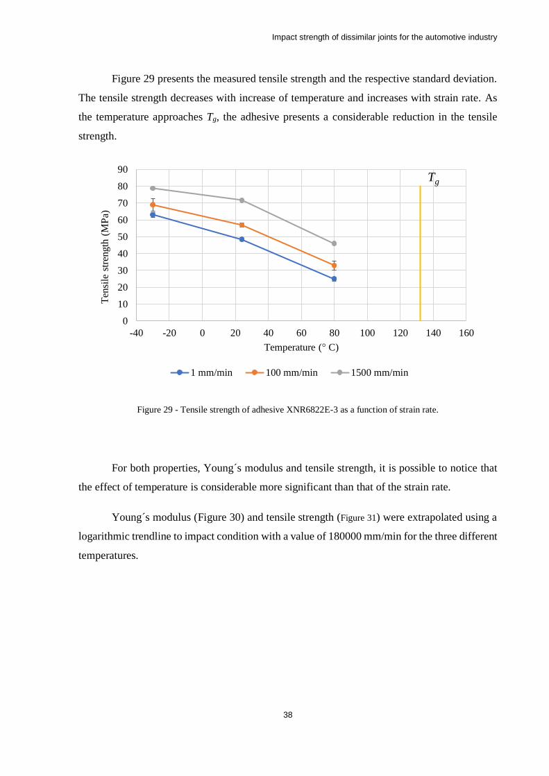
Impact strength of dissimilar joints for the automotive industry
38
Figure 29 presents the measured tensile strength and the respective standard deviation.
The tensile strength decreases with increase of temperature and increases with strain rate. As
the temperature approaches Tg, the adhesive presents a considerable reduction in the tensile
strength.
Figure 29 - Tensile strength of adhesive XNR6822E-3 as a function of strain rate.
For both properties, Young´s modulus and tensile strength, it is possible to notice that
the effect of temperature is considerable more significant than that of the strain rate.
Young´s modulus (Figure 30) and tensile strength (Figure 31) were extrapolated using a
logarithmic trendline to impact condition with a value of 180000 mm/min for the three different
temperatures.
0
10
20
30
40
50
60
70
80
90
-40 -20 0 20 40 60 80 100 120 140 160
Ten
sile
str
ength
(M
Pa)
Temperature (° C)
1 mm/min 100 mm/min 1500 mm/min
Tg
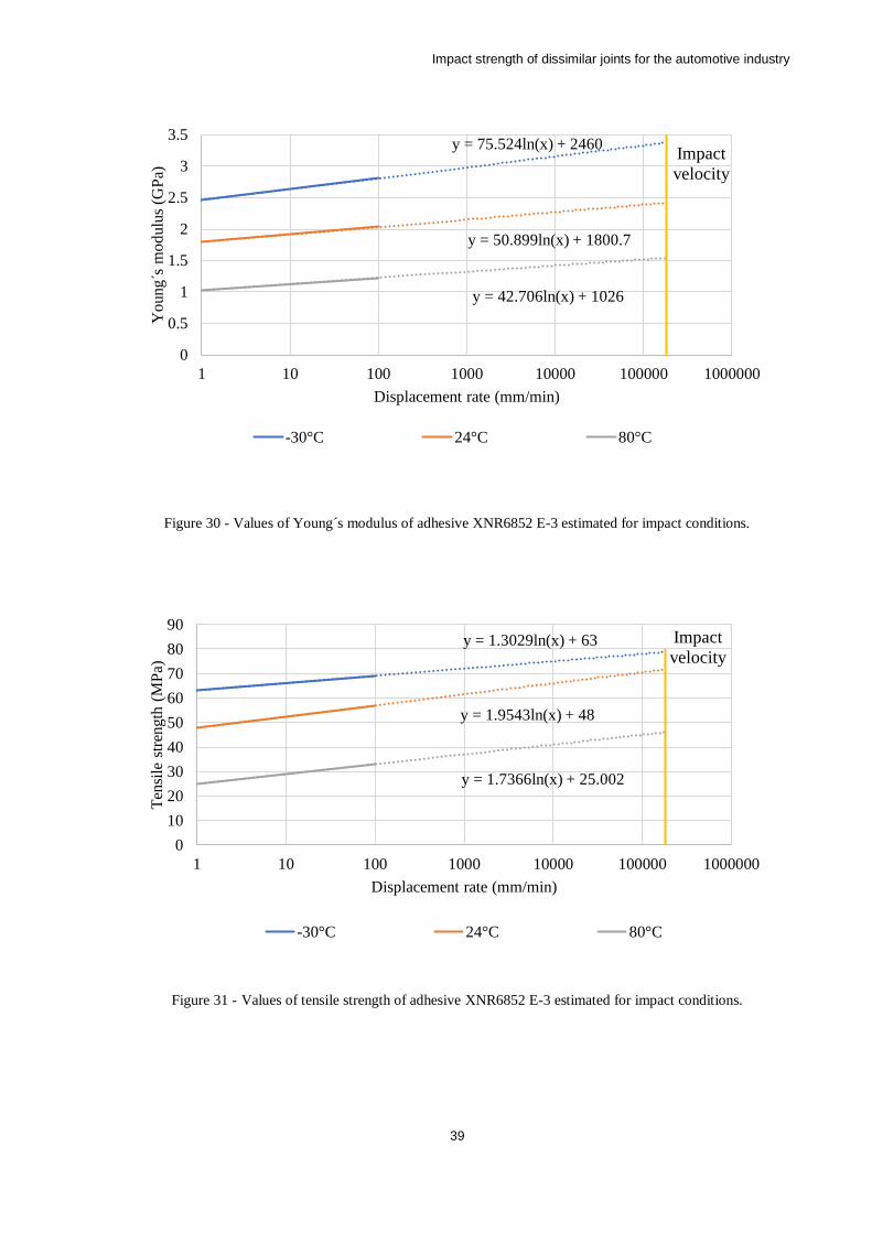
Impact strength of dissimilar joints for the automotive industry
39
Figure 30 - Values of Young´s modulus of adhesive XNR6852 E-3 estimated for impact conditions.
Figure 31 - Values of tensile strength of adhesive XNR6852 E-3 estimated for impact conditions.
y = 75.524ln(x) + 2460
y = 50.899ln(x) + 1800.7
y = 42.706ln(x) + 1026
0
0.5
1
1.5
2
2.5
3
3.5
1 10 100 1000 10000 100000 1000000
Yo
ung´s
mo
dulu
s (G
Pa)
Displacement rate (mm/min)
-30°C 24°C 80°C
Impact
velocity
y = 1.3029ln(x) + 63
y = 1.9543ln(x) + 48
y = 1.7366ln(x) + 25.002
0
10
20
30
40
50
60
70
80
90
1 10 100 1000 10000 100000 1000000
Ten
sile
str
ength
(M
Pa)
Displacement rate (mm/min)
-30°C 24°C 80°C
Impact
velocity

Impact strength of dissimilar joints for the automotive industry
40
3.2.2 Double cantilever beam
In this work DCB tests were selected to determine the fracture energy in mode I.
Because the need to determine the fracture energies at different temperatures, and the relatively
small size of the temperature chamber, an adaptation to the normalized specimens was made,
making then slightly shorter, changing the total length from 290 to 190 mm (Figure 32).
Figure 32 - DCB specimen geometry (dimensions in mm).
3.2.2.1 Manufacture
To obtain the fracture energies in mode I of the adhesive in study specimens were
produced according to the geometry represented in Figure 32. The substrates used were made
of steel (DIN 40 CrMnMo 8-6-4) to avoid plastic deformations (Figure 33).
Figure 33 - Adhesive applied in the open substrates.
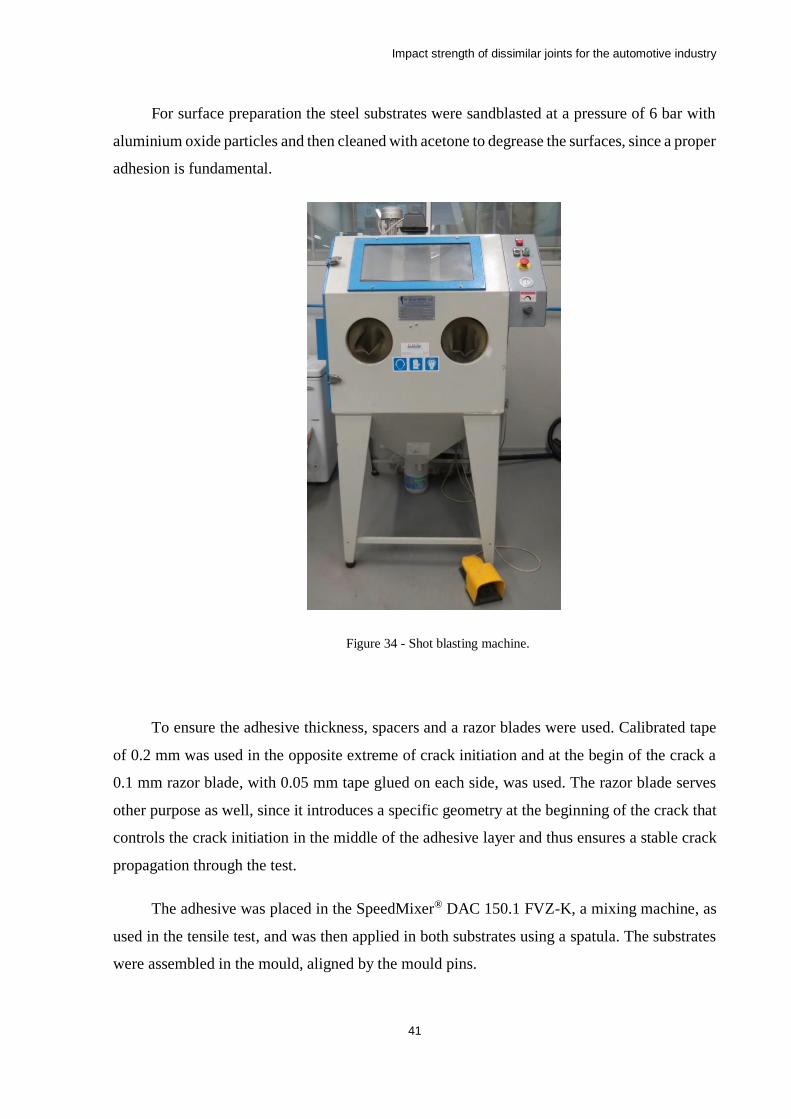
Impact strength of dissimilar joints for the automotive industry
41
For surface preparation the steel substrates were sandblasted at a pressure of 6 bar with
aluminium oxide particles and then cleaned with acetone to degrease the surfaces, since a proper
adhesion is fundamental.
Figure 34 - Shot blasting machine.
To ensure the adhesive thickness, spacers and a razor blades were used. Calibrated tape
of 0.2 mm was used in the opposite extreme of crack initiation and at the begin of the crack a
0.1 mm razor blade, with 0.05 mm tape glued on each side, was used. The razor blade serves
other purpose as well, since it introduces a specific geometry at the beginning of the crack that
controls the crack initiation in the middle of the adhesive layer and thus ensures a stable crack
propagation through the test.
The adhesive was placed in the SpeedMixer® DAC 150.1 FVZ-K, a mixing machine, as
used in the tensile test, and was then applied in both substrates using a spatula. The substrates
were assembled in the mould, aligned by the mould pins.
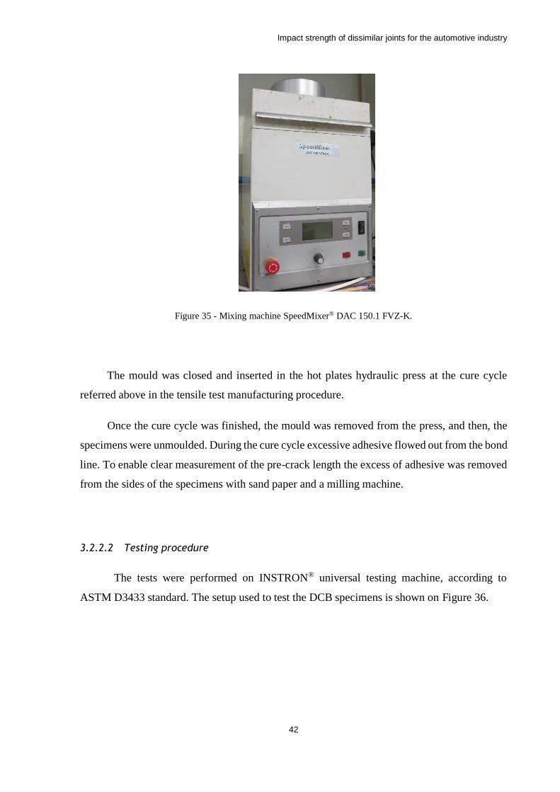
Impact strength of dissimilar joints for the automotive industry
42
Figure 35 - Mixing machine SpeedMixer® DAC 150.1 FVZ-K.
The mould was closed and inserted in the hot plates hydraulic press at the cure cycle
referred above in the tensile test manufacturing procedure.
Once the cure cycle was finished, the mould was removed from the press, and then, the
specimens were unmoulded. During the cure cycle excessive adhesive flowed out from the bond
line. To enable clear measurement of the pre-crack length the excess of adhesive was removed
from the sides of the specimens with sand paper and a milling machine.
3.2.2.2 Testing procedure
The tests were performed on INSTRON® universal testing machine, according to
ASTM D3433 standard. The setup used to test the DCB specimens is shown on Figure 36.
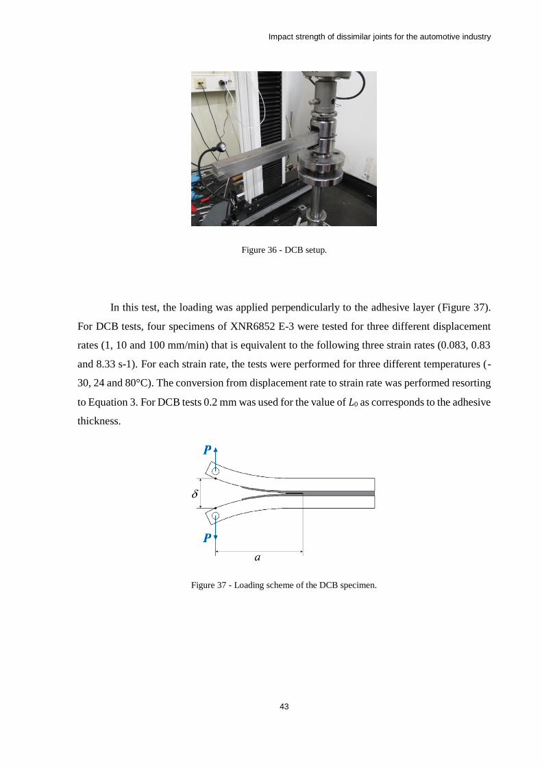
Impact strength of dissimilar joints for the automotive industry
43
Figure 36 - DCB setup.
In this test, the loading was applied perpendicularly to the adhesive layer (Figure 37).
For DCB tests, four specimens of XNR6852 E-3 were tested for three different displacement
rates (1, 10 and 100 mm/min) that is equivalent to the following three strain rates (0.083, 0.83
and 8.33 s-1). For each strain rate, the tests were performed for three different temperatures (-
30, 24 and 80°C). The conversion from displacement rate to strain rate was performed resorting
to Equation 3. For DCB tests 0.2 mm was used for the value of 𝐿0 as corresponds to the adhesive
thickness.
Figure 37 - Loading scheme of the DCB specimen.
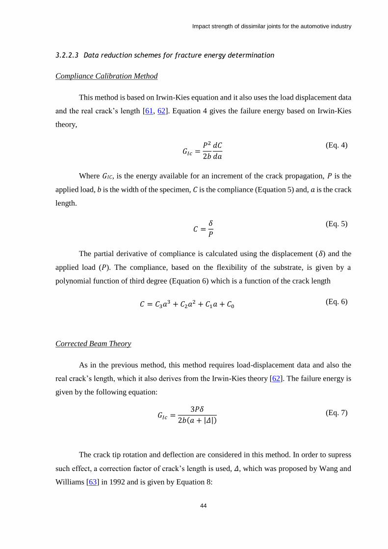
Impact strength of dissimilar joints for the automotive industry
44
3.2.2.3 Data reduction schemes for fracture energy determination
Compliance Calibration Method
This method is based on Irwin-Kies equation and it also uses the load displacement data
and the real crack’s length [61, 62]. Equation 4 gives the failure energy based on Irwin-Kies
theory,
𝐺𝐼𝑐 =
𝑃2
2𝑏
𝑑𝐶
𝑑𝑎
(Eq. 4)
Where 𝐺𝐼𝐶, is the energy available for an increment of the crack propagation, 𝑃 is the
applied load, b is the width of the specimen, 𝐶 is the compliance (Equation 5) and, 𝑎 is the crack
length.
𝐶 =
𝛿
𝑃
(Eq. 5)
The partial derivative of compliance is calculated using the displacement (𝛿) and the
applied load (𝑃). The compliance, based on the flexibility of the substrate, is given by a
polynomial function of third degree (Equation 6) which is a function of the crack length
𝐶 = 𝐶3𝑎3 + 𝐶2𝑎2 + 𝐶1𝑎 + 𝐶0 (Eq. 6)
Corrected Beam Theory
As in the previous method, this method requires load-displacement data and also the
real crack’s length, which it also derives from the Irwin-Kies theory [62]. The failure energy is
given by the following equation:
𝐺𝐼𝑐 =3𝑃𝛿
2𝑏(𝑎 + |𝛥|) (Eq. 7)
The crack tip rotation and deflection are considered in this method. In order to supress
such effect, a correction factor of crack’s length is used, 𝛥, which was proposed by Wang and
Williams [63] in 1992 and is given by Equation 8:
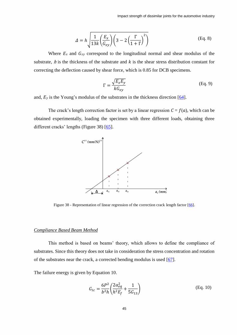
Impact strength of dissimilar joints for the automotive industry
45
𝛥 = ℎ√1
13𝑘(
𝐸𝑥
𝐺𝑥𝑦) (3 − 2 (
Γ
1 + Γ)
2
) (Eq. 8)
Where 𝐸𝑥 and 𝐺𝑥𝑦 correspond to the longitudinal normal and shear modulus of the
substrate, h is the thickness of the substrate and 𝑘 is the shear stress distribution constant for
correcting the deflection caused by shear force, which is 0.85 for DCB specimens.
Γ =√𝐸𝑥𝐸𝑦
𝑘𝐺𝑥𝑦 (Eq. 9)
and, 𝐸𝑦 is the Young’s modulus of the substrates in the thickness direction [64].
The crack’s length correction factor is set by a linear regression 𝐶 = 𝑓(𝑎), which can be
obtained experimentally, loading the specimen with three different loads, obtaining three
different cracks’ lengths (Figure 38) [65].
Figure 38 - Representation of linear regression of the correction crack length factor [66].
Compliance Based Beam Method
This method is based on beams’ theory, which allows to define the compliance of
substrates. Since this theory does not take in consideration the stress concentration and rotation
of the substrates near the crack, a corrected bending modulus is used [67].
The failure energy is given by Equation 10.
𝐺𝐼𝑐 =6𝑃2
𝑏2ℎ(
2𝑎𝑒𝑞2
ℎ2𝐸𝑓+
1
5𝐺13) (Eq. 10)
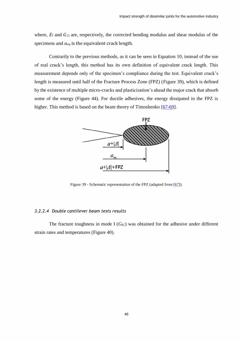
Impact strength of dissimilar joints for the automotive industry
46
where, 𝐸f and 𝐺13 are, respectively, the corrected bending modulus and shear modulus of the
specimens and 𝑎𝑒q is the equivalent crack length.
Contrarily to the previous methods, as it can be seen in Equation 10, instead of the use
of real crack’s length, this method has its own definition of equivalent crack length. This
measurement depends only of the specimen’s compliance during the test. Equivalent crack’s
length is measured until half of the Fracture Process Zone (FPZ) (Figure 39), which is defined
by the existence of multiple micro-cracks and plasticization’s ahead the major crack that absorb
some of the energy (Figure 44). For ductile adhesives, the energy dissipated in the FPZ is
higher. This method is based on the beam theory of Timoshenko [67-69].
Figure 39 - Schematic representation of the FPZ (adapted from [67]).
3.2.2.4 Double cantilever beam tests results
The fracture toughness in mode I (GIC) was obtained for the adhesive under different
strain rates and temperatures (Figure 40).
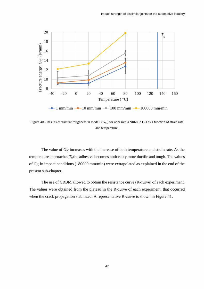
Impact strength of dissimilar joints for the automotive industry
47
Figure 40 - Results of fracture toughness in mode I (GIC) for adhesive XNR6852 E-3 as a function of strain rate
and temperature.
The value of GIC increases with the increase of both temperature and strain rate. As the
temperature approaches Tg the adhesive becomes noticeably more ductile and tough. The values
of GIC in impact conditions (180000 mm/min) were extrapolated as explained in the end of the
present sub-chapter.
The use of CBBM allowed to obtain the resistance curve (R-curve) of each experiment.
The values were obtained from the plateau in the R-curve of each experiment, that occurred
when the crack propagation stabilized. A representative R-curve is shown in Figure 41.
8
10
12
14
16
18
20
-40 -20 0 20 40 60 80 100 120 140 160
Fra
cture
ener
gy,
GIC
(N/m
m)
Temperature ( °C)
1 mm/min 10 mm/min 100 mm/min 180000 mm/min
Tg
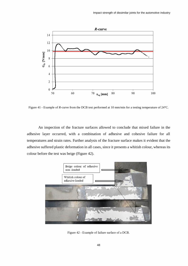
Impact strength of dissimilar joints for the automotive industry
48
Figure 41 - Example of R-curve from the DCB test performed at 10 mm/min for a testing temperature of 24°C.
An inspection of the fracture surfaces allowed to conclude that mixed failure in the
adhesive layer occurred, with a combination of adhesive and cohesive failure for all
temperatures and strain rates. Further analysis of the fracture surface makes it evident that the
adhesive suffered plastic deformation in all cases, since it presents a whitish colour, whereas its
colour before the test was beige (Figure 42).
Figure 42 - Example of failure surface of a DCB.
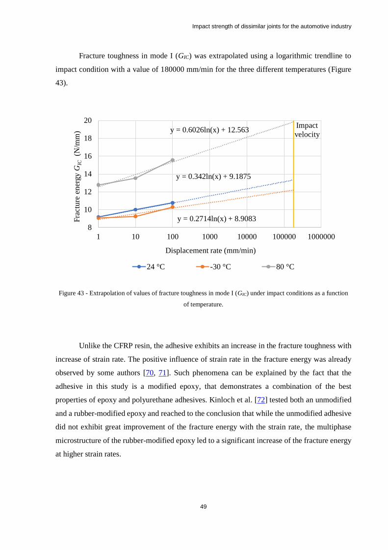
Impact strength of dissimilar joints for the automotive industry
49
Fracture toughness in mode I (GIC) was extrapolated using a logarithmic trendline to
impact condition with a value of 180000 mm/min for the three different temperatures (Figure
43).
Figure 43 - Extrapolation of values of fracture toughness in mode I (GIC) under impact conditions as a function
of temperature.
Unlike the CFRP resin, the adhesive exhibits an increase in the fracture toughness with
increase of strain rate. The positive influence of strain rate in the fracture energy was already
observed by some authors [70, 71]. Such phenomena can be explained by the fact that the
adhesive in this study is a modified epoxy, that demonstrates a combination of the best
properties of epoxy and polyurethane adhesives. Kinloch et al. [72] tested both an unmodified
and a rubber-modified epoxy and reached to the conclusion that while the unmodified adhesive
did not exhibit great improvement of the fracture energy with the strain rate, the multiphase
microstructure of the rubber-modified epoxy led to a significant increase of the fracture energy
at higher strain rates.
y = 0.342ln(x) + 9.1875
y = 0.2714ln(x) + 8.9083
y = 0.6026ln(x) + 12.563
8
10
12
14
16
18
20
1 10 100 1000 10000 100000 1000000
Fra
cture
ener
gy G
IC(N
/mm
)
Displacement rate (mm/min)
24 °C -30 °C 80 °C
Impact
velocity
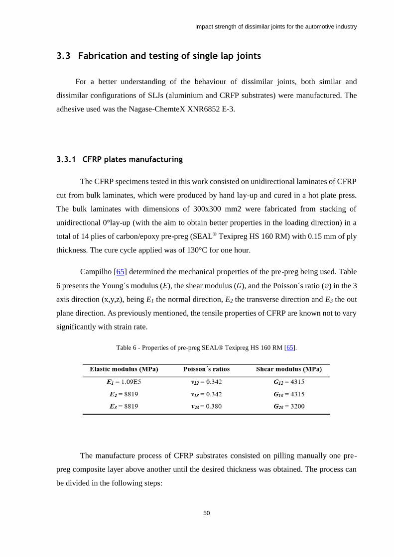
Impact strength of dissimilar joints for the automotive industry
50
3.3 Fabrication and testing of single lap joints
For a better understanding of the behaviour of dissimilar joints, both similar and
dissimilar configurations of SLJs (aluminium and CRFP substrates) were manufactured. The
adhesive used was the Nagase-ChemteX XNR6852 E-3.
3.3.1 CFRP plates manufacturing
The CFRP specimens tested in this work consisted on unidirectional laminates of CFRP
cut from bulk laminates, which were produced by hand lay-up and cured in a hot plate press.
The bulk laminates with dimensions of 300x300 mm2 were fabricated from stacking of
unidirectional 0°lay-up (with the aim to obtain better properties in the loading direction) in a
total of 14 plies of carbon/epoxy pre-preg (SEAL® Texipreg HS 160 RM) with 0.15 mm of ply
thickness. The cure cycle applied was of 130°C for one hour.
Campilho [65] determined the mechanical properties of the pre-preg being used. Table
6 presents the Young´s modulus (𝐸), the shear modulus (𝐺), and the Poisson´s ratio (𝑣) in the 3
axis direction (x,y,z), being E1 the normal direction, E2 the transverse direction and E3 the out
plane direction. As previously mentioned, the tensile properties of CFRP are known not to vary
significantly with strain rate.
Table 6 - Properties of pre-preg SEAL® Texipreg HS 160 RM [65].
The manufacture process of CFRP substrates consisted on pilling manually one pre-
preg composite layer above another until the desired thickness was obtained. The process can
be divided in the following steps:
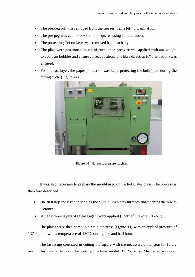
Impact strength of dissimilar joints for the automotive industry
51
• The prepreg roll was removed from the freezer, being left to warm at RT;
• The pre-peg was cut in 300x300 mm squares using a metal cutter;
• The protecting Teflon layer was removed from each ply;
• The plies were positioned on top of each other, pressure was applied with one weight
to avoid air bubbles and ensure correct position. The fibre direction (0º orientation) was
ensured;
• For the last layer, the paper protection was kept, protecting the bulk plate during the
curing cycle (Figure 44).
Figure 44 - Hot press pressure machine.
It was also necessary to prepare the mould used on the hot plates press. The process is
therefore described.
• The first step consisted in sanding the aluminium plates surfaces and cleaning them with
acetone;
• At least three layers of release agent were applied (Loctite® Frekote 770-NC).
The plates were then cured in a hot plate press (Figure 44) with an applied pressure of
137 bar and with a temperature of 150°C during one and half hour.
The last stage consisted in cutting the square with the necessary dimension for future
use. In this case, a diamond disc cutting machine, model DV 25 Batisti Meccanica was used
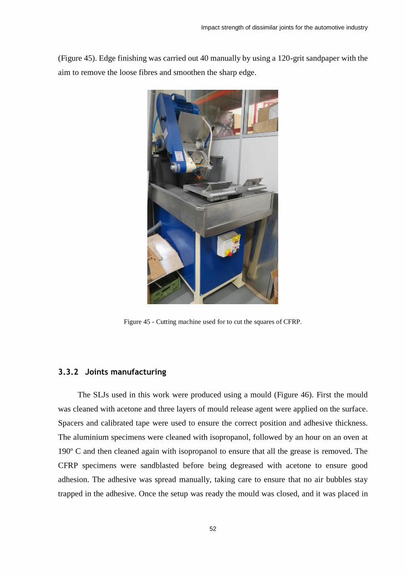
Impact strength of dissimilar joints for the automotive industry
52
(Figure 45). Edge finishing was carried out 40 manually by using a 120-grit sandpaper with the
aim to remove the loose fibres and smoothen the sharp edge.
Figure 45 - Cutting machine used for to cut the squares of CFRP.
3.3.2 Joints manufacturing
The SLJs used in this work were produced using a mould (Figure 46). First the mould
was cleaned with acetone and three layers of mould release agent were applied on the surface.
Spacers and calibrated tape were used to ensure the correct position and adhesive thickness.
The aluminium specimens were cleaned with isopropanol, followed by an hour on an oven at
190º C and then cleaned again with isopropanol to ensure that all the grease is removed. The
CFRP specimens were sandblasted before being degreased with acetone to ensure good
adhesion. The adhesive was spread manually, taking care to ensure that no air bubbles stay
trapped in the adhesive. Once the setup was ready the mould was closed, and it was placed in
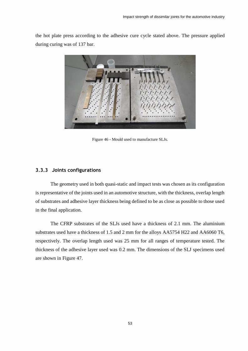
Impact strength of dissimilar joints for the automotive industry
53
the hot plate press according to the adhesive cure cycle stated above. The pressure applied
during curing was of 137 bar.
Figure 46 - Mould used to manufacture SLJs.
3.3.3 Joints configurations
The geometry used in both quasi-static and impact tests was chosen as its configuration
is representative of the joints used in an automotive structure, with the thickness, overlap length
of substrates and adhesive layer thickness being defined to be as close as possible to those used
in the final application.
The CFRP substrates of the SLJs used have a thickness of 2.1 mm. The aluminium
substrates used have a thickness of 1.5 and 2 mm for the alloys AA5754 H22 and AA6060 T6,
respectively. The overlap length used was 25 mm for all ranges of temperature tested. The
thickness of the adhesive layer used was 0.2 mm. The dimensions of the SLJ specimens used
are shown in Figure 47.
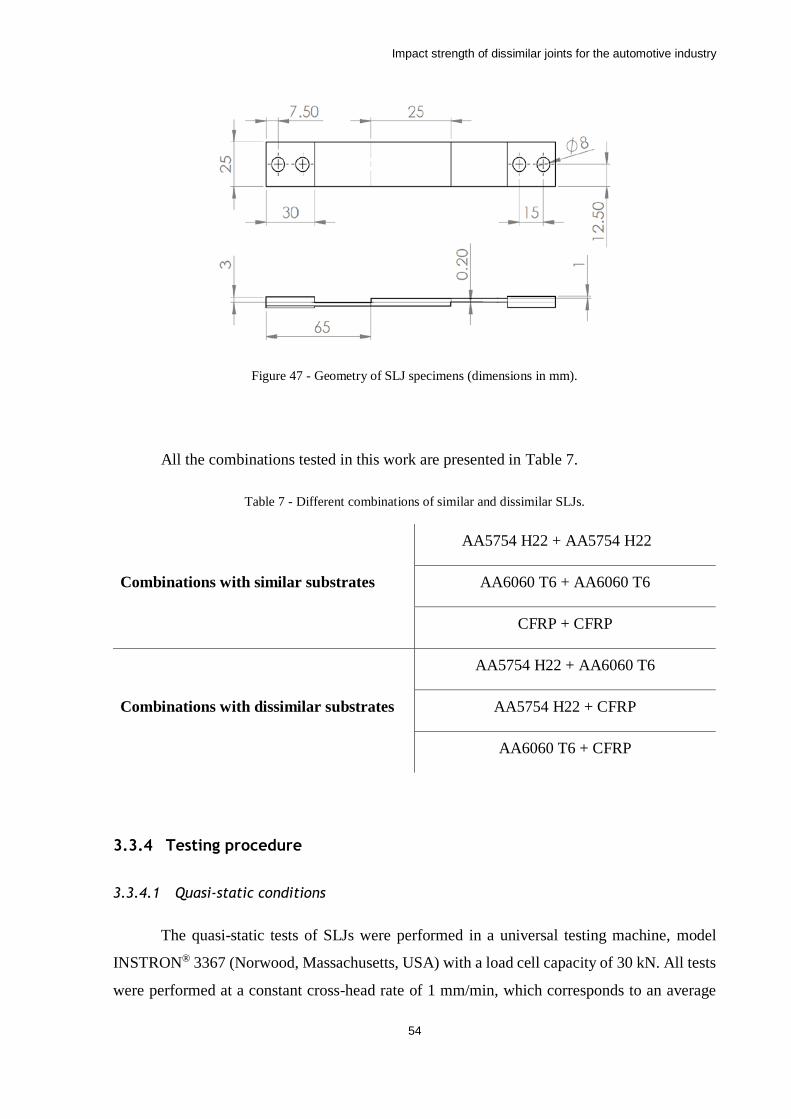
Impact strength of dissimilar joints for the automotive industry
54
Figure 47 - Geometry of SLJ specimens (dimensions in mm).
All the combinations tested in this work are presented in Table 7.
Table 7 - Different combinations of similar and dissimilar SLJs.
Combinations with similar substrates
AA5754 H22 + AA5754 H22
AA6060 T6 + AA6060 T6
CFRP + CFRP
Combinations with dissimilar substrates
AA5754 H22 + AA6060 T6
AA5754 H22 + CFRP
AA6060 T6 + CFRP
3.3.4 Testing procedure
3.3.4.1 Quasi-static conditions
The quasi-static tests of SLJs were performed in a universal testing machine, model
INSTRON® 3367 (Norwood, Massachusetts, USA) with a load cell capacity of 30 kN. All tests
were performed at a constant cross-head rate of 1 mm/min, which corresponds to an average
Impact strength of dissimilar joints for the automotive industry
55
strain rate of 0.08 s-1 in the adhesive layer. The conversion from displacement rate to strain rate
was performed resorting to Equation 3. For SLJs tests 0.2 mm was used for the value of 𝐿0 as
corresponds to the adhesive thickness.
In tests performed under LT (low temperature) and HT (high temperature), a heated
climatic chamber was integrated in the testing machine. In the case of LT, the same chamber
was used, with nitrogen being injected in a controlled manner to achieve the lower temperature.
With the use of a thermocouple positioned in contact with each SLJ the temperature was
measured, ensuring a homogeneous temperature distribution. Each test was only performed
after a period of 10 minutes at the intended temperature. While the tests were being performed
the SLJs remained enclosed in the chamber under a constant temperature.
A total of four specimens were tested for each overlap and temperature condition, and
force-displacement (P-δ) curves were obtained for all SLJs tested.
3.3.4.2 Impact conditions
The impact tests were performed in a Rosand® Instrumented Falling weight impact
tester, type 5 H.V. (Stourbridge, West Midlands, U.K.) coupled with a load cell of 60 kN. This
equipment consists of a mass being dropped from a certain height, until it impacts the specimen.
The specimen is mounted and kept vertically with the use of a specially designed grip. The
impactor strikes the lower section of the grip, accelerating the test assembly so that the specimen
is loaded in tension-shear. A total impactor weight of 26 kg was used in the setup of the testing
machine. An impact speed of 3 m/s was used, corresponding to an available impact energy of
117 J.
For tests performed at LT, gaseous nitrogen was applied directly in every SLJ. In the
case of HT, a heat gun to heat-up the SLJs was used. In both stages of temperature, a
thermocouple was attached in the beginning of the area of overlap length to measure and control
the temperature of the specimen. Each test occurred when the adhesive layer temperature was
found to be stabilized at the desired value.
A total of four specimens were tested for each overlap and temperature condition, and
a P-δ curve was obtained for each SLJ tested.
Impact strength of dissimilar joints for the automotive industry
56
4 Numerical simulation details
A numerical analysis was performed to predict the SLJ strength under quasi-static and
impact conditions. For this purpose, Abaqus® (Dassault Systèmes, Suresnes, France) was FEA
software used. Quasi-static and dynamical simulations were only developed for RT because
there was no information available regarding cohesive properties for the adhesive and the
substrates at low and high temperature.
P-δ curves were determined and the prediction of the failure load was recorded. The
software also allows to extracted information regarding crack initiation and propagation and
state of plasticity from cohesive elements.
4.1 Cohesive zone modelling
The triangular CZM was used due to its simplicity and common use in previous studies.
This model is available in the Abaqus® and enables the use of mixed mode loading (Figure 22).
The adhesive layer was modelled with 0.2 mm thick cohesive elements, the same thickness of
the adhesive layer to control the zone of crack initiation.
4.2 Quasi-static model
For the numerical simulation, a few conditions were considered with the objective of
making the models as reliable as possible. Since three distinct types of materials were used
during this work, the elements used to simulate them need to be chosen according to their
physical behaviour. Figure 48 shows the model of a dissimilar joint with aluminium and CFRP
substrates, where all the different types of elements used in all the possible configurations are
presented. As mentioned before, for the adhesive a 0.2 mm layer was modelled with cohesive
elements. For CFRP substrates elastic orthotropic properties (engineering constants) were used
but it was also necessary to resort to cohesive elements to predict a possible failure by
delamination. To simulate this type of failure, a 0.15 mm layer was added at 0.15 mm from the
interface between adhesive and CFRP. The thickness of 0.15 mm corresponds to one ply of the
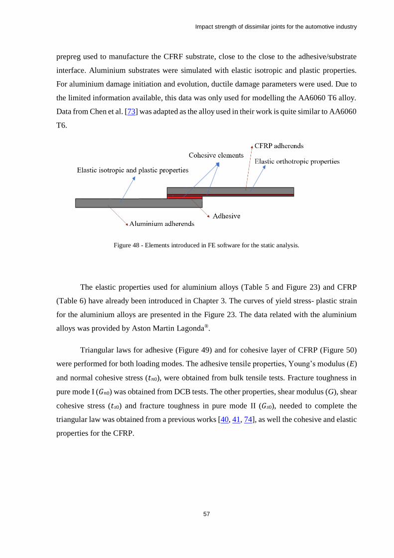
Impact strength of dissimilar joints for the automotive industry
57
prepreg used to manufacture the CFRF substrate, close to the close to the adhesive/substrate
interface. Aluminium substrates were simulated with elastic isotropic and plastic properties.
For aluminium damage initiation and evolution, ductile damage parameters were used. Due to
the limited information available, this data was only used for modelling the AA6060 T6 alloy.
Data from Chen et al. [73] was adapted as the alloy used in their work is quite similar to AA6060
T6.
Figure 48 - Elements introduced in FE software for the static analysis.
The elastic properties used for aluminium alloys (Table 5 and Figure 23) and CFRP
(Table 6) have already been introduced in Chapter 3. The curves of yield stress- plastic strain
for the aluminium alloys are presented in the Figure 23. The data related with the aluminium
alloys was provided by Aston Martin Lagonda®.
Triangular laws for adhesive (Figure 49) and for cohesive layer of CFRP (Figure 50)
were performed for both loading modes. The adhesive tensile properties, Young’s modulus (E)
and normal cohesive stress (𝑡𝑛0), were obtained from bulk tensile tests. Fracture toughness in
pure mode I (𝐺𝑛0) was obtained from DCB tests. The other properties, shear modulus (G), shear
cohesive stress (𝑡𝑠0) and fracture toughness in pure mode II (𝐺𝑠0), needed to complete the
triangular law was obtained from a previous works [40, 41, 74], as well the cohesive and elastic
properties for the CFRP.
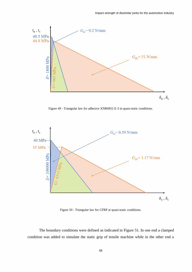
Impact strength of dissimilar joints for the automotive industry
58
Figure 49 - Triangular law for adhesive XNR6852 E-3 in quasi-static conditions.
Figure 50 - Triangular law for CFRP at quasi-static conditions.
The boundary conditions were defined as indicated in Figure 51. In one end a clamped
condition was added to simulate the static grip of tensile machine while in the other end a
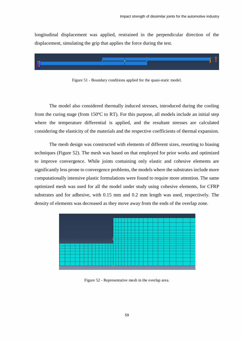
Impact strength of dissimilar joints for the automotive industry
59
longitudinal displacement was applied, restrained in the perpendicular direction of the
displacement, simulating the grip that applies the force during the test.
Figure 51 - Boundary conditions applied for the quasi-static model.
The model also considered thermally induced stresses, introduced during the cooling
from the curing stage (from 150ºC to RT). For this purpose, all models include an initial step
where the temperature differential is applied, and the resultant stresses are calculated
considering the elasticity of the materials and the respective coefficients of thermal expansion.
The mesh design was constructed with elements of different sizes, resorting to biasing
techniques (Figure 52). The mesh was based on that employed for prior works and optimized
to improve convergence. While joints containing only elastic and cohesive elements are
significantly less prone to convergence problems, the models where the substrates include more
computationally intensive plastic formulations were found to require more attention. The same
optimized mesh was used for all the model under study using cohesive elements, for CFRP
substrates and for adhesive, with 0.15 mm and 0.2 mm length was used, respectively. The
density of elements was decreased as they move away from the ends of the overlap zone.
Figure 52 - Representative mesh in the overlap area.

Impact strength of dissimilar joints for the automotive industry
60
For the visualization of the level of CZM degradation, scalar stiffness degradation
(SDEG) was requested in the field outputs. This also enables the monitoring of the crack
propagation.
Regarding to the element types, the bondline area was defined as a 4-node-two-
dimensional cohesive element (COH2D4) and substrates were defined as a 4-node bilinear
plane stress quadrilateral, reduced integration, hourglass control (CPS4R).
4.3 Dynamical model
To recreate the impact conditions of the drop weight test, a two-dimensional model was
created resorting to Abaqus/Explicit. Most crash simulations are based on explicit FE-codes
since these can simulate fast events within a reasonable execution time. Geometrically wise,
the model was similar to the one used for quasi-static simulations with one modification, the
addition of a mass to the non-clamped edge that represents the impact block in the experimental
tests.
The boundary conditions were like those used in the static model with the difference
being instead of a longitudinal displacement in the non-clamped end of the joint, a velocity field
of 3000 mm/s was applied to mass that was added to the model (Figure 53). To simulate the
117 Joules of impact energy with a 3m/s velocity of the mass, the density was defined to
guarantee that the mass was 26 kg. The mesh geometry used was the same as the static model
and SDEG field output was also requested.
Figure 53 - Boundary conditions applied for the impact model.
Following the same procedure described for the quasi-static model, the dynamical
model also included thermally induced stresses during cooling.
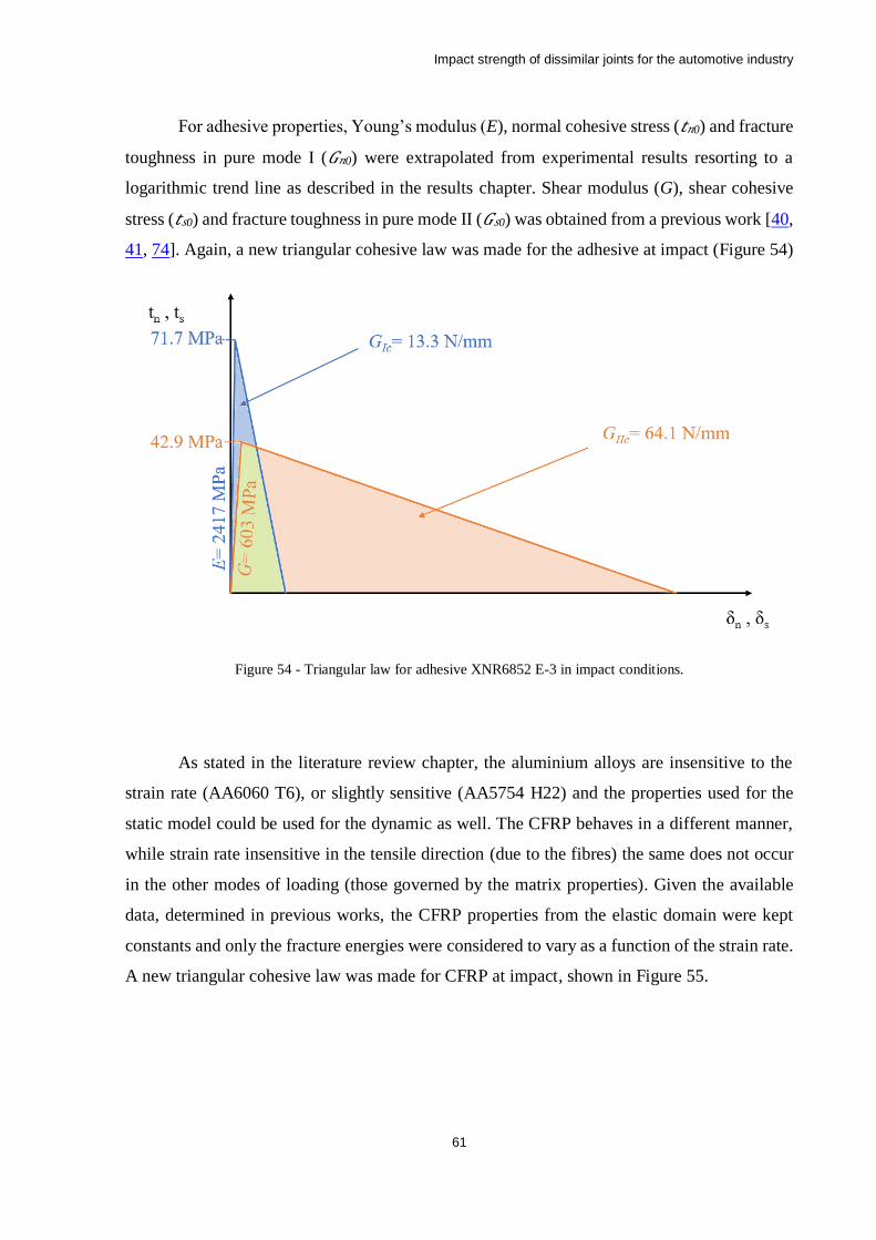
Impact strength of dissimilar joints for the automotive industry
61
For adhesive properties, Young’s modulus (E), normal cohesive stress (𝑡𝑛0) and fracture
toughness in pure mode I (𝐺𝑛0) were extrapolated from experimental results resorting to a
logarithmic trend line as described in the results chapter. Shear modulus (G), shear cohesive
stress (𝑡𝑠0) and fracture toughness in pure mode II (𝐺𝑠0) was obtained from a previous work [40,
41, 74]. Again, a new triangular cohesive law was made for the adhesive at impact (Figure 54)
Figure 54 - Triangular law for adhesive XNR6852 E-3 in impact conditions.
As stated in the literature review chapter, the aluminium alloys are insensitive to the
strain rate (AA6060 T6), or slightly sensitive (AA5754 H22) and the properties used for the
static model could be used for the dynamic as well. The CFRP behaves in a different manner,
while strain rate insensitive in the tensile direction (due to the fibres) the same does not occur
in the other modes of loading (those governed by the matrix properties). Given the available
data, determined in previous works, the CFRP properties from the elastic domain were kept
constants and only the fracture energies were considered to vary as a function of the strain rate.
A new triangular cohesive law was made for CFRP at impact, shown in Figure 55.
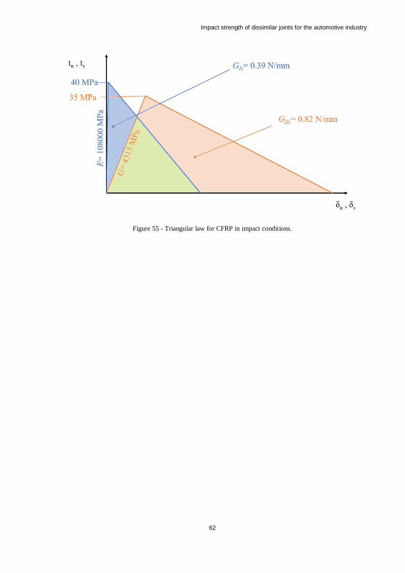
Impact strength of dissimilar joints for the automotive industry
62
Figure 55 - Triangular law for CFRP in impact conditions.

Impact strength of dissimilar joints for the automotive industry
63
5 Results and discussion
5.1 Experimental results
5.1.1 Quasi-static tests
For quasi-static tests of SLJs, although four specimens were tested for each combination
of substrates and for three different temperatures, only three tests were considered as valid
results for most configurations. This was due to surface contamination of some specimens,
which failed with almost negligible load even after careful degreasing. The tests were
performed with a displacement rate of 1 mm/min. The load, displacement and energy were
recorded by the universal testing machine.
5.1.1.1 Joints with similar substrates
Figure 56 shows the representative P-δ curves for SLJs with similar substrates at RT for
quasi-static conditions. SLJs with aluminium substrates exhibits a significantly large
deformation in the plastic domain while SLJs with CFRP substrates, despite the larger failure
load, presents a brittle behaviour.
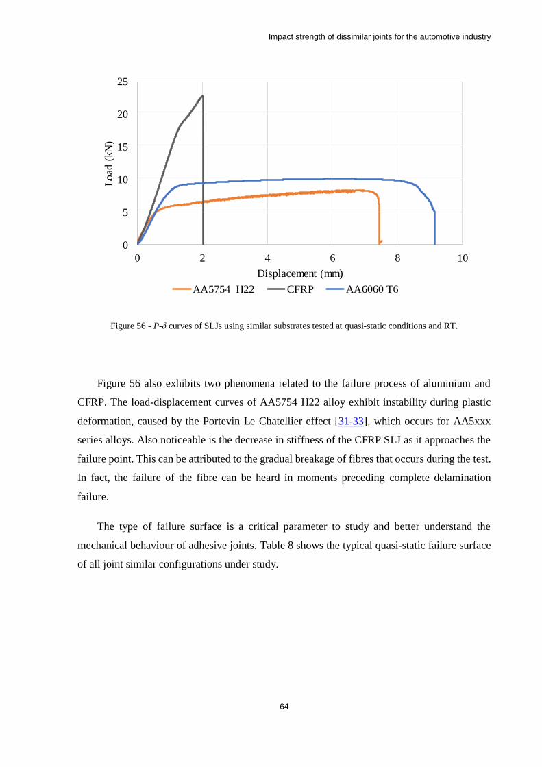
Impact strength of dissimilar joints for the automotive industry
64
Figure 56 - P-δ curves of SLJs using similar substrates tested at quasi-static conditions and RT.
Figure 56 also exhibits two phenomena related to the failure process of aluminium and
CFRP. The load-displacement curves of AA5754 H22 alloy exhibit instability during plastic
deformation, caused by the Portevin Le Chatellier effect [31-33], which occurs for AA5xxx
series alloys. Also noticeable is the decrease in stiffness of the CFRP SLJ as it approaches the
failure point. This can be attributed to the gradual breakage of fibres that occurs during the test.
In fact, the failure of the fibre can be heard in moments preceding complete delamination
failure.
The type of failure surface is a critical parameter to study and better understand the
mechanical behaviour of adhesive joints. Table 8 shows the typical quasi-static failure surface
of all joint similar configurations under study.
0
5
10
15
20
25
0 2 4 6 8 10
Load
(kN
)
Displacement (mm)
AA5754 H22 CFRP AA6060 T6
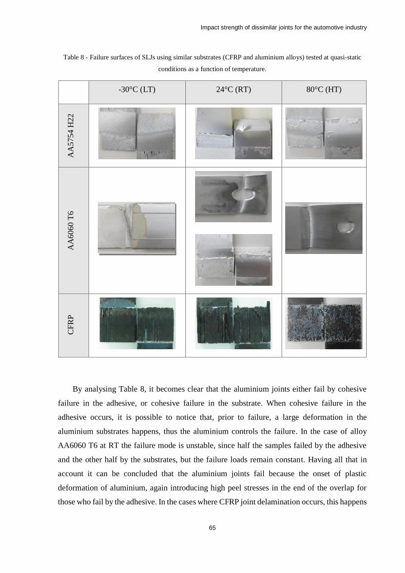
Impact strength of dissimilar joints for the automotive industry
65
Table 8 - Failure surfaces of SLJs using similar substrates (CFRP and aluminium alloys) tested at quasi-static
conditions as a function of temperature.
-30°C (LT) 24°C (RT) 80°C (HT)
AA
5754 H
22
AA
6060
T6
CF
RP
By analysing Table 8, it becomes clear that the aluminium joints either fail by cohesive
failure in the adhesive, or cohesive failure in the substrate. When cohesive failure in the
adhesive occurs, it is possible to notice that, prior to failure, a large deformation in the
aluminium substrates happens, thus the aluminium controls the failure. In the case of alloy
AA6060 T6 at RT the failure mode is unstable, since half the samples failed by the adhesive
and the other half by the substrates, but the failure loads remain constant. Having all that in
account it can be concluded that the aluminium joints fail because the onset of plastic
deformation of aluminium, again introducing high peel stresses in the end of the overlap for
those who fail by the adhesive. In the cases where CFRP joint delamination occurs, this happens
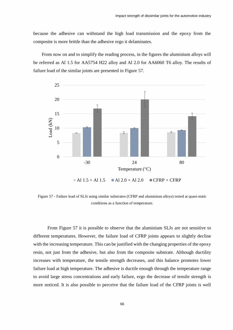
Impact strength of dissimilar joints for the automotive industry
66
because the adhesive can withstand the high load transmission and the epoxy from the
composite is more brittle than the adhesive ergo it delaminates.
From now on and to simplify the reading process, in the figures the aluminium alloys will
be referred as Al 1.5 for AA5754 H22 alloy and Al 2.0 for AA6060 T6 alloy. The results of
failure load of the similar joints are presented in Figure 57.
Figure 57 - Failure load of SLJs using similar substrates (CFRP and aluminium alloys) tested at quasi-static
conditions as a function of temperature.
From Figure 57 it is possible to observe that the aluminium SLJs are not sensitive to
different temperatures. However, the failure load of CFRP joints appears to slightly decline
with the increasing temperature. This can be justified with the changing properties of the epoxy
resin, not just from the adhesive, but also from the composite substrate. Although ductility
increases with temperature, the tensile strength decreases, and this balance promotes lower
failure load at high temperature. The adhesive is ductile enough through the temperature range
to avoid large stress concentrations and early failure, ergo the decrease of tensile strength is
more noticed. It is also possible to perceive that the failure load of the CFRP joints is well
0
5
10
15
20
25
30 24 80
Load
(kN
)
Temperature (°C)
Al 1.5 + Al 1.5 Al 2.0 + Al 2.0 CFRP + CFRP
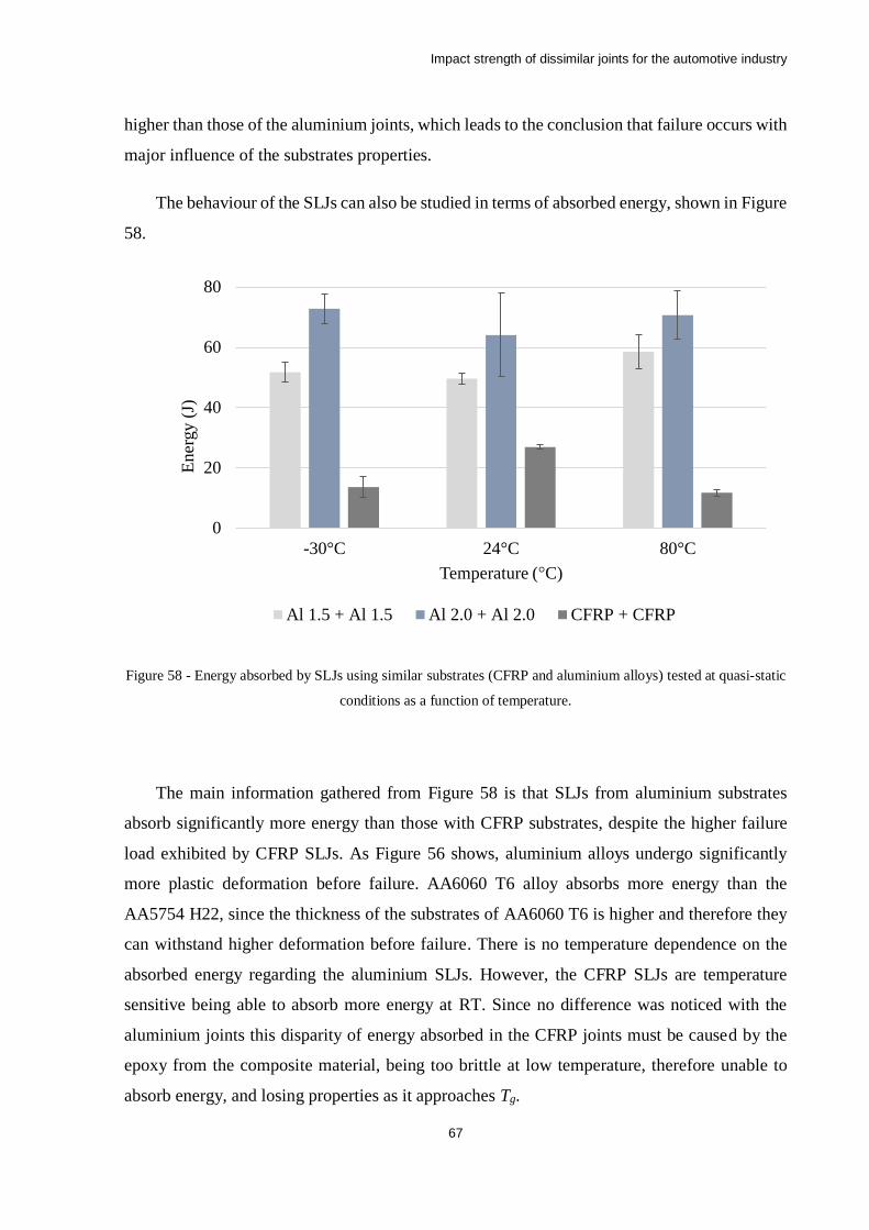
Impact strength of dissimilar joints for the automotive industry
67
higher than those of the aluminium joints, which leads to the conclusion that failure occurs with
major influence of the substrates properties.
The behaviour of the SLJs can also be studied in terms of absorbed energy, shown in Figure
58.
Figure 58 - Energy absorbed by SLJs using similar substrates (CFRP and aluminium alloys) tested at quasi-static
conditions as a function of temperature.
The main information gathered from Figure 58 is that SLJs from aluminium substrates
absorb significantly more energy than those with CFRP substrates, despite the higher failure
load exhibited by CFRP SLJs. As Figure 56 shows, aluminium alloys undergo significantly
more plastic deformation before failure. AA6060 T6 alloy absorbs more energy than the
AA5754 H22, since the thickness of the substrates of AA6060 T6 is higher and therefore they
can withstand higher deformation before failure. There is no temperature dependence on the
absorbed energy regarding the aluminium SLJs. However, the CFRP SLJs are temperature
sensitive being able to absorb more energy at RT. Since no difference was noticed with the
aluminium joints this disparity of energy absorbed in the CFRP joints must be caused by the
epoxy from the composite material, being too brittle at low temperature, therefore unable to
absorb energy, and losing properties as it approaches Tg.
0
20
40
60
80
30°C 24°C 80°C
Ener
gy (
J)
Temperature (°C)
Al 1.5 + Al 1.5 Al 2.0 + Al 2.0 CFRP + CFRP
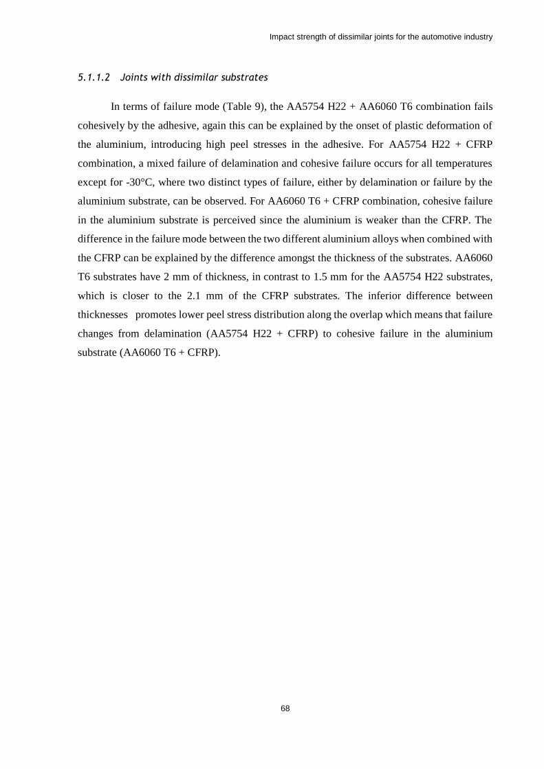
Impact strength of dissimilar joints for the automotive industry
68
5.1.1.2 Joints with dissimilar substrates
In terms of failure mode (Table 9), the AA5754 H22 + AA6060 T6 combination fails
cohesively by the adhesive, again this can be explained by the onset of plastic deformation of
the aluminium, introducing high peel stresses in the adhesive. For AA5754 H22 + CFRP
combination, a mixed failure of delamination and cohesive failure occurs for all temperatures
except for -30°C, where two distinct types of failure, either by delamination or failure by the
aluminium substrate, can be observed. For AA6060 T6 + CFRP combination, cohesive failure
in the aluminium substrate is perceived since the aluminium is weaker than the CFRP. The
difference in the failure mode between the two different aluminium alloys when combined with
the CFRP can be explained by the difference amongst the thickness of the substrates. AA6060
T6 substrates have 2 mm of thickness, in contrast to 1.5 mm for the AA5754 H22 substrates,
which is closer to the 2.1 mm of the CFRP substrates. The inferior difference between
thicknesses promotes lower peel stress distribution along the overlap which means that failure
changes from delamination (AA5754 H22 + CFRP) to cohesive failure in the aluminium
substrate (AA6060 T6 + CFRP).
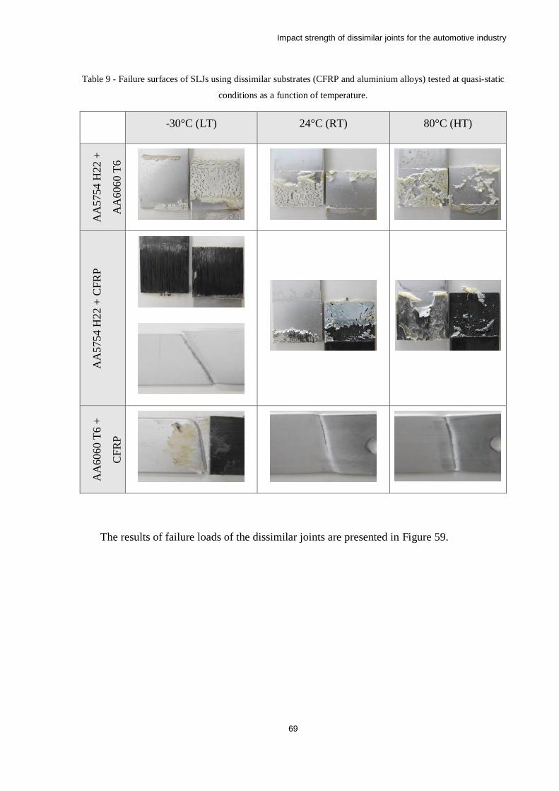
Impact strength of dissimilar joints for the automotive industry
69
Table 9 - Failure surfaces of SLJs using dissimilar substrates (CFRP and aluminium alloys) tested at quasi-static
conditions as a function of temperature.
-30°C (LT) 24°C (RT) 80°C (HT)
AA
5754 H
22 +
AA
6060 T
6
AA
5754
H22
+ C
FR
P
AA
6060
T6 +
CF
RP
The results of failure loads of the dissimilar joints are presented in Figure 59.
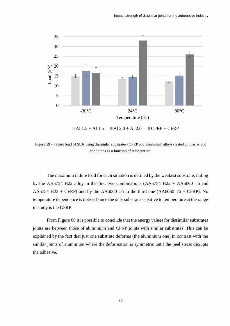
Impact strength of dissimilar joints for the automotive industry
70
Figure 59 - Failure load of SLJs using dissimilar substrates (CFRP and aluminium alloys) tested at quasi-static
conditions as a function of temperature.
The maximum failure load for each situation is defined by the weakest substrate, failing
by the AA5754 H22 alloy in the first two combinations (AA5754 H22 + AA6060 T6 and
AA5754 H22 + CFRP) and by the AA6060 T6 in the third one (AA6060 T6 + CFRP). No
temperature dependence is noticed since the only substrate sensitive to temperature at the range
in study is the CFRP.
From Figure 60 it is possible to conclude that the energy values for dissimilar substrates
joints are between those of aluminium and CFRP joints with similar substrates. This can be
explained by the fact that just one substrate deforms (the aluminium one) in contrast with the
similar joints of aluminium where the deformation is symmetric until the peel stress disrupts
the adhesive.
0
5
10
15
20
25
30
35
30°C 24°C 80°C
Load
(kN
)
Temperature (°C)
Al 1.5 + Al 1.5 Al 2.0 + Al 2.0 CFRP + CFRP
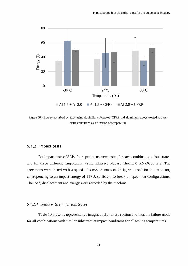
Impact strength of dissimilar joints for the automotive industry
71
Figure 60 - Energy absorbed by SLJs using dissimilar substrates (CFRP and aluminium alloys) tested at quasi-
static conditions as a function of temperature.
5.1.2 Impact tests
For impact tests of SLJs, four specimens were tested for each combination of substrates
and for three different temperature, using adhesive Nagase-ChemteX XNR6852 E-3. The
specimens were tested with a speed of 3 m/s. A mass of 26 kg was used for the impactor,
corresponding to an impact energy of 117 J, sufficient to break all specimen configurations.
The load, displacement and energy were recorded by the machine.
5.1.2.1 Joints with similar substrates
Table 10 presents representative images of the failure section and thus the failure mode
for all combinations with similar substrates at impact conditions for all testing temperatures.
0
20
40
60
80
30°C 24°C 80°C
Ener
gy (
J)
Temperature (°C)
Al 1.5 + Al 2.0 Al 1.5 + CFRP Al 2.0 + CFRP
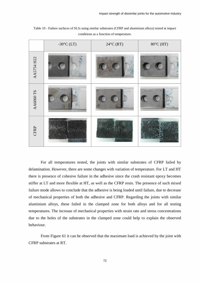
Impact strength of dissimilar joints for the automotive industry
72
Table 10 - Failure surfaces of SLJs using similar substrates (CFRP and aluminium alloys) tested at impact
conditions as a function of temperature.
-30°C (LT) 24°C (RT) 80°C (HT)
AA
5754 H
22
AA
6060
T6
CF
RP
For all temperatures tested, the joints with similar substrates of CFRP failed by
delamination. However, there are some changes with variation of temperature. For LT and HT
there is presence of cohesive failure in the adhesive since the crash resistant epoxy becomes
stiffer at LT and more flexible at HT, as well as the CFRP resin. The presence of such mixed
failure mode allows to conclude that the adhesive is being loaded until failure, due to decrease
of mechanical properties of both the adhesive and CFRP. Regarding the joints with similar
aluminium alloys, these failed in the clamped zone for both alloys and for all testing
temperatures. The increase of mechanical properties with strain rate and stress concentrations
due to the holes of the substrates in the clamped zone could help to explain the observed
behaviour.
From Figure 61 it can be observed that the maximum load is achieved by the joint with
CFRP substrates at RT.

Impact strength of dissimilar joints for the automotive industry
73
Figure 61 - Failure load of SLJs using similar substrates (CFRP and aluminium alloys) tested at impact
conditions as a function of temperature.
Although the adhesive becomes more flexible, reducing the peel loads in SLJs of CFRP
substrates for HT, the proximity to the Tg also leads to lower tensile and shear strength, even
when considering strain rate dependency. It is the occurrence of a mixed failure mode, with
simultaneous delamination and cohesive failure that leads to the lower failure loads. At LT both
the adhesive and the CFRP resin become more brittle. Because the joints with AA6060T6
substrates display a higher failure load than the ones with CFRP substrates it is safe to say that
LT affects the CFRP resin more significantly.
For SLJs with AA6060 T6 substrates, despite a noticeable decrease from LT to RT in
the average value of maximum load, no tendency can be considered since these values fall under
the respective standard deviations. The same behaviour can be observed in SLJs with substrates
made from AA5754 H22 aluminium alloy.
Figure 62 presents the value of energy absorbed for all combinations with similar
substrates at impact conditions for all testing temperatures.
0
5
10
15
20
25
30
35
30°C 24°C 80°C
Load
(k
N)
Temperature (°C)
Al 1.5 + Al 1.5 Al 2.0 + Al 2.0 CFRP + CFRP
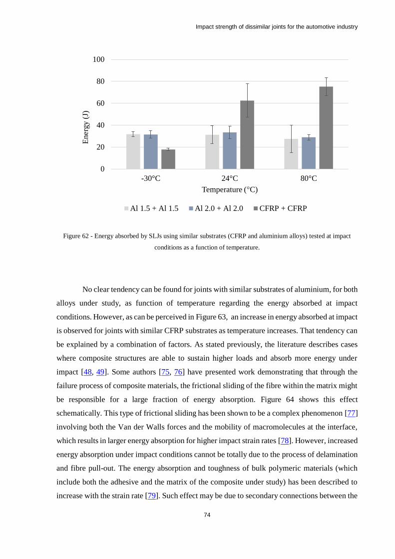
Impact strength of dissimilar joints for the automotive industry
74
Figure 62 - Energy absorbed by SLJs using similar substrates (CFRP and aluminium alloys) tested at impact
conditions as a function of temperature.
No clear tendency can be found for joints with similar substrates of aluminium, for both
alloys under study, as function of temperature regarding the energy absorbed at impact
conditions. However, as can be perceived in Figure 63, an increase in energy absorbed at impact
is observed for joints with similar CFRP substrates as temperature increases. That tendency can
be explained by a combination of factors. As stated previously, the literature describes cases
where composite structures are able to sustain higher loads and absorb more energy under
impact [48, 49]. Some authors [75, 76] have presented work demonstrating that through the
failure process of composite materials, the frictional sliding of the fibre within the matrix might
be responsible for a large fraction of energy absorption. Figure 64 shows this effect
schematically. This type of frictional sliding has been shown to be a complex phenomenon [77]
involving both the Van der Walls forces and the mobility of macromolecules at the interface,
which results in larger energy absorption for higher impact strain rates [78]. However, increased
energy absorption under impact conditions cannot be totally due to the process of delamination
and fibre pull-out. The energy absorption and toughness of bulk polymeric materials (which
include both the adhesive and the matrix of the composite under study) has been described to
increase with the strain rate [79]. Such effect may be due to secondary connections between the
0
20
40
60
80
100
30°C 24°C 80°C
Ener
gy (
J)
Temperature (°C)
Al 1.5 + Al 1.5 Al 2.0 + Al 2.0 CFRP + CFRP
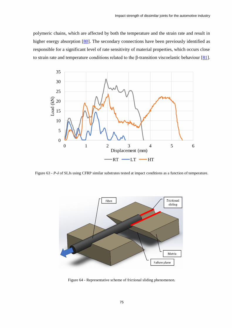
Impact strength of dissimilar joints for the automotive industry
75
polymeric chains, which are affected by both the temperature and the strain rate and result in
higher energy absorption [80]. The secondary connections have been previously identified as
responsible for a significant level of rate sensitivity of material properties, which occurs close
to strain rate and temperature conditions related to the β-transition viscoelastic behaviour [81].
Figure 63 - P-δ of SLJs using CFRP similar substrates tested at impact conditions as a function of temperature.
Figure 64 - Representative scheme of frictional sliding phenomenon.
0
5
10
15
20
25
30
35
0 1 2 3 4 5 6
Load
(kN
)
Displacement (mm)
RT LT HT
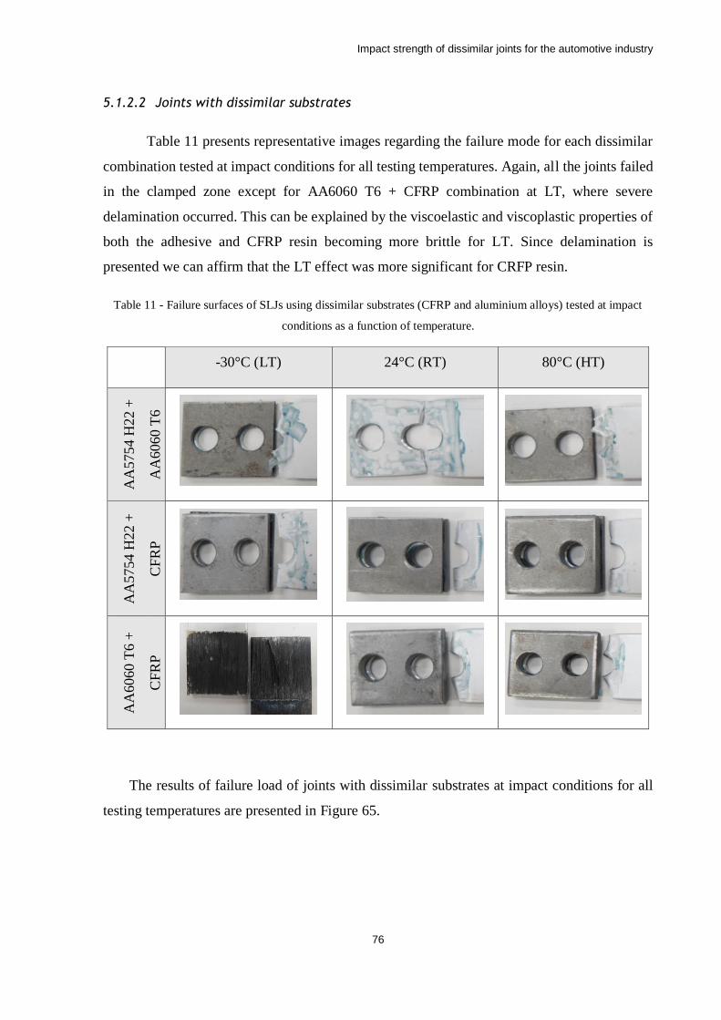
Impact strength of dissimilar joints for the automotive industry
76
5.1.2.2 Joints with dissimilar substrates
Table 11 presents representative images regarding the failure mode for each dissimilar
combination tested at impact conditions for all testing temperatures. Again, all the joints failed
in the clamped zone except for AA6060 T6 + CFRP combination at LT, where severe
delamination occurred. This can be explained by the viscoelastic and viscoplastic properties of
both the adhesive and CFRP resin becoming more brittle for LT. Since delamination is
presented we can affirm that the LT effect was more significant for CRFP resin.
Table 11 - Failure surfaces of SLJs using dissimilar substrates (CFRP and aluminium alloys) tested at impact
conditions as a function of temperature.
-30°C (LT) 24°C (RT) 80°C (HT)
AA
5754 H
22 +
AA
6060
T6
AA
5754
H22 +
CF
RP
AA
6060
T6 +
CF
RP
The results of failure load of joints with dissimilar substrates at impact conditions for all
testing temperatures are presented in Figure 65.
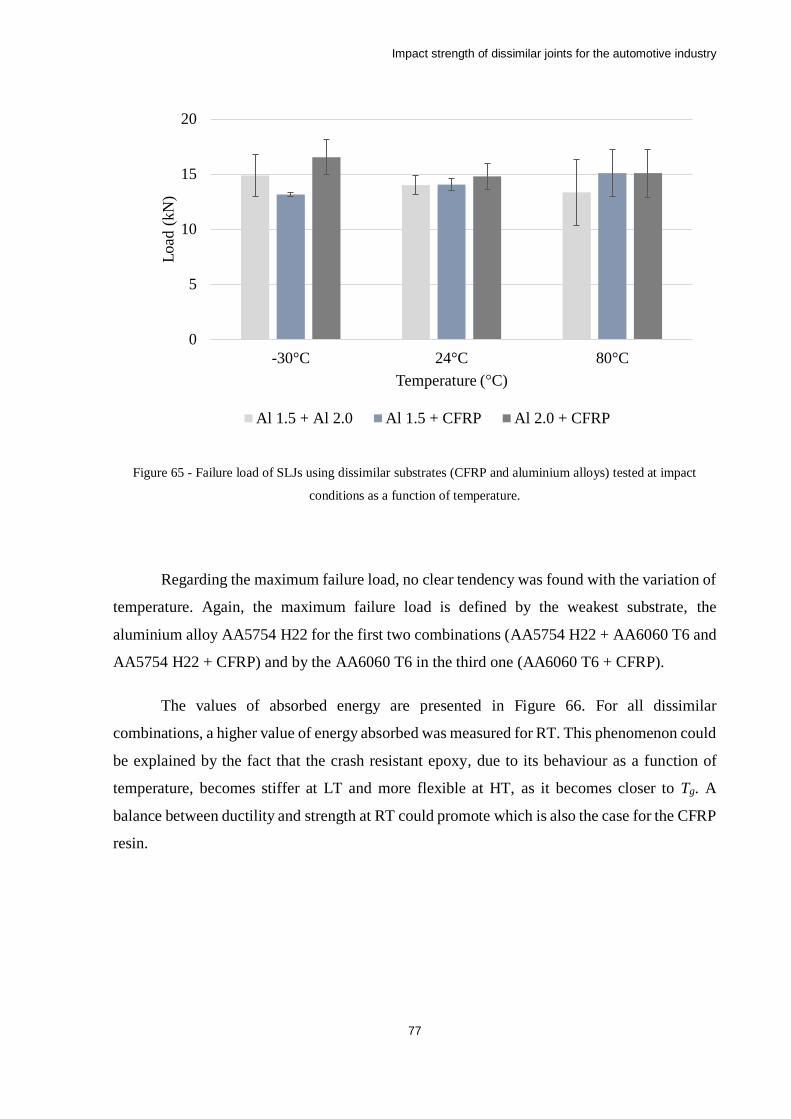
Impact strength of dissimilar joints for the automotive industry
77
Figure 65 - Failure load of SLJs using dissimilar substrates (CFRP and aluminium alloys) tested at impact
conditions as a function of temperature.
Regarding the maximum failure load, no clear tendency was found with the variation of
temperature. Again, the maximum failure load is defined by the weakest substrate, the
aluminium alloy AA5754 H22 for the first two combinations (AA5754 H22 + AA6060 T6 and
AA5754 H22 + CFRP) and by the AA6060 T6 in the third one (AA6060 T6 + CFRP).
The values of absorbed energy are presented in Figure 66. For all dissimilar
combinations, a higher value of energy absorbed was measured for RT. This phenomenon could
be explained by the fact that the crash resistant epoxy, due to its behaviour as a function of
temperature, becomes stiffer at LT and more flexible at HT, as it becomes closer to Tg. A
balance between ductility and strength at RT could promote which is also the case for the CFRP
resin.
0
5
10
15
20
30°C 24°C 80°C
Load
(kN
)
Temperature (°C)
Al 1.5 + Al 2.0 Al 1.5 + CFRP Al 2.0 + CFRP
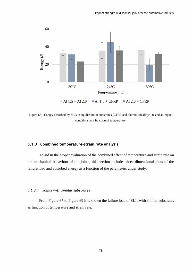
Impact strength of dissimilar joints for the automotive industry
78
Figure 66 - Energy absorbed by SLJs using dissimilar substrates (CFRP and aluminium alloys) tested at impact
conditions as a function of temperature.
5.1.3 Combined temperature-strain rate analysis
To aid in the proper evaluation of the combined effect of temperature and strain rate on
the mechanical behaviour of the joints, this section includes three-dimensional plots of the
failure load and absorbed energy as a function of the parameters under study.
5.1.3.1 Joints with similar substrates
From Figure 67 to Figure 69 it is shown the failure load of SLJs with similar substrates
as function of temperature and strain rate.
0
20
40
60
30°C 24°C 80°C
Ener
gy (
J)
Temperature (°C)
Al 1.5 + Al 2.0 Al 1.5 + CFRP Al 2.0 + CFRP

Impact strength of dissimilar joints for the automotive industry
79
Figure 67 - Failure load of SLJs with AA5754 H22 similar substrates as function of temperature and strain rate.
Figure 68 - Failure load of SLJs with AA6060 T6 similar substrates as function of temperature and strain rate.
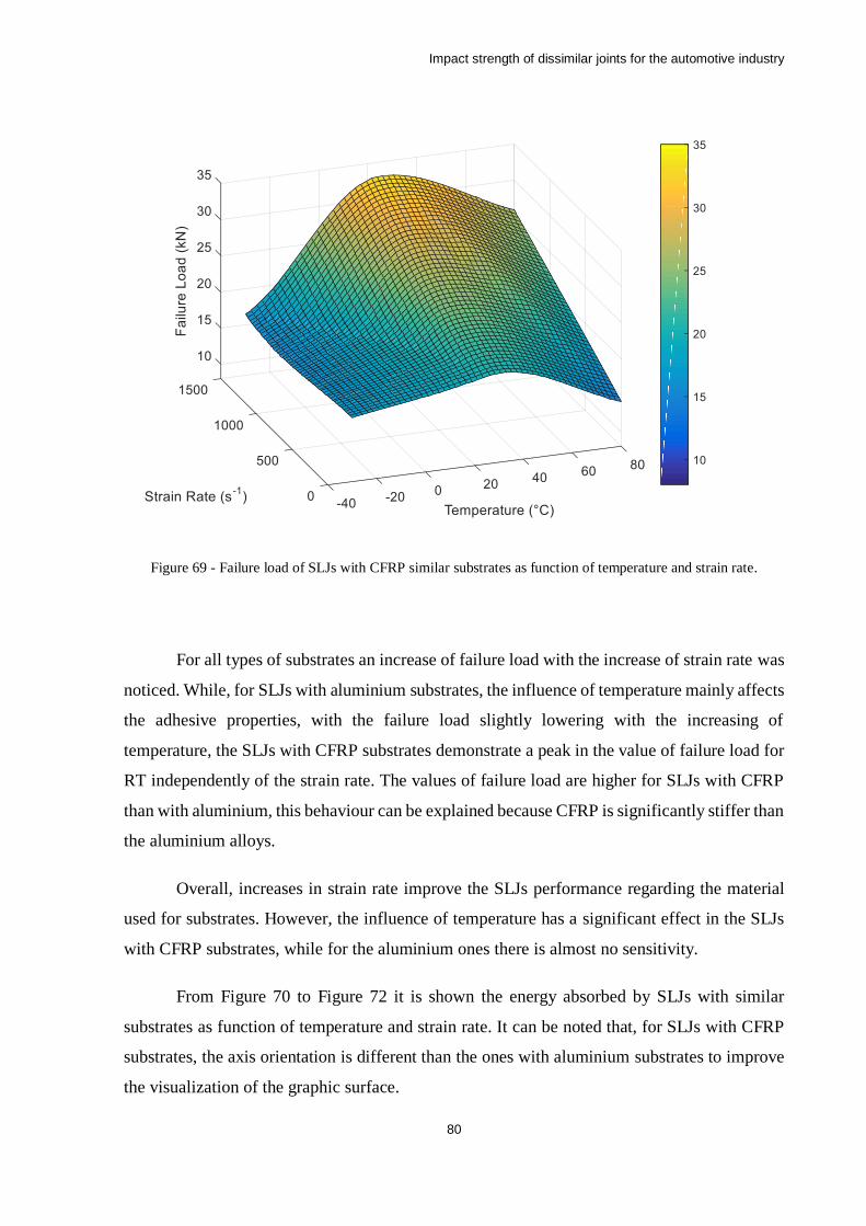
Impact strength of dissimilar joints for the automotive industry
80
Figure 69 - Failure load of SLJs with CFRP similar substrates as function of temperature and strain rate.
For all types of substrates an increase of failure load with the increase of strain rate was
noticed. While, for SLJs with aluminium substrates, the influence of temperature mainly affects
the adhesive properties, with the failure load slightly lowering with the increasing of
temperature, the SLJs with CFRP substrates demonstrate a peak in the value of failure load for
RT independently of the strain rate. The values of failure load are higher for SLJs with CFRP
than with aluminium, this behaviour can be explained because CFRP is significantly stiffer than
the aluminium alloys.
Overall, increases in strain rate improve the SLJs performance regarding the material
used for substrates. However, the influence of temperature has a significant effect in the SLJs
with CFRP substrates, while for the aluminium ones there is almost no sensitivity.
From Figure 70 to Figure 72 it is shown the energy absorbed by SLJs with similar
substrates as function of temperature and strain rate. It can be noted that, for SLJs with CFRP
substrates, the axis orientation is different than the ones with aluminium substrates to improve
the visualization of the graphic surface.
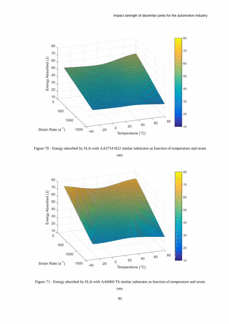
Impact strength of dissimilar joints for the automotive industry
81
Figure 70 - Energy absorbed by SLJs with AA5754 H22 similar substrates as function of temperature and strain
rate.
Figure 71 - Energy absorbed by SLJs with AA6060 T6 similar substrates as function of temperature and strain
rate.
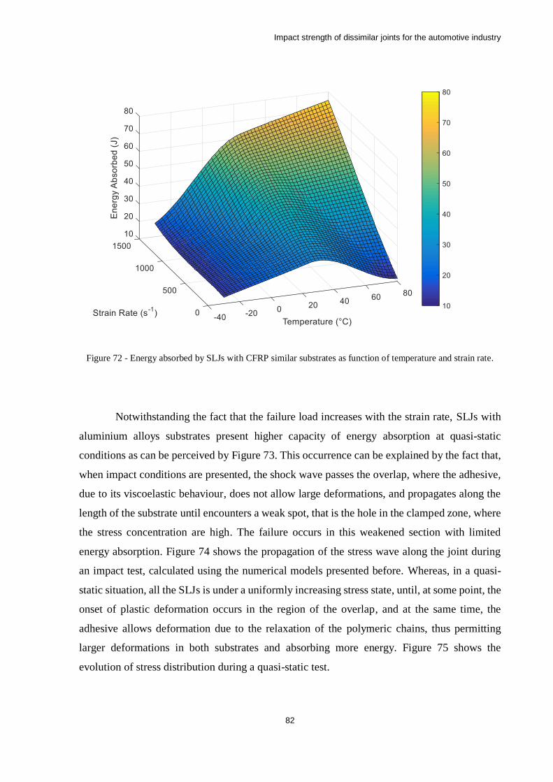
Impact strength of dissimilar joints for the automotive industry
82
Figure 72 - Energy absorbed by SLJs with CFRP similar substrates as function of temperature and strain rate.
Notwithstanding the fact that the failure load increases with the strain rate, SLJs with
aluminium alloys substrates present higher capacity of energy absorption at quasi-static
conditions as can be perceived by Figure 73. This occurrence can be explained by the fact that,
when impact conditions are presented, the shock wave passes the overlap, where the adhesive,
due to its viscoelastic behaviour, does not allow large deformations, and propagates along the
length of the substrate until encounters a weak spot, that is the hole in the clamped zone, where
the stress concentration are high. The failure occurs in this weakened section with limited
energy absorption. Figure 74 shows the propagation of the stress wave along the joint during
an impact test, calculated using the numerical models presented before. Whereas, in a quasi-
static situation, all the SLJs is under a uniformly increasing stress state, until, at some point, the
onset of plastic deformation occurs in the region of the overlap, and at the same time, the
adhesive allows deformation due to the relaxation of the polymeric chains, thus permitting
larger deformations in both substrates and absorbing more energy. Figure 75 shows the
evolution of stress distribution during a quasi-static test.
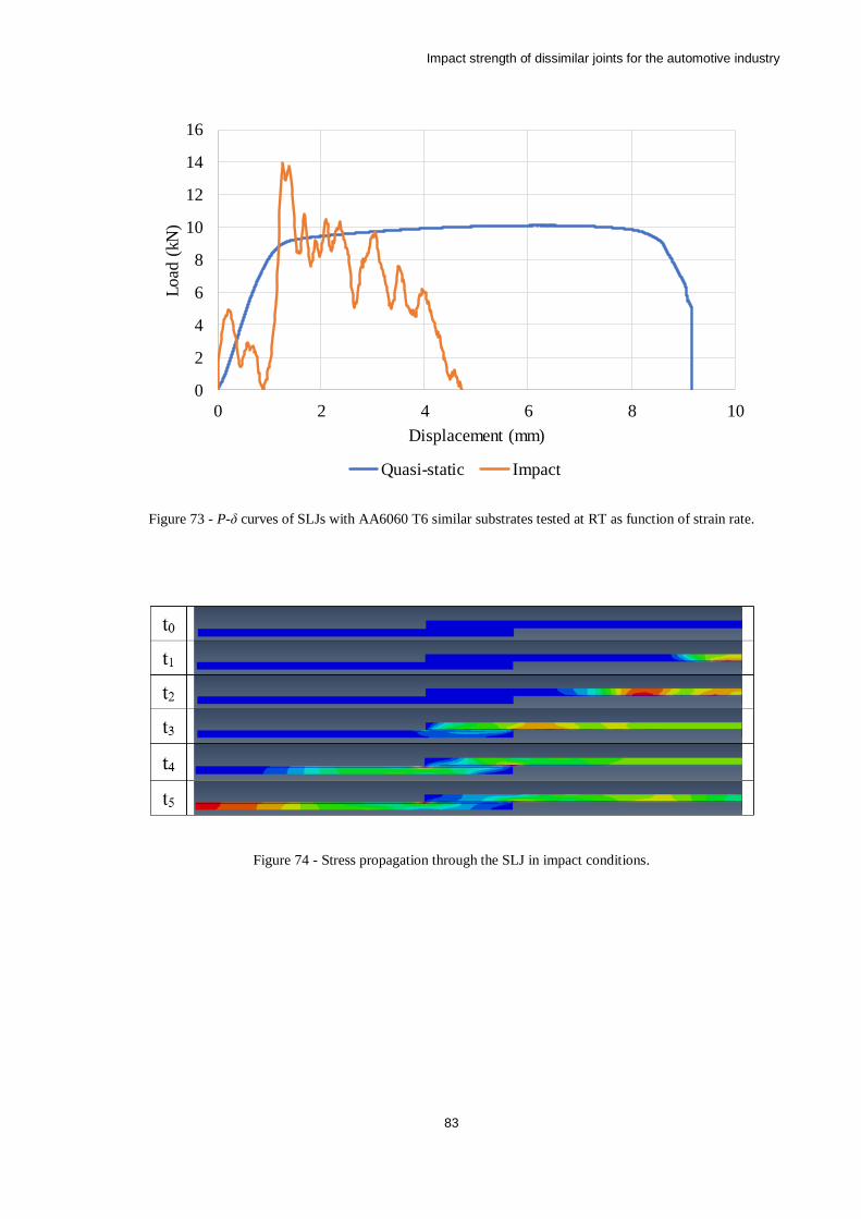
Impact strength of dissimilar joints for the automotive industry
83
Figure 73 - P-δ curves of SLJs with AA6060 T6 similar substrates tested at RT as function of strain rate.
Figure 74 - Stress propagation through the SLJ in impact conditions.
0
2
4
6
8
10
12
14
16
0 2 4 6 8 10
Lo
ad (
kN)
Displacement (mm)
Quasi-static Impact
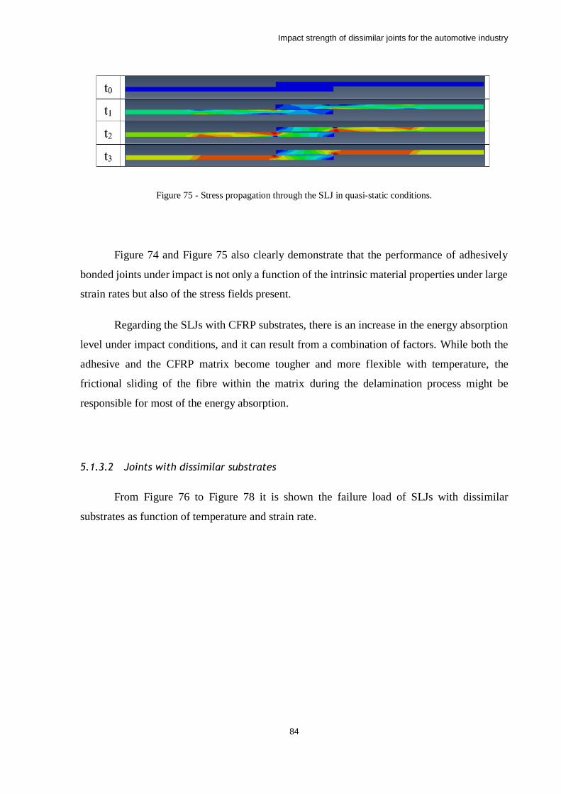
Impact strength of dissimilar joints for the automotive industry
84
Figure 75 - Stress propagation through the SLJ in quasi-static conditions.
Figure 74 and Figure 75 also clearly demonstrate that the performance of adhesively
bonded joints under impact is not only a function of the intrinsic material properties under large
strain rates but also of the stress fields present.
Regarding the SLJs with CFRP substrates, there is an increase in the energy absorption
level under impact conditions, and it can result from a combination of factors. While both the
adhesive and the CFRP matrix become tougher and more flexible with temperature, the
frictional sliding of the fibre within the matrix during the delamination process might be
responsible for most of the energy absorption.
5.1.3.2 Joints with dissimilar substrates
From Figure 76 to Figure 78 it is shown the failure load of SLJs with dissimilar
substrates as function of temperature and strain rate.
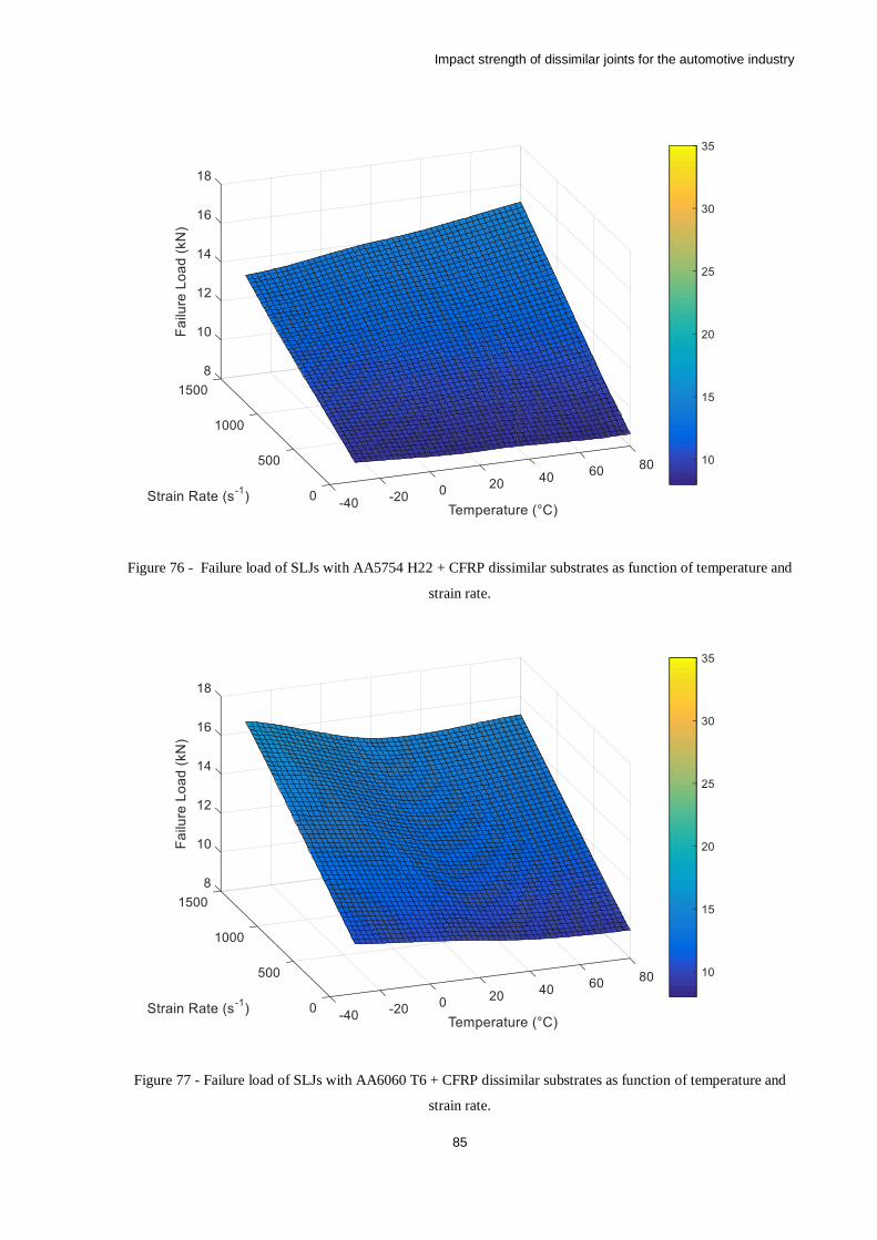
Impact strength of dissimilar joints for the automotive industry
85
Figure 76 - Failure load of SLJs with AA5754 H22 + CFRP dissimilar substrates as function of temperature and
strain rate.
Figure 77 - Failure load of SLJs with AA6060 T6 + CFRP dissimilar substrates as function of temperature and
strain rate.
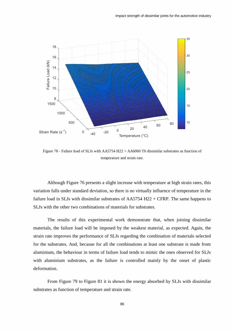
Impact strength of dissimilar joints for the automotive industry
86
Figure 78 - Failure load of SLJs with AA5754 H22 + AA6060 T6 dissimilar substrates as function of
temperature and strain rate.
Although Figure 76 presents a slight increase with temperature at high strain rates, this
variation falls under standard deviation, so there is no virtually influence of temperature in the
failure load in SLJs with dissimilar substrates of AA5754 H22 + CFRP. The same happens to
SLJs with the other two combinations of materials for substrates.
The results of this experimental work demonstrate that, when joining dissimilar
materials, the failure load will be imposed by the weakest material, as expected. Again, the
strain rate improves the performance of SLJs regarding the combination of materials selected
for the substrates. And, because for all the combinations at least one substrate is made from
aluminium, the behaviour in terms of failure load tends to mimic the ones observed for SLJs
with aluminium substrates, as the failure is controlled mainly by the onset of plastic
deformation.
From Figure 79 to Figure 81 it is shown the energy absorbed by SLJs with dissimilar
substrates as function of temperature and strain rate.
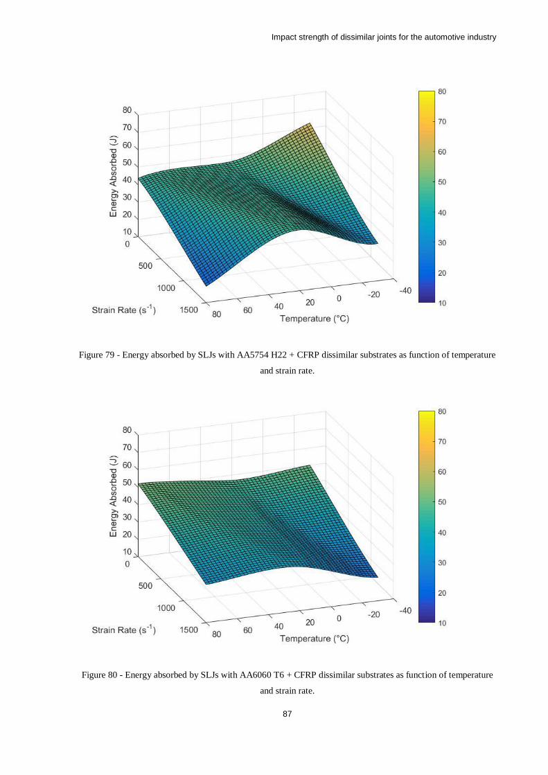
Impact strength of dissimilar joints for the automotive industry
87
Figure 79 - Energy absorbed by SLJs with AA5754 H22 + CFRP dissimilar substrates as function of temperature
and strain rate.
Figure 80 - Energy absorbed by SLJs with AA6060 T6 + CFRP dissimilar substrates as function of temperature
and strain rate.
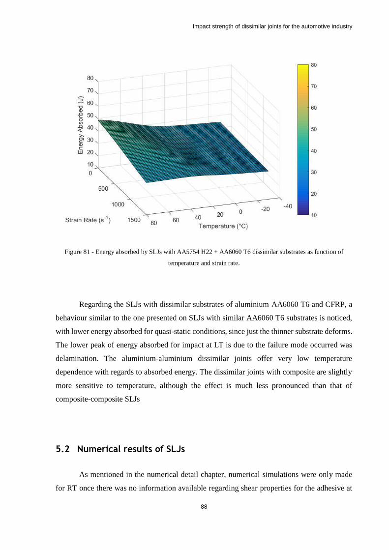
Impact strength of dissimilar joints for the automotive industry
88
Figure 81 - Energy absorbed by SLJs with AA5754 H22 + AA6060 T6 dissimilar substrates as function of
temperature and strain rate.
Regarding the SLJs with dissimilar substrates of aluminium AA6060 T6 and CFRP, a
behaviour similar to the one presented on SLJs with similar AA6060 T6 substrates is noticed,
with lower energy absorbed for quasi-static conditions, since just the thinner substrate deforms.
The lower peak of energy absorbed for impact at LT is due to the failure mode occurred was
delamination. The aluminium-aluminium dissimilar joints offer very low temperature
dependence with regards to absorbed energy. The dissimilar joints with composite are slightly
more sensitive to temperature, although the effect is much less pronounced than that of
composite-composite SLJs
5.2 Numerical results of SLJs
As mentioned in the numerical detail chapter, numerical simulations were only made
for RT once there was no information available regarding shear properties for the adhesive at
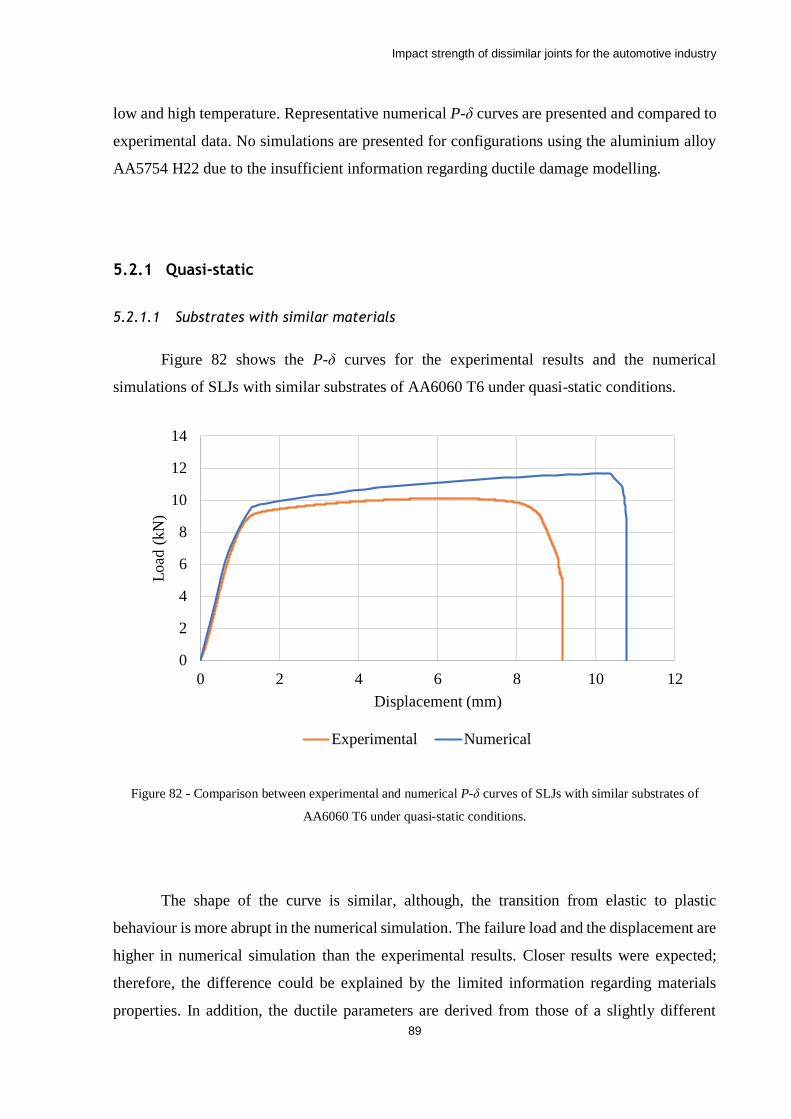
Impact strength of dissimilar joints for the automotive industry
89
low and high temperature. Representative numerical P-δ curves are presented and compared to
experimental data. No simulations are presented for configurations using the aluminium alloy
AA5754 H22 due to the insufficient information regarding ductile damage modelling.
5.2.1 Quasi-static
5.2.1.1 Substrates with similar materials
Figure 82 shows the P-δ curves for the experimental results and the numerical
simulations of SLJs with similar substrates of AA6060 T6 under quasi-static conditions.
Figure 82 - Comparison between experimental and numerical P-δ curves of SLJs with similar substrates of
AA6060 T6 under quasi-static conditions.
The shape of the curve is similar, although, the transition from elastic to plastic
behaviour is more abrupt in the numerical simulation. The failure load and the displacement are
higher in numerical simulation than the experimental results. Closer results were expected;
therefore, the difference could be explained by the limited information regarding materials
properties. In addition, the ductile parameters are derived from those of a slightly different
0
2
4
6
8
10
12
14
0 2 4 6 8 10 12
Load
(kN
)
Displacement (mm)
Experimental Numerical
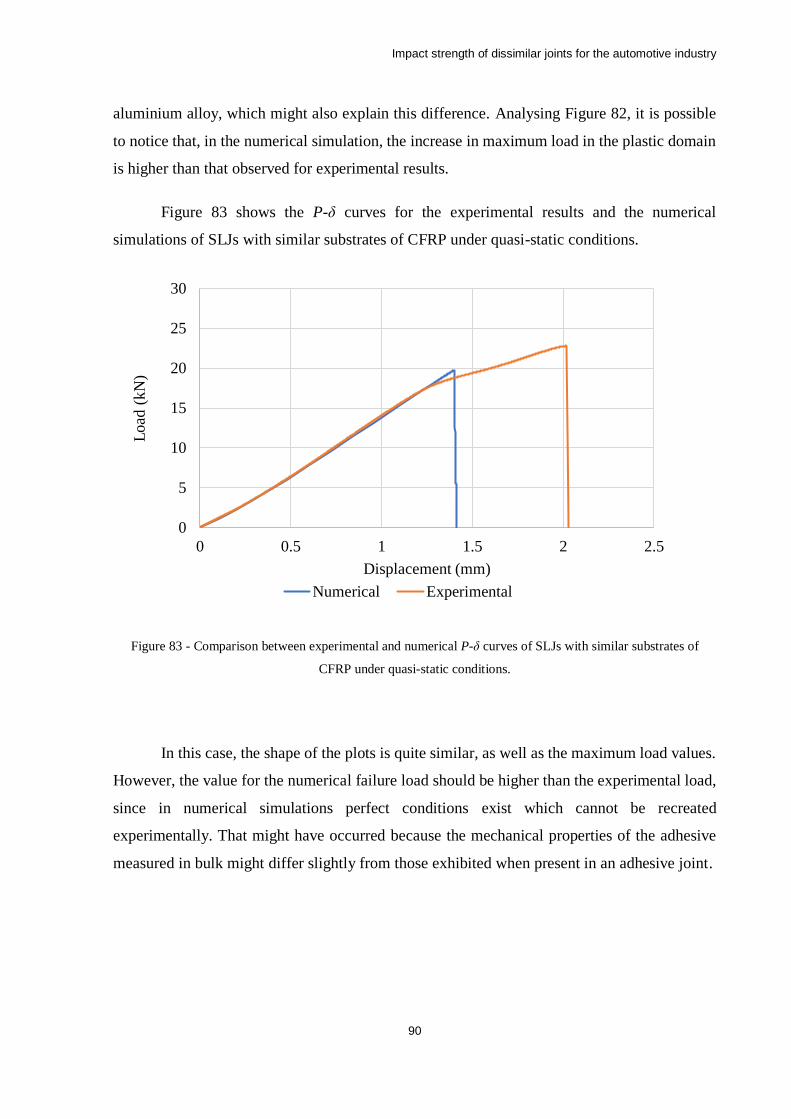
Impact strength of dissimilar joints for the automotive industry
90
aluminium alloy, which might also explain this difference. Analysing Figure 82, it is possible
to notice that, in the numerical simulation, the increase in maximum load in the plastic domain
is higher than that observed for experimental results.
Figure 83 shows the P-δ curves for the experimental results and the numerical
simulations of SLJs with similar substrates of CFRP under quasi-static conditions.
Figure 83 - Comparison between experimental and numerical P-δ curves of SLJs with similar substrates of
CFRP under quasi-static conditions.
In this case, the shape of the plots is quite similar, as well as the maximum load values.
However, the value for the numerical failure load should be higher than the experimental load,
since in numerical simulations perfect conditions exist which cannot be recreated
experimentally. That might have occurred because the mechanical properties of the adhesive
measured in bulk might differ slightly from those exhibited when present in an adhesive joint.
0
5
10
15
20
25
30
0 0.5 1 1.5 2 2.5
Load
(kN
)
Displacement (mm)
Numerical Experimental
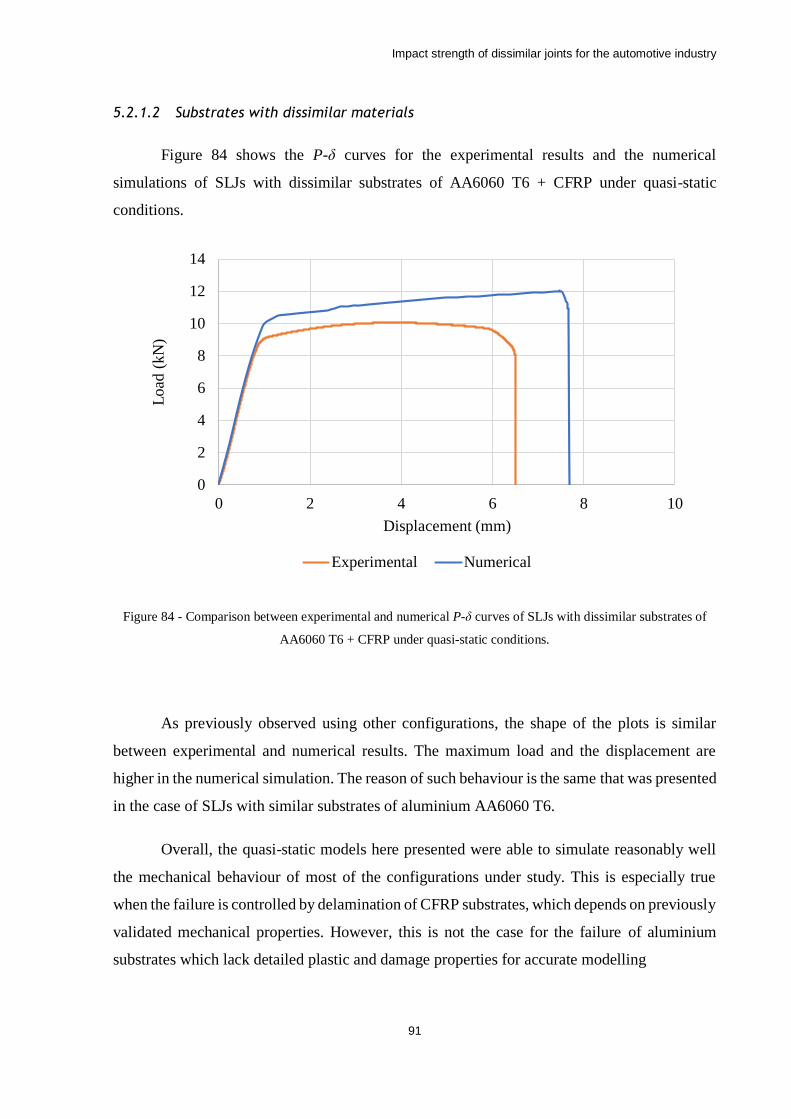
Impact strength of dissimilar joints for the automotive industry
91
5.2.1.2 Substrates with dissimilar materials
Figure 84 shows the P-δ curves for the experimental results and the numerical
simulations of SLJs with dissimilar substrates of AA6060 T6 + CFRP under quasi-static
conditions.
Figure 84 - Comparison between experimental and numerical P-δ curves of SLJs with dissimilar substrates of
AA6060 T6 + CFRP under quasi-static conditions.
As previously observed using other configurations, the shape of the plots is similar
between experimental and numerical results. The maximum load and the displacement are
higher in the numerical simulation. The reason of such behaviour is the same that was presented
in the case of SLJs with similar substrates of aluminium AA6060 T6.
Overall, the quasi-static models here presented were able to simulate reasonably well
the mechanical behaviour of most of the configurations under study. This is especially true
when the failure is controlled by delamination of CFRP substrates, which depends on previously
validated mechanical properties. However, this is not the case for the failure of aluminium
substrates which lack detailed plastic and damage properties for accurate modelling
0
2
4
6
8
10
12
14
0 2 4 6 8 10
Load
(kN
)
Displacement (mm)
Experimental Numerical
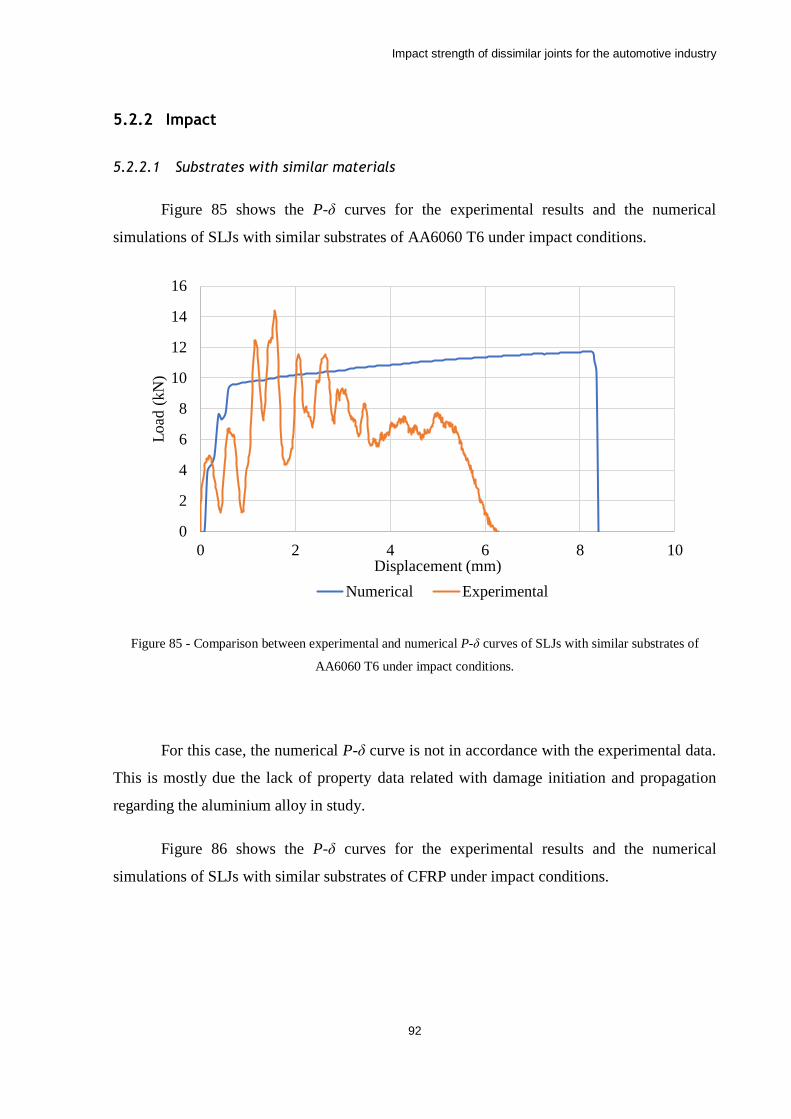
Impact strength of dissimilar joints for the automotive industry
92
5.2.2 Impact
5.2.2.1 Substrates with similar materials
Figure 85 shows the P-δ curves for the experimental results and the numerical
simulations of SLJs with similar substrates of AA6060 T6 under impact conditions.
Figure 85 - Comparison between experimental and numerical P-δ curves of SLJs with similar substrates of
AA6060 T6 under impact conditions.
For this case, the numerical P-δ curve is not in accordance with the experimental data.
This is mostly due the lack of property data related with damage initiation and propagation
regarding the aluminium alloy in study.
Figure 86 shows the P-δ curves for the experimental results and the numerical
simulations of SLJs with similar substrates of CFRP under impact conditions.
0
2
4
6
8
10
12
14
16
0 2 4 6 8 10
Load
(kN
)
Displacement (mm)
Numerical Experimental
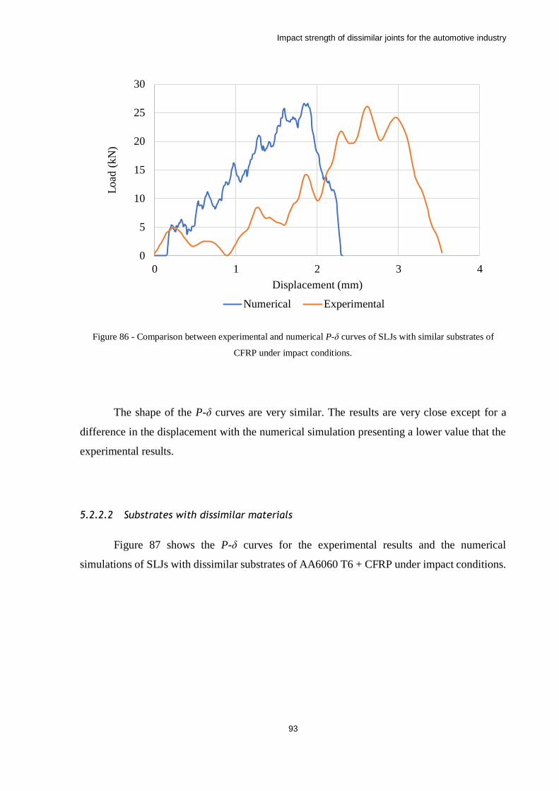
Impact strength of dissimilar joints for the automotive industry
93
Figure 86 - Comparison between experimental and numerical P-δ curves of SLJs with similar substrates of
CFRP under impact conditions.
The shape of the P-δ curves are very similar. The results are very close except for a
difference in the displacement with the numerical simulation presenting a lower value that the
experimental results.
5.2.2.2 Substrates with dissimilar materials
Figure 87 shows the P-δ curves for the experimental results and the numerical
simulations of SLJs with dissimilar substrates of AA6060 T6 + CFRP under impact conditions.
0
5
10
15
20
25
30
0 1 2 3 4
Load
(kN
)
Displacement (mm)
Numerical Experimental
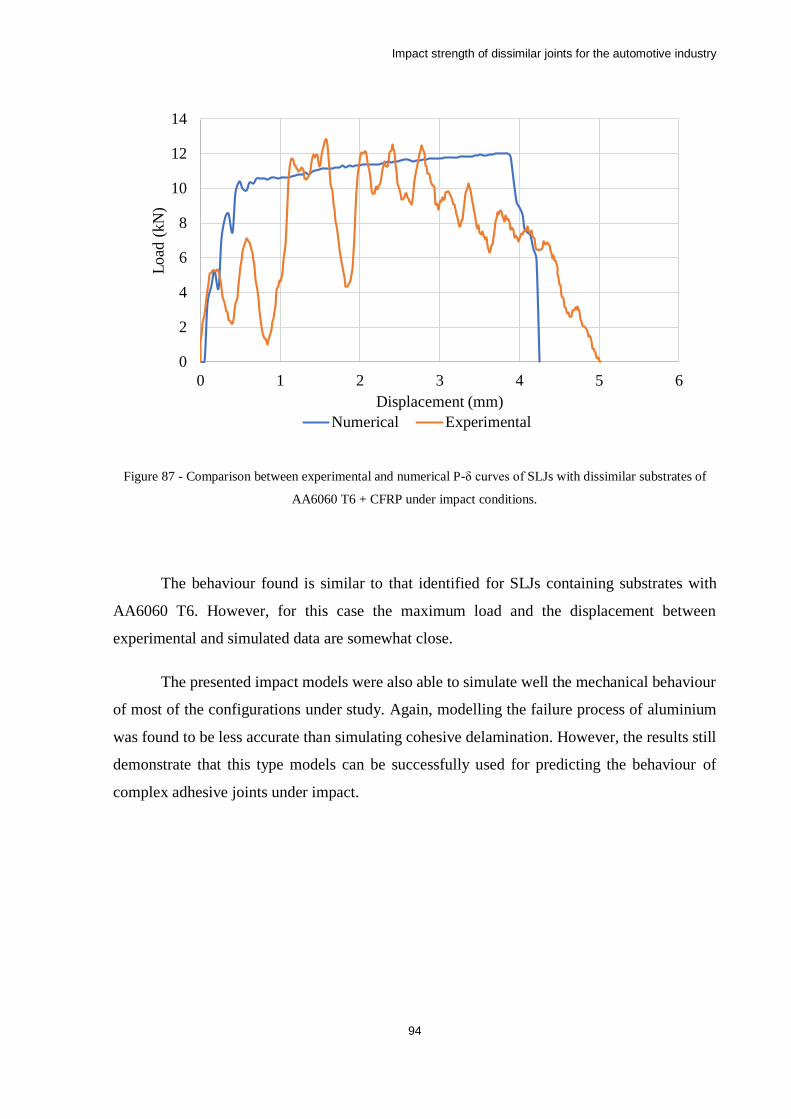
Impact strength of dissimilar joints for the automotive industry
94
Figure 87 - Comparison between experimental and numerical P-δ curves of SLJs with dissimilar substrates of
AA6060 T6 + CFRP under impact conditions.
The behaviour found is similar to that identified for SLJs containing substrates with
AA6060 T6. However, for this case the maximum load and the displacement between
experimental and simulated data are somewhat close.
The presented impact models were also able to simulate well the mechanical behaviour
of most of the configurations under study. Again, modelling the failure process of aluminium
was found to be less accurate than simulating cohesive delamination. However, the results still
demonstrate that this type models can be successfully used for predicting the behaviour of
complex adhesive joints under impact.
0
2
4
6
8
10
12
14
0 1 2 3 4 5 6
Load
(kN
)
Displacement (mm)
Numerical Experimental
Impact strength of dissimilar joints for the automotive industry
95
6 Conclusions
An in-depth analysis of the quasi-static and impact behaviour of dissimilar adhesive
joints subjected to a wide range of temperatures was performed in this work. A list of the
conclusions drawn from this work follows:
• The Young´s modulus and tensile stress of the studied crash-resistant adhesive both
increase with the increase of strain rate and decrease of temperature;
• The fracture energy in mode I (𝑮𝑰𝑪) of the studied crash-resistant adhesive was found
to increase with the increase of strain rate and increase of temperature;
• The CFFR-CFRP joint configuration exhibited the highest failure load for all
conditions except for the impact test at -30°C, where the performance of all joints under
study was similar. The aluminium joints with similar substrates exhibited low
temperature sensitivity and failure loads significantly lower than those exhibited by the
CFRP-CFRP joints.
• The performance of the dissimilar joints (maximum load) was found to be limited by
the aluminium deformation in all conditions tested;
• In quasi-static conditions the aluminium-aluminium similar joints absorbed the most
energy for all temperatures tested due to large level of plastic deformation present. In
impact conditions, the CFRP-CFRP joints were those that absorbed more energy due
to frictional sliding during delamination. At low temperatures this effect is less
pronounced, and the aluminium alloys absorb more energy;
• A significant difference in absorbed energy from static to impact was found when
testing the joints with aluminium substrates. This is due to the fact that failure occurred
in the clamped section during impact testing;
• This work suggests that quasi-static testing and modelling can be used for the impact
strength prediction of joints bonded with crash resistant adhesives. It was verified
experimentally that under impact these joints offer failure loads consistently above
Impact strength of dissimilar joints for the automotive industry
96
those encountered at low strain rates. If the joint is able to sustain a given quasi-static
load, under impact it will always perform better. However, this work does not allow to
extract the same conclusions with regards to energy absorption due to incomplete data,
as under impact the aluminium substrates failed near the clamps with low energy
absorption.
• The effect of temperature on joint performance is only pronounced for the CFRP-CFRP
SLJs, due to the large temperature dependence of these materials as they approach Tg.
As expected, in joints bonded with a crash resistant adhesive and containing aluminium
substrates the effect of temperature is very limited, as the substrate is temperature
insensitive and the adhesive, although losing strength, becomes tougher.
• The quasi-static models using cohesive zone modelling were able to simulate
reasonably well the mechanical behaviour of most of the configurations under study,
especially when predicting the failure of CFRP substrates. However, given the limited
property data, proper modelling of the aluminium failure process was not possible.
• The impact models developed during this work were also able to simulate reasonably
well the mechanical behaviour of most of the configurations under study. Again, the
failure process of CFRP materials was found to be more accurately modelled that then
the failure process of aluminium.
As a final remark, it is possible to conclude that dissimilar adhesive joints, if used in
conjunction with modern crash resistant adhesives, can effectively be used for the construction
of automotive structures, without significant sacrifices in joint performance, including energy
absorption under impact. Moreover, their performance can also be simulated using advanced
cohesive zone models minimizing the need to perform extensive experimental testing.
Impact strength of dissimilar joints for the automotive industry
97
7 Future works
Due to the complexity of the impact phenomena, there are many experimental
procedures that can be performed to further explore the behaviour of the adhesive joints when
subjected to high strain rates. A few ideas are listed in this section:
• Due to the difficulties found in modelling the mechanical behaviour of the SLJs with
aluminium substrates, an important complementary work could consist in a detailed
characterisation of the aluminium substrates, especially their plastic behaviour and
ductile damage mechanisms. This would allow to more accurately predict the joint
failure loads and the displacement at failure.
• As the failure of the joints was mostly by delamination, the use of techniques that
mitigate this type of failure should also be explored. Usage of fibre metal laminates or
geometrical modifications that reduce the peel stresses in the composite are of special
interest.
• Experiments with alternative substrates geometries and mechanical properties to
balance the stiffness of the joint. By adjusting the substrates, it might be possible to
improve significantly the performance of the joints, especially under impact conditions.
• The use of mixed adhesives could be explored also in attempt to improve the stress
distribution of the joint, reducing peel loads both on the composite and the aluminium
substrates.
• To further validate the results and procedures described in this thesis, it would be
interesting to perform testing on component scale specimens, with geometries closely
resembling that of a finished automotive component.
Impact strength of dissimilar joints for the automotive industry
98
References
[1] L. F. M. da Silva, A. Öchsner, and R. D. Adams, Handbook of Adhesion Technology.
Springer Berlin Heidelberg, 2011.
[2] R. D. Adams and W. C. Wake, Structural Adhesive Joints in Engineering. Elsevier
Applied Science Publishers, 1984.
[3] E. Petrie, Handbook of Adhesives and Sealants. McGraw-Hill Education, 2007.
[4] R. D. Adams, Adhesive Bonding: Science, Technology, and Applications. Taylor &
Francis, 2005.
[5] A. J. Kinloch, Adhesion and Adhesives: Science and Technology. Springer, 1987.
[6] W. Lees, Adhesives in engineering design. Springer, 1984.
[7] M. D. Banea and L. F. M. d. Silva, "Adhesively bonded joints in composite materials:
An overview," Proceedings of the Institution of Mechanical Engineers, Part L: Journal
of Materials: Design and Applications, vol. 223, no. 1, pp. 1-18, 2009.
[8] R. Adams and J. Harris, "A critical assessment of the block impact test for measuring
the impact strength of adhesive bonds," International Journal of Adhesion and
Adhesives, vol. 16, no. 2, pp. 61-71, 1996.
[9] A. B. Strong, Fundamentals of composites manufacturing: materials, methods and
applications. Society of Manufacturing Engineers, 2008.
[10] K. Sears, "Automotive engineering: strategic overview," Steel World, vol. 2, no. 1, pp.
55-68, 1997.
[11] W. Miller, L. Zhuang, J. Bottema, A. J. Wittebrood, P. De Smet, A. Haszler, and A.
Vieregge, "Recent development in aluminium alloys for the automotive industry,"
Materials Science and Engineering: A, vol. 280, no. 1, pp. 37-49, 2000.
[12] U. Lindholm, "Some experiments with the split hopkinson pressure bar∗," Journal of
the Mechanics and Physics of Solids, vol. 12, no. 5, pp. 317-335, 1964.
[13] J. Bouchet, E. Jacquelin, and P. Hamelin, "Static and dynamic behavior of combined
composite aluminium tube for automotive applications," Composites science and
technology, vol. 60, no. 10, pp. 1891-1900, 2000.
[14] J. Harding and L. M. Welsh, "A tensile testing technique for fibre-reinforced composites
at impact rates of strain," Journal of Materials Science, vol. 18, no. 6, pp. 1810-1826,
1983.
[15] L. F. Da Silva and R. Adams, "Techniques to reduce the peel stresses in adhesive joints
with composites," International Journal of Adhesion and Adhesives, vol. 27, no. 3, pp.
227-235, 2007.
[16] A. Kelly, Concise encyclopedia of composite materials. Elsevier, 2012.
[17] F. L. Matthews and R. D. Rawlings, Composite materials: engineering and science.
Elsevier, 1999.
[18] U. Meier, "Carbon fiber-reinforced polymers: modern materials in bridge engineering,"
Structural Engineering International, vol. 2, no. 1, pp. 7-12, 1992.
Impact strength of dissimilar joints for the automotive industry
99
[19] R. Mohmmed, A. Ahmed, M. A. Elgalib, and H. Ali, "Low Velocity Impact Properties
of Foam Sandwich Composites: A Brief Review," College of Textiles Engineering,
Sudan University of Science and Technology, Sudan, 2014.
[20] W. Knauss and L. Gonzalez, "Global Failure Modes in Composite Structures," NASA
Grant NAG 1-1975, 2001.
[21] M. Laffan, S. Pinho, P. Robinson, and A. McMillan, "Translaminar fracture toughness
testing of composites: a review," Polymer testing, vol. 31, no. 3, pp. 481-489, 2012.
[22] L. F. Da Silva and R. Adams, "Adhesive joints at high and low temperatures using
similar and dissimilar adherends and dual adhesives," International Journal of Adhesion
and Adhesives, vol. 27, no. 3, pp. 216-226, 2007.
[23] A. Deb, I. Malvade, P. Biswas, and J. Schroeder, "An experimental and analytical study
of the mechanical behaviour of adhesively bonded joints for variable extension rates
and temperatures," International journal of adhesion and adhesives, vol. 28, no. 1, pp.
1-15, 2008.
[24] J. J. M. Machado, E. A. S. Marques, and L. F. M. da Silva, "Adhesives and adhesive
joints under impact loadings: An overview," The Journal of Adhesion, pp. 1-32, 2017.
[25] J. Harris and R. Adams, "An assessment of the impact performance of bonded joints for
use in high energy absorbing structures," Proceedings of the Institution of Mechanical
Engineers, Part C: Journal of Mechanical Engineering Science, vol. 199, no. 2, pp.
121-131, 1985.
[26] G. Sharon, H. Dodiuk, and S. Kenig, "Effects of loading rate and temperature on the
mechanical properties of structural adhesives containing a carrier," The Journal of
Adhesion, vol. 31, no. 1, pp. 21-31, 1989.
[27] M. Banea, F. De Sousa, L. Da Silva, R. Campilho, and A. B. de Pereira, "Effects of
temperature and loading rate on the mechanical properties of a high temperature epoxy
adhesive," Journal of Adhesion Science and Technology, vol. 25, no. 18, pp. 2461-2474,
2011.
[28] D. Holt, "The strain-rate dependence of the flow stress in some aluminum alloys,"
Trans. ASM, vol. 60, pp. 152-159, 1967.
[29] K. Tanaka and T. Nojima, "Strain rate change tests of aluminium alloys under high
strain rate," in Proceedings of the 19th Japan congress on materials research, 1975, pp.
48-51.
[30] U. Lindholm, R. Bessey, and G. Smith, "Effect of strain rate on yield strength, tensile
strength and elongation of three aluminum alloys," J MATER, vol. 6, no. 1, pp. 119-133,
1971.
[31] A. H. Clausen, T. Børvik, O. S. Hopperstad, and A. Benallal, "Flow and fracture
characteristics of aluminium alloy AA5083–H116 as function of strain rate, temperature
and triaxiality," Materials Science and Engineering: A, vol. 364, no. 1, pp. 260-272,
2004.
[32] M. Abbadi, P. Hähner, and A. Zeghloul, "On the characteristics of Portevin–Le
Chatelier bands in aluminum alloy 5182 under stress-controlled and strain-controlled
tensile testing," Materials Science and Engineering: A, vol. 337, no. 1, pp. 194-201,
2002.
Impact strength of dissimilar joints for the automotive industry
100
[33] T. Naka and F. Yoshida, "Deep drawability of type 5083 aluminium–magnesium alloy
sheet under various conditions of temperature and forming speed," Journal of Materials
Processing Technology, vol. 89, pp. 19-23, 1999.
[34] L. D. Oosterkamp, A. Ivankovic, and G. Venizelos, "High strain rate properties of
selected aluminium alloys," Materials Science and Engineering: A, vol. 278, no. 1, pp.
225-235, 2000.
[35] R. Smerd, S. Winkler, C. Salisbury, M. Worswick, D. Lloyd, and M. Finn, "High strain
rate tensile testing of automotive aluminum alloy sheet," International Journal of
Impact Engineering, vol. 32, no. 1, pp. 541-560, 2005.
[36] Y. Chen, A. Clausen, O. Hopperstad, and M. Langseth, "Stress–strain behaviour of
aluminium alloys at a wide range of strain rates," International Journal of Solids and
Structures, vol. 46, no. 21, pp. 3825-3835, 2009.
[37] N. Taniguchi, T. Nishiwaki, and H. Kawada, "Tensile strength of unidirectional CFRP
laminate under high strain rate," Advanced Composite Materials, vol. 16, no. 2, pp. 167-
180, 2007.
[38] J. Hou and C. Ruiz, "Measurement of the properties of woven CFRP T300/914 at
different strain rates," Composites Science and Technology, vol. 60, no. 15, pp. 2829-
2834, 2000.
[39] T. Gomez-del Rio, E. Barbero, R. Zaera, and C. Navarro, "Dynamic tensile behaviour
at low temperature of CFRP using a split Hopkinson pressure bar," Composites Science
and Technology, vol. 65, no. 1, pp. 61-71, 2005.
[40] J. Machado, E. Marques, R. Campilho, and L. F. da Silva, "Mode I fracture toughness
of CFRP as a function of temperature and strain rate," Journal of Composite Materials,
vol. 51, no. 23, pp. 3315-3326, 2017.
[41] J. Machado, E. Marques, R. Campilho, and L. F. da Silva, "Mode II fracture toughness
of CFRP as a function of temperature and strain rate," Composites Part B: Engineering,
vol. 114, pp. 311-318, 2017.
[42] G. C. Jacob, J. F. Fellers, S. Simunovic, and J. M. Starbuck, "Energy absorption in
polymer composites for automotive crashworthiness," Journal of composite materials,
vol. 36, no. 7, pp. 813-850, 2002.
[43] S. Ramakrishna, "Energy absorption characteristics of knitted fabric reinforced epoxy
composite tubes," Journal of reinforced plastics and composites, vol. 14, no. 10, pp.
1121-1141, 1995.
[44] A. G. Mamalis, Y. B. Yuan, and G. Viegelahn, "Collapse of thin–wall composite
sections subjected to high speed axial loading," International journal of vehicle design,
vol. 13, no. 5-6, pp. 564-579, 1992.
[45] D. Schmueser and L. Wickliffe, "Impact energy absorption of continuous fiber
composite tubes," Journal of engineering materials and technology, vol. 109, no. 1, pp.
72-77, 1987.
[46] G. L. Farley, "Energy absorption of composite materials," Journal of composite
Materials, vol. 17, no. 3, pp. 267-279, 1983.
[47] P. Thornton, "Energy absorption in composite structures," Journal of Composite
Materials, vol. 13, no. 3, pp. 247-262, 1979.
Impact strength of dissimilar joints for the automotive industry
101
[48] P. Thornton, "The crush behavior of pultruded tubes at high strain rates," Journal of
Composite Materials, vol. 24, no. 6, pp. 594-615, 1990.
[49] G. L. Farley, "The effects of crushing speed on the energy-absorption capability of
composite tubes," Journal of Composite Materials, vol. 25, no. 10, pp. 1314-1329, 1991.
[50] G. R. Wooley and D. R. Carver, Stress concentration factors for bonded lap joints.
Louisiana State University and Agricultural and Mechanical College. Division of
Engineering Research, 1971.
[51] R. Adams and N. Peppiatt, "Stress analysis of adhesive-bonded lap joints," Journal of
strain analysis, vol. 9, no. 3, pp. 185-196, 1974.
[52] A. A. Griffith and M. Eng, "VI. The phenomena of rupture and flow in solids," Phil.
Trans. R. Soc. Lond. A, vol. 221, no. 582-593, pp. 163-198, 1921.
[53] G. Barenblatt, "Equilibrium cracks formed on a brittle fracture," Doklady Akademii
Nauk Sssr, vol. 127, no. 1, pp. 47-50, 1959.
[54] A. Hillerborg, M. Modéer, and P.-E. Petersson, "Analysis of crack formation and crack
growth in concrete by means of fracture mechanics and finite elements," Cement and
concrete research, vol. 6, no. 6, pp. 773-781, 1976.
[55] H. Khoramishad, A. Crocombe, K. Katnam, and I. Ashcroft, "Predicting fatigue damage
in adhesively bonded joints using a cohesive zone model," International Journal of
fatigue, vol. 32, no. 7, pp. 1146-1158, 2010.
[56] J. Gonçalves, M. De Moura, P. De Castro, and A. Marques, "Interface element including
point-to-surface constraints for three-dimensional problems with damage propagation,"
Engineering Computations, vol. 17, no. 1, pp. 28-47, 2000.
[57] M. De Moura, J. Gonçalves, A. Marques, and P. De Castro, "Prediction of compressive
strength of carbon–epoxy laminates containing delamination by using a mixed-mode
damage model," Composite Structures, vol. 50, no. 2, pp. 151-157, 2000.
[58] L. F. Da Silva and R. D. Campilho, "Advances in numerical modelling of adhesive
joints," in Advances in Numerical Modeling of Adhesive Joints: Springer, 2012, pp. 1-
93.
[59] J. Machado, P.-R. Gamarra, E. Marques, and L. F. da Silva, "Numerical study of the
behaviour of composite mixed adhesive joints under impact strength for the automotive
industry," Composite Structures, vol. 185, pp. 373-380, 2018.
[60] L. F. M. da Silva, A. G. de Magalhaes, and M. F. S. de Moura, Juntas adesivas
estruturais. Publindustria, 2007.
[61] L. F. M. Da Silva and A. Öchsner, Modeling of adhesively bonded joints. Springer,
2008.
[62] D. Saldanha, C. Canto, L. Da Silva, R. Carbas, F. Chaves, K. Nomura, and T. Ueda,
"Mechanical characterization of a high elongation and high toughness epoxy adhesive,"
International journal of adhesion and adhesives, vol. 47, pp. 91-98, 2013.
[63] Y. Wang and J. Williams, "Corrections for mode II fracture toughness specimens of
composites materials," Composites Science and Technology, vol. 43, no. 3, pp. 251-256,
1992.
Impact strength of dissimilar joints for the automotive industry
102
[64] H. Yoshihara and T. Kawamura, "Mode I fracture toughness estimation of wood by
DCB test," Composites Part A: applied science and manufacturing, vol. 37, no. 11, pp.
2105-2113, 2006.
[65] R. D. S. G. Campilho, "Repair of composite and wood structures," Universidade do
Porto (Portugal), 2009.
[66] M. De Moura, J. Gonçalves, J. Chousal, and R. Campilho, "Cohesive and continuum
mixed-mode damage models applied to the simulation of the mechanical behaviour of
bonded joints," International Journal of adhesion and Adhesives, vol. 28, no. 8, pp. 419-
426, 2008.
[67] M. De Moura, R. Campilho, and J. Gonçalves, "Crack equivalent concept applied to the
fracture characterization of bonded joints under pure mode I loading," Composites
Science and Technology, vol. 68, no. 10, pp. 2224-2230, 2008.
[68] M. De Moura, J. Gonçalves, and A. Magalhães, "A straightforward method to obtain
the cohesive laws of bonded joints under mode I loading," International Journal of
Adhesion and Adhesives, vol. 39, pp. 54-59, 2012.
[69] G. Dias, M. de Moura, J. Chousal, and J. Xavier, "Cohesive laws of composite bonded
joints under mode I loading," Composite Structures, vol. 106, pp. 646-652, 2013.
[70] A. Biel, "Constitutive behaviour and fracture toughness of an adhesive layer," Chalmers
tekniska högskola, 2005.
[71] T. Carlberger, A. Biel, and U. Stigh, "Influence of temperature and strain rate on
cohesive properties of a structural epoxy adhesive," International Journal of Fracture,
vol. 155, no. 2, pp. 155-166, 2009.
[72] A. Kinloch, G. Kodokian, and M. Jamarani, "Impact properties of epoxy polymers,"
Journal of materials science, vol. 22, no. 11, pp. 4111-4120, 1987.
[73] X. Chen, Y. Peng, S. Peng, S. Yao, C. Chen, and P. Xu, "Flow and fracture behavior of
aluminum alloy 6082-T6 at different tensile strain rates and triaxialities," PloS one, vol.
12, no. 7, p. e0181983, 2017.
[74] H. A. M. Araújo, "Impact and Damping Behaviour of Composite Adhesive Joints,"
Master Thesis, Faculdade de Engenharia da Universidade do Porto, 2016.
[75] B. Lauke, B. Schultrich, and R. Barthel, "Contribution to the micromechanical
interpretation of fracture work of short-fibre-reinforced thermoplastics," Composites
Science and Technology, vol. 23, no. 1, pp. 21-35, 1985.
[76] V. Gupta, R. Mittal, and M. Goel, "Energy absorbing mechanisms in short-glass-fibre-
reinforced polypropylene," Composites science and technology, vol. 37, no. 4, pp. 353-
369, 1990.
[77] L. Lavielle and S. Lamouri, "Polymer‐polymer friction: Adhesion dependence,"
Lubrication Science, vol. 12, no. 2, pp. 125-131, 1995.
[78] M. Tanoglu, S. H. McKnight, G. R. Palmese, and J. Gillespie Jr, "The effects of glass-
fiber sizings on the strength and energy absorption of the fiber/matrix interphase under
high loading rates," Composites science and technology, vol. 61, no. 2, pp. 205-220,
2001.
[79] W. G. Perkins, "Polymer toughness and impact resistance," Polymer Engineering &
Science, vol. 39, no. 12, pp. 2445-2460, 1999.

Impact strength of dissimilar joints for the automotive industry
103
[80] S. Turley and H. Keskkula, "A survey of multiple transitions by dynamic mechanical
methods," in Journal of Polymer Science: Polymer Symposia, 1966, vol. 14, no. 1, pp.
69-87: Wiley Online Library.
[81] A. Mulliken and M. Boyce, "Mechanics of the rate-dependent elastic–plastic
deformation of glassy polymers from low to high strain rates," International journal of
solids and structures, vol. 43, no. 5, pp. 1331-1356, 2006.