Impact of Permittivity and Radiation Pattern on the ...
6
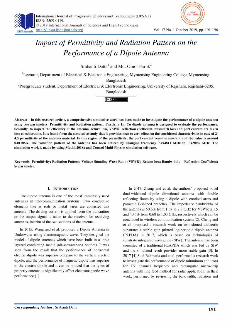
769 International Journal of Progressive Sciences and Technologies (IJPSAT) ISSN: 2509-0119. © 2019 International Journals of Sciences and High Technologies http://ijpsat.ijsht-journals.org Vol. 17 No. 1 October 2019, pp. 191-196 Corresponding Author: Srabanti Datta 191 Impact of Permittivity and Radiation Pattern on the Performance of a Dipole Antenna Srabanti Datta 1 and Md. Omor Faruk 2 1 Lecturer, Department of Electrical & Electronic Engineering, Mymensing Engineering College, Mymensing, Bangladesh 2 Postgraduate student, Department of Electrical & Electronic Engineering, University of Rajshahi, Rajshahi-6205, Bangladesh Abstract-- In this research article, a comprehensive simulative work has been made to investigate the performance of a dipole antenna using two parameters: Permittivity and Radiation pattern. Firstly, a 1m Cu dipole antenna is designed to evaluate the performance. Secondly, to inspect the efficiency of the antenna, return loss, VSWR, reflection coefficient, mismatch loss and port current are taken into consideration. It is found form the simulative study that it provides near to zero effect on the considered characteristics in case of 2- 4.5 permittivity of the antenna material. In this region of the permittivity, the port current remains constant and the value is around 0.01205A. The radiation pattern of the antenna has been noticed by changing frequency 7.494811 MHz to 134.9066 MHz. The simulation work is made by using Matlab2018a and Comsol Multi-Physics simulation software. Keywords- Permittivity; Radiation Pattern; Voltage Standing Wave Ratio (VSWR); Return loss; Bandwidth; —Reflection Coefficient; S- parameter. I. INTRODUCTION The dipole antenna is one of the most immensely used antennas in telecommunication systems. Two conductive elements like as rods or metal wires are consisted this antenna. The driving current is applied form the transmitter or the output signal is taken to the receiver for receiving antennas, interim of the two sections of the antenna. In 2015, Wang and et al. proposed a Dipole Antenna in Underwater using electromagnetic wave. They designed the model of dipole antennas which have been built in a three layered conducting media (air-seawater-sea bottom). It was seen from the result that the performance of horizontal electric dipole was superior compare to the vertical electric dipole, and the performance of magnetic dipole was superior to the electric dipole and it can be noticed that the types of property antenna is significantly affect electromagnetic wave performance [1]. In 2017, Zhang and et al. the authors’ proposed novel dual-wideband dipole directional antenna with double reflecting floors by using a dipole with crooked arms and parasitic Γ-shaped branches. The impedance bandwidths of the antenna is 50.6% from 1.67 to 2.8 GHz for VSWR ≤ 1.5 and 40.5% from 0.68 to 1.03 GHz, respectively which can be concluded in wireless communication system [2]. Cheng and et al. proposed a research work on two slotted dielectric substrates a stable gain printed log-periodic dipole antenna (PLPDA) in 2017, which is based on technologies of substrate integrated waveguide (SIW). The antenna has been consisted of a traditional PLAPDA which was fed by SIW and the simulated result provides more stable gain [3]. In 2017 [4] Suci Rahmatia and et al. performed a research work to investigate the performance of dipole (aluminum and iron) for TV channel frequency and rectangular micro-strip antenna with line feed method for radar application. In their work, performed by reviewing the bandwidth, radiation and
Transcript of Impact of Permittivity and Radiation Pattern on the ...
769 International Journal of Progressive Sciences and Technologies (IJPSAT)
ISSN: 2509-0119.
© 2019 International Journals of Sciences and High Technologies
http://ijpsat.ijsht-journals.org Vol. 17 No. 1 October 2019, pp. 191-196
Corresponding Author: Srabanti Datta 191
Impact of Permittivity and Radiation Pattern on the
Performance of a Dipole Antenna
Srabanti Datta1 and Md. Omor Faruk
2
1Lecturer, Department of Electrical & Electronic Engineering, Mymensing Engineering College, Mymensing,
Bangladesh 2Postgraduate student, Department of Electrical & Electronic Engineering, University of Rajshahi, Rajshahi-6205,
Bangladesh
Abstract-- In this research article, a comprehensive simulative work has been made to investigate the performance of a dipole antenna
using two parameters: Permittivity and Radiation pattern. Firstly, a 1m Cu dipole antenna is designed to evaluate the performance.
Secondly, to inspect the efficiency of the antenna, return loss, VSWR, reflection coefficient, mismatch loss and port current are taken
into consideration. It is found form the simulative study that it provides near to zero effect on the considered characteristics in case of 2-
4.5 permittivity of the antenna material. In this region of the permittivity, the port current remains constant and the value is around
0.01205A. The radiation pattern of the antenna has been noticed by changing frequency 7.494811 MHz to 134.9066 MHz. The
simulation work is made by using Matlab2018a and Comsol Multi-Physics simulation software.
Keywords- Permittivity; Radiation Pattern; Voltage Standing Wave Ratio (VSWR); Return loss; Bandwidth; —Reflection Coefficient;
S- parameter.
I. INTRODUCTION
The dipole antenna is one of the most immensely used
antennas in telecommunication systems. Two conductive
elements like as rods or metal wires are consisted this
antenna. The driving current is applied form the transmitter
or the output signal is taken to the receiver for receiving
antennas, interim of the two sections of the antenna.
In 2015, Wang and et al. proposed a Dipole Antenna in
Underwater using electromagnetic wave. They designed the
model of dipole antennas which have been built in a three
layered conducting media (air-seawater-sea bottom). It was
seen from the result that the performance of horizontal
electric dipole was superior compare to the vertical electric
dipole, and the performance of magnetic dipole was superior
to the electric dipole and it can be noticed that the types of
property antenna is significantly affect electromagnetic wave
performance [1].
In 2017, Zhang and et al. the authors’ proposed novel
dual-wideband dipole directional antenna with double
reflecting floors by using a dipole with crooked arms and
parasitic Γ-shaped branches. The impedance bandwidths of
the antenna is 50.6% from 1.67 to 2.8 GHz for VSWR ≤ 1.5
and 40.5% from 0.68 to 1.03 GHz, respectively which can be
concluded in wireless communication system [2]. Cheng and
et al. proposed a research work on two slotted dielectric
substrates a stable gain printed log-periodic dipole antenna
(PLPDA) in 2017, which is based on technologies of
substrate integrated waveguide (SIW). The antenna has been
consisted of a traditional PLAPDA which was fed by SIW
and the simulated result provides more stable gain [3]. In
2017 [4] Suci Rahmatia and et al. performed a research work
to investigate the performance of dipole (aluminum and iron)
for TV channel frequency and rectangular micro-strip
antenna with line feed method for radar application. In their
work, performed by reviewing the bandwidth, radiation and

Impact of Permittivity and Radiation Pattern on the Performance of a Dipole Antenna
Vol. 17 No. 1 October 2019 ISSN: 2509-011 192
return loss of both antenna in simulation. The simulation
results represent the comparison of performance between the
dipole antenna two materials and the rectangular micro-strip
patch antenna’s performance using the dimension of selected
parameters.
In this present study, a dipole antenna has been designed
and performance has been investigated. Such antenna can
achieve a higher attainable data transmission, with lower
return loss, VSWR as compared to the conventional antenna.
II. ANTENNA DESIGN AND ANALYSIS
The model of the dipole antenna consists of two cylinders
which represented by both of the dipole arms and arms are
1m long which aligned with the z-axis. For designing the
antenna surrounding, free space air is considered. A small
cylindrical gap is taken between the two arms, which works
as voltage source. A uniform voltage source consisting of
electromagnetic fields and surface current is applied across
the conductive faces of the antenna.
Figure 1: The (a) Geometry (b) Antenna model with PML,
(c) Antenna model with Mesh of the Cu dipole antenna.
At first a sphere of air has been added to create perfectly
matched layer (PML) which acts as an absorber of radiation.
The radius of the air sphere has been taken as 2.5m or it can
be expressed as 2.5 x arm length. Then from the global
material section, Cu has been selected as the antenna
material. Afterword, the mesh has been adjusted manually
such that there are five elements per free space wavelength.
The maximum mesh size is 0.2m wavelength in free space.
To evaluate the antenna radiator with the level of the 2nd-
order polynomial, the maximum element size has been set as
smaller than the radius of the antenna. In this model
maximum element size is 0.8m and the growth rate of
maximum element size is 1.5 [6].
TABLE-1: DESIGNING PARAMETERS OF THE ANTENNA:
Operating wavelength 4m
Antenna arm length and radius 1m and 0.05m
Gap between antenna arms 0.01m
Electrical conductivity 5.998e7 S/m
Relative permeability 1
Port impedance 119+30i ohm
III. SIMULATION PROCESS
In order to determine the performance and efficiency of
the antenna, having the values of Return loss, Reflection co-
efficient, VSWR and Mismatch loss are needed. 67.4533
MHz has been used as operating frequency as maximum
return loss (13.230192743 (dB) is occurred for this
frequency. Hereafter, the value of Permittivity has been
changed to investigate the effect on antenna performance.
For determining VSWR, Reflection coefficient and
Mismatch loss following equations are used.
RL � �20log�Γ ……………………………….. (1)
Where, RL= Return loss, Γ =Reflelctioncoefficient
VSWR ����
���…………………………..………… (2)
ML � �10 log�1 � Γ� ……………….……..….. (3)
Where ML= Miss Match loss
IV. RESULT AND DISCUSSION
In this part, Simulation results have been presented
showing the impact of permittivity on various parameter of
an antenna and 2D radiation pattern of a Cu dipole antenna
on performance evaluation of a dipole antenna. The antenna
performance has been shown by observing the impact
Permittivity on different parameters.
Form the graphical illustration which is depicted in Fig 3
to Fig 7, it is keenly noticeable that the simulation system
shows comparatively small changes with changing of
permittivity. An illustration of the relation between Return
loss (dB) and permittivity of the antenna material has been
presented in Fig 3. It is presumed from the figure that if the

Impact of Permittivity and Radiation Pattern on the Performance of a Dipole Antenna
Vol. 17 No. 1 October 2019 ISSN: 2509-011 193
antenna is operated within a specified bandwidth then with
the increase of permittivity, antenna return loss decreases
slightly. Fig 3 follows the equation: Y=0.0067*X+ 13.2,
where Y = Rerun loss (dB) and X = Permittivity.
Figure 2: Flow chart of the designing procedure of the
dipole antenna.
The changes in Reflection-coefficient, VSWR and
Mismatch loss with the change in permittivity have been
delineated in Fig 4, Fig 5 and Fig 6 respectively. It is
observed from the graphical representation that all of these
parameters are affected negligibly by the change of
permittivity. It is found that the value of reflection
coefficient is 0.218017001 for the value of permittivity 1 and
then reaches to 0.21877446 for permittivity 5. The reflection
coefficient increases with the raise in permittivity but the
increment rate is very low. Also same scenarios are seen for
VSWR and mismatch loss. For the value of permittivity 1,
VSWR and mismatch loss is 1.55760036 and 0.211494486
respectively and the values get to 1.560080153 and
0.213004445 respectively for permittivity 5. Fig 7 depicts the
changes of port current with respect to permittivity. It is seen
from the figure that port current is almost steady for the
permittivity 2 to 4.5 and the constant value is around
0.01205A. It can be considered that the performance of the
antenna will not be varied considerably for this permittivity
range and the antenna performance will be efficient.
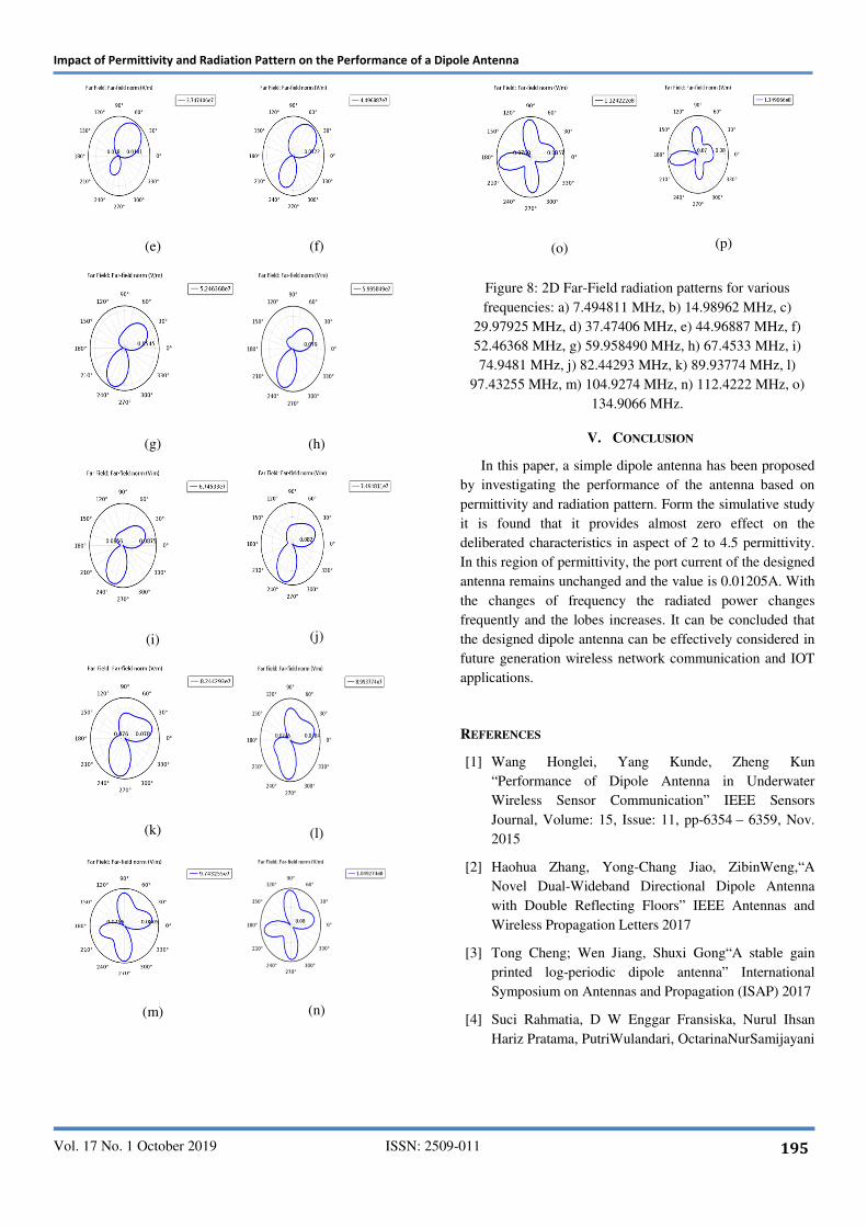
Hereafter, in this research work, the changes in radiation
pattern with various operating frequencies have also been
taken into consideration. Fig 8 represents the radiation
patterns of the antenna a various frequencies from 7.4948
MHz to 134.9066 MHz. For all he patterns, minimum
radiation occurs at θ = 00. In case of first two frequencies
i.e., 7.4948 MHz and 14.9896 MHz, maximum radiation
occurred at θ = 600 and for both cases there were only one
major lobes. However, all the patterns behaved differently
with degraded radiation characteristics as the frequency
increased. At higher frequencies, the radiated power was not
concentrated at θ = 600 but it rather spread to the neighbor
lobes.
Figure 3: Graphical representation of permittivity with
respect to Return-loss.

Impact of Permittivity and Radiation Pattern on the Performance of a Dipole Antenna
Vol. 17 No. 1 October 2019 ISSN: 2509-011 194
Figure 4: Graphical representation of Permittivity with
respect to Reflection coefficient.
Figure 5: Graphical representation of Permittivity with
respect to VSWR.
Figure 6: Graphical representation of Permittivity with
respect to Mismatch loss.
Figure 7: Graphical representation of permittivity with
respect to Port Current.
(a)
(b)
(c)
(d)
Impact of Permittivity and Radiation Pattern on the Performance of a Dipole Antenna
Vol. 17 No. 1 October 2019 ISSN: 2509-011 195
(e)
(f)
(g) (h)
(i)
(j)
(k)
(l)
(m)
(n)
(o)
(p)
Figure 8: 2D Far-Field radiation patterns for various
frequencies: a) 7.494811 MHz, b) 14.98962 MHz, c)
29.97925 MHz, d) 37.47406 MHz, e) 44.96887 MHz, f)
52.46368 MHz, g) 59.958490 MHz, h) 67.4533 MHz, i)
74.9481 MHz, j) 82.44293 MHz, k) 89.93774 MHz, l)
97.43255 MHz, m) 104.9274 MHz, n) 112.4222 MHz, o)
134.9066 MHz.
V. CONCLUSION
In this paper, a simple dipole antenna has been proposed
by investigating the performance of the antenna based on
permittivity and radiation pattern. Form the simulative study
it is found that it provides almost zero effect on the
deliberated characteristics in aspect of 2 to 4.5 permittivity.
In this region of permittivity, the port current of the designed
antenna remains unchanged and the value is 0.01205A. With
the changes of frequency the radiated power changes
frequently and the lobes increases. It can be concluded that
the designed dipole antenna can be effectively considered in
future generation wireless network communication and IOT
applications.
REFERENCES
[1] Wang Honglei, Yang Kunde, Zheng Kun
“Performance of Dipole Antenna in Underwater
Wireless Sensor Communication” IEEE Sensors
Journal, Volume: 15, Issue: 11, pp-6354 – 6359, Nov.
2015
[2] Haohua Zhang, Yong-Chang Jiao, ZibinWeng,“A
Novel Dual-Wideband Directional Dipole Antenna
with Double Reflecting Floors” IEEE Antennas and
Wireless Propagation Letters 2017
[3] Tong Cheng; Wen Jiang, Shuxi Gong“A stable gain
printed log-periodic dipole antenna” International
Symposium on Antennas and Propagation (ISAP) 2017
[4] Suci Rahmatia, D W Enggar Fransiska, Nurul Ihsan
Hariz Pratama, PutriWulandari, OctarinaNurSamijayani

Impact of Permittivity and Radiation Pattern on the Performance of a Dipole Antenna
Vol. 17 No. 1 October 2019 ISSN: 2509-011 196
“Designing dipole antenna for TV application and
rectangular microstrip antenna working at 3 GHz for
radar application” 2017 5th International Conference on
Cyber and IT Service Management (CITSM), 8-10
Aug. 2017
[5] ingtaoZeng, Kwai-Man Luk “A Simple Wideband
Magneto electric Dipole Antenna with a Defected
Ground Structure” IEEE Antennas and Wireless
Propagation Letters, Volume: 17, Issue: 8, Aug. 2018
[6] Dr. P. Siddaiah S Nagakishore Bhavanam, Vasujadevi
Midasala “Design of Dipole Antenna by Using
COMSOL Multiphysics Software” Proceedings of
International Conference on Innovations in Electronics
and Communication Engineering (ICIECE 2014), pp-
25-27.
[7] Undergraduate Research Opportunity Project
(UROP’02), Design of A Dipole Antenna Using
Computer Simulation, Student: Nguyen, Tran
ThanhBinh School of Electrical & Electronic
Engineering, Nayang Technological University.
[8] Srabanti Datta and Md. Omor Faruk “Design &
Performance Evaluation of a Dipole Antenna Using
Various Lengths of Antenna Material” International
Journal of Scientific & Engineering Research Volume
10, Issue 1, pp-1509-1514, January 2019.
[9] Lei Chang, Ling Lu Chen, Jian Qiang Zhang, Dan Li
“A Broadband Dipole Antenna with Parasitic Patch
Loading” IEEE Antennas and Wireless Propagation
Letters vol: 17, Issue: 9, pp- 1717 – 1721, Sept. 2018
[10] Oh-Seog Choi, Young-Chan Moon, Heon-JeongJeong,
“Broadband dipole antenna” United States Patent 2015
[11] S. A. Adekola, V. O. Adewuyi “On the electromagnetic
characteristics of dipole antennas at
MF/HF/VHF/UHF” 2017 IEEE 3rd International
Conference on Electro-Technology for National
Development (NIGERCON) 2017
[12] Nguyen, Tran Thanh Binh; A/P Hui Hon Tat; Design of
a dipole antenna using computer simulation.
[13] Haohua Zhang, Yong-Chang Jiao, Zibin Weng; A
Novel Dual-Wideband Directional Dipole Antenna
with Double Reflecting Floors, IEEE Antennas and
Wireless Propagation Letters 2017