Impact of Design on Product Cost Cost of Design...
24
1 1 Assembly and Joining 2 Manufacture Unit Manufacturing Processes Unit Manufacturing Processes Assembly and Joining Assembly and Joining Market Research Factory, Systems & Enterprise •Welding •Bolting •Bonding •Soldering •Machining •Injection molding •Rapid prototyping •Stamping •Chemical vapor deposition Conceptual Design Design for Manufacture 3 Impact of Design on Product Cost The majority of cost commitment is made early in the product design cycle. Cost in Percent Conception Validation Development Production Operation Time Source:British Aerospace 100 0 10 20 30 40 50 60 70 80 90 85% 95% 5% 20% Committed Spent 4 Cost of Design Changes CONCEPT DESIGN X 10X TOOLING TESTING 100X 1000X RELEASE 10,000X
Transcript of Impact of Design on Product Cost Cost of Design...

1
1
Assembly and Joining
2
Manufacture
Unit Manufacturing
Processes
Unit Manufacturing
ProcessesAssembly and
JoiningAssembly and
Joining
MarketResearch
Factory, Systems & Enterprise
•Welding•Bolting•Bonding•Soldering
•Machining•Injection molding•Rapid prototyping•Stamping•Chemical vapor deposition
ConceptualDesign
Design forManufacture
3
Impact of Design on Product Cost
The majority of cost commitment is made early in the product design cycle.
Cost inPercent
ConceptionValidation
DevelopmentProduction
Operation
TimeSource:British Aerospace
100
0
10
20
30
40
50
60
70
80
90
85%
95%
5%
20%
Committed
Spent
4
Cost of Design Changes
CONCEPT
DESIGN
X
10X
TOOLING
TESTING
100X
1000X
RELEASE
10,000X

2
5
“The best design is thesimplest one that works”
Albert Einstein
6
Assembly and Joining• Assembly as a mfg process
– Process components– Cost, Quality, Rate and Flexibility
• Specific joining processes– Mechanical– Adhesives– Solder and brazing– Cold welding– Fusion welding
7
Assembly statistics
8
Justifying the need/type of assembly
•For assembly– Can’t be made in
one piece– Functional
(bushings, bearings)– Manufacturability– Repair and
maintenance– Transport: Does it fit
in a plane?
•Against assembly– Defects that occur at
interfaces– Loss of stiffness– Time & effort– Labor costs– Size
3
9
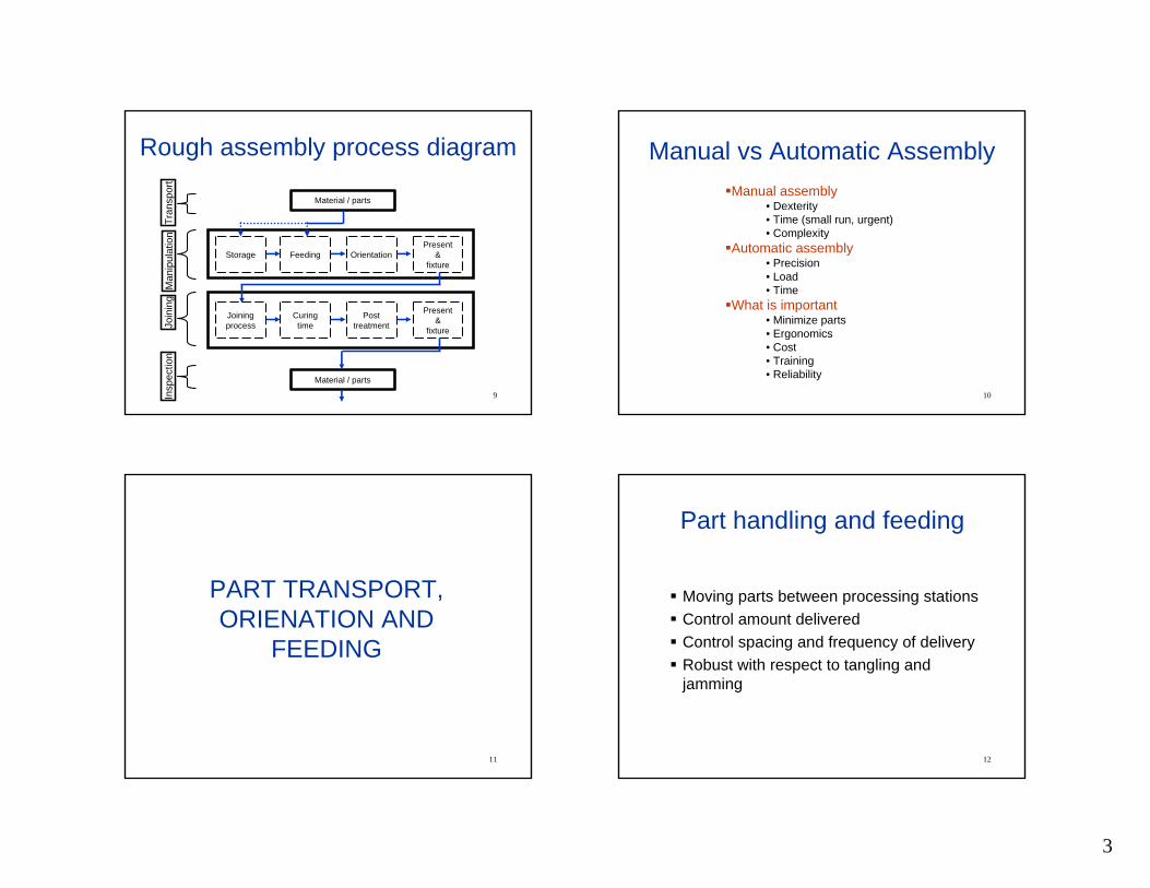
Rough assembly process diagram
Material / parts
Feeding OrientationStoragePresent
&fixture
Man
ipul
atio
nTr
ansp
ort
Join
ing
Curingtime
Posttreatment
Joiningprocess
Present&
fixture
Insp
ectio
n
Material / parts
10
Manual vs Automatic AssemblyManual assembly
• Dexterity• Time (small run, urgent)• Complexity
Automatic assembly• Precision• Load• Time
What is important• Minimize parts• Ergonomics• Cost• Training• Reliability
11
PART TRANSPORT, ORIENATION AND
FEEDING
12
Part handling and feeding
Moving parts between processing stationsControl amount deliveredControl spacing and frequency of deliveryRobust with respect to tangling and jamming

4
13
Part transport: Overhead
http://www.tegopi.pt/pt/novidades/images/25-10-2000.jpg http://accosystems.com/autoclient%20(2).jpg
14
Part transport: Conveyor
http://www.ssiconveyors.com/pics/ http://www.ssiconveyors.com/pics/
15
Part transport: Transfer line
16
AGV
Pallet load / unload
mechanism
WorkpiecePallet
Safeguards against collision

5
17
Part feeding and orientation
18
Part feeding and orientation
19
Part feeding and orientation
20
Part feeding and orientation

6
21
Guidelines to Good Design-for-Assembly
Minimize the number of partsDesign assembly process in a layered fashionConsider ease of part handlingUtilize optimum attachment methodsConsider ease of alignment and insertionAvoid design features that require adjustments
22
DFA - Example
0.10.20.30.40.50.60.70.80.91.0
024 8 4 2
Annual production volumes :robotic - 200,000automatic - 2,400,000
Ass
embl
y co
st ($
)
Number of parts
Minimize the number of parts
23
Minimize the number of parts
DFA - Example
24
Design assembly process in a layered fashion
DFA - Example

7
25
Consider ease of part handling
DFA - Example
26
Consider ease of part handling
DFA - Example
27
Utilize optimum attachment methods
DFA - Example
28
Utilize optimum attachment methods
10 20 30 40 50 100 2000
2
4
6
8 box-end wrench
open-end wrench
Socket ratchet wrenchNut driver
Clearance, mm
Run
dow
n tim
e / r
ev, s
Clearance
Clearance
Hex-nut driver
Socket ratchet wrench
Box-end wrench
Open-end wrench
DFA - Example

8
29
Utilize optimum attachment methodsDFA - Example
30
Utilize optimum attachment methodsDFA - Example
31
Consider ease of alignment and insertion
Design parts to maintain location
DFA - Example
32
Consider ease of alignment and insertion
Mating parts should be easy to align and insert
DFA - Example

9
33
Consider ease of alignment and insertionDFA - Example
34
Avoid design features that require adjustmentsDFA - Example
35
Avoid restricted vision
DFA - Example
36
Avoid obstructed accessDFA - Example

10
37
Joining
Assembly cost often account for more than 50%Joining processes
High scrap costFailure spot
38
Joining processes/types
39
Selection Criteria
GeometryMaterial typeValue of end productSize of product runAvailability of joining method
40
MECHANICAL JOINING
11
41
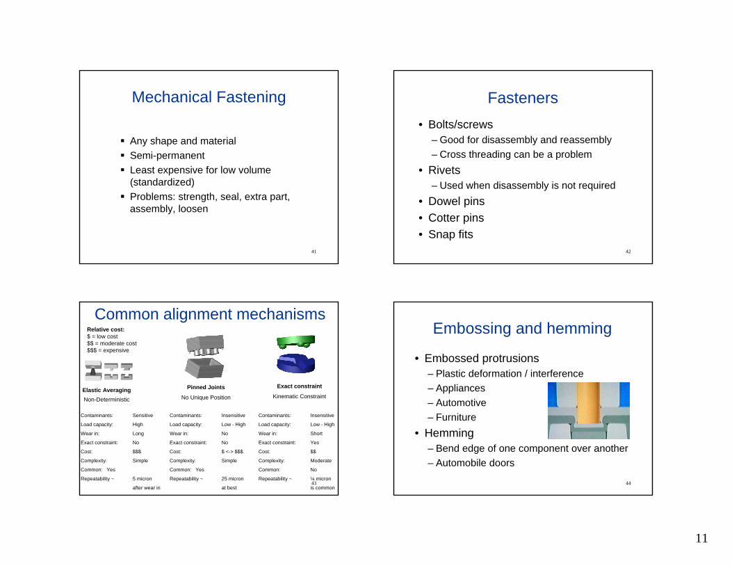
Mechanical Fastening
Any shape and materialSemi-permanentLeast expensive for low volume (standardized)Problems: strength, seal, extra part, assembly, loosen
42
Fasteners• Bolts/screws
– Good for disassembly and reassembly– Cross threading can be a problem
• Rivets– Used when disassembly is not required
• Dowel pins• Cotter pins• Snap fits
43
Elastic AveragingNon-Deterministic
Pinned Joints
No Unique Position
Exact constraint
Kinematic Constraint
Common alignment mechanisms
Contaminants: Sensitive
Load capacity: High
Wear in: Long
Exact constraint: No
Cost: $$$
Complexity: Simple
Common: Yes
Repeatability ~ 5 micron
after wear in
Contaminants: Insensitive
Load capacity: Low - High
Wear in: No
Exact constraint: No
Cost: $ <-> $$$
Complexity: Simple
Common: Yes
Repeatability ~ 25 micron
at best
Contaminants: Insensitive
Load capacity: Low - High
Wear in: Short
Exact constraint: Yes
Cost: $$
Complexity: Moderate
Common: No
Repeatability ~ ¼ micron
is common
Relative cost:$ = low cost$$ = moderate cost$$$ = expensive
44
Embossing and hemming
• Embossed protrusions– Plastic deformation / interference– Appliances– Automotive– Furniture
• Hemming– Bend edge of one component over another– Automobile doors

12
45
Press fits
( ) ( )( ) ⎥
⎦
⎤⎢⎣
⎡−⋅⋅−⋅−
⋅⋅=io
io
rrRrRRr
REp 222
2222
2δ
ro
R
ri
insertinsert xRpF ⋅⋅⋅⋅⋅= πµ 2
TRthermal ∆⋅⋅=αδ
δ = radial interference α = Coefficient of thermal expansionE = Young’s modulus ∆T = Temperature changep = interface pressure
Insertion force for press fit
0
500
1000
1500
2000
2500
3000
0.00 0.05 0.10 0.15 0.20 0.25
Press Depth, in
Pres
s Fo
rce,
lbf
46
ADHESIVEJOINING
47
Example – Adhesive Bonding
48
Adhesive joining
• Advantages– Different materials, Easily automated, Damp /seal
• Limitations– Time, Preparation/curing, Loading
• Important properties/characteristics of adhesives– Strength, Chemically inert, Compatibility

13
49
Adhesive BondingQuick, non-invasive, inexpensiveLow stressVariety of materialsSealLow part countTemperature-limitedLong set timeSurface preparationReliability/disassemblyBest for components with high surface to volume ratio
50
Stefan Equation
u
y
r
a
h/2h/2
F
⎥⎥⎦
⎤
⎢⎢⎣
⎡−= 22
4 114
3
if hhaFt µπ
51
What does Stephan equation mean?
⎟⎟⎠
⎞⎜⎜⎝
⎛⋅
⋅⋅⋅≈⋅ 2
4 14
3
finalfinal h
atF πµ
Viscosity: Start with low µ & finish with high µ
Gap: Small assembled gap
52
DFM with adhesives• What is important
– Matching type of loading to the design (shear/tension vs. peeling)
– Maximizing contact area
Poor
Good
Poor
Good
Poor
Good
14
53
BRAZING&
SOLDERING
54
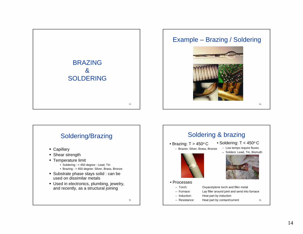
Example – Brazing / Soldering
55
Soldering/Brazing
CapillaryShear strengthTemperature limit
• Soldering : < 450 degree : Lead, Tin• Brazing : > 450 degree: Silver, Brass, Bronze
Substrate phase stays solid : can be used on dissimilar metalsUsed in electronics, plumbing, jewelry, and recently, as a structural joining
56
Soldering & brazing• Brazing: T > 450o C
– Brazes: Silver, Brass, Bronze
• Soldering: T < 450o C– Low temps require fluxes– Solders: Lead, Tin, Bismuth
• Processes– Torch: Oxyacetylene torch and filler metal– Furnace: Lay filler around joint and send into furnace– Induction: Heat part by induction– Resistance: Heat part by contact/current

15
57
Anatomy of solder/brazing process
•Purpose of fluxes– Remove oxides– Protect from oxidization– Improve surface wetting
•Process– A. Flux on top of oxidized metal – B. Boiling flux removes oxide– C. Base metal in contact with molten flux– D. Molten solder displaces molten flux – E. Solder adheres to base metal
– F. Solder solidifies58
DFA for Soldering and BrazingProvide large surface area contactFiller metal should have good wetting characteristics (capillary action)Joined surfaces should not be smooth
59
COLD WELDING (Interatomic)
PROCESSES
60
Ultrasonic and friction welding• Ultrasonic welding (shear @ 10 to 75kHz vibration)
– Contamination is redistributed, not displaced– Example: Wires/connectors in electronics components
• Friction welding– Material surfaces sheared against each other– Some metal extrudes out of weld zone, removes
contaminates
16
61
Diffusion bonding• Diffusion bonding is often divided into three stages
– Asperities + pressure = decreased interface porosity– Continued heating causes the porosities to shrink– Crystals grow across interface, some porosity may be trapped
• Time: Important variables/parameters:– Pressure = (500 to 5,000 psi) Temperature (2/3 Tmelt)– Surface finish Surface cleanliness
62
FUSIONWELDINGPHYSICS
63
Example – Spot Welding
64
• Process of fusing two materials to join them• Challenges in fusion welding
– Disrupting oxide layers and contamination
– Achieving high % surface area contact
Fusion welding

17
65
Welding
Heat sourceHeat intensity
• Control (overmelting/evaporation)• Heat affected zone (HAZ)• Efficiency• Depth/width ratio
66
Heat IntensityA measure of radiation intensity, W/cm2
Obviously the more intense the source, the faster the meltingVery difficult to prevent overmelting, therefore automation!
102 103 104 105 106 107
Air/FuelGas Flame
ElectroslagOxyacetylene
ThermitFriction
ArcWelding
Resistance Welding(Oxygen Cutting)
Electron Beam,Laser Beam
67
Heat intensity and interaction time• Heat intensity (in W/cm2)
– HI = Power per unit area directed into the welding zone– HI ~103 melting in < 25 seconds– HI ~106 vaporizes metal in µseconds
• Propagation of heat in solids: x ~ (α·t)0.5
– x = distance thermal disturbance travels into thick slab – t = elapsed time
ρ k cp α Tmeltg/cm3 W/m/K J/g/oC cm^2/s oC oF
Aluminum 2.7 200 0.890 0.832 660 1220
Copper 8.9 400 0.385 1.167 1085 1985
1020 steel 7.9 50 0.448 0.141 1500 2732
Delrin 1.4 0.36 1.464 0.002 175 34768
Weld pool from 2D simplification
tJs
ck
hTTcJ
a
p
fs
initialmeltpa
α
ρα
2
)(
=
=
−=
: as moves front melt The
. by given is ydiffusivit thermal The
. number, Jacob The
s

18
69
Welding Rate
The rate at which the welding device must be moved is governed by:
The Heat Intensity - the greater the intensity, the faster the motion must be to keep the weld pool size, smax, constantThe product, α Ja, The greater it is, the faster the melt front moves
70
Welding Rate (cont.)In fact, the time at a spot, tmax is given by s2
max/ 2α Ja. Anymore, and you over-melt!
If the weld pool size is d in length, then you must feed at a rate that exceeds d/tmax. Similarly a lower limit.
Weld pool size d
Vmin = d / tmax
71
• Definitions of Jacob # and thermal diffusivity:
• Solidification front moves in “s” direction as:
• To maintain constant weld pool depth at s
Melting front and welding velocity
pck⋅
=ρ
αfs
initialmeltp h
TTcJ −⋅=
max2 tJs ⋅⋅⋅= α
maxtdVweld >
72
Welding Rate (cont.)
For a planar heat source on steel, tm= (5000/H.I.)2
: where H.I. Is the heat intensity in W/cm2. The number 5000 includes the material constant related terms.
Clearly the greater the H.I. The faster the metal melts.
19
73
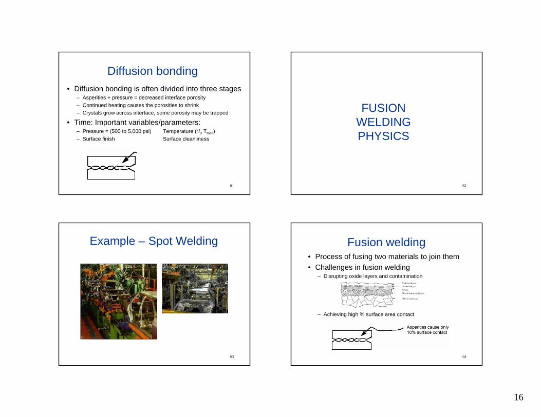
Weld Pool – Heat Source Interaction Time
10-3
10-2
10-1
100
101
102
103
104
105
106
107
108
103 104 105 106 107 108
103
102
101
100
10-1
10-2
10-3
10-4
10-5
10-6
10-7
10-8
Heat Intensity (Watts/cm2)
Inte
ract
ion
Rat
e (S
econ
ds-1
)
Inte
ract
ion
Tim
e (S
econ
ds)
Copper,Aluminum
Steels,Nickels
Uranium,Ceramics
Hig
her α
, Ja
Main factor : Thermal diffusivity 74
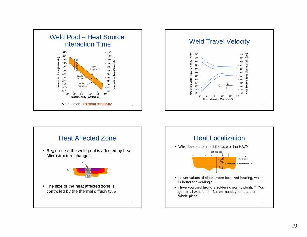
Weld Travel Velocity
102
101
100
10-1
10-2
10-3
10-4
10-5
10-6
10-7
10-8
10-9
103 104 105 106 107 108
109
108
107
106
105
104
103
102
101
100
10-1
10-2
Heat Intensity (Watts/cm2)
Hea
t Sou
rce
Spot
Dia
met
er, d
n(c
m)
Max
imum
Wel
d Tr
avel
Vel
ocity
(cm
/s)
)(maxmI
IH
ttdV •=
75
Heat Affected Zone
Region near the weld pool is affected by heat. Microstructure changes.
The size of the heat affected zone is controlled by the thermal diffusivity, α.
s
76
Heat LocalizationWhy does alpha affect the size of the HAZ?
Lower values of alpha, more localized heating, which is better for welding?Have you tried taking a soldering iron to plastic? You get small weld pool. But on metal, you heat the whole piece!
Heat applied
Temperature
Increasing α or decreasing α?

20
77
FUSION WELDING
PROCESSES
78
Oxyfuel gas welding• Air/fuel welding
– Low-cost, portable and flexible– Oxidizing and reducing flames
79
General arc welding• Voltage difference between electrode & work piece
– Voltage ~ 100 - 500 V– Current ~ 50 – 300 A
• Electrode may be consumed
80
Fillers and shielding in arc welding
• Filler metals– Adds metal to weld zone– Flux on/in filler cleans/prevents oxidization– Slag protects molten puddle from oxidation
• Shielding– Pellets or grains– Gaseous

21
81
General resistance welding• High current through weld area (3k – 40k
Amps)– Important: contact pressure & weld current & weld time– Simple, reliable fusion processes– Welds often not easy to inspect ( i.e. spot welds )– Energy in: i2 R t– Energy req’d: ?– Melting requires ~ 1400 J / g for steel
82
Electron beam and laser welding
• Electron beam– Uses electrons to transfer energy
• Laser welding– Uses photons to transfer energy
• Pros and cons– Advantages: Small HAZ– Disadvantages: $$$!, deep welds require careful fixturing
83
FUSIONWELDINGDEFECTS
84
Typical defects
Source: American Welding Society

22
85
Porosity and inclusions
• Common causes– Trapped gases– Contaminants– Flux particles
• Prevention– Pre-heat– Pre-cleaning– Improved shielding
86
Cracks in welds• Usually result from one or combo of:
– Temperature gradients and inability of metal to contract during cooling
• Prevention– Preheat components or design to minimize stress
from thermal shrinking
87
Residual stresses• Residual stresses cause problems
– Distortion on welding– Reduce fatigue life
• Prevention– Preheating– Stress relieving in furnace (post heating)
A B 88
Heat affected zone (HAZ)• Material is not melted, but is heated• Properties in HAZ differ and depend on:
– Temperature– Time– Original properties– HI

23
89
FUSIONWELDING
DFM
90
DFM for Welding
One-half the weld metal same strength Twice the
weld metal -same strength
Previous Design 21 Pieces Improved
3 Pieces
Design simplicity can save much welding and assembly time
91
DFM for Welding (conti.)Electrode must be held close to 45° when making these fillers
Easy to draw, but the 2nd weld will be hard to make
Very difficult
Easy
Easy to specify “weld all around” but …..
Try to avoid placing pipe joints near wall so that one or two sides are
inaccesible. These welds must be made with bent electrodes and mirror
Too close to side to allow proper electrode positioning. May be OK for average work but bad for leakproof welding
Pipe
Wall
92
• Cracks open in tension
• Most welds are hard, not easily machined
• Part preparation
DFM for welding

24
93
Cost - JoiningMetal arc welding
Low tooling costs, moderate equipment costsHigh direct labor costsEconomical for low production runs
Resistance weldingLow tooling costs, high equipment costsLow direct labor costsFull automation can be easily formed
Soldering / BrazingLow tooling costs, various equipment costs depending on the automation levelLow to moderate direct labor costs
Adhesive bondingLow tooling costs, moderate equipment costsLow direct labor costs
94
Quality - JoiningMetal arc welding
Relatively moderate HAZ existsGood surface finish
Resistance weldingClean, high quality welding with low distortionSmall HAZHigh strength welds are produced by flash welding
Soldering / BrazingVirtually stress and distortion free jointsExcellent surface finish
Adhesive bondingExcellent quality joints with virtually no distortionJoint strength may deteriorate with time and sever environment conditions
95
Rate - JoiningMetal arc welding
Economical for low production runs – manual weldingWell suited to traversing automated and robotic systems
Resistance weldingHigh production rate is possible due to short weld timesEasy full automation
Soldering / BrazingHigh production rates are possible for dip soldering ex>Printed Circuit Boards
Adhesive bondingLow production runs
96
Flexibility - joining
Metal arc weldingGenerally high flexibility but depends on the automation level
Resistance weldingLow flexibility due to high automation level
Soldering / BrazingVarious level of automation is possible
Adhesive bondingVery flexible processCan aid weight minimization in critical applications