Impact Blow Valve - Amazon Web Services
3
Pressure Labor time 0 Impact Blow Valve IBV-X5 Continuous blow IBV-X5: Air consumption Continuous blow air consumption 3 times or more ∗1 (Compared with the existing model) 93 % reduction ∗2 High peak pressure Air consumption Increased impact force due to higher peak pressure Drastic reduction in air consumption and labour time ∗1 According to blow conditions When the piping volume is 100 cc (Piping I.D. Ø 13, 800 mm) ∗2 Pressure: 0.5 MPa (Based on SMC’s specific testing conditions) Compact design allows for installation in narrow spaces Press plate IN port: Rc3/8 OUT port: Rc1/4 50 mm 46 mm 36 mm Solenoid Type/IBV-X5/X7 For the separation of workpieces stuck together with oil, etc. Use of piping instead of tanks (Tankless construction) ¡Miniaturization of valves ¡Instantaneous discharge and high peak pressure Sold Separately Long nozzle Nozzle length: 50/100/150/300 mm Long nozzle with a silencer 80 dB(A) ∗1 or less ∗1 Based on SMC’s measurement conditions · Supply pressure: 0.5 MPa · Inlet side piping conditions: 100 cc I.D. Length [mm] Peak pressure (Compared with the existing model) Ø 8 2000 2 times Ø 10 1300 2.5 times Ø 13 800 3 times ∗ Based on SMC’s measurement conditions ∗ Oscillation may occur if only a minimal amount of air is supplied. Use inlet piping with an inside diameter of Ø 8 or more, and take measures to prevent the pressure from dropping as much as possible. The peak pressure can be adjusted by the inlet piping volume. a silencer ons 5 MPa 1 (IN) 2 (OUT) INFORMATION 20-EU746-UK IBV -X5/X7
Transcript of Impact Blow Valve - Amazon Web Services

Pre
ssure
Labor time
0
Impact Blow Valve
IBV�-X5Continuous blow
IBV�-X5: Air consumption
Continuous blow air consumption
3 times or more∗1
(Compared with the existing model)
93 %reduction∗2
High peak pressure Air consumption
Increased impact force due to higher peak pressureDrastic reduction in air consumption and labour time
∗1 According to blow conditions
When the piping volume is 100 cc (Piping I.D. Ø 13, 800 mm)
∗2 Pressure: 0.5 MPa (Based on SMC’s specific testing conditions)
Compact design allows for installation in narrow spaces
Press plate
IN port:
Rc3/8
OUT port:
Rc1/4
50 mm
46 mm36 mm
Solenoid Type/IBV�-X5/X7
� For the separation of workpieces stuck together with oil, etc.
� Use of piping instead of tanks(Tankless construction)
¡Miniaturization of valves
¡Instantaneous discharge and high peak pressure
Sold Separately
Long nozzle
Nozzle length:
50/100/150/300 mm
Long nozzle with a silencer
80 dB(A)∗1 or less∗1 Based on SMC’s
measurement conditions· Supply pressure: 0.5 MPa· Inlet side piping conditions: 100 cc
I.D. Length [mm]Peak pressure
(Compared with the existing model)
Ø 8 2000 2 times
Ø 10 1300 2.5 times
Ø 13 800 3 times
∗ Based on SMC’s measurement conditions∗ Oscillation may occur if only a minimal amount of air is supplied. Use
inlet piping with an inside diameter of Ø 8 or more, and take measures to prevent the pressure from dropping as much as possible.
The peak pressure can be adjusted by the inlet piping volume.
a silencer
ons5 MPa
1(IN)
2(OUT)
INFORMATION
20-EU746-UK
IBV �-X5/X7
33.9
(10) (35)
38.3
52.2
39
36
22.1
15
6.5
46
42.5
36
21.4
(50)
23.5
11.8
28.5 21.5
30
18
36 14
19.1
38.3
54.5
59.5
362
8
22.1
15
6.5
36
42.5
46
28
2 x Ø 4.6
18
11.8
2 x Ø 4.6
V111-5WA1
28
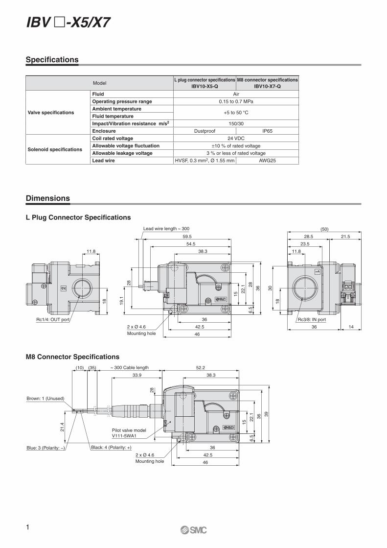
L Plug Connector Specifi cations
M8 Connector Specifi cations
Specifi cations
Dimensions
ModelL plug connector specifi cations
IBV10-X5-Q
M8 connector specifi cations
IBV10-X7-Q
Valve specifications
Fluid Air
Operating pressure range 0.15 to 0.7 MPa
Ambient temperature+5 to 50 °C
Fluid temperature
Impact/Vibration resistance m/s2 150/30
Enclosure Dustproof IP65
Solenoid specifications
Coil rated voltage 24 VDC
Allowable voltage fluctuation ±10 % of rated voltage
Allowable leakage voltage 3 % or less of rated voltage
Lead wire HVSF, 0.3 mm2, Ø 1.55 mm AWG25
1
IBV �-X5/X7
Rc1/4: OUT port
Mounting hole
Mounting hole
Lead wire length ≈ 300
Rc3/8: IN port
Brown: 1 (Unused)
Blue: 3 (Polarity: −) Black: 4 (Polarity: +)
Pilot valve model
≈ 300 Cable length

Specifications are subject to change without prior notice and any obligation on the part of the manufacturer.
SMC CORPORATION Akihabara UDX 15F, 4-14-1, Sotokanda, Chiyoda-ku, Tokyo 101-0021, JAPAN Phone: 03-5207-8249 FAX: 03-5298-5362
SMC Corporation (Europe)
1st printing ZP printing ZP 00 Printed in Spain
Lithuania +370 5 2308118 www.smclt.lt [email protected] +31 (0)205318888 www.smc.nl [email protected] +47 67129020 www.smc-norge.no [email protected] +48 222119600 www.smc.pl [email protected] +351 214724500 www.smc.eu [email protected] +40 213205111 www.smcromania.ro [email protected] +7 8123036600 www.smc.eu [email protected] +421 (0)413213212 www.smc.sk [email protected] +386 (0)73885412 www.smc.si [email protected] +34 945184100 www.smc.eu [email protected] +46 (0)86031200 www.smc.nu [email protected] +41 (0)523963131 www.smc.ch [email protected] +90 212 489 0 440 www.smcpnomatik.com.tr [email protected] UK +44 (0)845 121 5122 www.smc.uk [email protected]
Austria +43 (0)2262622800 www.smc.at [email protected] +32 (0)33551464 www.smc.be [email protected] +359 (0)2807670 www.smc.bg [email protected] Croatia +385 (0)13707288 www.smc.hr [email protected] Republic +420 541424611 www.smc.cz [email protected] Denmark +45 70252900 www.smcdk.com [email protected] Estonia +372 6510370 www.smcpneumatics.ee [email protected] +358 207513513 www.smc.fi [email protected] +33 (0)164761000 www.smc-france.fr [email protected] +49 (0)61034020 www.smc.de [email protected] +30 210 2717265 www.smchellas.gr [email protected] +36 23513000 www.smc.hu [email protected] +353 (0)14039000 www.smcautomation.ie [email protected] +39 03990691 www.smcitalia.it [email protected] +371 67817700 www.smc.lv [email protected]
Selection Precautions
1. This product is based on the concept that the piping
volume connected to the inlet side can be used in
place of a tank, making a built-in tank unnecessary.
It is recommended that the inside diameter of the
inlet piping be as thick as possible.
Example) Inlet volume: 100 cc (piping volume equivalent to
IBG series)
· Piping I.D.: Ø 8 ···················· Length: 2000 mm
· Piping I.D.: Ø 10 ·················· Length: 1300 mm
· Piping I.D.: Ø 13 ·················· Length: 800 mm
∗ The blow pressure discharged can be adjusted by adjusting the inlet
side piping conditions.
∗ When not enough air is being supplied, the main valve will oscillate,
which may result in a reduced product life. Therefore, use inlet
piping with an inside diameter of Ø 8 or more, and take measures to
prevent the pressure from dropping as much as possible.
2. For the nozzle to be mounted on the outlet side, a
dedicated nozzle is recommended. If operating noise
is a concern, a silencing nozzle is also available.
Nozzle type Part number
Dedicated nozzle IBG1-12-10-�Silencing nozzle IBG1-12S
Set including the dedicated nozzle and
silencing nozzleIBG1-12-10-�S
∗ �: Nozzle length (50, 100, 150, 300)
3. The impact resistance and vibration resistance of
this product are 150 [m/s2] and 30 [m/s2], respec-
tively. Be sure to prevent impact or vibration exceed-
ing the allowable values from being applied to the
product.
Use Precautions
The air blow pressure is strong. Pay attention to the
following when using the product.
1. Do not use this product with the product directed at
the human body as it may cause injury.
2. Before use, make sure that the blow pressure, or
blow, will not cause surrounding objects to scatter
and injure others or damage workpieces, equipment,
etc., in the vicinity.
3. Air pressure may cause the nozzle to fly off during
operation if it is not properly tightened. To prevent
this, be sure to check the nozzle for loosening by
pulling on it with your hands before use.
4. If air is supplied from the air blow outlet by mistake,
it may result in product failure.
Impact Blow Valve IBV �-X5/X7