Impact behaviour of geo-cells used in rock fall protection ... · Impact behaviour of geo-cells...
10
Impact behaviour of geo-cells used in rock fall protection dykes S. Lambert 1 , D. Bertrand 1 , F. Nicot 1 & P. Gotteland 2 1 Cemagref, Unité ETNA, Grenoble, France 2 L3SR, 3S-R, UMR 5521 CNRS-UJF-INP, Grenoble, France Abstract The impact behaviour of composite geo-cells used as components of rock fall protection structures is studied experimentally. The response of single cells subjected to impact by a boulder vertically dropped with energies of 13.5kJ is analysed. The influence of the cell filling material and cell boundary conditions is discussed. The damping potential of an impacted cell appears to depend on these two conditions. Experimental results are then compared with numerical ones obtained using the discrete element method - DEM. Keywords: rock fall, protection, dyke, impact, geo-cell, gabion, geo-materials, dissipation, experiments, numerical. 1 Introduction Geo-cells can be defined as composite structures associating a manufactured envelope together with a granular filling material. Different types of geo-cells are employed in civil engineering structures for reinforcement purposes, with applications in embankments or reinforced walls. The envelope is generally made up of a geotextile, or related product, or wire netting. The filling material can be soil, crushed rock or any granular material. The sectional shape of the cell can either be a honeycomb, a parallelepiped or a circle. The geo-cells are generally interconnected. Such geo-cells can be used to build rock fall protection dykes, or dams. In mountainous regions, rock falls are very frequent events resulting in road blockages, infrastructure degradation and injury to humans. Among the different possible protection structures, dykes are the only one able to intercept blocks of translational kinetic energies over 5MJ. Classically these dykes are soil- © 2008 WIT Press WIT Transactions on the Built Environment, Vol 98, www.witpress.com, ISSN 1743-3509 (on-line) Structures Under Shock and Impact X 197 doi:10.2495/SU080201
Transcript of Impact behaviour of geo-cells used in rock fall protection ... · Impact behaviour of geo-cells...

Impact behaviour of geo-cells used in rock fall protection dykes
S. Lambert1, D. Bertrand1, F. Nicot1 & P. Gotteland2 1Cemagref, Unité ETNA, Grenoble, France 2L3SR, 3S-R, UMR 5521 CNRS-UJF-INP, Grenoble, France
Abstract
The impact behaviour of composite geo-cells used as components of rock fall protection structures is studied experimentally. The response of single cells subjected to impact by a boulder vertically dropped with energies of 13.5kJ is analysed. The influence of the cell filling material and cell boundary conditions is discussed. The damping potential of an impacted cell appears to depend on these two conditions. Experimental results are then compared with numerical ones obtained using the discrete element method - DEM. Keywords: rock fall, protection, dyke, impact, geo-cell, gabion, geo-materials, dissipation, experiments, numerical.
1 Introduction
Geo-cells can be defined as composite structures associating a manufactured envelope together with a granular filling material. Different types of geo-cells are employed in civil engineering structures for reinforcement purposes, with applications in embankments or reinforced walls. The envelope is generally made up of a geotextile, or related product, or wire netting. The filling material can be soil, crushed rock or any granular material. The sectional shape of the cell can either be a honeycomb, a parallelepiped or a circle. The geo-cells are generally interconnected. Such geo-cells can be used to build rock fall protection dykes, or dams. In mountainous regions, rock falls are very frequent events resulting in road blockages, infrastructure degradation and injury to humans. Among the different possible protection structures, dykes are the only one able to intercept blocks of translational kinetic energies over 5MJ. Classically these dykes are soil-
© 2008 WIT PressWIT Transactions on the Built Environment, Vol 98, www.witpress.com, ISSN 1743-3509 (on-line)
Structures Under Shock and Impact X 197
doi:10.2495/SU080201

reinforced structures, i.e. soil reinforced with horizontal inclusions such as geotextiles. They are massive with height varying from 3 up to 20m. and length of more than a few hundred meters. Building these dykes using geo-cells is a challenging way to optimize their conception, fully taking into account the dynamic response of the structure. In fact, resorting to geo-cells allows building sandwich protection structures (fig. 1). Depending on their location in the structure, the geo-cells are filled with different materials. The optimisation targeted with this kind of structure bears on the significant reduction of the efforts transmitted to the downstream part of the structure, e.g. the embankment in this illustration. This can be obtained favouring the deformation of front cells as well as core cells. In case of a higher energy impact, degradations may occur on the front of the structure. In addition, restoration is easily performed by replacing the damaged cells with new ones. In order to develop this new and promising type of rock fall protection structure studies were engaged, coupling experiments together with numerical developments and following a multi-scale approach, from the constitutive material to the structure scale. The cell response was first investigated under static loading. Then the impact response of cells was investigated considering different parameters: the boulder kinetic energy, the boundary conditions and the filling materials, [1]. The aim of this paper is to investigate the behaviour of geo-cells when submitted to impact by a boulder. The conditions for a higher reduction of the transmitted forces are discussed and experimental results are compared to numerical ones.
Figure 1: Principle of a cellular rock fall protection dyke.
2 Materials and method
2.1 Cell filing material and envelope
The filling materials were coarse granular materials or fine materials. The former were crushed carry limestone, 60 to 180mm in size, hereafter referred to as ‘gravel’. The latter consisted of sand or shredded tyres 30mm in average size (fig. 2). This material was considered both for waste valorisation purposes and
© 2008 WIT PressWIT Transactions on the Built Environment, Vol 98, www.witpress.com, ISSN 1743-3509 (on-line)
198 Structures Under Shock and Impact X
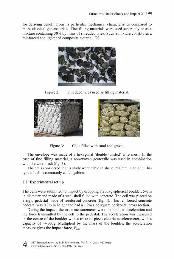
for deriving benefit from its particular mechanical characteristics compared to more classical geo-materials. Fine filling materials were used separately or as a mixture containing 30% by mass of shredded tyres. Such a mixture constitutes a reinforced and lightened composite material, [2].
Figure 2: Shredded tyres used as filling material.
Figure 3: Cells filled with sand and gravel.
The envelope was made of a hexagonal ‘double twisted’ wire mesh. In the case of fine filling material, a non-woven geotextile was used in combination with the wire mesh (fig. 3). The cells considered in this study were cubic in shape, 500mm in height. This type of cell is commonly called gabion.
2.2 Experimental set up
The cells were submitted to impact by dropping a 250kg spherical boulder, 54cm in diameter and made of a steel shell filled with concrete. The cell was placed on a rigid pedestal made of reinforced concrete (fig. 4). This reinforced concrete pedestal was 0.7m in height and had a 1.2m side square horizontal cross section. During the impact, the main measurements were the boulder acceleration and the force transmitted by the cell to the pedestal. The acceleration was measured in the centre of the boulder with a tri-axial piezo-electric accelerometer, with a capacity of +/-500g. Multiplied by the mass of the boulder, the acceleration measure gives the impact force, Fimp.
© 2008 WIT PressWIT Transactions on the Built Environment, Vol 98, www.witpress.com, ISSN 1743-3509 (on-line)
Structures Under Shock and Impact X 199

Figure 4: Principle of the experimental set up.
Figure 5: Gravel cells after impact in different boundary conditions: (a) FD, (b) RC and (c) MC (see text for definitions).
Due to the coarse nature of filling material it was not possible to measure the transmitted force just beneath the cell: this measure was made by three force transducers supporting the rigid pedestal (capacity of 500kN each) resting on a concrete slab. In order to simulate the possible boundary conditions at the structure scale three different cell boundary conditions were considered. The four lateral faces of the impacted cell were (i) free to deform – FD (ii) confined by the same material as their filling material – MC or (iii) rigidly confined – RC (fig. 5). Rigid confinement was obtained using three rigid steel square frames. Despite its simplicity, it appeared to satisfactorily confine the cell. In the case of MC conditions, the whole surface of the pedestal was covered with the confining material. It was laterally contained by a wood and steel case. The MC conditions offer the most realistic boundary conditions compared to RC and FD conditions. These latter are used to calibrate the numerical model.
3 Results
Results presented here concern 13.5 kJ impacts obtained dropping the boulder from a 5.5 m height. During the free fall and impact, the rotation of the boulder remains little. The impact point is well centred on the cell. The boulder rises again or rebounds after impacts on cells filled with sand and tyre-sand mixture, whatever the boundary
Boulder + accelerometer
Cell
Reinforced concrete pedestal
3 Load transducers Concrete slab
© 2008 WIT PressWIT Transactions on the Built Environment, Vol 98, www.witpress.com, ISSN 1743-3509 (on-line)
200 Structures Under Shock and Impact X

conditions, and also with cells filled with gravel and rigidly confined. In the case of free to deform cells, the cell deformation is higher with gravel. Impacts on this latter type of filling material lead to particle crushing. Table 1 gives the main results of impact tests in the various conditions. The test is identified referring to the filing material (Gra, San or Mix respectively for gravel, sand and mixture) and to the cell boundary conditions (FD, MC, RC respectively for free to deform, material confinement and rigid confinement). Tests labelled with a star were performed twice and results are mean values.
Table 1: Main impact test results.
Test reference
Max(Fimp) (kN)
Max(Ftrans) (kN)
Duration (ms)
Restitution (-)
Gra_FD* 144 77 105 (1)
Gra_MC* 105 201 38 (1)
Gra_RC* 242 377 26 0.12 San_FD 90 128 70 0.13 San_MC* 130 223 32 (1)
San_RC 346 601 22 0.18 Mix_FD* 120 150 60 0.13 Mix_MC 140 269 60 0.25
(1) low and not verifiable value (<0.1). The impact and transmitted forces given are the maximum values. This table also gives the impact duration and the restitution coefficient defined as the ratio between the velocity of the boulder just at the end of the impact and the velocity just before contact with the cell. Figure 6 shows the impact force and transmitted force measured during impacts on cells filled with sand and on cells filled with gravel, in the different boundary conditions. As the curves obtained for tyre-sand mixture cells are similar in shape to curves obtained with sand they are not presented here. From these results it is possible to extract the main trends concerning the influence of the two parameters considered: the boundary conditions and the filling material. For sake of simplicity, an impact test performed on a laterally free to deform cell filled with gravel, for instance, will be hereafter referred to as a FD gravel test.
4 Discussion
4.1 Influence of the boundary conditions
The results make stand out that restraining the lateral deformation of the cell greatly modifies the cell response. First, the shape of impact and transmitted force curves are significantly changed by the boundary conditions. The impact duration is reduced by a factor of three to four from FD conditions to RC
© 2008 WIT PressWIT Transactions on the Built Environment, Vol 98, www.witpress.com, ISSN 1743-3509 (on-line)
Structures Under Shock and Impact X 201
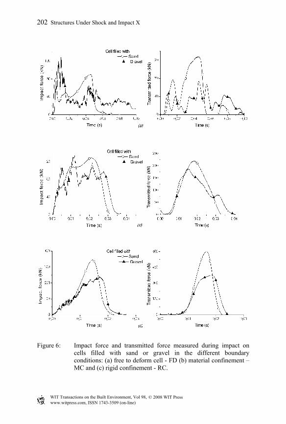
Figure 6: Impact force and transmitted force measured during impact on cells filled with sand or gravel in the different boundary conditions: (a) free to deform cell - FD (b) material confinement – MC and (c) rigid confinement - RC.
© 2008 WIT PressWIT Transactions on the Built Environment, Vol 98, www.witpress.com, ISSN 1743-3509 (on-line)
202 Structures Under Shock and Impact X

conditions. The maximum values of both the impact force and the transmitted force are increased. The increase of the maximum impact force is higher in the case of sand cells, with a factor of 3.8 vs. 1.7 for gravel cells. The increase of the maximum transmitted force is similar for both filling materials (factor of 4.8). The restitution coefficient is also increased.
4.2 Influence of the filling material
The shape of impact force curves measured for FD cells strongly depends on the filling material. The impact force measured on a gravel cell exhibits rapid variations over the whole duration of the impact and the maximum is reached at the beginning of the impact (10ms). In comparison, the impact force on a sand cell is rather smooth and the maximum value is reached about 40ms after the beginning of the impact. The transmitted force is also affected by the filling material, the sand cell exhibiting the highest value. For the other boundary conditions, the influence of the filling material is less important. Impact force curves for gravel cell always exhibit rapid variations compared to smooth curves obtained for sand cells. Results presented in table 1 indicate that the behaviour of a tyre-sand mixture cell is slightly different from the behaviour of a sand cell. Maximum forces values are higher in the first case. Whatever the boundary conditions it appears that the maximum value of the transmitted force is higher for cells filled with sand and tyre-sand mixture, compared to gravel.
4.3 Some phenomenological aspects
The response of a laterally free to deform cell reveals its composite nature. The cell is composed of two elements: the filling material and the envelope. The cell response depends on the characteristics of both. In the case of a gravel cell, the coarse nature of the filling material explains the rapid impact force variations. In such a media, the forces are supported by a few gravel columns. There exist ‘force chains’, [3]. Any movement or crushing of gravel in these columns leads to a sudden change in the impact force. In the case of a sand cell, the peak at the end of the impact is due to the confining effect by the envelope, [4]. When deformed, the envelope applies a confining stress on the filling material, increasing the impact force. This confinement effect is delayed due to (i) the initial cubic shape of the cell and (ii) to the hexagonal shape of the metallic mesh. The response of a free to deform cell, in term of impact force, thus clearly depends on both the filling material and the envelope. For FD and MC impact tests the maximum value of the impact force is almost the same for both material but the transmitted force is lower for gravel cells. This seems to be due to the crushing of the gravel, dissipating energy. Because of this phenomenon, the transmitted force is limited by the crushing resistance of gravel. In contrast, a fine filling material tends to compact during the impact: both the impact force and transmitted force are increased. This clearly brings out from RC boundary conditions impacts.
© 2008 WIT PressWIT Transactions on the Built Environment, Vol 98, www.witpress.com, ISSN 1743-3509 (on-line)
Structures Under Shock and Impact X 203
Thus, the impact force appears to be very interesting to understand the behaviour of the impacted structure. Nevertheless, this data is of limited interest considering the goal of this study compared to the transmitted force.
4.4 Cells efficiency in reducing the transmitted force
The efficiency of a cell to reduce the transmitted efforts is based on the transmitted force. But considering the transmitted force may not be fully sufficient to evaluate the efficiency of a cell at the structure scale. Indeed, this data doesn’t account for the diffusion of efforts. Obviously, a laterally free to deform cell submitted to impact won’t diffuse the efforts in the structure as well as a cell in lateral contact with other cells. Considering this phenomenon would require comparing transmitted stresses rather than transmitted forces. But the key point towards the estimation of the stresses applied by the cell to its support is the angle of diffusion of the efforts in the material. Some data concerning impacts on soil layers exists (e.g. [5]) but there is no available data on the angle of diffusion of efforts due to impact in gravel or in tyre-sand mixture layers. One can postulate that the angles of diffusion in these materials are really different, so does the stress distribution. In the absence of such data, the comparison of the efficiency of the different configurations in reducing the transmitted efforts bears on the only comparison of the transmitted force.
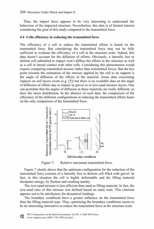
Figure 7: Relative maximum transmitted force.
Figure 7 clearly shows that the optimum configuration for the reduction of the transmitted force consists of a laterally free to deform cell filled with gravel. In fact, in this situation the cell is highly deformable and the filling material dissipates energy, by friction and crushing mainly. The tyre-sand mixture is less efficient than sand as filling material. In fact, the tyre-sand ratio of this mixture was defined based on static tests. This criterion appears not to be satisfactory for dynamical loadings. The boundary conditions have a greater influence on the transmitted force than the filling material type. Thus, optimising the boundary conditions seems to be an interesting alternative to reduce the transmitted force at the structure scale.
© 2008 WIT PressWIT Transactions on the Built Environment, Vol 98, www.witpress.com, ISSN 1743-3509 (on-line)
204 Structures Under Shock and Impact X

5 Numerical simulation
A numerical model of cells filled with gravel was developed using DEM, [6]. Gravels are modelled by unbreakable clusters of spheres. The shape and size of these clusters are closed to gravel ones. The double twisted hexagonal wire mesh is modelled by a set of particles located at the nodes of the mesh. The calibration and validation of the model were performed under static loading paths. Then, impacts were simulated. Numerical results show a good agreement with experimental ones, for both FD and RC conditions, as presented in figure 8 in the case of a FD cell. The model is robust whatever the loading path. This validation of the proposed cell model allows considering it for integration in the whole structure modelling, [7].
6 Conclusion
In order to investigate the behaviour of geo-cells as components of rock fall protection dykes a series of impact test by a 250 kg spherical boulder was performed.
Figure 8: Simulation of an impact on a FD gravel cell.
The response of the cell was evaluated thanks to the impact force and to the force transmitted by the cell to its support. The efficiency is evaluated according to the minimization of the transmitted force. Based on this criterion, the optimum geo-cell consists of a cell filled with coarse granular and laterally free to deform. The coarse granular filling material cell appeared to be the most efficient whatever the cell boundary conditions. Nevertheless, the transmitted force based criterion is not sufficient to evaluate the ability of a cell to reduce the effort transmitted in the impacted dyke. New developments are necessary to take into account the diffusion trough the structure. More over, these experiments allowed validation of a DEM model of cells filled with coarse granular material.
© 2008 WIT PressWIT Transactions on the Built Environment, Vol 98, www.witpress.com, ISSN 1743-3509 (on-line)
Structures Under Shock and Impact X 205
Acknowledgements
The authors are grateful to the PGRN (Natural Hazard Pole of Grenoble) from the General Council of Isère for their financial support, and to the research consortium VOR (Risk Vulnerability of Structures) for providing us with the experimental site.
References
[1] Lambert, S., Comportement mécanique de géo-cellules – application aux constituants de merlons pare-blocs cellulaires. Phd Thesis, University Joseph Fourier, Grenoble, in French, 2007.
[2] Gotteland, P., Lambert, S. & Balachowski, L., Strength characteristics of tyre chips-sand mixtures. Studia geotechnica et mechanica, 27(1), pp. 55–66, 2005.
[3] Radjai, F., Wolf, D. E., Jean, M. & Moreau, J.-J., Bimodal character of stress transmission in granular packings. Physical Review Letters, 80(1), pp. 61–64, 1998.
[4] Bathurst, R. J. & Karpurapu, R., Large-scale triaxial compression testing of geocell-reinforced granular soils. Geotechnical testing journal, 16, pp. 296–303, 1993.
[5] Montani Stoffel, S., Sollicitation dynamique de la couverture des galeries de protection lors de chutes de blocs. Phd Thesis, EPFL, Lausanne, in French, 1998.
[6] Bertrand, D., Nicot, F., Gotteland, P. & Lambert, S., Modelling a geo-composite cell using discrete analysis. Computers and Geotechnics, 32, pp. 564–577, 2005.
[7] Nicot, F., Gotteland, P., Bertrand, D. & Lambert, S., Multi-scale approach to geo-composite cellular structures subjected to rock impacts. International Journal for Numerical and Analytical Methods in Geomechanics, 31, pp. 1477–1515, 2007.
© 2008 WIT PressWIT Transactions on the Built Environment, Vol 98, www.witpress.com, ISSN 1743-3509 (on-line)
206 Structures Under Shock and Impact X