IMPACT ANALYSIS AND COMPARATIVE STUDY FOR DIFFERENT ... · IMPACT ANALYSIS AND COMPARATIVE STUDY...
15
September 2017, Volume 4, Issue 09 JETIR (ISSN-2349-5162) JETIR1709031 Journal of Emerging Technologies and Innovative Research (JETIR) www.jetir.org 161 IMPACT ANALYSIS AND COMPARATIVE STUDY FOR DIFFERENT COMPOSITE MATERIAL FOR BULLET PROOF VEST 1 Ganesh Midgule 1 MTech Research Scholar, 1 M-Tech Student dept CAD/CAM, 1 Narayana Technical Campus, Telangana, India[Affiliated to JNTU, Approved by AICTE] Abstract —The Response of a material impacted by projectiles especially bullets, or blast fragments, is extremely important in determining the range of impact it can su stain. As explicit finite element codes improve and advances material models become available, the hydro codes find more widespread application in many industries. In this thesis, a study of ballistic response is implemented using simulation of thin metal targets in Explicit Dynamics in Ls-Dyna software. Further in the study an attempt has been made to study the response of composite targets to the projectile impact. For the composite target, a finite element model is implemented. In this project, impact analysis of bullet on composite material for bullet proof vest are discussed in order to develop the feasibility of composite ballistic impact loading. This topic is providing a brief overview of bullet impact on composite analysis using Ls-Dyna software. Kevlar-Epoxy is used in an armor applications for bulletproof purposes. This project is providing guidance for engineer’s guidance w hile working with Kevlar-Epoxy and S2 glass. In response to the reduce weight of armor, easy for wear. Index Terms — Impact analysis, Bullet proof vest, composite. ________________________________________________________________________________________________________ 1 LITERATURE SURVEY Priyawart Lather, ―Analysis of composite materials used in bullet proof vests using fem technique‖, International Journal of Scientific & Engineering Research, May-2013 This shows studying various composite materials used in bullet-proof vests and to analyze their effectiveness by using FEM technique. Hence obtained data would be utilized for designing an optimized bullet- proof vest. When a handgun bullet strikes body armor, it is caught in a "web" of very strong fibers. M. Grujicic, P.S. Glomski, ―Material Modeling and Ballistic-Resistance Analysis of Armor-Grade Composites Reinforced with High-Performance Fibers‖, ASM International, January 2009. The present model is constructed in such a way that it can be readily integrated into commercial finite element programs like ANSYS/Autodyne. To validate the model, a series of transient nonlinear dynamics computational analyses of the transverse impact of armor-grade composite laminates with two types of bullets/projectiles is carried out and the computational res ults compared with their experimental counterparts.A A Ramadhan , ―The Influence of impact on Composite Armor System Kevlar-29/polyester-Al2O3‖,International Conference on Mechanical Engineering Research, 2011.An experimental investigation of high velocity impact responses of composite laminated plates using a helium gas gun has been presented in this paper. The aim of this study was to develop the novel composite structure that meets the specific requirements of ballistic resistance which used for body protections, vehicles and other applications. Thus the high velocity impact tests were performed on composite Kevlar-29 fiber/polyester resin with alumina powder (Al2O3). 2 INTODUCTION 2.1 COMPOS ITE A broad definition of composite is a two or more chemically distinct materials which when combined have improved properties over the individual materials. Composites are a combination of two materials in which one of the material is called the reinforcing phase, is in the form of fibers, Due to their high strength to weight ratios, laminated composite materials have found extensive applications in the construction of mechanical, aerospace, marine, protective gear and automotive structures [1]. The purpose of the ballistic protective materials is not to just stop the speeding bullets but to protect the individual from fragmenting devices as well, i.e. from grenades, mortars, artillery shells, and improvised explosive devices. We should note that the injury caused to the civilians is mainly due to two factors: • High velocity bullets from rifles, machine guns which are mainly shot from a long range. • Low velocity bullets from hand guns which are shot from close range [4]. 3 INTRODUCTION TO ARMOR S YSTEMS Military systems especially supporting the ground forces are being transformed to move faster, more agile and more mobile as to counteract the warfare tactics. Bomb attacks on armored vehicles claimed lives of Defense troops. As a result, an increased demand for improved armor has led to the development of new armor materials. Already in some fields Polymer Matrix
Transcript of IMPACT ANALYSIS AND COMPARATIVE STUDY FOR DIFFERENT ... · IMPACT ANALYSIS AND COMPARATIVE STUDY...

September 2017, Volume 4, Issue 09 JETIR (ISSN-2349-5162)
JETIR1709031 Journal of Emerging Technologies and Innovative Research (JETIR) www.jetir.org 161
IMPACT ANALYSIS AND COMPARATIVE
STUDY FOR DIFFERENT COMPOSITE
MATERIAL FOR BULLET PROOF VEST 1Ganesh Midgule
1MTech Research Scholar,
1M-Tech Student dept CAD/CAM,
1Narayana Technical Campus, Telangana, India[Affiliated to JNTU, Approved by AICTE]
Abstract—The Response of a material impacted by projectiles especially bullets, or blast fragments, is extremely important in
determining the range of impact it can sustain. As explicit finite element codes improve and advances material models become available, the
hydro codes find more widespread application in many industri es. In this thesis, a study of ballistic response is implemented using
simulation of thin metal targets in Explicit Dynamics in Ls-Dyna software. Further in the study an attempt has been made to study the
response of composite targets to the projectile impact. For the composite target, a finite element model is implemented.
In this project, impact analysis of bullet on composite material for bullet proof vest are discussed in order to develop the feasibility of
composite ballistic impact loading. This topic is providing a brief overview of bullet impact on composite analysis using Ls-Dyna software.
Kevlar-Epoxy is used in an armor applications for bulletproof purposes. This project is providing guidance for engineer’s guidance w hile
working with Kevlar-Epoxy and S2 glass. In response to the reduce weight of armor, easy for wear.
Index Terms — Impact analysis, Bullet proof vest, composite.
________________________________________________________________________________________________________
1 LITERATURE S URVEY
Priyawart Lather, ―Analysis of composite materials used in bullet proof vests using fem technique‖, International Journal of
Scientific & Engineering Research, May-2013 This shows studying various composite materials used in bullet -proof vests and to
analyze their effect iveness by using FEM technique. Hence obtained data would be utilized for designing an optimized bullet -
proof vest. When a handgun bullet strikes body armor, it is caught in a "web" of very strong fibers. M. Grujicic, P.S. Glomski,
―Material Modeling and Ballistic-Resistance Analysis of Armor-Grade Composites Reinforced with High-Performance Fibers‖,
ASM International, January 2009. The present model is constructed in such a way that it can be readily integrated into
commercial finite element programs like ANSYS/Autodyne. To validate the model, a series of transient nonlinear dynamics
computational analyses of the transverse impact of armor-grade composite laminates with two types of bullets/projectiles is
carried out and the computational results compared with their experimental counterparts.A A Ramadhan , ―The Influence of
impact on Composite Armor System Kevlar-29/polyester-Al2O3‖,International Conference on Mechanical Engineering Research,
2011.An experimental investigation of high velocity impact responses of composite laminated plates using a helium gas gun has
been presented in this paper. The aim of this study was to develop the novel composite structure that meets the specific
requirements of ballistic resistance which used for body protections, vehicles and other applications. Thus the high velocity
impact tests were performed on composite Kevlar-29 fiber/polyester resin with alumina powder (Al2O3).
2 INTODUCTION
2.1 COMPOS ITE
A broad definition of composite is a two or more chemically distinct materials which when combined have improved
properties over the individual materials. Composites are a combination of two materials in which one of the material is called the
reinforcing phase, is in the form of fibers, Due to their high strength to weight ratios, laminated composite materials have found
extensive applications in the construction of mechanical, aerospace, marine, protective gear and automotive structures [1]. T he
purpose of the ballistic protective materials is not to just stop the speeding bullets but to protect the individual from fragmenting
devices as well, i.e. from grenades, mortars, artillery shells, and improvised exp losive devices. We should note that the injury
caused to the civilians is mainly due to two factors:
• High velocity bullets from rifles, machine guns which are main ly shot from a long range.
• Low velocity bullets from hand guns which are shot from close range [4].
3 INTRODUCTION TO ARMOR S YSTEMS
Military systems especially supporting the ground forces are being transformed to move faster, more agile and more mobile
as to counteract the warfare tactics. Bomb attacks on armored vehicles claimed lives of Defense troops. As a result, an incre ased
demand for improved armor has led to the development of new armor materials. A lready in some fields Polymer Matrix

September 2017, Volume 4, Issue 09 JETIR (ISSN-2349-5162)
JETIR1709031 Journal of Emerging Technologies and Innovative Research (JETIR) www.jetir.org 162
Composites, Ceramics and Metal mobility. Research is still going on in this field to completely replace the armor shield with
composite materials which offer good strength to weight ratios [5].
3.1 INTRODUCTION TO BODY ARMOR
Throughout history, lightweight and flexib le materials have been sought to reduce the weight of body armor systems to
enhance mobility, while providing protection against specified threats. Early materials included leather and even silk, which were
used in conjunction with metal p lates to provide the needed protection in making vests. These vests provided protection against
bomb and grenade fragments, which accounted for the high majority of in juries and deaths among soldiers. Although nylon and
E-glass fibers continue to find some use today due to their low cost, high performance fibers are now the standard for most fib er
reinforced armor applications. High performance fibers are typically used in the form of woven fabrics for vests and for helmets.
Figure 3 shows the Interceptor vest and composite [5].
Fig.1 bulletproof vest
3.2 ARMOR CLASSIFICATIONS FOR BALLISTIC-RES IS TANT ARMOR
There are six fo rmal armor classification types, as well as a seventh special type, as follows [4]:
Type I (.22 LR; .380 ACP).
This armor protects against .22 long rifle lead round nose (LR LRN) bullets, with nominal masses of 2.6 g (40 gr),
impacting at a minimum velocity of 320 m/s (1050 ft/s) or less, and against .380 ACP full metal jacketed round nose (FMJ RN),
with nominal masses of 6.2 g (95 gr), impact ing at a minimum velocity of 312 m/s (1025 ft/s) or less. Type I body armor is light.
This is the min imum level of protection every officer should have, and the armor should be routinely worn at all t imes while on
duty. Type I body armor was the armor issued during the NIJ demonstration project in the mid -1970s. Most agencies today,
however, because of increasing threats, opt for a higher level of protection.
Type II-A (9mm; .40 S&W).
This armor protects against 9mm full metal jacketed round nose (FMJ RN) bullets, with nominal masses of 8.0 g (124
gr), impacting at a min imum velocity of 332 m/s (1090 ft/s) or less, and .40 S&W caliber full metal jacketed (FMJ) bullets, with
nominal masses of 11.7 g (180 gr), impact ing at a minimum velocity of 312 m/s (1025 ft/s) or less. It also provides protectio n
against Type I threats. Type II-A body armor is well suited for full-time use by police departments, particularly those seeking
protection for their officers from lower velocity 9mm and 40 S&W ammunition.
Type II (9mm; .357 Magnum).
This armor protects against 9mm full metal jacketed round nose (FMJ RN) bullets, with nominal masses of 8.0 g (124
gr), impact ing at a min imum velocity of 358 m/s (1175 ft/s) or less, and .357 Magnum jacketed soft point (JSP) bullets, with
nominal masses of 10.2 g (158 gr), impact ing at a minimum velocity of 427 m/s (1400 ft/s) or less. It also provides protection
against Type I and Type IIA threats. Type II body armor is heavier and more bulky than either Types I or II -A. It is worn full t ime
by officers seeking protection against higher velocity .357 Magnum and 9mm ammunit ion.
Type III-A (High Velocity 9mm; .44 Magnum).
This armor protects against 9mm full metal jacketed round nose (FJM RN) bullets, with nominal masses of 8.0 g (124
gr), impacting at a minimum velocity of 427 m/s (1400 ft/s) or less, and .44 Magnum jacketed hollow poin t (JHP) bullets, with
nominal masses of 15.6 g (240 gr), impact ing at a minimum velocity of 427 m/s (1400 ft/s) or less. It also provides protection
against most handgun threats, as well as the Type I, II-A, and II threats. Type III-A body armor provides the highest level of
protection currently available from concealable body armor and is generally suitable for routine wear in many situations.
However, departments located in hot, humid climates may need to evaluate the use of Type III -A armor carefu lly.
Type III (Rifles).
This armor protects against 7.62mm full metal jacketed (FMJ) bullets (U.S. military designation M80), with nominal
masses of 9.6 g (148 gr), impact ing at a minimum velocity of 838 m/s (2750 ft/s) or less. It also provides protection again st Type I

September 2017, Volume 4, Issue 09 JETIR (ISSN-2349-5162)
JETIR1709031 Journal of Emerging Technologies and Innovative Research (JETIR) www.jetir.org 163
through III-A threats. Type III body armor is clearly intended only for tactical situations when the The ballistic fabric materials
can be arranged to provide effective protection. Each body armor developer has its own method when developing prot ective
systems. The fibers are usually p lain woven together, although there are other methods of weaving that are used. Some armors use
one single material stacked in mult iple layers, others use several types of materials. Each layer of material can be comprised of
varying directional fibers. Additional layers of material increase the ballistic resistance and blunt trauma protection, but the
weight is also increased. Several stitching methods are employed to hold the layers together. For example, a bias stitch can be
applied around threat warrants such protection, such as barricade confrontations involving sporting rifles.
Type IV (Armor Piercing Rifle).
This armor protects against .30 caliber armor p iercing (AP) bullets (U.S. military designation M2 AP), w ith nominal
masses of 10.8 g (166 gr), impact ing at a min imum velocity of 869 m/s (2850 ft/s) or less. It also provides at least single -hit
protection against the Type I through III threats. Type IV body armor provides the highest level of protection curre ntly available.
Because this armor is intended to resist ―armor piercing‖ bullets, it often uses ceramic materials. Such materials are brittle in
nature and may provide only single-shot protection, since the ceramic tends to break up when struck. As with Type III armor,
Type IV armor is clearly intended only for tactical situations when the threat warrants such protection.
Special type.
A purchaser who has a special requirement for a level of protection other than one of the above standard threat levels
should specify the exact test rounds and minimum impact velocities to be used and indicate that this standard shall govern in all
other respects.
3.3 MANUFACTURING AND TES TING OF BALLISTIC BODY ARMOR
Ballistic resistant body armor is developed for a variety of s cenarios and levels of protection. Factors that are considered
when developing body armor include weight (i.e. areal density), type of bullet, bullet velocities, and comfort. The idea behind
stopping a bullet is to reduce its energy. When the bullet hits the ballistic resistant system, it absorbs and disperses the energy of
the bullet by deforming it into a mushroom shape. Typically, military ballistic armor consists of soft and rigid components. The
soft armor forms the flexib le, p rotective vest. It contains several layers of ballistic fabric material(s). The rig id armor is used for
enhanced protection in specific areas, normally this is over the chest region to protect vital organs. The rigid armor is in the form
of a plate that is inserted into a pocket of the vest. The entire body armor system has a carrier, usually made of nylon that has the
sole purpose of supporting the ballistic material and securing the armor to the body for correct positioning and comfort the
perimeter of the materials. There are several other forms of stitching which include rows of parallel or overlapped vertical,
horizontal and d iagonal lines. Stitching of ballistic materials has been shown to slightly improve ballistic integrity and en hance
protection against blunt trauma [4].
Manufacturing process
Some bulletproof vests are custom-made to meet the customer's protection needs or size. Most, however, meet standard
protection regulations, have standard clothing industry sizes (such as 38 long, 32 short), and are sold in quantity Bulletproof vests
undergo many of the same tests a regular piece of clothing does. The fiber manufacturer tests the fiber and yarn tensile stre ngth,
and the fabric weavers test the tensile strength of the resultant cloth. Nonwoven Spectra is also tested for t ensile strength by the
manufacturer. Body armor manufacturers test the panel material (whether Kevlar or Dyneema) for strength, and production
quality control requires that trained observers inspect the vests after the panels are sewn and the vests complet ed. Bulletproof
vests, unlike regular clothing, must undergo stringent protection testing as required. Not all bulletproof vests are alike. Some
protect against lead bullet at low velocity, and some protect against full metal jacketed bullets at high veloc ity [4].
Fig.2. Manufacturing process of bulletproof vest

September 2017, Volume 4, Issue 09 JETIR (ISSN-2349-5162)
JETIR1709031 Journal of Emerging Technologies and Innovative Research (JETIR) www.jetir.org 164
Quality control
Bulletproof vests undergo many of the same tests a regular piece of clothing does. The fiber manufacturer tests the fiber
and yarn tensile strength, and the fabric weavers test the tensile strength of the resultant cloth. Nonwoven Spectra is also tested for
tensile strength by the manufacturer. Body armor manufacturers test the panel material (whether Kevlar or Dyneema) fo r strength,
and production quality control requires that trained observers inspect the vests after the panels are sewn and the vests comp leted.
Bulletproof vests, unlike regular clothing, must undergo stringent protection testing as required [4].
Testing
Fig.3. Gas gun tunnel to test the s pecimens
Bulletproof vests are tested both wet and dry. This is done because the fibers used to make a vest perform differently
when wet. Testing (wet or dry) a vest entails wrapping it around a modeling clay dummy. A firearm of the correct type with a
bullet of the correct type is then shot at a velocity suitable for the classification of the vest. Each shot should be three inches (7.6
centimeters) away from the edge of the vest and almost two inches from (five centimeters) away from previous shots. Six shots
are fired, two at a 30-degree angle of incidence, and four at a O-degree angle of incidence. One shot should fall on a seam. This
method of shooting forms a wide triangle of bullet holes. The vest is then turned upside down and shot the same way, this time
making a narrow triangle of bullet holes [4].
The instrumented impact test equipment used in this study was a gas gun impact tester M. T. H. Sultan [12] shown in
Figure 4. The general features of the testing apparatus are shown in Figure has been designed in order to launch the project i le.
The main components of the gas gun are the 2200 Psi pressure tank, the purpose-built "ring section for compressed gas, the 4 m
long smooth barrel and (60, 60 and 40 cm) dimensions of box chamber to hold the specimen inside this box which it has (60 x 60
cm) framing window to observe the behavior of target and bullet by photography high speed camera (200,000 fps) for this work
[7].
3.4 MATERIAL US ED
There are several types of ballistic fabrics that are used today:
Structure & properties
When Kevlar is spun, the resulting fiber has a tensile strength of about 3 620 MPa, and a relative density of 1.44. The
polymer owes its high strength to the many inter-chain bonds. These inter-molecular hydrogen bonds form between the carbonyl
groups and NH centers. Additional strength is derived from aromat ic stacking interactions between adjacent strands. These
interactions have a greater influence on Kevlar than the van der Waals interactions and chain length that typically influence the
properties of other synthetic polymers and fibers such as Dyneema. The presence of salts and cert ain other impurities, especially
calcium, could interfere with the strand interactions and caution is used to avoid inclusion in its production. Kevlar's stru cture
consists of relatively rigid molecules which tend to form mostly planar sheet -like structures rather like silk protein [4].
Thermal properties
Kevlar maintains its strength and resilience down to cryogenic temperatures (-196°C); indeed, it is slightly stronger at
low temperatures. At higher temperatures the tensile strength is immediately reduced by about 10-20%, and after some hours the
September 2017, Volume 4, Issue 09 JETIR (ISSN-2349-5162)
JETIR1709031 Journal of Emerging Technologies and Innovative Research (JETIR) www.jetir.org 165
strength progressively reduces further. For example at 160°C about 10% reduction in strength occurs after 500 hours. At 260°C
50% strength reduction occurs after 70 hours [4].
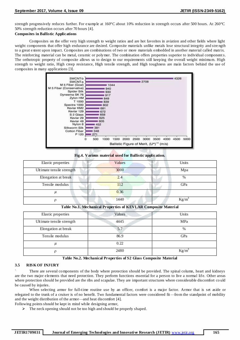
Composites in Ballistic Applications
Composites on the offer very high strength to weight ratios and are hot favorites in aviation and other fields where light
weight components that offer high endurance are desired. Composite materials unlike metals lose structural integrity and stre ngth
to a great extent upon impact. Composites are combinations of two or more materials embedded in another material called matrix.
The reinforcing material can be metal, ceramic or polymer. The combination offers properties superior to individual component s.
The orthotropic property of composite allows us to design to our requirements still keep ing the overall weight minimum. High
strength to weight ratio, High creep resistance, High tensile strength, and High toughness are main factors behind the use of
composites in many applications [3].
Fig.4. Various material used for Ballistic application.
Elastic properties Values Units
Ult imate tensile strength 3000 Mpa
Elongation at break 2.4 %
Tensile modulus 112 GPa
𝜇 0.36
1440 Kg/m3
Table No.1. Mechanical Properties of KEVLAR Composite Material
Elastic properties Values Units
Ult imate tensile strength 4445 MPa
Elongation at break 5.7 %
Tensile modulus 86.9 GPa
𝜇 0.22
2480 Kg/m3
Table No.2. Mechanical Properties of S2 Glass Composite Material
3.5 RIS K OF INJURY
` There are several components of the body where protection should be provided. The spinal column, heart and kidneys
are the two major elements that need protection. They perform functions essential for a person to live a normal life. Other areas
where protection should be provided are the ribs and scapulae. They are important structures where considerable discomfort co uld
be caused by injuries.
When selecting armor for full-t ime routine use by an officer, comfort is a major factor. Armor that is set aside or
relegated to the trunk of a cruiser is of no benefit. Two fundamental factors were considered fit —from the standpoint of mobility
and the weight distribution of the armor—and heat discomfort [4].
Following points should be kept in mind while designing armor,
The neck opening should not be too high and should be properly shaped.

September 2017, Volume 4, Issue 09 JETIR (ISSN-2349-5162)
JETIR1709031 Journal of Emerging Technologies and Innovative Research (JETIR) www.jetir.org 166
The shoulder, neck, and armholes should be feathered to minimize bulk and maximize comfort at these areas, but still
not reduce protection.
The shoulder straps should be wide enough for comfort and to distribute the weight of the armor, but not so wide as to
restrict movement
Seam construction of the armor should allow maximum flexib ility and yet maintain p rotective coverage. The armor
should permit size adjustment while retaining protective integrity for the sides of the torso.
The carrier fo r the armor material should have a tail that can be tucked into the pants to prevent the armor from rid ing
up.
The armor should be as light as possible, while still p roviding protection against the threat that is most prevalent in the
geographical area of use.
The length of the front of the armor should not be too long; otherwise, it will be pushed up into the throat when the
officer sits or bends.
The armor should be wide enough to allow the front panel to overlap the back panel. The armholes of the armor should
not be too small.
The concealed undergarments for officers should conform to the anatomy. The seam construction for such garments that
include seams is critical. It is very important that the joined pieces overlap each other a min imum of 1 inch. Part icular
attention should be paid to the length of the garment, which is a frequent problem. The adjustment straps for the
undergarment may be fastened to the back to improve the overall appearance of the uniform. (4)
4 MECHANICS OF PENETRATION
4.1 INTRODUCTION TO PENETRATION OF MECHANICS
The penetration mechanics, also known as the impact and penetration mechanics, is an interdiscip linary subject. A
comprehensive discussion of the relevant background would be quite extensive. However, this thesis focuses on the ballistic
response during the impact.
Penetration and failure in metal targets
Metals are isotropic materials i.e., having same properties in all directions. Models of penetration and perforations are
based on laws of conservation and compatibility. As an Impact occurs, the kinetic energy of the projectile is imparted to the plate.
Some of the energy is used to deform the plate. Other energy is given off as light and heat, the remainder of the energy is
imparted to the fragments as kinetic energy. Measuring or determin ing each of these energies is very difficult .For penetration and
perforation analysis, the only important aspect is to predict the kinetic energy (i.e. mass and velocity) of the fragments. Once this
kinetic energy is determined, conservation of mass and energy, sometimes in terms of momentum, is applied to the
projectile/target system. The analysis is still quite complex because the events that occur a t the projectile/ target interface are
somewhat unknown. Although many studies have been performed, only highly controlled velocities, shapes, sizes and trajectorie s
have been examined. As a result, numerous approximations and assumptions must be made in o rder to apply to these analyses to
fragments. Impact is a much localized phenomenon. Stress and strain effects are usually limited to within 3-6 projectile diameters
of the impacted zone. Impacted target materials may fail by a combination of several modes including spalling, plugging,
petaling, ductile or brittle fracture, and adiabatic shearing. Figure shows some of these failure modes [6].
Fracture due to init ial stress wave Radial fracture behind in itial wave in a brittle

September 2017, Volume 4, Issue 09 JETIR (ISSN-2349-5162)
JETIR1709031 Journal of Emerging Technologies and Innovative Research (JETIR) www.jetir.org 167
Fig.5 Common failures occurring in projectile impact [6]
A target is considered thick if the distal boundary is influential only after substantial travel of the projectile into the
target. For thin targets distal side responds immediately for impact on the frontal side. Spalling is tensile failure of the target
material due to the reflection of the initial compressive waves from the far side of the target. Failure by spalling can occu r on
either the front or back of a target and is characterized by the format ion of petals or ejects.
In ductile failure, the impact impulse overcomes the peripheral dynamic shear strength of the target material, pushing it
outward and toward the impact surface to form a crater that is much larger than the projectile diameter. At the same time, th e
projectile pushes into the target, and there is hydrodynamic erosion and inversion of the penetrator material against the preceding
face of the target [6].
The penetration process due to high-velocity impact can be represented by four phases: transient, primary penetration,
secondary penetration, and recovery. The first, or transient, phase is characterized by a very short pressure spike and occurs when
the projectile first contacts the target surface. The primary penetration phase is described as the period during which the p rojectile
acts as a contributing force, imparting its kinetic energy to the target in a hydrodynamic manner. The secondary phase (more than
one phase may occur simultaneously), sometimes referred to as cavitations, begins after the projectile is completely deformed and
effectively removed from the system as a source of energy. It is marked by target deformation not caused directly by the KE of
the projectile material. Instead, the energy density behind the expanding shock wave continues to deform the target material. The
fourth, or recovery, phase refers to the period during which the crater recovers or contracts slightly. Material just below t he target
surface anneals and re-crystallizes [6].
Projectile failu re occurs simultaneously with target failure. Thus, penetration models involve both things. The projectiles
deform and flatten/spread out as they strike the target, generating high resisting contact forces. For low L/D ratios, either model
gave reasonable predictions. Expectedly, this also suggests that a combination of both phenomena actually takes place. Another
penetration model is similar to the erosion model, but of a more hydrodynamic nature. The part icular treatment here is taken from
[24]. In this model, the front end of the projectile and the impacted surface are modeled as flowing liqu ids. The regions directly
behind these surfaces are then modeled as rigid bodies. The projectile is consumed from the impact end as it penetrates the target
material and is transformed into a Further it p redicts that most of the impacted target material is displaced forward and outward by
the projectile during penetration and that a small amount is ejected backwards. Maximum strain criterion is used to show the
failure of the material. In present analysis no data is available regarding the deformation of the projectile and mass loss of the
projectile, so the projectiles deformat ion is ignored in the target. In the event of Impact there is an exchange of energy ta kes place.
plugging
Petaling rearward Petaling frontal
Spall failure (scabbing)
Fragmentation Ductile hole enlargement
September 2017, Volume 4, Issue 09 JETIR (ISSN-2349-5162)
JETIR1709031 Journal of Emerging Technologies and Innovative Research (JETIR) www.jetir.org 168
Law of Conservation is observed in any physical phenomena. Kinetic energy of the projectile is spent in raising the
internal energy and kinetic energy of the plate and some part of the energy is lost in the form of eroded material . Th is is
described by the equation (2.2), where E, IE, KE denote total energy, internal energy, kinetic energy, subscripts trans and plate
denote transmitted and related to plate. The superscript eroded denotes eroded mass. Blunt projectiles like cylinders are fou nd to
cause plugging because of pure shear failure, while the conical p rojectiles are found to cause petaling effect. The amount of
energy dissipated also differs with the geometry.
4.2 COMPOS ITE FAILURE AND DAMAGE
Composites are orthotropic materials i.e ., having different properties in perpendicular directions. Parameters which
significantly affect the properties of a composite are shape, size, orientation and distribution of the reinforcement and var ious
other features such as matrix, grain size in case of polymer matrix composites. These together with volume fraction constitute
what is called the microstructure of the composite. The orientation of the reinforcement within the matrix affects the isotropy of
the system. When the reinforcement is in the form of equiaxial particles, the composite behaves essentially as an isotropic
material whose elastic properties are independent of direction. Manufacturing process may result in different orientation of the
reinforcement and hence the loss of isotropy; thus composite becomes anisotropic in nature. High velocity impact will cause
localize compression of the composite and subsequently shearing the fibers and spalling of the resin during impact, the fibers take
the shear loading. Once the projectile has slowed, the composite deforms causing fiber stretching, pullout, and delaminating of the
composite layers (plies) and thus lower load carrying ability [2].
Fig.6 Rigid projectile impacting a composite
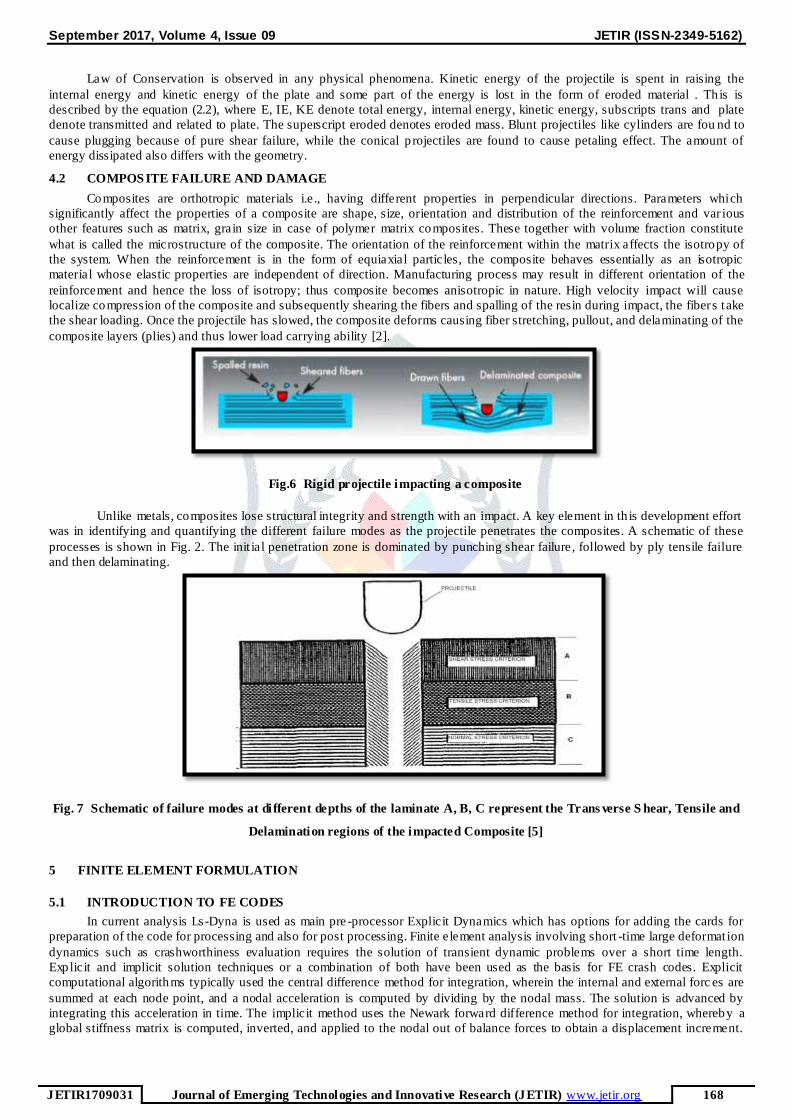
Unlike metals, composites lose structural integrity and strength with an impact. A key element in th is development effort
was in identifying and quantifying the different failure modes as the projectile penetrates the composites. A schematic of these
processes is shown in Fig. 2. The init ial penetration zone is dominated by punching shear failure, followed by ply tensile failure
and then delaminating.
Fig. 7 Schematic of failure modes at di fferent depths of the laminate A, B, C represent the Trans verse S hear, Tensile and
Delamination regions of the impacted Composite [5]
5 FINITE ELEMENT FORMULATION
5.1 INTRODUCTION TO FE CODES
In current analysis Ls-Dyna is used as main pre -processor Explicit Dynamics which has options for adding the cards for
preparation of the code for processing and also for post processing. Finite element analysis involving short -time large deformat ion
dynamics such as crashworthiness evaluation requires the solution of transient dynamic problems over a short time length.
Explicit and implicit solution techniques or a combination of both have been used as the basis for FE crash codes. Explicit
computational algorithms typically used the central difference method for integration, wherein the internal and external forc es are
summed at each node point, and a nodal acceleration is computed by dividing by the nodal mass. The solution is advanced by
integrating this acceleration in time. The implicit method uses the Newark forward difference method for integration, whereby a
global stiffness matrix is computed, inverted, and applied to the nodal out of balance forces to obtain a displacement increment.

September 2017, Volume 4, Issue 09 JETIR (ISSN-2349-5162)
JETIR1709031 Journal of Emerging Technologies and Innovative Research (JETIR) www.jetir.org 169
The advantage of this method is that time-step size may be selected by the user. The disadvantage is the large numerical effort
required to form, store, and factorize the stiffness matrix. The major practical difference between the explicit and the implicit
solution technique is the requirement on the time step size, ∆t.
Impact Loading: If the time of load applicat ion is less than 0.5 times the fundamental period of the mechanical system,
the loading is defined as impact. The static methods of stress, strain, and deflection analysis are meaningless under impact
conditions. This is due to propagation, reflection, and interference of elastic/plastic waves traveling within the engineering solid.
Accurate calculations of stresses and strains most of be based on wave analysis methods, which are exceedingly complex for
practical use, and thus must be solved for a limited number of simple cases. Other methods s uch as contact mechanics, energy
methods, and FEA must be used to estimate the effects of impact analysis on mechanical systems that exhibit complexity [2].
Reasons for using the FEA Method in High Speed and Impact Loading conditions are analytical method s are useful in
making predictions and understanding the dominant features of impact problems, g iven the engineering problem can be simplifie d
to a simple geometry. Thus, geometry complexity limits the use of analytical methods. In general, high -speed/impact problems
present a complexity of geometry, stiffness, mass distribution, impact angle, contact areas, and multip le impacts. In these c ases,
the only tool for complex analysis of impact or high-speed is some form of numerical methodology. Two classes of numerical
methods exist for the analysis of impact problems- the fin ite difference method and the finite element analysis method. The
fin ite difference method has the advantage of examin ing hypervelocity (high velocity) impacts involving severe damage or p lastic
flow and analogous to fluid flow/elastic deformation. FEA is applicable to slower-impact scenarios and as the advantage in
addressing irregular geometries and boundary conditions.
5.2 FINITE ELEMENT MODELING OF PROJECTILE IMPACT MODEL
MODELING DETAILS
In this analysis the plate material is KEVLAR EPOXY and S2 glass and projectile (bullet) material is Tool Steel. Actual
plate’s dimensions are 500mm X 300mm X 4 mm. Finite element model is prepared in Explicit Ls - dyna. In impact event the
damaged area is localized so one way biased meshing is used.
Geometry
For the analysis of impact of bullet on bullet proof vest made up of composite material. For the bulletproof vest is made
up of Kevlar-Epoxy and S2 glass composite material for the analysis front area of vest is considered as rectangular shape with
dimension 500mm X 300mm X 4 mm. and the dimension of bullet as shown in fig. below. According to this dimension front of
vest and bullet is modeled on pro-e.
Fig. 4.8 Modeling of bulletproof vest (plate) and bullet
Material properties
In the present model bullet proof vest is of Kevlar-Epoxy and S2glass material and its properties are defined above in
table no.1. The bullet is made up of steel material. In the Ls dyna software properties of Kevlar -Epoxy and S2 glass are inbuilt
and the properties of steel as well.
Fe modeling:-
Hex meshing prefer for the plate and tetra mesh prefer for bullet. For the composite material we model four layer across
the thickness. Average element size for the mesh is 10 mm. At the location of impact for getting good contact behavior we
reduced up to 1 mm. For modeling the bullet we prefer Tetra mesh with 1 mm Average size. Hex meshing we prefer element
formation 2 and for the tetra meshing we prefer it 10 element formation.
According to input provided from material details we assign the different material to component and check the results.
Kevlar Epoxy and S2 g lass are two composite material which are very strong for the sustain impact energy .According to cost and
application, St rengths we prefer the different class of Kevlar Epoxy and S2 g lass.
There is high impact velocity bullet impact on plate so prefer Surface to Surface contact to find out the Resultant force of
that component .Automatic means Single surface contact is assigned for taking dynamic action of component where required In
that contact we prefer all components. Interior contacts is for solid elements .For different material have different Strength like

September 2017, Volume 4, Issue 09 JETIR (ISSN-2349-5162)
JETIR1709031 Journal of Emerging Technologies and Innovative Research (JETIR) www.jetir.org 170
hard and soft parts comes in dynamic motion then there is chances of node shootout in mesh the run will terminates.so we assign
the interior contacts for the solids elements. Mesh model is shown below,
Fig. 8 FE Mesh model of bullet and plate
Loading and boundary condition:-
Fig. 9 Loading and boundary condition
Above figure shows Loading and boundary condition apply for the load case .According different load cases there is
change initial velocity and material properties. Above figure b lack arrows shows the fixed the outer nodes of plate in all d irect ion.
Bullet velocity impacts shown in the red circle in above figure. Various load cases for which analysis are performed are listed in
below table.
Materail / Loadcase Velocity (m/sec) Bullet Weight (gm)
Type 1 320 40
Type 2 427 158
Type 2A 332 124
Type 3 838 148
Type4 869 166
Table. 3. Load cases
5.3 RES ULTS
Impact Analysis of bullet on composite plate is done by using Ls -Dyana. Result obtained after analysis is the we observed
Elastic strain and Von –misses Stresses induced in plate.
Kevlar49 Type 1 :-
Von- Misses stress
The Stress observed in Plate is less than its material y ield limit.
The Plate is Safe for this load case .The allowable material yield stress for Kevlar 49 is 3000 Mpa. The results shows
1228.28 Mpa which is less 50 % of the yield so the material is safe for this load case.

September 2017, Volume 4, Issue 09 JETIR (ISSN-2349-5162)
JETIR1709031 Journal of Emerging Technologies and Innovative Research (JETIR) www.jetir.org 171
Fig. 10. Von-mises stress plot for Kevlar 49
Plastic Strain
The Plastic strain observed in Plate is less than its material yield limit .
The Plate is Safe for this load case .The allowable material yield strain fo r Kevlar 49 is 2.4 %.the results shows No strain means
which is less than of the yield so the material is safe for this load case. No permanent deformation observed in the plate.
Fig. 11 Plastic Strain plot for Kevlar 49
Effective Strain
Fig.12 Effective Strain plot for Kevlar 49
The observation shows there is large deformation in the plate but there is no permanent deformation .it is elastic deformat ion.
Resultant Force
The graph shows high impact of bullet on plate at the initial condition .The resultant force is increases suddenly decreases.

September 2017, Volume 4, Issue 09 JETIR (ISSN-2349-5162)
JETIR1709031 Journal of Emerging Technologies and Innovative Research (JETIR) www.jetir.org 172
Fig.13 Resultant Force plot for Kevlar 49
Energy Graph
Fig.14 Energy Graph plot for Kevlar 49
The Graph shows the Variat ion of Kinetic energy, Internal energy and Total energy with respect to time .First kinetic energy
decreases as velocity drops there is increases in Internal energy increases with deformation .The total energy remains constant.
Resultant Velocity Graph
Fig. 15 Resultant Velocity Graph for Kevlar 49
The graph observed the velocity is drops at the initial condition it is drop points of the velocity .At that velocity the stresses
increases.
S2 glass Type1:-
Von- Misses stress

September 2017, Volume 4, Issue 09 JETIR (ISSN-2349-5162)
JETIR1709031 Journal of Emerging Technologies and Innovative Research (JETIR) www.jetir.org 173
Fig.16 Von- Misses stress plot for S2 Glass
The Stress observed in Plate is less than its material y ield limit.
The Plate is Safe for this load case .The allowable material yield stress for S glass is 4445 Mpa. The results shows 1886 Mpa
which is less 50 % of the yield so the material is safe for this load case.
Plastic Strain
Fig. 17 Plastic Strain plot for S2 Glass
The Plastic strain observed in Plate is higher than its material yield limit.
The Plate is fail for this load case .The allowable material y ield strain for S2 g lass is 5.7%. The results shows high strain so there
chances of high permanent deformat ion.
Effective Plastic Strain:-
Fig. 18 Effective Plastic Strain plot for S2 Glass
The observation shows there is large deformation in the plate but there is chances of permanent deformat ion.
Resultant Force

September 2017, Volume 4, Issue 09 JETIR (ISSN-2349-5162)
JETIR1709031 Journal of Emerging Technologies and Innovative Research (JETIR) www.jetir.org 174
Fig. 19 Resultant Force plot for S2 Glass
The graph shows high impact of bullet on plate at the initial condition .The resultant force is increases suddenly decreases.
Energy Graph
Fig. 20 Energy Graph plot for S2 Glass
The Graph shows the Variat ion of Kinetic energy, Internal energy and Total energy with respect to time .First kinetic energy
decreases as velocity drops there is increases in Internal energy increases with deformation .The total energy remains constant.
Resultant Velocity Graph
Fig. 21 Resultant Velocity Graph for S2 Glass
The graph observed the velocity is drops at the initial condition it is drop points of the v elocity .At that velocity the stresses
increases. After solving number of iterat ion with material Kevlar 49 and S2 glass material with their different material properties
We observed following observations for all load cases.
5.4 OBS ERVATION TABLE:-
After performing simulation in LS-Dyna for all the load cases for the both material results are viewed in LS-Pre-post. So the
results are shown in below
Results Kevlar 49 Stress (Mpa) S2 Glass Stress (Mpa )
Type Type 1 Type2 Type2A Type3 Type4 Type 1 Type2 Type2A Type3 Type4
September 2017, Volume 4, Issue 09 JETIR (ISSN-2349-5162)
JETIR1709031 Journal of Emerging Technologies and Innovative Research (JETIR) www.jetir.org 175
Von-
Mises
Stress
1223 3006 1577 3482 4848 1886 2699 1636 2441 2457
Effective
Strain
630 1580 842 2231 3176 1133 2279 2149 1983 2036
Effective
Plastic
Strain
0 0 0 0 0 0.283 0.581 0.457 0.877 1.024
Material Allowable limit:-
Material Allowable Stress (Mpa) Plastic Strain (% )
Kevlar49 3000 2.4
S2 Glass 4445 5.7
From the observation table we can easily check strength of material with different material. According to cost, availability in the
market we choose the material for the Armor Vest. From the above table.
6 CONCLUS ION
After studying the different parameter for bullet p roof vest, while selecting the material for bullet p roof vest is to identify
the risks and levels of suitability associated with high velocity impacts on the bullet proof composite material.
After simulate the Ballistic response of thin metallic target using Finite Element software it shows that velocity of bullet
major factor for deciding the thickness for bulletproof vest.
A study was conducted on a composite Kevlar and S2 glass material to study its Ballistic response at different velocities.
Parametric studies were conducted on same model by varying mass of projectile, by varying the incident velocity, by
changing the dimensions of spherical projectile, by varying the velocity of spherical project ile, by varying the failure
strain of the target plate for same cy lindrical projectile as in validation case. Thickness of the plate was kept the same
only in case of the spherical projectile.
The Kevlar 49 for Type3 and Type 4 shows high stresses as compare to Type 2Type2A respectively.Kevlar49 for Type1,
Type2, and Type2A shows less stress than its allowable limit (3000 Mpa).It is safe for application.
The Strain observed in Kevlar49 and its Type is less than its material yield limit so it is safe for given loading and
boundary condition.
The S2 glass material and Its Type the Stress observed is less than its allowable limit (4445 Mpa ) so it is safe for given
loading and boundary condition.
The high plastic strain observed in the S2 g lass material than its allowable limit (5.7 %) So it is chances of permanent
deformation in the plate.
Kevlar 49 material having less weight as compare to S2 glass material so its weight. S2 glass material having weight for
same dimension is 1.723 t imes greater than Kevlar 49.
From above point Kevlar 49 material is best suitable as compare to S2 glass for high velocity impact having less weight
composite material.
REFFERENCES
1. David Roylance, ―Laminated composite plates‖, Massachusetts Institute of Technology Cambridge, February, 2000.
2. Priyawart Lather, ―Analysis of composite materials used in bullet proof vests using fem technique‖ International Journal
of Scientific & Engineering Research, May-2013.
3. M. Grujicic, P.S. Glomski, Material, ―Material Modeling and Ballistic-Resistance Analysis of Armor-Grade Composites
Reinforced with High-Performance Fibers‖ ,ASM International, January 2009
4. S.N.A. Safri ―Low Velocity and High Velocity Impact Test on Composite Materials – A review‖The International
Journal of Engineering and Science, 2014.
5. A A Ramadhan, ―The Influence of impact on Composite Armour System Kevlar -29/polyester-Al2O3‖, International
Conference on Mechanical Engineering Research, 2011.
6. Krishan Kumar, Ishu Monga, ―An Evaluation of Energy Absorption by Bullet Resistant Glass and its Mechanical
Properties‖, International journal for research in applied science and Engineering technology (ijraset), vol. 2 issue viii,
august 2014, Issn: 2321-9653.
7. Onyechi, Pius C., Edelugo, Sylvester O., ―Finite Element Analysis for Stress-Strain Parameter of Project ile Impeded
Glass Fibre Reinforced Po lyester (Gfrp) Composites‖, Innovative Systems Design and Engineering, Vol.4, No.13, 2013.
8. Autar K. Kaw, ―Mechanics of Composite Materials‖, Taylor and Francis group, 2006
9. Bryan Harris, ―Engineering Composite Materials‖, The Institute of Materials, London1999.
10. http://world.guns.ru/ammunit ion/revolver-cartridges-e.html
11. www.matweb.com