Imo Ace Pumps
12
ACE3 1121.02 GB Product description Std Line ACE3 Flow volume: 15-180 l/min Max differential pressure: 16 bar Applications: Lubrication, circulation and transfer Screwpump Series
Transcript of Imo Ace Pumps
AC
E3
1121
.02
GB
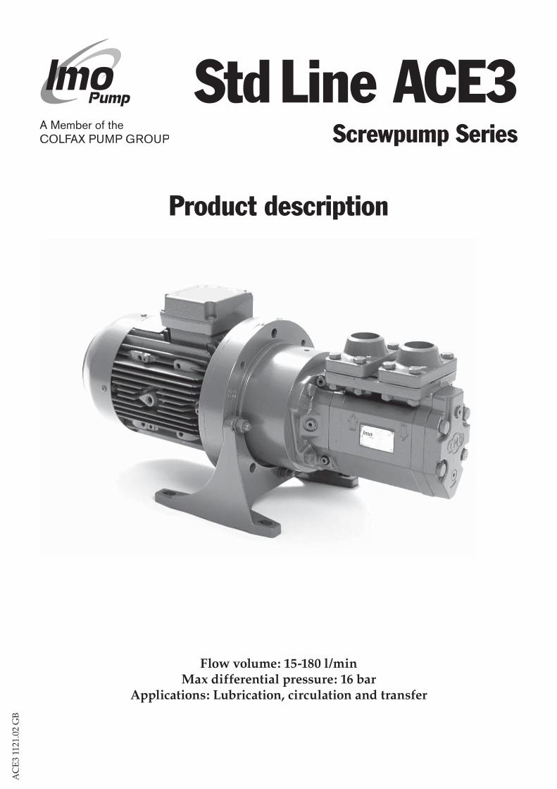
Product description
Std Line ACE3
Flow volume: 15-180 l/minMax differential pressure: 16 bar
Applications: Lubrication, circulation and transfer
Screwpump Series
2
www.imo.se
AC
E3
1121
.02
GB
Technical dataDischarge pressureMaximum discharge pressure is 16 bar.
Differential pressureMaximum differential pressure is 16 bar but is reduced at low viscosities as shown in the table below.Viscosity (cSt) 2 6 10 20Max. diff. pressure (bar) 8 12.4 15.2 16
Inlet pressureMaximum inlet pressure is 7 bar.Minimum inlet pressure is shown in the Selection guide.
DisplacementSize, lead 025L 025N 032L 032N 038K 038N 038D Displacement (cm3/r) 9.8 13.9 20.6 29.1 38.8 49.1 57.3
Pressure relief valveThe pump is equipped with an integral pres-sure relief valve with internal return, limiting the differential pressure across the pump and protecting the pump, should the discharge line be blocked. The valve is adjustable for different opening pressures. The value of the pressure limit can be set at the factory and should be adjusted at installation (see Instal-lation & Service instruction for ACE pumps). The maximum pressure ackumulation varies with pump size, speed and viscosity, but will normally not exceed 4 bar. The characteris-tic of the valve allows the valve to be used as pressure regulating valve when not too high demands on pressure modulation are requi-red. The valve has a maximum set pressure of 16 bar.
DriveThe pump is designed to be connected to an electrical motor by a flexible shaft coupling.
Max speed limitThe maximum speed is 3600 rpm. For higher speeds contact your IMO-representative.
RotationThe ACE pump is designed to operate in one rotational direction only, as standard clockwi-se when facing the shaft end.Pumps for CCW operation can be delivered on special request. For shorter periods of time, a few minutes for emptying a discharge line, the pump may be operated in reverse direc-tion, provided the back pressure is limited to 3 bar.
The Std Line (standard) ACE pumps come in two executions; Lube Line and Fuel Line. The main differens is the shaft seal design, optimi-zed for light duty and heavy duty respectivly. The pumps are used for handling non-aggres-sive fluid with sufficient lubricating proper-ties.When so required the Std Line ACE pump may be certified according to any of following classification societies: DnV, BV, LRS, ABS, RS, GL, RINA, KR, NK or CCS.
Typical applications are:• Lubrication of diesel engines, gears, gas and
steam turbines, hydro turbines and paper machines.
• Circulation for cooling and filtration in large machineries, hydraulic systems and transfor-mer oil for insulation in transformers.
• Transfer onboard ships, in oil factories, refi-neries, tank farms etc.
• Fuel supply duties for diesel engines.
Application
3
www.imo.se
AC
E3
1121
.02
GB
Material and design Lube Line Fuel LinePump body Nodular cast iron Nodular cast ironPower rotor Surface-treated steel Surface-treated steelIdler rotors Surface treated cast iron Surface treated cast ironShaft seal Carbon/Silicon Carbide Silicon Carbide/Silicon Carbide Viton elastomers Viton elastomers
For handling of fluids that may be aggressive to above materials consult your IMO-representa-tive.
Viscosity tablecSt 2 4 8 20 37 75 200 400 800 1500SSU 32.6 39.2 52.2 99.4 174 346 927 1850 3700 6940
UnitsThe following units are frequently used for specification of pumps: SI IMO USA ConversionPressure Pa (MPa) bar psi 1 bar = 14.5 psi = 0.1 MPaSpeed r/s rpm rpm 1 rpm = 0.016667 r/sViscosity mm2/s cSt SSU mm2/s = cSt (see table)Temperature °C °C °F °C = (°F-32)/1.8Length m mm inch 1 mm = 0.0394 inchFlow rate m3/s lit/min GPM 1 lit/min = 0.264 GPM
Fluid viscosityMin. viscosity, all oil types 1.6 cStLube Line (Seal version code V): Max. viscosity, lube & hydraulic oils 800 cSt Max. viscosity, fuel oils 200 cStFuel Line (Seal version code T): Max. viscosity 3 500 cSt For higher viscosity contact IMO AB.
Fluid temperatureLube Line: -20°C to 90°C.Fuel Line: -20°C to 155°C
Sound levelA typical sound level from a pump with stan-dard driver is 58 dB(A). This value refers to free field conditions at 5 bar, 2940 rpm and 40 cSt, measured according to ISO-3741.
Moment of inertiaFor bare shaft pump Size 025 032 03810-6 kgm2 20 60 140
Mounting attitudeThe ACE is mounted vertically with the shaft pointing upwards or horizontally with pipe connections facing upwards or sideways. On special request a pump for horizontal moun-ting with pipe connections facing downwards can be delivered.
4
www.imo.se
AC
E3
1121
.02
GB
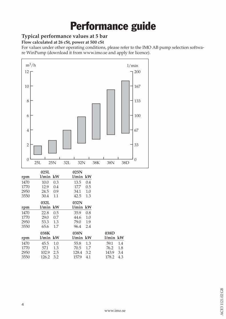
Performance guideTypical performance values at 5 barFlow calculated at 26 cSt, power at 500 cStFor values under other operating conditions, please refer to the IMO AB pump selection softwa-re WinPump (download it from www.imo.se and apply for licence).
0
2
4
6
8
10
12
0
33
67
100
133
167
200
38D38N38K32N32L25N25L
m3/h l/min
025L 025N rpm l/min kW l/min kW 1470 10.0 0.3 13.5 0.4 1770 12.9 0.4 17.7 0.5 2950 24.5 0.9 34.1 1.0 3550 30.4 1.1 42.5 1.3
032L 032N rpm l/min kW l/min kW 1470 22.8 0.5 35.9 0.8 1770 29.0 0.7 44.6 1.0 2950 53.3 1.3 79.0 1.9 3550 65.6 1.7 96.4 2.4
038K 038N 038D rpm l/min kW l/min kW l/min kW 1470 45.5 1.0 55.8 1.3 59.1 1.41770 57.1 1.3 70.5 1.7 76.2 1.82950 102.9 2.5 128.4 3.2 143.9 3.43550 126.2 3.2 157.9 4.1 178.2 4.3
5
www.imo.se
AC
E3
1121
.02
GB
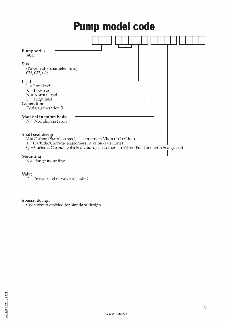
Pump model code
Pump series ACE
Size(Power rotor diameter, mm)025, 032, 038
LeadL = Low leadK = Low leadN = Normal leadD = High lead
GenerationDesign generation 3
Material in pump bodyN = Nodular cast iron
Shaft seal designV = Carbon/Stainless steel, elastomers in Viton (Lube Line)T = Carbide/Carbide, elastomers in Viton (Fuel Line)Q = Carbide/Carbide with SealGuard, elastomers in Viton (Fuel Line with Sealguard)
MountingB = Flange mounting
ValveP = Pressure relief valve included
Special designCode group omitted for standard design
6
www.imo.se
AC
E3
1121
.02
GB
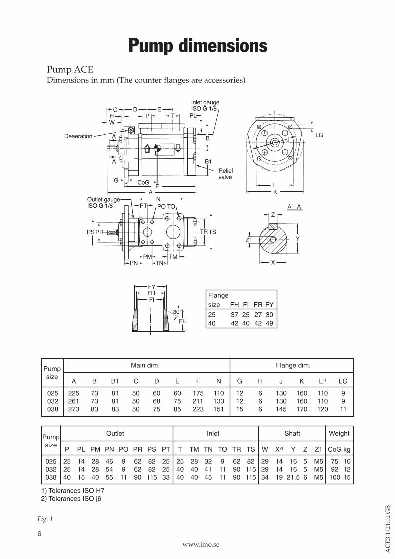
Pump dimensions
Fig. 1
Pump ACEDimensions in mm (The counter flanges are accessories)
Main dim. Flange dim.
A B B1 C D E F N G H J K L1) LG
025 225 73 81 50 60 60 175 110 12 6 130 160 110 9032 261 73 81 50 68 75 211 133 12 6 130 160 110 9038 273 83 83 50 75 85 223 151 15 6 145 170 120 11
Outlet Inlet Shaft Weight
P PL PM PN PO PR PS PT T TM TN TO TR TS W X2) Y Z Z1 CoG kg
025 25 14 28 46 9 62 82 25 25 28 32 9 62 82 29 14 16 5 M5 75 10032 25 14 28 54 9 62 82 25 40 40 41 11 90 115 29 14 16 5 M5 92 12038 40 15 40 55 11 90 115 33 40 40 45 11 90 115 34 19 21,5 6 M5 100 15
1) Tolerances ISO H72) Tolerances ISO j6
Pumpsize
Pumpsize
Flangesize FH FI FR FY
25 37 25 27 3040 42 40 42 49
7
www.imo.se
AC
E3
1121
.02
GB
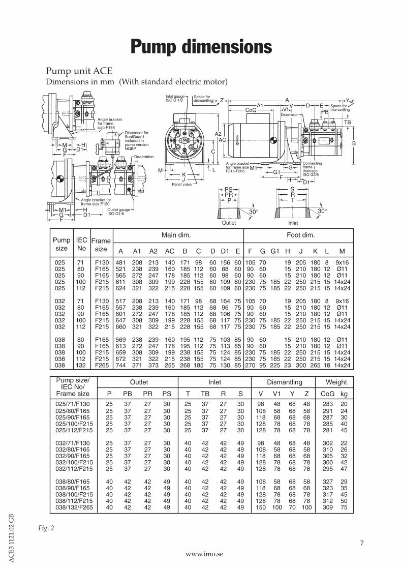
Pump dimensions
Fig. 2
Pump unit ACEDimensions in mm (With standard electric motor)
Main dim. Foot dim.
A A1 A2 AC B C D D1 E F G G1 H J K L M
025 71 F130 481 208 213 140 171 98 60 156 60 105 70 19 205 180 8 9x16025 80 F165 521 238 239 160 185 112 60 88 60 90 60 15 210 180 12 Ø11025 90 F165 565 272 247 178 185 112 60 98 60 90 60 15 210 180 12 Ø11025 100 F215 611 308 309 199 228 155 60 109 60 230 75 185 22 250 215 15 14x24025 112 F215 624 321 322 215 228 155 60 109 60 230 75 185 22 250 215 15 14x24
032 71 F130 517 208 213 140 171 98 68 164 75 105 70 19 205 180 8 9x16032 80 F165 557 238 239 160 185 112 68 96 75 90 60 15 210 180 12 Ø11032 90 F165 601 272 247 178 185 112 68 106 75 90 60 15 210 180 12 Ø11032 100 F215 647 308 309 199 228 155 68 117 75 230 75 185 22 250 215 15 14x24032 112 F215 660 321 322 215 228 155 68 117 75 230 75 185 22 250 215 15 14x24
038 80 F165 569 238 239 160 195 112 75 103 85 90 60 15 210 180 12 Ø11038 90 F165 613 272 247 178 195 112 75 113 85 90 60 15 210 180 12 Ø11038 100 F215 659 308 309 199 238 155 75 124 85 230 75 185 22 250 215 15 14x24038 112 F215 672 321 322 215 238 155 75 124 85 230 75 185 22 250 215 15 14x24038 132 F265 744 371 373 255 268 185 75 130 85 270 95 225 23 300 265 18 14x24
Outlet Inlet Dismantling Weight
P PB PR PS T TB R S V V1 Y Z CoG kg
025/71/F130 25 37 27 30 25 37 27 30 98 48 68 48 283 20025/80/F165 25 37 27 30 25 37 27 30 108 58 68 58 291 24025/90/F165 25 37 27 30 25 37 27 30 118 68 68 68 287 30025/100/F215 25 37 27 30 25 37 27 30 128 78 68 78 285 40025/112/F215 25 37 27 30 25 37 27 30 128 78 68 78 281 45
032/71/F130 25 37 27 30 40 42 42 49 98 48 68 48 302 22032/80/F165 25 37 27 30 40 42 42 49 108 58 68 58 310 26032/90/F165 25 37 27 30 40 42 42 49 118 68 68 68 305 32032/100/F215 25 37 27 30 40 42 42 49 128 78 68 78 300 42032/112/F215 25 37 27 30 40 42 42 49 128 78 68 78 295 47
038/80/F165 40 42 42 49 40 42 42 49 108 58 68 58 327 29038/90/F165 40 42 42 49 40 42 42 49 118 68 68 68 323 35038/100/F215 40 42 42 49 40 42 42 49 128 78 68 78 317 45038/112/F215 40 42 42 49 40 42 42 49 128 78 68 78 312 50038/132/F265 40 42 42 49 40 42 42 49 150 100 70 100 309 75
Pump size/IEC No/
Frame size
Pumpsize
IECNo
Framesize
L
HD1
8
www.imo.se
AC
E3
1121
.02
GB
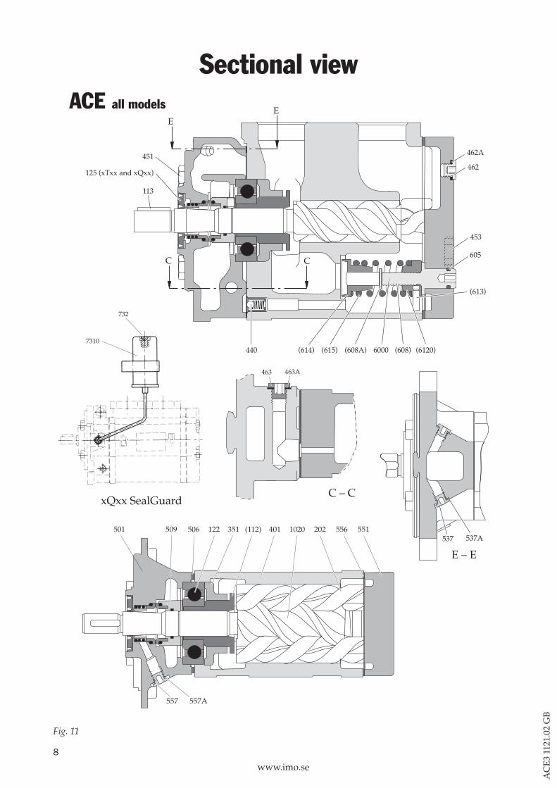
ACE all models
463 463A
C – C
501 509 506 122 351 (112) 401 1020 202 556 551
557 557A
E – E
537A537
xQxx SealGuard
7310
732
Sectional view
Fig. 11
9
www.imo.se
AC
E3
1121
.02
GB
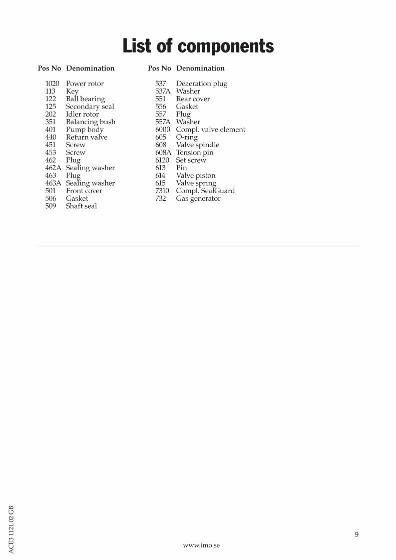
List of componentsPos No Denomination
1020 Power rotor 113 Key 122 Ball bearing 125 Secondary seal 202 Idler rotor 351 Balancing bush 401 Pump body 440 Return valve 451 Screw 453 Screw 462 Plug 462A Sealing washer 463 Plug 463A Sealing washer 501 Front cover 506 Gasket 509 Shaft seal
Pos No Denomination
537 Deaeration plug 537A Washer 551 Rear cover 556 Gasket 557 Plug 557A Washer 6000 Compl. valve element 605 O-ring 608 Valve spindle 608A Tension pin 6120 Set screw 613 Pin 614 Valve piston 615 Valve spring 7310 Compl. SealGuard 732 Gas generator

10
www.imo.se
AC
E3
1121
.02
GB
InstallationThe ACE-pump is designed to be flange-mounted to an electric motor via a connecting frame and a flexible shaft coupling and has an angle bracket for mounting horizontally and vertically, see mounting instructions. Two pump units can also be mounted to a double assembly on a common frame with inlet and outlet pipe connections. The double assembly saves space and facilitates installation, main-tenance, service and supervision. See Product description for T4.
The pump unit, pump with connecting fra-me and motor, is designed to work in an air temperature between +2 °C and +40 °C. This with a maximum humidity of 80 %. For other environmental conditions, please contact your IMO-representative. The pump body, howe-ver, can be heated to maximum fluid tempera-ture.For more information about installation, see the Installation and Service instruction for ACE pumps.
11
www.imo.se
AC
E3
1121
.02
GB
Maintenance and ServiceSpare parts for these pumps are easily available from stock. For detailed information and know-how about service see the Installation and Service instruction for ACE pumps or contact your IMO-representative.
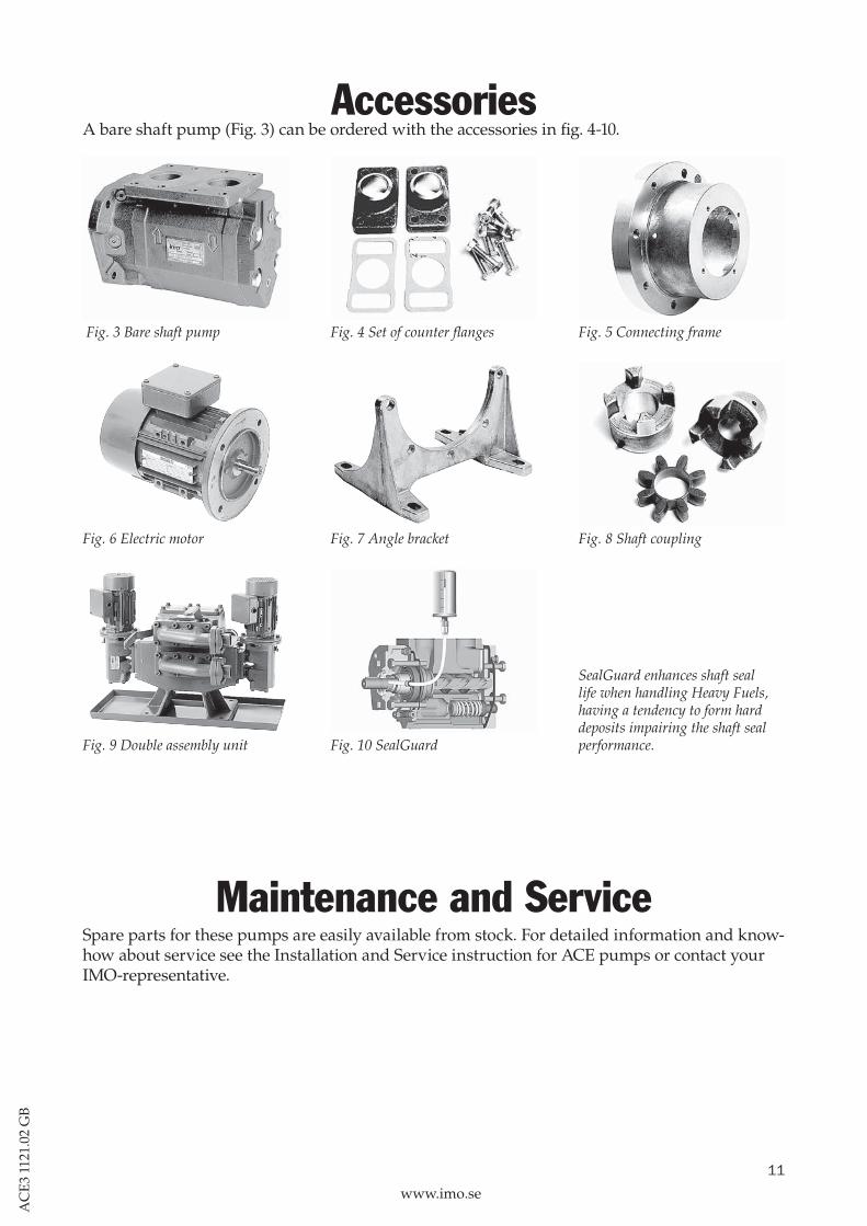
AccessoriesA bare shaft pump (Fig. 3) can be ordered with the accessories in fig. 4-10.
Fig. 3 Bare shaft pump Fig. 4 Set of counter flanges Fig. 5 Connecting frame
Fig. 6 Electric motor Fig. 7 Angle bracket Fig. 8 Shaft coupling
Fig. 9 Double assembly unit Fig. 10 SealGuard
SealGuard enhances shaft seal life when handling Heavy Fuels, having a tendency to form hard deposits impairing the shaft seal performance.

www.imo.se
IMO AB: P. O. Box 42090, SE 126 14 Stockholm, Sweden Telephone: +46 8 50 622 800, Telefax: +46 8 645 1509