
IMO - Sjöfartsverket · Annex 14 LL 65 – Ships with assigned reduced freeboards intended to...
33
I:\MSC\75\19-2.doc For reasons of economy, this document is printed in a limited number. Delegates are kindly asked to bring their copies to meetings and not to request additional copies. INTERNATIONAL MARITIME ORGANIZATION IMO E MARITIME SAFETY COMMITTEE 75th session Agenda item 19 MSC 75/19/2 31 October 2001 Original: ENGLISH RELATIONS WITH OTHER ORGANIZATIONS IACS Unified Interpretations Submitted by IACS SUMMARY Executive summary: This paper advises on a number of IACS Unified Interpretations implemented by IACS Members from 1 January and 1 July 2001, respectively. Action to be taken: Paragraph 4 Related documents: MSC 74/24, paragraphs 19.4 and 19.5 1 Attached as annexes 1 to 15 are IACS Interim Unified Interpretations, which are being applied by IACS Members in accordance with their respective implementation date (see the note at the bottom of each interpretation), as follows: Annex 1 SC 3 – Emergency source of electrical power SC 152 – Use of emergency generator in port (SOLAS regulations II-1/42.1.4 and 43.1.4) Annex 2 SC 10 - Precautions against shock, fire and other hazards of electrical origin (SOLAS regulation II-1/45.5.2) Annex 3 SC 25 – Fixed gas fire-extinguishing systems (SOLAS regulation II-2/5.1.6) Annex 4 SC 30 – Fire-extinguishing arrangements in machinery (SOLAS regulations II-2/7.1 and 7.2) Annex 5 SC 70 – Area classification and selection of electrical equipment (SOLAS regulations II-2/59.1.7 and 59.1.9 [1981]; IBC Code, paragraph 8.3.3.2; IGC Code, paragraph 8.2.10) Annex 6 SC 73 – Fire protection arrangements in cargo spaces including special category spaces (SOLAS regulations II-2/37.1.5.3 and 53.2.2.3 [1981])
Transcript of IMO - Sjöfartsverket · Annex 14 LL 65 – Ships with assigned reduced freeboards intended to...
I:\MSC\75\19-2.doc
For reasons of economy, this document is printed in a limited number. Delegates are kindly asked to bring their copies to meetings and not to request additional copies.
INTERNATIONAL MARITIME ORGANIZATION
IMO
E
MARITIME SAFETY COMMITTEE 75th session Agenda item 19
MSC 75/19/2
31 October 2001 Original: ENGLISH
RELATIONS WITH OTHER ORGANIZATIONS
IACS Unified Interpretations
Submitted by IACS
SUMMARY
Executive summary:
This paper advises on a number of IACS Unified Interpretations implemented by IACS Members from 1 January and 1 July 2001, respectively.
Action to be taken:
Paragraph 4
Related documents:
MSC 74/24, paragraphs 19.4 and 19.5
1 Attached as annexes 1 to 15 are IACS Interim Unified Interpretations, which are being applied by IACS Members in accordance with their respective implementation date (see the note at the bottom of each interpretation), as follows:
Annex 1 SC 3 – Emergency source of electrical power SC 152 – Use of emergency generator in port
(SOLAS regulations II-1/42.1.4 and 43.1.4)
Annex 2 SC 10 - Precautions against shock, fire and other hazards of electrical origin (SOLAS regulation II-1/45.5.2)
Annex 3 SC 25 – Fixed gas fire-extinguishing systems
(SOLAS regulation II-2/5.1.6) Annex 4 SC 30 – Fire-extinguishing arrangements in machinery (SOLAS regulations II-2/7.1 and 7.2) Annex 5 SC 70 – Area classification and selection of electrical equipment
(SOLAS regulations II-2/59.1.7 and 59.1.9 [1981]; IBC Code, paragraph 8.3.3.2; IGC Code, paragraph 8.2.10)
Annex 6 SC 73 – Fire protection arrangements in cargo spaces including special
category spaces (SOLAS regulations II-2/37.1.5.3 and 53.2.2.3 [1981])
MSC 75/19/2 - 2 -
I:\MSC\75\19-2.DOC
Annex 7 SC 126 – Fire protection materials for cargo ships (SOLAS regulations II-2/49.2, 50.2, 50.3.1, 50.3.2 and 50.3.3) Annex 8 SC 155 – Lightweight check in lieu of inclining test (SOLAS regulation II-1/22) Annex 9 SC 157 – Main source of electrical power (SOLAS regulation II-1/41.5) Annex 10 SC 158 – Horizontal fire zone concept (SOLAS regulation II-2/37.1.1.1) Annex 11 SC 159 – Equivalent protection (SOLAS regulations II-2/53.1.2 and 54.2.1 and MSC/Circ.671) Annex 12 SC 160 – Method IIIC construction (SOLAS regulation II-2/52.3) Annex 13 SC 161 – Timber deck cargo in the context of damage stability
requirements (SOLAS regulation II-1/25-8.1) Annex 14 LL 65 – Ships with assigned reduced freeboards intended to carry deck
cargo (LL regulation 27; SOLAS regulation II-1/25-1, footnote 6)
Annex 15 PASSUB 1 – Viewports in passenger submersible craft (IMO Guidelines for the design, construction and operation of passenger
submersible craft (MSC/Circ.981), paragraph 2.2.3)
2 Since these interpretations are considered relevant to port State control inspections, they are brought to the attention of the Committee. 3 The attached interpretations will be applied by IACS members when acting individually as recognized organizations, authorized by flag State Administrations to act on their behalf, until the relevant results of IMO deliberations have been promulgated, thereby superseding these Interim Unified Interpretations. Action requested of the Committee 4 The Committee is invited to note the foregoing and take action as appropriate.
***
ANNEX 1 SC3
IACS Int. 1985/Rev.1 1999
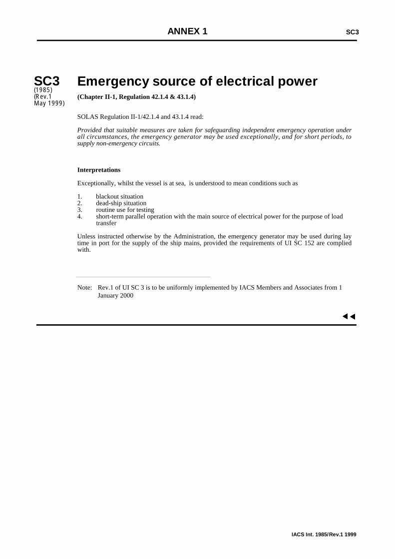
SC3(1985)(Rev.1May 1999)
Emergency source of electrical power(Chapter II-1, Regulation 42.1.4 & 43.1.4)
SOLAS Regulation II-1/42.1.4 and 43.1.4 read:
Provided that suitable measures are taken for safeguarding independent emergency operation underall circumstances, the emergency generator may be used exceptionally, and for short periods, tosupply non-emergency circuits.
Interpretations
Exceptionally, whilst the vessel is at sea, is understood to mean conditions such as
1. blackout situation 2. dead-ship situation3. routine use for testing4. short-term parallel operation with the main source of electrical power for the purpose of load
transfer
Unless instructed otherwise by the Administration, the emergency generator may be used during laytime in port for the supply of the ship mains, provided the requirements of UI SC 152 are compliedwith.
Note: Rev.1 of UI SC 3 is to be uniformly implemented by IACS Members and Associates from 1 January 2000
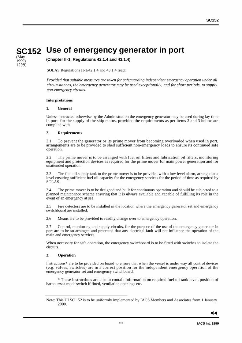
Use of emergency generator in port(Chapter II-1, Regulations 42.1.4 and 43.1.4)
Interpretations
1. General
Unless instructed otherwise by the Administration the emergency generator may be used during lay timein port for the supply of the ship mains, provided the requirements as per items 2 and 3 below arecomplied with.
2. Requirements
2.1 To prevent the generator or its prime mover from becoming overloaded when used in port,arrangements are to be provided to shed sufficient non-emergency loads to ensure its continued safeoperation.
2.2 The prime mover is to be arranged with fuel oil filters and lubrication oil filters, monitoringequipment and protection devices as required for the prime mover for main power generation and forunattended operation.
2.3 The fuel oil supply tank to the prime mover is to be provided with a low level alarm, arranged at alevel ensuring sufficient fuel oil capacity for the emergency services for the period of time as required bySOLAS.
2.4 The prime mover is to be designed and built for continuous operation and should be subjected to aplanned maintenance scheme ensuring that it is always available and capable of fulfilling its role in theevent of an emergency at sea.
2.5 Fire detectors are to be installed in the location where the emergency generator set and emergencyswitchboard are installed.
2.6 Means are to be provided to readily change over to emergency operation.
2.7 Control, monitoring and supply circuits, for the purpose of the use of the emergency generator inport are to be so arranged and protected that any electrical fault will not influence the operation of themain and emergency services.
When necessary for safe operation, the emergency switchboard is to be fitted with switches to isolate thecircuits.
3. Operation
Instructions* are to be provided on board to ensure that when the vessel is under way all control devices(e.g. valves, switches) are in a correct position for the independent emergency operation of theemergency generator set and emergency switchboard.
* These instructions are also to contain information on required fuel oil tank level, position ofharbour/sea mode switch if fitted, ventilation openings etc.
Note: This UI SC 152 is to be uniformly implemented by IACS Members and Associates from 1 January 2000.
SC152
SC152(May1999)1999)
*** IACS Int. 1999
SOLAS Regulations II-1/42.1.4 and 43.1.4 read:
Provided that suitable measures are taken for safeguarding independent emergency operation under allcircumstances, the emergency generator may be used exceptionally, and for short periods, to supplynon-emergency circuits.
▼
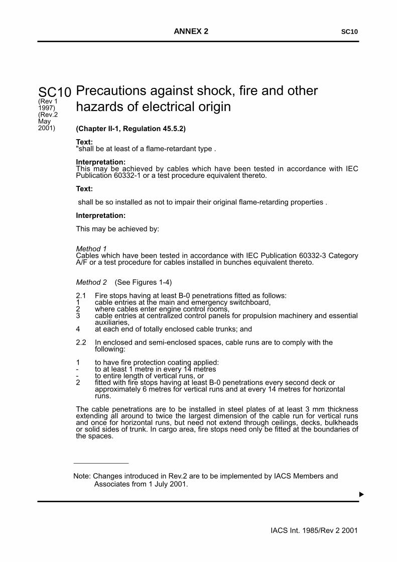
Precautions against shock, fire and otherhazards of electrical origin
(Chapter II-1, Regulation 45.5.2)
Text:"shall be at least of a flame-retardant type .
Interpretation:This may be achieved by cables which have been tested in accordance with IECPublication 60332-1 or a test procedure equivalent thereto.
Text:
shall be so installed as not to impair their original flame-retarding properties .
Interpretation:
This may be achieved by:
Method 1Cables which have been tested in accordance with IEC Publication 60332-3 CategoryA/F or a test procedure for cables installed in bunches equivalent thereto.
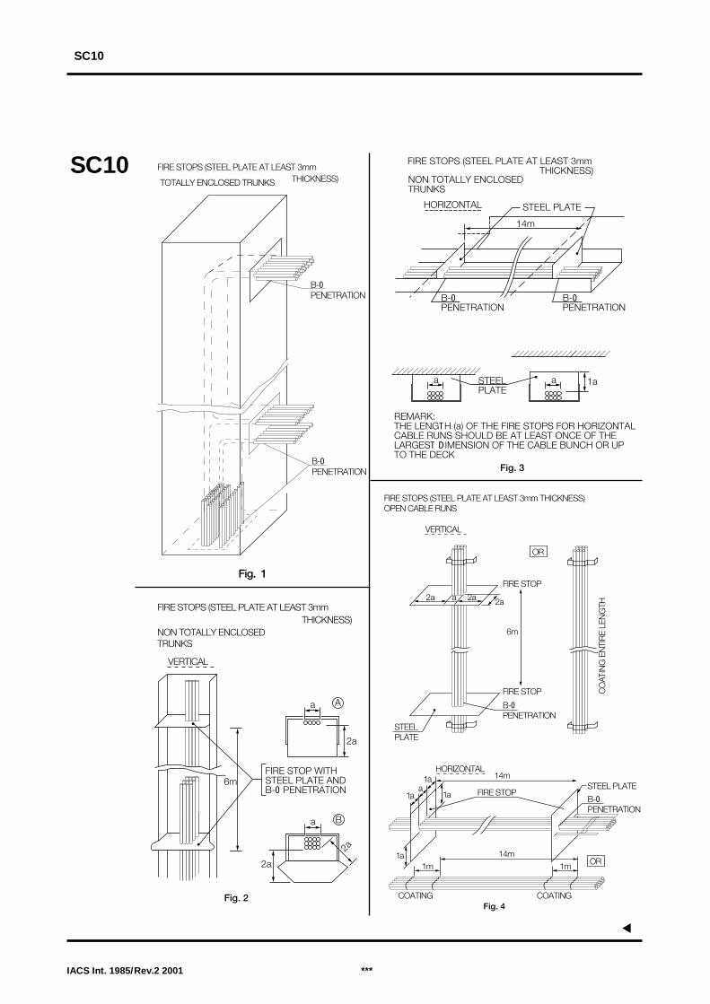
Method 2 (See Figures 1-4)
2.1 Fire stops having at least B-0 penetrations fitted as follows:1 cable entries at the main and emergency switchboard,2 where cables enter engine control rooms,3 cable entries at centralized control panels for propulsion machinery and essential
auxiliaries,4 at each end of totally enclosed cable trunks; and
2.2 In enclosed and semi-enclosed spaces, cable runs are to comply with thefollowing:
1 to have fire protection coating applied:- to at least 1 metre in every 14 metres - to entire length of vertical runs, or2 fitted with fire stops having at least B-0 penetrations every second deck or
approximately 6 metres for vertical runs and at every 14 metres for horizontal runs.
The cable penetrations are to be installed in steel plates of at least 3 mm thicknessextending all around to twice the largest dimension of the cable run for vertical runsand once for horizontal runs, but need not extend through ceilings, decks, bulkheadsor solid sides of trunk. In cargo area, fire stops need only be fitted at the boundaries ofthe spaces.
SC10(Rev 11997)(Rev.2May 2001)
ANNEX 2 SC10
IACS Int. 1985/Rev 2 2001
Note: Changes introduced in Rev.2 are to be implemented by IACS Members andAssociates from 1 July 2001.
IACS Int. 1985/Rev.2 2001 ***
▼
SC10
SC10
FIRE STOPS (STEEL PLATE AT LEAST 3mmTHICKNESS)
NON TOTALLY ENCLOSED TRUNKS
VERTICAL
6mFIRE STOP WITHSTEEL PLATE ANDB-0 PENETRATION
a A
2a
a B
2a
2a
Fig. 2
Fig. 1
B-0PENETRATION
B-0PENETRATION
FIRE STOPS (STEEL PLATE AT LEAST 3mmTHICKNESS)TOTALLY ENCLOSED TRUNKS
B-0PENETRATION
B-0PENETRATION
STEEL PLATE
FIRE STOPS (STEEL PLATE AT LEAST 3mmTHICKNESS)
NON TOTALLY ENCLOSEDTRUNKS
HORIZONTAL
14m
���a STEEL
PLATEa 1a
REMARK:THE LENGTH (a) OF THE FIRE STOPS FOR HORIZONTALCABLE RUNS SHOULD BE AT LEAST ONCE OF THELARGEST DIMENSION OF THE CABLE BUNCH OR UPTO THE DECK
Fig. 3
▼
FIRE STOPS (STEEL PLATE AT LEAST 3mm THICKNESS)OPEN CABLE RUNS
VERTICAL
Fig. 4
FIRE STOP
FIRE STOP
6m
2a a 2a 2a
B-0PENETRATION
STEELPLATE
OR
CO
ATIN
G E
NTI
RE
LEN
GTH
FIRE STOP
HORIZONTAL14m
1 a
1 a
1 a a
14m1m
COATING COATING
1m1 a
B-0PENETRATION
STEEL PLATE
OR
Fixed gas fire-extinguishing systems
(Chapter II-2, Regulation 5.1.6)
Text:"The alarm shall operate for a suitable period before the medium is released".
Interpretation:1) Certain spaces for which the automatic warning of release of the extinguishing medium is
required:Ordinary cargo holds need not comply with Reg. II-2/5.1.6. However, ro/ro cargo spaces, holds incontainer ships equipped for integrated reefer containers and other spaces where personnel can beexpected to enter and where the access is therefore facilitated by doors or manway hatches shall comply with the above regulation.Small spaces, such as small compressor rooms, paint lockers, lamp stores etc. need not complywith Reg. II-2/5.1.6.
2) Advance period of time of alarm sounding:The alarm shall sound for the period of time necessary to evacuate the space but not less than 20 s.
Note: Changes introduced in Rev.1 are to be uniformly implemented by IACS Members and Associates from 1 January 2001.
*** IACS Int. 1985/Rev.1 2000
ANNEX 3 SC25
SC25(1985)(Rev.1 June 2000)
▼▼

IACS Int. 1998/Rev. 1 2000 ***
ANNEX 4 SC30
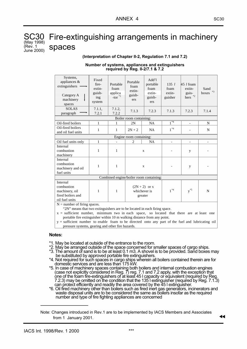
Fire-extinguishing arrangements in machineryspaces
(Interpretation of Chapter II-2, Regulation 7.1 and 7.2)
Number of systems, appliances and extinguishersrequired by Reg. II-2/7.1 & 7.2
Notes:
*1. May be located at outside of the entrance to the room.*2. May be arranged outside of the space concerned for smaller spaces of cargo ships.*3. The amount of sand is to be at least 0.1 m3. A shovel is to be provided. Sand boxes may
be substituted by approved portable fire extinguishers.*4. Not required for such spaces in cargo ships wherein all boilers contained therein are for
domestic services and are less than 175 kW.*5. In case of machinery spaces containing both boilers and internal combustion engines
(case not explicitly considered in Reg. 7) reg. 7.1 and 7.2 apply, with the exception that one of the foam fire-extinguishers of at least 45 l capacity or equivalent (required by Reg. 7.2.3) may be omitted on the condition that the 135 l extinguisher (required by Reg. 7.1.3)can protect efficiently and readily the area covered by the 45 l extinguisher.
*6. Oil fired machinery other than boilers such as fired inert gas generators, incinerators andwaste disposal units are to be considered the same as boilers insofar as the requirednumber and type of fire fighting appliances are concerned
▼
SC30(May 1998)(Rev. 1June 2000)
▼
Systems,appliances &
extinguishers
Category Amachineryspaces
Fixedfire-
extin-guish-
ingsystem
Portable foamapplica
-tor *1
Portablefoamextin-guish-
ers
Add’lportable foamextin-guish-
ers
135 lfoamextin-
guisher
45 l foamextin-guis-hers *2
Sandboxes *3
SOLASparagraph
7.1.1,7.2.1
7.1.2,7.2.2
7.1.3 7.2.3 7.1.3 7.2.3 7.1.4
Boiler room containing:Oil-fired boilers 1 1 2N NA 1*4 - NOil-fired boilersand oil fuel units
1 1 2N + 2 NA 1*4 - N
Engine room containing:Oil fuel units only 1 - 2 NA - - -Internalcombustionmachinery
1 1 x - y -
Internalcombustionmachinery and oilfuel units
1 1 x - y -
Combined engine/boiler room containing:Internalcombustionmachinery, oilfired boilers andoil fuel units
1 1(2N + 2) or xwhichever is
greater1*4 y*5 N
N = number of firing spaces.“2N” means that two extinguishers are to be located in each firing space.
x = sufficient number, minimum two in each space, so located that there are at least oneportable fire extinguisher within 10 m walking distance from any point.
y = sufficient number to enable foam to be directed onto any part of the fuel and lubricating oilpressure systems, gearing and other fire hazards.
Note: Changes introduced in Rev.1 are to be implemented by IACS Members and Associatesfrom 1 January 2001.

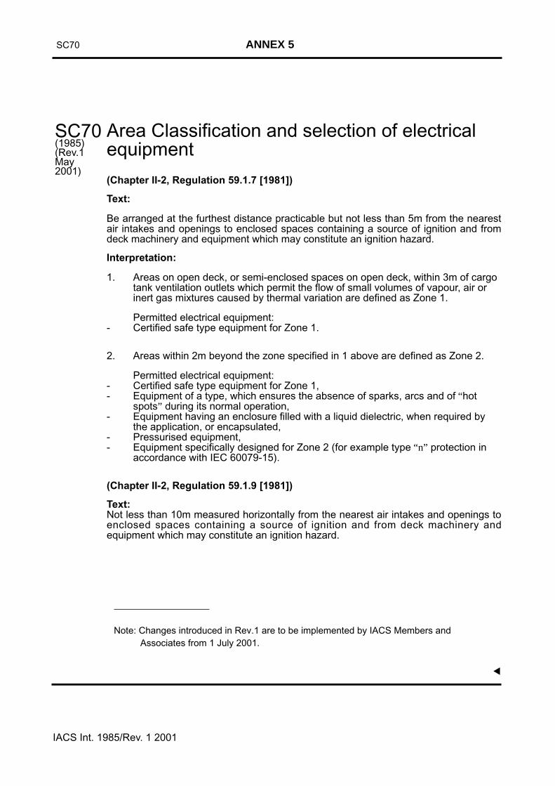
Area Classification and selection of electricalequipment
(Chapter II-2, Regulation 59.1.7 [1981])
Text:
Be arranged at the furthest distance practicable but not less than 5m from the nearestair intakes and openings to enclosed spaces containing a source of ignition and fromdeck machinery and equipment which may constitute an ignition hazard.
Interpretation:
1. Areas on open deck, or semi-enclosed spaces on open deck, within 3m of cargo tank ventilation outlets which permit the flow of small volumes of vapour, air or inert gas mixtures caused by thermal variation are defined as Zone 1.
Permitted electrical equipment:- Certified safe type equipment for Zone 1.
2. Areas within 2m beyond the zone specified in 1 above are defined as Zone 2.
Permitted electrical equipment:- Certified safe type equipment for Zone 1,- Equipment of a type, which ensures the absence of sparks, arcs and of “hot
spots” during its normal operation,- Equipment having an enclosure filled with a liquid dielectric, when required by
the application, or encapsulated,- Pressurised equipment,- Equipment specifically designed for Zone 2 (for example type “n” protection in
accordance with IEC 60079-15).
(Chapter II-2, Regulation 59.1.9 [1981])
Text:Not less than 10m measured horizontally from the nearest air intakes and openings toenclosed spaces containing a source of ignition and from deck machinery andequipment which may constitute an ignition hazard.
SC70(1985)(Rev.1May2001)
IACS Int. 1985/Rev. 1 2001
SC70 ANNEX 5▼
Note: Changes introduced in Rev.1 are to be implemented by IACS Members and Associates from 1 July 2001.
SC 70
SC 70(Cont d)
IACS Int. 1985/Rev.1 2001 ***
▼
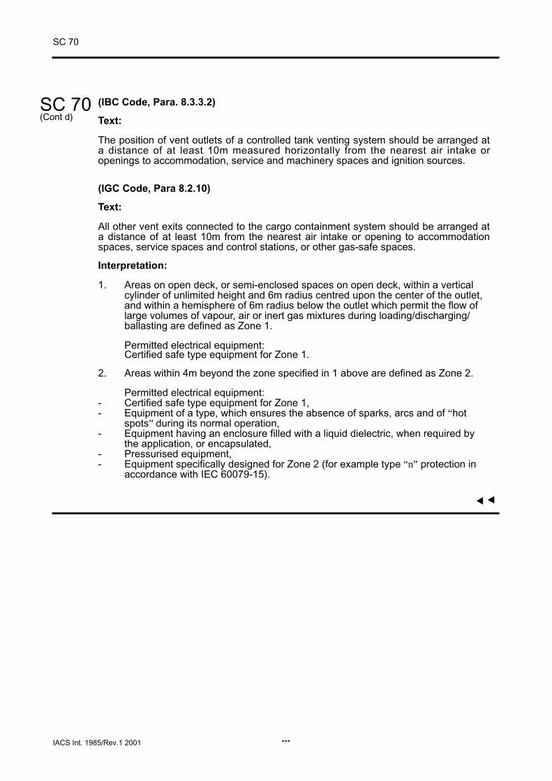
(IBC Code, Para. 8.3.3.2)
Text:
The position of vent outlets of a controlled tank venting system should be arranged ata distance of at least 10m measured horizontally from the nearest air intake oropenings to accommodation, service and machinery spaces and ignition sources.
(IGC Code, Para 8.2.10)
Text:
All other vent exits connected to the cargo containment system should be arranged ata distance of at least 10m from the nearest air intake or opening to accommodationspaces, service spaces and control stations, or other gas-safe spaces.
Interpretation:
1. Areas on open deck, or semi-enclosed spaces on open deck, within a vertical cylinder of unlimited height and 6m radius centred upon the center of the outlet, and within a hemisphere of 6m radius below the outlet which permit the flow of large volumes of vapour, air or inert gas mixtures during loading/discharging/ballasting are defined as Zone 1.
Permitted electrical equipment:Certified safe type equipment for Zone 1.
2. Areas within 4m beyond the zone specified in 1 above are defined as Zone 2.
Permitted electrical equipment:- Certified safe type equipment for Zone 1,- Equipment of a type, which ensures the absence of sparks, arcs and of “hot
spots” during its normal operation,- Equipment having an enclosure filled with a liquid dielectric, when required by
the application, or encapsulated,- Pressurised equipment,- Equipment specifically designed for Zone 2 (for example type “n” protection in
accordance with IEC 60079-15).
▼
Fire protection arrangements in cargo spacesincluding special category spaces
(Chapter II-2, Regulation 37.1.5.3, 53.2.2.3 [1981])
Portable extinguishers suitable for fighting oil fires shall be provided at each car decklevel in each hold of compartment where vehicles are carried, spaced not more than20m apart, on both sides of the ship. One of these extinguishers shall be positioned ateach entrance to the car spaces.
Notes: 1. This need not apply to weather decks used as ro-ro cargo spaces.
2. Changes introduced in Rev.1 are to be implemented by IACS Members andAssociates from 1 July 2001.
SC 73
*** IACS Int. 1985/Rev. 1 2001
▼▼
SC73(1985)(Rev.1May, 2001)
ANNEX 6

▼
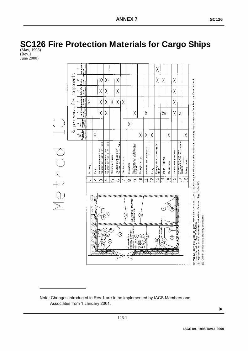
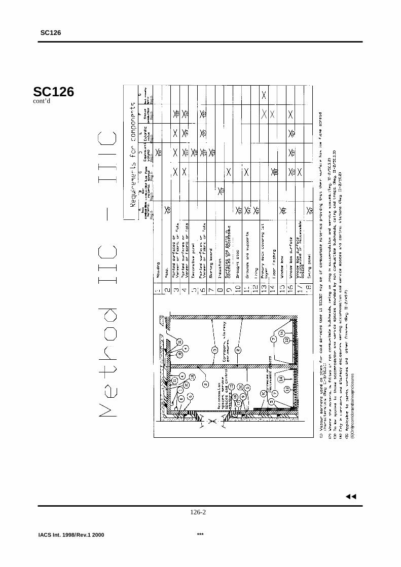
ANNEX 7 SC126
Fire Protection Materials for Cargo Ships
Re
g.I
I-2
/50
.1R
eg
.II-
2/4
9.3
Re
g.I
I-2
/49
.2R
eg.II
-2/5
0.3.
2R
eg.II
-2/5
0.3.
3R
eg
.II-
2/4
9.1
Reg
.II-2
/50.
3.1
14
(3)
(3)
Onl
y in
cor
ridor
s an
d st
airw
ay e
nclo
sure
s
SC126(May, 1998)(Rev.1June 2000)
IACS Int. 1998/Rev.1 2000
Note: Changes introduced in Rev.1 are to be implemented by IACS Members andAssociates from 1 January 2001.
126-1
(4)
Reg
.II-
Reg.
II-R
eg.II
-Re
g.II-
Reg.
II-Re
g.II-
Reg.
II-
14(6
)
(6) O
nly in
corr
idor
s and
stai
rway
encl
osur
es
SC126
SC126cont’d
IACS Int. 1998/Rev.1 2000 ***
▼▼
126-2
ANNEX 8 SC 155
Lightweight check in lieu of inclining test(Regulation II-1/22)
SOLAS regulation Il-1/22.1 requires every new passenger ship regardless of size andevery new cargo ship of 24 m or greater in length to be inclined. Regulation 22.4permits an inclining test to be waived for an individual vessel provided basic stabilitydata is available from the inclining test of a sister vessel and that it can be satisfactorilyshown that such data is valid for the exempted vessel.
1. A sister vessel is a vessel built by the same yard from the same plans.
2. A lightweight check is considered the acceptable means of being satisfied that thedata from a lead sister vessel's inclining test can be used for a subsequent vessel.Members may request regular repeats of inclining tests and /or require each individualpassenger ship to be inclined, if deemed necessary.
3. For any new built sister vessel with known differences from the lead sister vessel orfor a vessel in service which undergoes alterations with calculable differences in lightship properties, a detailed weights and centres calculation, to adjust the lead vessellightship properties or original lightship properties, shall be carried out.
The validity of the calculated lightship properties shall be assessed by carrying out alightweight check unless the implications regarding the stability of the vessel indicatethat an inclining test should be performed.
4. For acceptance of the lightweight check results, the deviation of lightshipdisplacement determined by a light weight check is not to exceed 2% of the expectedvalue, if applicable determined by detailed weights and centres calculation as inparagraph 3 above. In addition, the deviation of lightship longitudinal centre of gravityis not to exceed 1% of LBP of the vessel. Where the deviation exceeds either of theselimits, an inclining test should be carried out.
5. This interpretation is applicable to all vessels for which intact stability is a matter ofclass per UR L2.
Note: This UI SC 155 is to be uniformly implemented by IACS Members andAssociates from 1 January 2001.
SC155(June 2000)
*** IACS Int. 2000
▼▼

ANNEX 9 SC157
Main Source of Electrical Power(Regulation II-1/41.5)
Interpretation of the clause “...will be maintained or immediately restored” as detailedin Reg. II-1/41.5.1.1 amending SOLAS Reg. II-1/41 - Main Source of electrical powerand lighting systems.
1. Reg. II-1/41.5.1.1 - Where the main source of electrical power is necessary forpropulsion and steering of the ship, the system shall be so arranged that the electricalsupply to equipment necessary for propulsion and steering and to ensure safety of theship will be maintained or immediately restored in case of loss of any one of thegenerators in service.
2. To fulfil the above the following measures are required:
2.1 Where the electrical power is normally supplied by more than one generator setsimultaneously in parallel operation, provision of protection, including automaticdisconnection of sufficient non-essential services and if necessary secondary essentialservices and those provided for habitability, should be made to ensure that, in case ofloss of any of these generating sets, the remaining ones are kept in operation to permitpropulsion and steering and to ensure safety.
2.2 Where the electrical power is normally supplied by one generator provision shallbe made, upon loss of power, for automatic starting and connecting to the mainswitchboard of stand-by generator(s) of sufficient capacity with automatic restarting ofthe essential auxiliaries, in sequential operation if required. Starting and connection tothe main switchboard of one generator should be as rapid as possible, preferablywithin 30 seconds after loss of power.Where prime movers with longer starting time are used, this starting and connection
time may be exceeded upon approval from the society.
2.3 Load shedding or other equivalent arrangements should be provided to protectthe generators required by this regulation against sustained overload.
2.3.1 The load shedding should be automatic.
2.3.2 The non-essential services, service for habitable conditions may be shed andwhere necessary, additionally the secondary essential services, sufficient to ensure theconnected generator set(s) is/are not overloaded.
Note: This UI SC 155 is to be uniformly implemented by IACS Members andAssociates from 1 January 2001.
SC157(June 2000)
*** IACS Int. 2000
▼▼

ANNEX 10 SC 158
Horizontal fire zone concept(Reg. II-2/37.1.1.1)
The "Total overall clear height" is the sum of distances between deck and web framesof the decks forming one horizontal zone.
Note: This UI SC 158 is to be uniformly implemented by IACS Members and Associates from 1 January 2001.
*** IACS Int. 2000
▼
SC158(June 2000)
▼

ANNEX 11 SC 159
Equivalent Protection
(Reg. II-2/53.1.2)
Water supplies defined in Reg. II-2/54.2.1.2 are considered as an acceptableprotection for cargoes listed in Table 2 of MSC/Circ. 671.
Note: This UI SC 159 is to be uniformly implemented by IACS Members and Associatesfrom 1 January 2001.
*** IACS Int. 2001
▼
SC159(June 2000)(Corr.1May 2001)
▼

ANNEX 12 SC 160
Method IIIC Construction
(Reg. II-2/52.3)
In the case of ships built in accordance with Method IIIC, the detection system is onlyrelevant to the accommodation block. Service spaces built away from theaccommodation block need not be fitted with a fixed fire detection system.
Note: This UI SC 160 is to be uniformly implemented by IACS Members and Associates from 1 January 2001.
SC160(June 2000)
*** IACS Int. 2000
▼▼

ANNEX 13
Timber deck cargo in the context of damage stability requirements
(Chapter II-1, Regulation 25-8.1)
SOLAS Regulation II-1/25-8.1 reads:
Stability information
1 The master of the ship shall be supplied with such reliable information as isnecessary to enable him by rapid and simple means to obtain accurate guidance as tothe stability of the ship under varying conditions of service. The information shallinclude:
.1 a curve of minimum operational metacentric height (GM) versus draught whichassures compliance with the relevant intact stabil i ty requirements and therequirements of regulations 25-1 to 25-6, alternatively a corresponding curve of themaximum allowable vertical centre of gravity (KG) versus draught, or with theequivalents of either of these curves;
.2 instructions concerning the operation of cross-flooding arrangements; and
.3 all other data and aids which might be necessary to maintain stability afterdamage.
Scope
The provisions given hereunder apply to ships that are subject to SOLAS, Chapter II-1,Part B-1 subdivision and damage stability calculations and engaged in carrying timberdeck cargoes. The buoyancy of the timber deck cargo can optionally be taken intoaccount in the damage stability calculations, subject to the provisions that have beenset forth in this document.
They shall comply with the requirements of the CODE OF SAFE PRACTICE FORSHIPS CARRYING TIMBER DECK CARGOES, 1991, and Ships that are providedwith and make use of their timber load line shall also comply with the requirements ofregulations 41 to 45 of the LOAD LINE CONVENTION, 1966.
Definitions
The following definitions apply for the purposes of this interpretation:
timber means sawn wood or lumber, cants, logs, poles, pulpwood and all other typesof timber in loose or packaged forms. The term does not include wood pulp or similarcargo;
timber deck cargo means a cargo of timber carried on an uncovered part of afreeboard or superstructure deck. The term does not include wood pulp or similarcargo;
timber load line means a special load line assigned to ships complying with certainconditions related to their construction set out in the LOAD LINE CONVENTION 1966and used when the cargo complies with the stowage and securing conditions of theCODE OF SAFE PRACTICE FOR SHIPS CARRYING TIMBER DECK CARGOES,1991 (Resolution A.715(17));
SC161(May 2000)
IACS Int. 2000
Page 2
deepest timber subdivision load line is the subdivision load line which corresponds tothe timber summer draught to be assigned to the ship;
respective partial load line is the light ship draught plus 60% of the difference betweenthe light ship draught and the deepest timber subdivision load line.
Interpretation
1. The stowage of timber deck cargoes shall comply with the provisions of Chapter 3 ofthe CODE OF SAFE PRACTICE FOR SHIPS CARRYING TIMBER DECK CARGOES,1991 (resolution A.715(17)).
2. The ship shall be supplied with comprehensive stability information which takes intoaccount timber deck cargo. Such information shall enable the master, rapidly ands i m p l y, to obtain accurate guidance as to the stability of the ship under varyingconditions of service, and as required in SOLAS Regulation II-1,25-8 it shall include,among other damage stability related issues, a curve of minimum operatingmetacentric height (GM) versus draught which covers the requirements of SOLASRegulation II-1/25-8.1.1.
3. The height and extent of the timber deck cargo shall be in accordance with Chapter3.2 of the CODE OF SAFE PRACTICE FOR SHIPS CARRYING TIMBER DECKCARGOES, 1991, and shall be at least stowed to the standard height of onesuperstructure, if considered buoyant in the context of the subdivision and damagestability calculations.
4. Account may be taken of the buoyancy of the timber deck cargo, assuming thatsuch cargo has a permeability of 25% of the volume occupied by the cargo, however,the buoyancy of only one standard superstructure height of timber deck cargo may beconsidered.
5. Unless instructed otherwise by the Administration, the stability information for shipswith timber deck cargoes may be supplemented by a second curve of limiting GM (orKG) covering the then permissible draught range as specified below. Thus whenaccepting two stability limiting curves one curve shall be applicable when carryingtimber deck cargo and a second curve for any other loading condition.
6. The above described provision of two curves are to be developed as described inSOLAS Regulation II-1/25-8.3, if they have been determined from considerationsrelated to the subdivision index, based on the following:
6.1. for any loading condition other than timber deck cargo the limiting GM with thedraughts as described in SOLAS Regulation II-1/25-8.3, and
6.2. for timber deck cargo
the limiting GM shall be varied linearly between that the deepest timber subdivisionload line and the respective timber partial load line. Where timber freeboards are notassigned the deepest and partial draughts shall relate to the summer load line.
7. For the purpose of the subdivision and damage stability calculations, thepermeabilities of each space or part of space shall be as described in SOLASRegulation II-1/25-7, however supplemented by the following for the undamagedtimber deck cargo:
Spaces Permeability
Timber cargo on deck 0.25
for both draughts.
SC161cont’d
IACS Int. 2000
Page 3
8. When considering the vertical extent of damage, the upper deck may be regardedas a horizontal subdivision (in accordance with SOLAS Regulation II-1/25-6.3). Thuswhen calculating damage cases limited vertically to the upper deck with thecorresponding v-factor, the timber deck cargo may be considered to remain buoyantwith an assumed permeability of 0.25. For damage extending above the upper deckthe timber deck cargo buoyancy in way of the damage zone is to be ignored.
Footnote: Implementation date 1 January 2001
SC161cont’d
*** IACS Int. 2000

Ships wintende
(LLC 66, Re
General:
This UI perta27 of the Intcarry deck ca
In .6 of the fwith ICLL Rmay be exclu
The footnoteline regulatioacceptable sload case mICLL. This cwithin the coccasionally cargo whicassignment.
Therefore for
a) Due torequire
b) Due toby Regcompli
The KG userequiremenprobabilistic the deepest
Note: This Ufrom 1
LL65(June 2000)
ANNEX 14
ith assigned reduced freebd to carry deck cargo
gulation 27 and SOLAS, Chapter II-1, Reg. 25-1
ins to ships assigned reduced freeboards in accernational Convention on Load Lines, 1966 (ILLCrgo.
ootnote to SOLAS Chapter II-1, Regulation 25-1egulation 27 as applied in compliance with IMOded from the application of Part B-1.
accepts the deterministic damage stability analyns in lieu of the probabilistic method of Part B-1.ubstitution because of the very conservative aade in the deterministic calculation under Reguan only be presumed for bulk carriers where thargo holds, but may not always be true for balso carry deck cargo, or other cargo ships inten
h have been designed to take advantage o
such ships damage stability calculations shall be
the assigned reduced freeboards, in compliancments of Regulation 27 ICLL and the 1988 Protoc
the intended deck cargo capacity, the limiting Gulation 25-8 shall be provided to the master
ance with the probabilistic damage stability analys
d for demonstrating compliance with the determts of ICLL Regulation 27 should be the samdamage stability calculations required by SOLAS subdivision load line.
I LL 65 is to be uniformly implemented by IACS M July 2001.
***
LL65
oards
footnote 6)
ordance with Regulation 1966) and intended to
, ships shown to comply Res. A.320 and A.514,
sis according to the load This was considered anssumptions of the initiallation 27(7) of the 1966e cargo is carried solelyulk carriers which mayded for carriage of deckf a reduced freeboard
carried out:
e with damage stabilityol to the ICLL.
M or KG curve requiredfor guidance, based onis of Part B-1.
inistic damage stabilitye as that used for theChapter II-1, Part B-1, at
embers and Associates
IACS INT. 2000
▼▼

ANNEX 15 PASSUB 1
Viewports in Passenger SubmersibleCraft(para. 2.2.3, IMO Guidelines for Design, Construction and Operation of PassengerSubmersible Craft, 2000)
Interpretation
Acrylic viewports are to be designed, fabricated and maintained in accordance with therequirements of the latest edition of the American Society of Mechanical Engineers SafetyStandard for Pressure Vessels for Human Occupancy (ASME PVHO) Section 2 Viewportsand Section 3 Window Fabricators . Other standards and materials may be accepted by theSociety provided they achieve an equivalent level of safety with respect to design, fabricationand maintenance.
Note: Rev.1 of this UI is to be uniformly implemented by IACS Members and Associates from1 January 2001.
IACS Int. 1999/Rev. 1 2000 __________
▼
PASSUB 1(May 1999)(Rev. 1 Aug. 2000)
▼
Paragraph 2.2.3.1 reads:
Viewports should be of acrylic material and in accordance with the requirements of arecognised organisation to the satisfaction of the Administration. Viewports may be of othermaterial, as appropriate, provided viewports of such material are at least as effective and inaccordance with the requirements of a recognised organisation to the satisfaction of theAdministration.
PAS-1