
IMN Installation Manual
136
WALKair V3.1 IMN Installation Manual P/N 110502–00 D REV 1.1 January 2000
-
Upload
ivanliepal -
Category
Documents
-
view
28 -
download
0
description
WALKair 3.1 EN
Transcript of IMN Installation Manual

WALKair V3.1
IMN
Installation Manual
P/N 110502–00 D REV 1.1
January 2000

TABLE OF CONTENTS
P/N 110502–00 REV 1.1 Page i
TABLE OF CONTENTS
IMN Installation Manual...................................................................................... i
1 Introduction ............................................................................................. 1-11.1 Scope ........................................................................................... 1-11.2 Installation Overview .................................................................... 1-11.3 Safety Precautions ....................................................................... 1-21.4 Inventory Check ........................................................................... 1-3
IMN Site Survey Guide ....................................................................................... i
1 Introduction ............................................................................................. 1-11.1 Safety Precautions ....................................................................... 1-11.2 Components Sensitive to Electrostatic Discharge........................ 1-21.3 Additional Safety Requirements ................................................... 1-3
2 General Site Data .................................................................................... 2-12.1 Equipment For Site Survey........................................................... 2-12.2 Site Data ...................................................................................... 2-1
2.2.1 Distance and Azimuth ............................................................. 2-22.2.2 Line of Sight Testing ............................................................... 2-22.2.3 Photos..................................................................................... 2-3
3 Frequency Survey................................................................................... 3-13.1 Equipment for Radio Survey......................................................... 3-13.2 Frequency and Interference Mapping........................................... 3-13.3 Spectrum Images ......................................................................... 3-1
3.3.1 RF Chain................................................................................. 3-23.4 Existing Antennas......................................................................... 3-53.5 Building Climate ........................................................................... 3-73.6 Rack – BU Installation .................................................................. 3-8
3.6.1 Power Supply .......................................................................... 3-83.6.2 Power Distribution Panels ....................................................... 3-83.6.3 Rack Parameters .................................................................... 3-93.6.4 IF Cable .................................................................................3-10
3.7 G.703 2 Mbits/s – Interface to BU (E1)....................................... 3-103.7.1 Projected Equipment ..............................................................3-10
3.8 V.35 / X.21 - Interface to BU ...................................................... 3-113.8.1 Projected Equipment ..............................................................3-11
4 Outdoor Installation................................................................................ 4-14.1 Tower / Mast ................................................................................ 4-14.2 Tower Data................................................................................... 4-2
5 General Comments ................................................................................. 5-1

Chapter 1. Introduction
Page ii P/N 110502–00 REV 1.1
IMN Base Station Installation Guide.................................................................. i
1 Introduction .............................................................................................1-11.1 Safety Precautions........................................................................1-11.2 Components Sensitive to Electrostatic Discharge ........................1-21.3 Additional Safety Requirements....................................................1-41.4 Parts List.......................................................................................1-41.5 Items not Supplied in Part List ......................................................1-5
2 Installation Overview...............................................................................2-1
3 Site Preparation.......................................................................................3-13.1 Rack Preparation ..........................................................................3-1
3.1.1 Pre-installation requirements................................................... 3-13.1.2 Rack Preparation..................................................................... 3-2
3.2 Antenna Mast Installation .............................................................3-23.3 IF Cable Installation ......................................................................3-2
3.3.1 Grounding Cable ..................................................................... 3-33.3.2 Power Distribution Lines.......................................................... 3-3
3.4 IF Cable ........................................................................................3-6
4 Installation for 3.5 GHz ,10.5 GHz and 26 GHz Units ............................4-14.1 BS Installation Overview...............................................................4-14.2 Installing BS Outdoor Equipment..................................................4-2
4.2.1 Mounting the 3.5 GHz and 10.5 GHz Outdoor Unit.................. 4-24.2.2 RFU Cable Connections.......................................................... 4-44.2.3 Antenna Cable Connections.................................................... 4-64.2.4 Mounting the 26 GHz Antenna ................................................ 4-74.2.5 Tools Required........................................................................ 4-74.2.6 Part List................................................................................... 4-7
4.3 BS Indoor Equipment..................................................................4-144.3.1 WALKair - Base Station Site Engineering.............................. 4-144.3.2 IF MUX.................................................................................. 4-184.3.3 BS-BU................................................................................... 4-20
4.4 Cable Connections .....................................................................4-234.4.1 IF MUX Cable Connections ................................................... 4-244.4.2 BU Cable Connections .......................................................... 4-25
5 Initialization..............................................................................................5-15.1 Powering ON ................................................................................5-1
Appendix A Specifications ............................................................................ A-1
Appendix B Base Station Connector Pinouts .............................................. B-1
IMN Terminal Station Installation Guide ........................................................... i
1 Introduction .............................................................................................1-11.1 Safety Precautions........................................................................1-11.2 Components Sensitive to Electrostatic Discharge ........................1-21.3 Additional Safety Requirements....................................................1-31.4 Parts List.......................................................................................1-41.5 Items not Supplied in Part List ......................................................1-4

TABLE OF CONTENTS
P/N 110502–00 REV 1.1 Page iii
2 Site Preparation ...................................................................................... 2-12.1 Housings, Mountings, Dimensions and Clearance....................... 2-12.2 IF Cabling..................................................................................... 2-22.3 Powering and Earthing ................................................................. 2-2
3 Installation............................................................................................... 3-13.1 TS Installation Overview............................................................... 3-13.2 General Tips For RFU-TS Installation .......................................... 3-1
3.2.1 Inspection and Maintenance.................................................... 3-63.3 Mounting the 3.5 GHz or 10.5 GHz TS Antenna .......................... 3-7
3.3.1 3.5 GHz or 10.5 GHz RFU/Antenna ........................................ 3-73.3.2 Installing Mounting Adapter ..................................................... 3-7
3.4 Mounting the 26 GHz TS Dish Antenna ....................................... 3-93.4.1 Optional Mounting Configurations ..........................................3-14
3.5 IF Cable Connections................................................................. 3-153.5.1 RFU/Antenna Cable Connections...........................................3-16
3.6 TS-BU Mounting Bracket Attachment......................................... 3-173.6.1 Wall Mounting ........................................................................3-173.6.2 Desktop Mounting ..................................................................3-193.6.3 Rack Mounting (19" or ETSI racks) ........................................3-203.6.4 TS-BU Cable Connections .....................................................3-21
4 Initialization ............................................................................................. 4-14.1 Powering ON................................................................................ 4-14.2 Commissioning............................................................................. 4-14.3 Operating Temperature and Humidity .......................................... 4-1
Appendix A Terminal Station Connector Pinouts ........................................A-1

P/N 110502–00 REV 1.1 Page 1-1
1 INTRODUCTION
1.1 Scope
This installation manual comprises three main parts:
• Site Survey
• BS Installation Guide
• TS Installation Guide
The BS Installation Guide and TS Installation Guide containscomprehensive step-by-step installation instructions for both the indoorand outdoor components of the WALKair V3.1 system.
1.2 Installation Overview
The typical WALKair V3.1 system installation comprises the following mainitems:
• BS unit installed in either a standard 19" or ESTI rack
• TS unit installed in either a standard 19" or ESTI rack, on desktop orwall mounted
• Antenna and RFU rooftop installation
• Installation of the IF MUX (BS only)
• Cabling requirements
• Local feeding power supply

Chapter 1. Introduction
Page 1-2 P/N 110502–00 REV 1.1
1.3 Safety Precautions
Elevated voltages are present at specific points in this electricalequipment. Some of the parts can also have elevated operatingtemperatures. Non-observance of these conditions and safety instructionscan result in personal injury or in property damage.
The WALKair V3.1 system complies with the standard EN 60950. Allconnected equipment must comply with the applicable safety standards.
Equipment complies with the following EMC and safety standards:
• EN 50081-1
• EN 55022
• IEC 100-4-as 2, 3, 4, 5, 6, 8, 11
• ETSI 300339

WALKair V3.1 IMN Installation Manual
P/N 110502–00 REV 1.1 Page 1-3
1.4 Inventory Check
Before installing the system, ensure that all the equipment that is to beinstalled has arrived. At each site, remove the lists from their envelopes.Take the equipment out of the boxes and check that all parts appearing inthe lists have arrived.
If anything is missing from the order, do not continue with the installationwithout conferring with an experienced installation technician. Make surethat the missing equipment is ordered from the supplier. If you areuncertain whether or not to continue with the installation before themissing equipment arrives, contact the WALKair V3.1 Customer Servicedepartment.

WALKair V3.1
IMN
Site Survey Guide
P/N 110502-01 D REV 1.1
January 2000


TABLE OF CONTENTS
P/N 110502-01 REV 1.1 Page i
TABLE OF CONTENTS
TABLE OF CONTENTS.......................................................................................... i
1 Introduction ............................................................................................. 1-1
2 General Site Data .................................................................................... 2-1
3 Frequency Survey................................................................................... 3-1
4 Outdoor Installation................................................................................ 4-1
5 General Comments ................................................................................. 5-1


P/N 110502-01 REV 1.1 Page 1-1
1 INTRODUCTION
The following document describes the required actions that must beperformed before installing the WALKair V3.1 system.
• Mechanical Requirements
• Environmental conditions
• Electrical Requirements
This information, as well as a site survey, must be obtained prior toinstallation of the BS and the TS. It is recommended that personnel familiarwith the site, for example, the building superintendent, accompany the sitesurveyor. Where multiple BS-BUs are to be installed, copy the relevantsections of this document for the specifications required.
1.1 Safety Precautions
Elevated voltages are present at specific points in this electrical equipment.Some of the parts can also have elevated operating temperatures. Non-observance of these conditions and safety instructions can result in personalinjury or in property damage.
The WALKair V3.1 system complies with the standard EN 60950. Allconnected equipment must comply with the applicable safety standards.
Equipment complies with the following EMC and safety standards:
• EN 50081-1
• EN 55022
• IEC 100-4-as2, 3, 4, 5, 6, 8, 11
• ETSI 300339
Chapter 1. Introduction
Page 1-2 P/N 110502-01 REV 1.1
To avoid injury and prevent equipment damage, observe the following safetyprecautions:
• Do not move or ship equipment unless it is properly packed in its originalwrapping and shipping containers.
• When connecting equipment to the AC and DC voltage supplies, ensurecorrect polarity.
• Equipment service and maintenance should be undertaken only byWALKair V3.1 trained personnel.
• Ground the system units to prevent damage by lightning.
• Do not permit unqualified personnel to operate workstations used tocommunicate with the system.
1.2 Components Sensitive to ElectrostaticDischarge
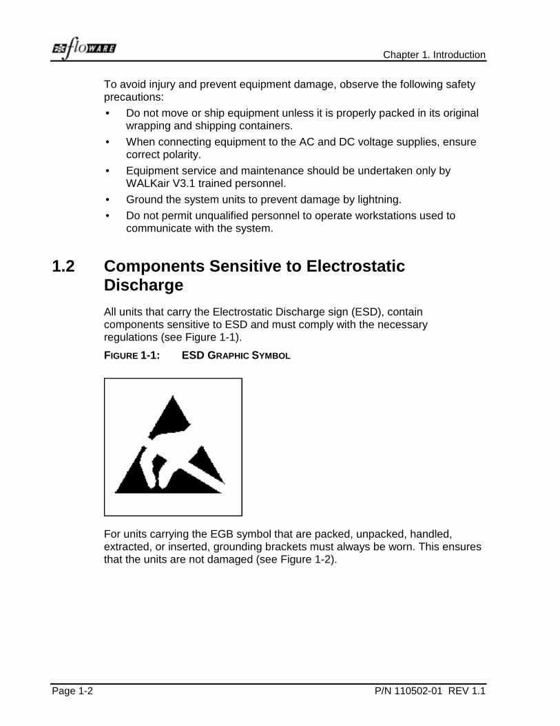
All units that carry the Electrostatic Discharge sign (ESD), containcomponents sensitive to ESD and must comply with the necessaryregulations (see Figure 1-1).
FIGURE 1-1: ESD GRAPHIC SYMBOL
For units carrying the EGB symbol that are packed, unpacked, handled,extracted, or inserted, grounding brackets must always be worn. This ensuresthat the units are not damaged (see Figure 1-2).
WALKair V3.1 IMN Site Survey Guide
P/N 110502-01 REV 1.1 Page 1-3
FIGURE 1-2: EGB GRAPHIC SYMBOL
ESD
• An appropriately labeled grounding socket for the grounding-bracket plugis provided on the right-hand side-securing flange on every subtrack.
• Every PC board has a grounding edge around the outside that isconnected to the “ground” of the plug-in unit by which the board can behandled.
• Contact with the component terminals, the contacts of the SIEDECONconnecting strip and the conductor tracks must be avoided.
• Units located in shielded, closed housings are protected in all cases.European standard EN50082-1 provides information on the properhandling of components that are subject to electrostatic discharge.
1.3 Additional Safety Requirements• When fitting and removing units as part of installation and maintenance
work, the attached insertion and extraction aids must be used.
• DC cable shield must be connected to ground on both sides. Provide asecure connection to the BU case via the D-Type connector.
• Powering off the indoor units is performed by disconnecting the DCpower supply cable.
• When disconnecting the DC power supply cable from the MainDistribution Power, disconnect first the +/- 48V supply and onlyafterwards disconnect the shield.
• E1 output cables should be installed within the same building as theBase Station's BU.

P/N 110502-01 REV 1.1 Page 2-1
2 GENERAL SITE DATA
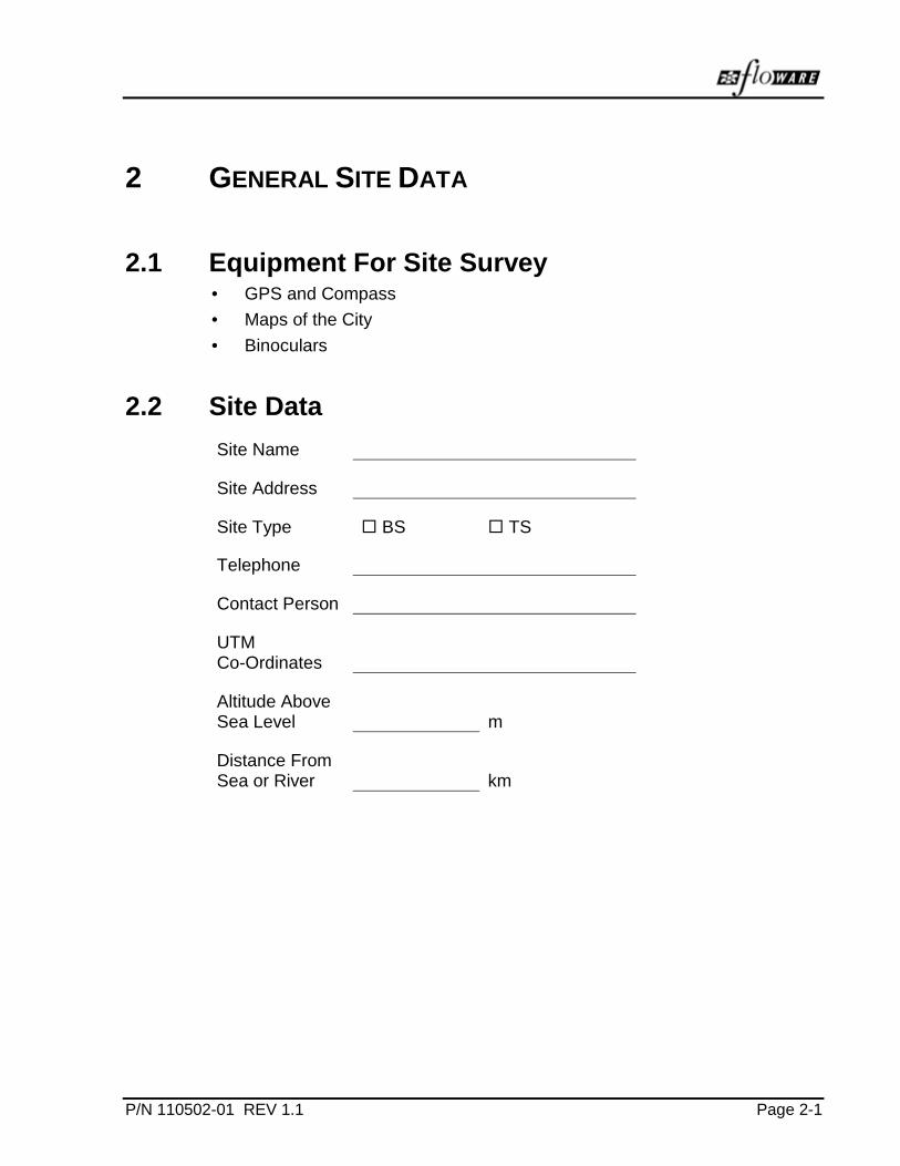
2.1 Equipment For Site Survey• GPS and Compass
• Maps of the City
• Binoculars
2.2 Site Data
Site Name
Site Address
Site Type ! BS ! TS
Telephone
Contact Person
UTMCo-Ordinates
Altitude AboveSea Level m
Distance FromSea or River km
Chapter 2. General Site Data
Page 2-2 P/N 110502-01 REV 1.1
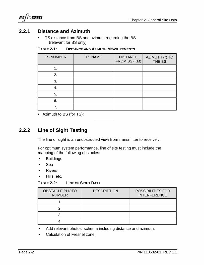
2.2.1 Distance and Azimuth• TS distance from BS and azimuth regarding the BS
(relevant for BS only)
TABLE 2-1: DISTANCE AND AZIMUTH MEASUREMENTS
TS NUMBER TS NAME DISTANCEFROM BS (KM)
AZIMUTH (°) TOTHE BS
1.
2.
3.
4.
5.
6.
7.
• Azimuth to BS (for TS):
2.2.2 Line of Sight Testing
The line of sight is an unobstructed view from transmitter to receiver.
For optimum system performance, line of site testing must include themapping of the following obstacles:
• Buildings
• Sea
• Rivers
• Hills, etc.
TABLE 2-2: LINE OF SIGHT DATA
OBSTACLE PHOTONUMBER
DESCRIPTION POSSIBILITIES FORINTERFERENCE
1.
2.
3.
4.
• Add relevant photos, schema including distance and azimuth.
• Calculation of Fresnel zone.

WALKair V3.1 IMN Site Survey Guide
P/N 110502-01 REV 1.1 Page 2-3
2.2.3 Photos
The surveyor should produce photos that accurately cover the viewing area ofthe proposed site.


P/N 110502-01 REV 1.1 Page 3-1
3 FREQUENCY SURVEY
The Frequency Survey provides a radio data base needed for properoperation of the system.
3.1 Equipment for Radio Survey• Spectrum analyzer
• RF amplifier with power supply
• 60º BS antenna
• RF cable suitable for the frequency band
• Plotter
3.2 Frequency and Interference Mapping
Frequency RangeSelected FrequencyBand
3.5 GHz ! 10.5 GHz ! 26 GHz !
3.3 Spectrum Images
• The polarization of the antenna should be obtained for the verticalposition
• Use the MAX HOLD feature to provide full coverage
• At the BS, a cover area of 360 degrees is required.First capture the proposed operating area of the antenna, and then rotatethe antenna through the required 360 degrees.
• At the TS, a cover area cover of 180 degrees is required.
• Two images are required for every angle. One with a maximum RBW(Resolution Bandwidth) of 2 MHz., and the other with a minimum RBW of1 kHz. The sweep time should be no greater than 50 ms. The VBWshould be in the same position as the RBW.
• The observation span at the BS site will be the uplink band and thedownlink band will be at the TS.
Chapter 3. Frequency Survey
Page 3-2 P/N 110502-01 REV 1.1
• Check for additional interference by changing the polarization of theantenna and the RBW.
• Repeat the above steps with the antenna in the horizontal position.
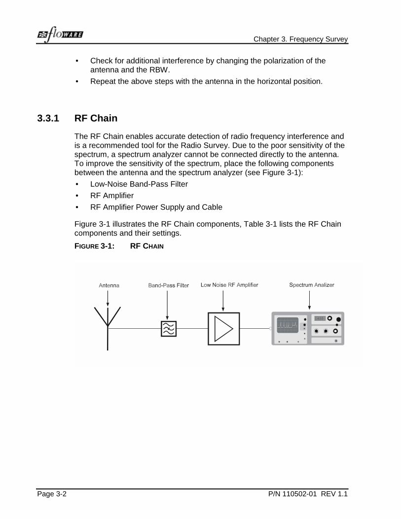
3.3.1 RF Chain
The RF Chain enables accurate detection of radio frequency interference andis a recommended tool for the Radio Survey. Due to the poor sensitivity of thespectrum, a spectrum analyzer cannot be connected directly to the antenna.To improve the sensitivity of the spectrum, place the following componentsbetween the antenna and the spectrum analyzer (see Figure 3-1):
• Low-Noise Band-Pass Filter
• RF Amplifier
• RF Amplifier Power Supply and Cable
Figure 3-1 illustrates the RF Chain components, Table 3-1 lists the RF Chaincomponents and their settings.
FIGURE 3-1: RF CHAIN
1400

WALKair V3.1 IMN Site Survey Guide
P/N 110502-01 REV 1.1 Page 3-3
TABLE 3-1: RF CHAIN COMPONENTS
RF CHAIN COMPONENT CONFIGURATION NOTE
Band-Pass Low NoiseFilter
Prevents RF Amplifier fromgenerating intermodulation
RF Amplifier Set gain to 40-50 dB
Set Noise Figure toMaximum 3 dB
Increases sensitivity of thespectrum analyzer. Frequencyband response should be set tothe appropriate interferenceband. For example, to check forinterference at the 3.5 GHzband, set the Amplifier toreceive a 3-4 GHz frequencyresponse.
The noise level of the spectrumshould increase after supplyingDC to the amplifier.
If the noise level does notincrease:
• Increase the gain setting
• RF Amplifier defective
RF Cable and PowerSupply
Supplies DC voltage to RFAmplifier
Spectrum Analyzer Calibrate before use

Chapter 3. Frequency Survey
Page 3-4 P/N 110502-01 REV 1.1
TABLE 3-2: SPECTRUM IMAGES
SPECTRUMIMAGE
RBW ANGLE RELATIVE TONORTH
ANTENNA BEAMWIDTH
Image 1
Image 2
Image 3
Image 4
Image 5
Image 6
Image 7
Image 8
Image 9
Image 10
Image 11
Image 12
Image 13
Image 14
Image 15
Image 16
Image 17
Image 18
Image 19
Image 20
Image 21
Image 22
Image 23
Image 24
Image 25
WALKair V3.1 IMN Site Survey Guide
P/N 110502-01 REV 1.1 Page 3-5
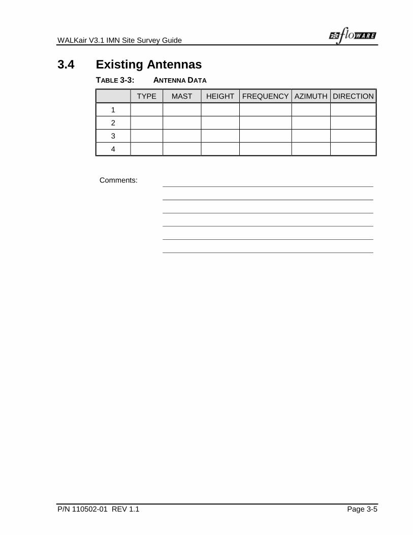
3.4 Existing AntennasTABLE 3-3: ANTENNA DATA
TYPE MAST HEIGHT FREQUENCY AZIMUTH DIRECTION
1
2
3
4
Comments:

Chapter 3. Frequency Survey
Page 3-6 P/N 110502-01 REV 1.1
Draw a top view of the roof (emitters etc., write distances).
FIGURE 3-2: SITE ROOFTOP

WALKair V3.1 IMN Site Survey Guide
P/N 110502-01 REV 1.1 Page 3-7
3.5 Building Climate
Air-conditioning ! Available ! Not Available
Fan ! Available ! Not Available
Comments:

Chapter 3. Frequency Survey
Page 3-8 P/N 110502-01 REV 1.1
3.6 Rack – BU Installation
3.6.1 Power Supply
! DC -48V ! AC 220V Customer !AC 220V Other
AC Distributor(distance fromrack)
m
DC Distributor(distance from rack m
RBC – Earth Bar(distance fromrack)
m
3.6.2 Power Distribution Panels
AC Fuse Panel min. 2A blow(customer supplied)
! Available ! Not Available
DC Fuse Panel min. 5A blow(customer supplied)
! Available ! Not Available
DC Fuse Space forInstallation
! Available ! Not Available
Comments:
WALKair V3.1 IMN Site Survey Guide
P/N 110502-01 REV 1.1 Page 3-9
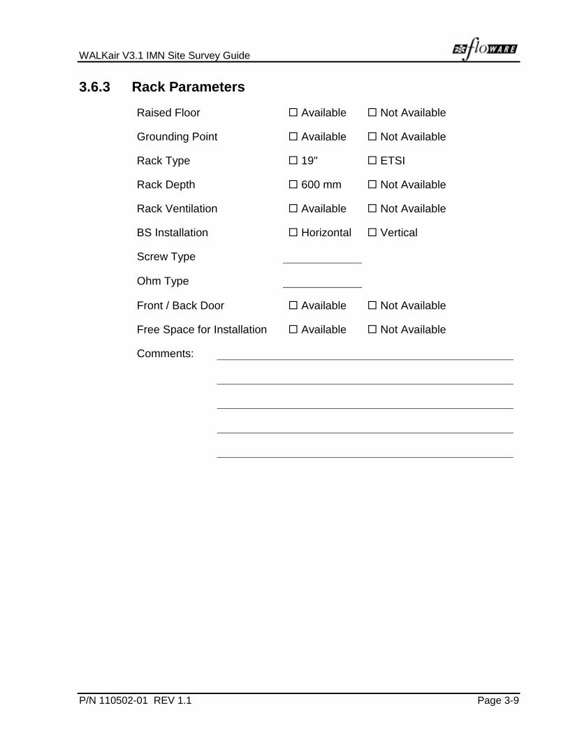
3.6.3 Rack Parameters
Raised Floor ! Available ! Not Available
Grounding Point ! Available ! Not Available
Rack Type ! 19" ! ETSI
Rack Depth ! 600 mm ! Not Available
Rack Ventilation ! Available ! Not Available
BS Installation ! Horizontal ! Vertical
Screw Type
Ohm Type
Front / Back Door ! Available ! Not Available
Free Space for Installation ! Available ! Not Available
Comments:
Chapter 3. Frequency Survey
Page 3-10 P/N 110502-01 REV 1.1
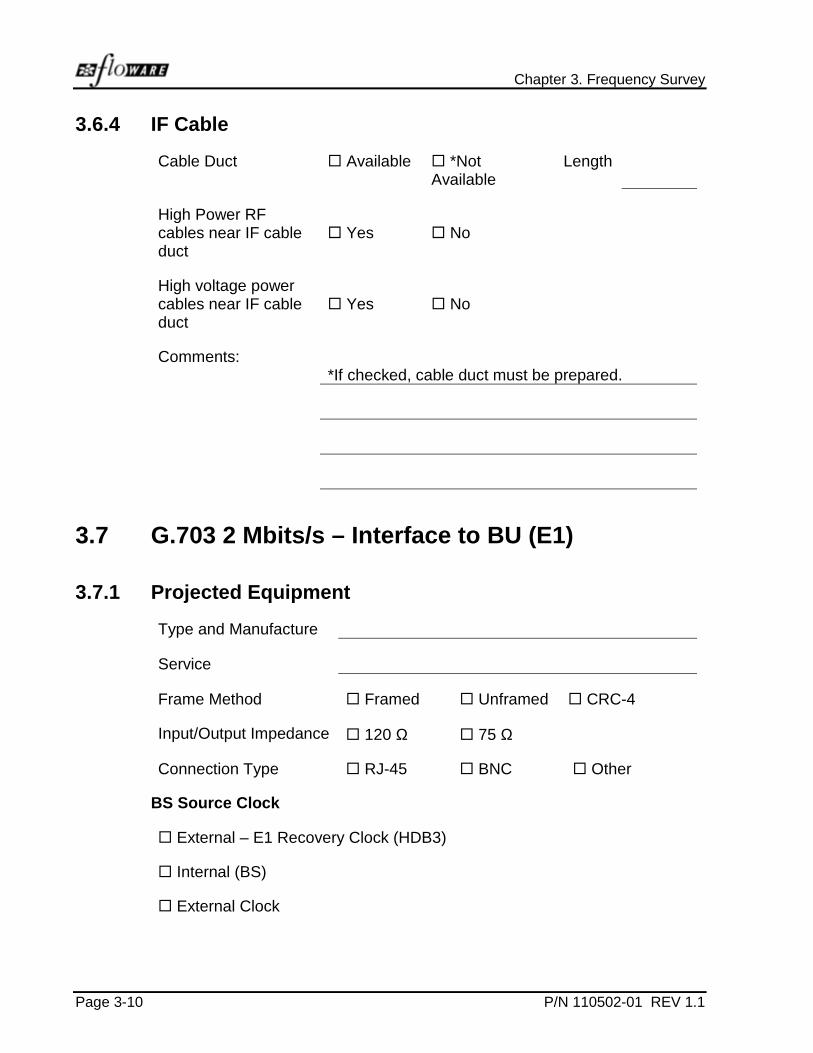
3.6.4 IF Cable
Cable Duct ! Available ! *NotAvailable
Length
High Power RFcables near IF cableduct
! Yes ! No
High voltage powercables near IF cableduct
! Yes ! No
Comments:*If checked, cable duct must be prepared.
3.7 G.703 2 Mbits/s – Interface to BU (E1)
3.7.1 Projected Equipment
Type and Manufacture
Service
Frame Method ! Framed ! Unframed ! CRC-4
Input/Output Impedance ! 120 Ω ! 75 Ω
Connection Type ! RJ-45 ! BNC ! Other
BS Source Clock
! External – E1 Recovery Clock (HDB3)
! Internal (BS)
! External Clock

WALKair V3.1 IMN Site Survey Guide
P/N 110502-01 REV 1.1 Page 3-11
3.8 V.35 / X.21 - Interface to BU
3.8.1 Projected Equipment
Type and Manufacture
Service
Adapter ! V.35
! X.21
Data Rate:
Operating Mode ! DTE
! DCE
Timing Mode ! Internal
! External
Clock Mode ! Standard
! Invert

P/N 110502-01 REV 1.1 Page 4-1
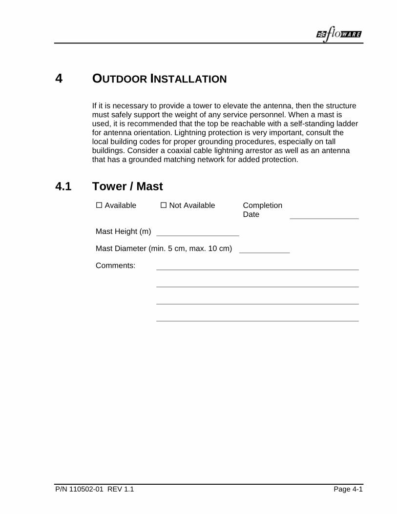
4 OUTDOOR INSTALLATION
If it is necessary to provide a tower to elevate the antenna, then the structuremust safely support the weight of any service personnel. When a mast isused, it is recommended that the top be reachable with a self-standing ladderfor antenna orientation. Lightning protection is very important, consult thelocal building codes for proper grounding procedures, especially on tallbuildings. Consider a coaxial cable lightning arrestor as well as an antennathat has a grounded matching network for added protection.
4.1 Tower / Mast
! Available ! Not Available CompletionDate
Mast Height (m)
Mast Diameter (min. 5 cm, max. 10 cm)
Comments:

Chapter 4. Outdoor Installation
Page 4-2 P/N 110502-01 REV 1.1
4.2 Tower Data
Lightning Protection ! Available ! Not Available
Obstruction Light ! Available ! Not Available
Climbing Ladder ! Available ! Not Available
Protective Earthing ! Available ! Not Available
Extension ! Possible ! Not Possible
Condition ! Very Good ! Good
! Poor ! Very Poor

P/N 110502-01 REV 1.1 Page 5-1
5 GENERAL COMMENTS

WALKair V3.1
IMN
Base Station Installation Guide
P/N 110502-02 D Rev 1.1
January 2000


LIST OF FIGURES
TABLE OF CONTENTS
LIST OF FIGURES................................................................................................ iii
LIST OF TABLES ..................................................................................................iv
1 Introduction ............................................................................................. 1-11.1 Safety Precautions ....................................................................... 1-11.2 Components Sensitive to Electrostatic Discharge........................ 1-21.3 Additional Safety Requirements ................................................... 1-41.4 Parts List ...................................................................................... 1-41.5 Items not Supplied in Part List...................................................... 1-5
2 Installation Overview .............................................................................. 2-1
3 Site Preparation ...................................................................................... 3-13.1 Rack Preparation.......................................................................... 3-1
3.1.1 Pre-installation requirements................................................... 3-13.1.2 Rack Preparation .................................................................... 3-2
3.2 Antenna Mast Installation ............................................................. 3-23.3 IF Cable Installation...................................................................... 3-2
3.3.1 Grounding Cable ..................................................................... 3-33.3.2 Power Distribution Lines.......................................................... 3-3
3.4 IF Cable........................................................................................ 3-6
4 Installation for 3.5 GHz ,10.5 GHz and 26 GHz Units............................ 4-14.1 BS Installation Overview............................................................... 4-14.2 Installing BS Outdoor Equipment ................................................. 4-2
4.2.1 Mounting the 3.5 GHz and 10.5 GHz Outdoor Unit.................. 4-24.2.2 RFU Cable Connections.......................................................... 4-44.2.3 Antenna Cable Connections.................................................... 4-64.2.4 Mounting the 26 GHz Antenna ................................................ 4-74.2.5 Tools Required........................................................................ 4-74.2.6 Part List................................................................................... 4-7
4.3 BS Indoor Equipment ................................................................. 4-144.3.1 WALKair - Base Station Site Engineering...............................4-144.3.2 IF MUX...................................................................................4-18
4.3.2.1 Mounting Bracket Attachments ...........................................4-184.3.2.2 Rack Mounting (19" or ETSI Racks) ...................................4-19
4.3.3 BS-BU....................................................................................4-204.3.3.1 Mounting Bracket Attachments ...........................................4-204.3.3.2 Rack Mount (19" or ETSI Racks) ........................................4-21
4.4 Cable Connections ..................................................................... 4-234.4.1 IF MUX Cable Connections....................................................4-244.4.2 BU Cable Connections ...........................................................4-25
5 Initialization ............................................................................................. 5-15.1 Powering ON................................................................................ 5-1

LIST OF FIGURES.
Appendix A Specifications ............................................................................ A-1
Appendix B Base Station Connector Pinouts .............................................. B-1

LIST OF FIGURES
LIST OF FIGURES
Figure 1-1: ESD Graphic Symbol ............................................................................ 1-2Figure 1-2: EGB Graphic Symbol............................................................................ 1-3Figure 2-1: Installation Overview Block Diagram..................................................... 2-1Figure 3-1: Indoor Equipment Power Connections Rear view ................................. 3-4Figure 3-2: Power Connectors ................................................................................ 3-5Figure 3-3: Polarity Testing ..................................................................................... 3-5Figure 3-4: Connector Short Testing ....................................................................... 3-6Figure 4-1: Base Station Installation - Typical Configuration ................................... 4-2Figure 4-2: Cable Anchoring for 3.5 GHZ Outdoor Unit ........................................... 4-3Figure 4-3: Cable Anchoring for 10.5 GHZ Outdoor Unit ......................................... 4-3Figure 4-4: Connector Interface of the RFU ............................................................ 4-5Figure 4-5: Connector Interfaces of the 3.5 and 10.5 GHz Antennas ...................... 4-6Figure 4-6: 2 racks x 2 sectors x 8 carriers ............................................................4-15Figure 4-7: 8 racks x 8 sectors x 16 carriers ..........................................................4-16Figure 4-8: 4 sectors x 4 carriers............................................................................4-17Figure 4-9: Mounting Bracket Attachment 19" or ETSI racks..................................4-18Figure 4-10: Mounting the IF MUX...........................................................................4-19Figure 4-11: Mounting Bracket Attachment 19" or ETSI Racks ................................4-21Figure 4-12: Mounting the BU’s ...............................................................................4-22Figure 4-13: Mounting Bar Detail .............................................................................4-23Figure 4-14: Front Panel Connector Interface of the IF MUX 8 x SMA Rx/Tx...........4-24Figure 4-15: Front Panel Connector Interface of the IF MUX 16 x sma Rx/Tx..........4-24Figure 4-16: Rear Panel Connector Interface of the IF MUX....................................4-24Figure 4-17: Front Panel Connector Interface of the BU ..........................................4-26Figure 4-18: Rear Panel Connector Interface of the BU...........................................4-26Figure 4-19: Cable Connections Front View Schematic Diagram.............................4-28

LIST OF TABLES.
LIST OF TABLES
Table 1-1: BS Parts List ......................................................................................... 1-4Table 4-1: RFU Cable Inter-Connection................................................................. 4-4Table 4-2: Antenna Cable Inter-connection............................................................ 4-6Table 4-3: Parts List............................................................................................... 4-7Table 4-4: IF MUX Cable Inter-connection ........................................................... 4-25Table 4-5: BU Cable Inter-Connection ................................................................. 4-27Table A-1: Six-Sector Configuration .......................................................................A-1Table A-2: Temperature requirements....................................................................A-1Table B-1: LCI RJ-45 Connector Pinout .................................................................B-1Table B-2: Ethernet Connector Pinout....................................................................B-1Table B-3: External (Office) Clock Connector Pinout ..............................................B-2Table B-4: E1 Rx and Tx Connector Pinout............................................................B-2Table B-5: DB-25 Connector Pin Assignment (DCE Mode) ....................................B-3Table B-6: Cable Adapter for Leased line Card V.35..............................................B-4Table B-7: Cable Adapter for Leased Line Card X.21.............................................B-5
P/N 110502-02 Rev 1.1 Page 1-1
1 INTRODUCTION
The WALKair V3.1 Base Station Installation Guide provides instructions forservice and installation technicians to facilitate installation of theWALKair V3.1 BS and its components. The Site Preparation section of thisguide provides instructions for preparation of the Customer Premises siteprior to installation of the Base Station.
It is assumed that you have a general working knowledge of theWALKair V3.1 system as described in the WALKair V3.1 SystemDescription.
Detailed instructions related to the operation of the WALKair V3.1 systemare available in the WALKair V3.1 Base Station Management Guide.
NOTE
A site survey must be completed prior to the BS installation.(See the Site Survey Guide for details).
1.1 Safety Precautions
High voltages are present at specific points in this electrical equipment.Some of the parts can also have high operating temperatures. Non-observance of these conditions and safety instructions can result inpersonal injury or in property damage.
The WALKair V3.1 system complies with the standard EN 60950. Allconnected equipment must comply with the applicable safety standards.
Equipment complies with the following EMC and safety standards:
• EN 50081-1
• EN 55022
• IEC 100-4-as 2, 3, 4, 5, 6, 8, 11
• ETSI 300339

Chapter 1. Introduction
Page 1-2 P/N 110502-02 Rev 1.1
To avoid injury and prevent equipment damage, observe the followingsafety precautions:
• Do not move or ship equipment unless it is properly packed in itsoriginal wrapping and shipping containers.
• When connecting equipment to the AC and DC voltage supplies,ensure correct polarity.
• Equipment service and maintenance should be undertaken only byWALKair V3.1 trained personnel.
• Ground the system units to prevent damage by lightning.
• Do not permit unqualified personnel to operate workstations used tocommunicate with the system.
1.2 Components Sensitive to ElectrostaticDischarge
All units that carry the Electrostatic Discharge sign (ESD), containcomponents sensitive to ESD and must comply with the necessaryregulations (see Figure 1-1).
FIGURE 1-1: ESD GRAPHIC SYMBOL

WALKair V3.1 IMN Base Station Installation Guide
P/N 110502-02 Rev 1.1 Page 1-3
For units carrying the EGB symbol that are packed, unpacked, handled,extracted, or inserted, grounding brackets must always be worn. Thisensures that the units are not damaged (see Figure 1-2).
FIGURE 1-2: EGB GRAPHIC SYMBOL
ESD
• An appropriately labeled grounding socket for the grounding-bracketplug is provided on the right-hand side-securing flange on everysubtrack.
• Every PC board has a grounding edge around the outside that isconnected to the “ground” of the plug-in unit by which the board can behandled.
• Contact with the component terminals, the contacts of the SIEDECONconnecting strip and the conductor tracks must be avoided.
• Units located in shielded, closed housings are protected in all cases.European standard EN50082-1 provides information on the properhandling of components that are subject to electrostatic discharge.

Chapter 1. Introduction
Page 1-4 P/N 110502-02 Rev 1.1
1.3 Additional Safety Requirements• When fitting and removing units as part of installation and maintenance
work, the attached insertion and extraction aids must be used.
• DC cable shield must be connected to ground on both sides. Provide asecure connection to the BU case via the D-Type connector.
• Powering off the indoor units is performed by disconnecting the DCpower supply cable.
• When disconnecting the DC power supply cable from the MainDistribution Power, disconnect first the +/- 48V supply and onlyafterwards disconnect the shield.
• E1 output cables should be installed within the same building as theBase Station's BU.
1.4 Parts List
The following parts are supplied with the WALKair V3.1 system. In case ofdamage or missing parts, see the WALKair V3.1 System DocumentationForward for related procedures. Table 1-1 contains the BS parts list.
TABLE 1-1: BS PARTS LIST
MAIN EQUIPMENT QUANTITY PER BU
BS-BU 1
IF Cable Jumper 2
IF Multiplexer (as per customer order)
8-port model
16–port model
1
Mounting bars 2
BS RFU 1
RF Cable (as per customer order)
3.5 GHz
10.5 GHz
1
2
Mounting Brackets 2
Bands 2
Mounting Adapter
26 GHz only
1

WALKair V3.1 IMN Base Station Installation Guide
P/N 110502-02 Rev 1.1 Page 1-5
1.5 Items not Supplied in Part List• Electric screwdriver (recommended)
• Coaxial cable between the indoor unit and the outdoor unit
• E1 cables
• LCI cables
• DC power cable for the BS-Bu with 90° connector
• DC power cable for the IF Mux
• Connector sleeves
• IF cable (indoor/outdoor with 90° to the IF Mux(required to close the rack door)
• Rack screws
• Outdoor Strips


P/N 110502-02 Rev 1.1 Page 2-1
2 INSTALLATION OVERVIEW
This installation process for the WALKair V3.1 Base Station and itscomponent devices should proceed in the manner as described in thisdocument. Figure 2-1 shows a block diagram of the installation process.
FIGURE 2-1: INSTALLATION OVERVIEW BLOCK DIAGRAM
Indoor equipment
Outdoor equipment
Verify that power is supplied
Verify that the LEDs are lit
Verify that no fuses jump or burn
Site preparation:
Pre-installation instructions(see para. 3)
Detailed installation instructions
(see para. 4)
Powering ON the equipment
(see para. 5)
Rack preparation
Antenna mast installation
IF cable preparation and testing
Grounding requirements


P/N 110502-02 Rev 1.1 Page 3-1
3 SITE PREPARATION
This section presents a description of the site preparation requirements,prior to installation of the WALKair V3.1 system.
BS installation should proceed in the following order:
1. Rack preparation
2. Antenna mast installation (to be done by the mechanical installer)
3. IF cable installation
4. Grounding infrastructure
3.1 Rack Preparation
3.1.1 Pre-installation requirements
The pre-installation requirements of the rack should be determined asfollows:
• Rack overview
• Placement of the rack based on the proposed BU location
• Preparation of the required screws
• Grounding point location of each rack
• Cable ducting for the following:
! IF cable
! Power cable
! Telecom cables
• Patch panel for rack power or Telecom interface connections asdetermined by Rack equipment planning
• Ventilation
• Power Supply

Chapter 3. Site Preparation
Page 3-2 P/N 110502-02 Rev 1.1
3.1.2 Rack Preparation
Rack preparation includes the following:
• Grounding the rack
• Power distribution line
All WALKair equipment installed in racks, (BS-BU and IF Mux), must begrounded to the rack. Each unit has a grounding pin located on its rearpanel (see Figure 4-16 and Figure 4-18). Connect one end of thegrounding cable to the grounding pin and connect the opposite end of thecable to a central ground point on the rack. The rack must then beconnected to the ground of the room or building.
After grounding, the installer must then verify or test the ground inaccordance with local standards.
3.2 Antenna Mast Installation
The antenna mast must be installed prior to installation of the Base StationBU and RFU. The antenna mast is to be installed by a mechanicalinstaller.
• Verify that the location of the mast is according to the Site Planas specified by the Site Survey Report.
• Verify proper grounding of the mast
• Verify that there is lightning protection prior to installation if the RFU
• Ensure that there is safe access to the mast free of any obstacles orother dangers for installers of the RFU
• Never install the RFU near power lines
3.3 IF Cable Installation
IF Cable installation includes the following:
• Type of cable
• Estimated distance between the outdoor and indoor units
• Cable ducting
• Connector assembly
• Short test prior to connection of equipment

WALKair V3.1 IMN Base Station Installation Guide
P/N 110502-02 Rev 1.1 Page 3-3
3.3.1 Grounding Cable
NOTE
Use accepted methods for grounding (grounding screw, clamp etc.) whenconnecting ground cables
Safety/protective ground is through the rack and the cage connections tothe ground. Ground the rack in the following order:
1. Connect one end of the grounding cable to a central location on therack.
2. Connect the opposite end of the grounding cable to the grounding bolton the cage.
3. Perform a short test on the cable
3.3.2 Power Distribution Lines
Power connections to the BS indoor equipment should be limited to a bustype configuration. An 18-gauge cable is recommended for the -48V-powersupply cable. Each BU requires an individual connection. Figure 3-1illustrates a general view of the BU cable connections.
After installation and connection of the power cable to a power source, apolarity test should be performed on each cable (see Figure 3-3).

Chapter 3. Site Preparation
Page 3-4 P/N 110502-02 Rev 1.1
Step 1:
Deploy the power cable as shown in Figure 3-1.
FIGURE 3-1: INDOOR EQUIPMENT POWER CONNECTIONS REAR VIEW
To Power SupplyTo Power Supply
Power Bus Connections
IF MUX
BS/BU Rear View

WALKair V3.1 IMN Base Station Installation Guide
P/N 110502-02 Rev 1.1 Page 3-5
Step 2:
Assemble the power connectors as per Figure 3-2.
FIGURE 3-2: POWER CONNECTORS
Step 3:
Connect the second side to the power source or power distribution panel.
Step 4:
Power ON the power source.
Step 5:
Test the polarity of the voltage as per Figure 3-3.
FIGURE 3-3: POLARITY TESTING
Reading -48V
NegativeProbe
PositiveProbe
NOTE
Verify prior to testing that the red probe (+) is connected to the red socketon the Test Meter.
Chapter 3. Site Preparation
Page 3-6 P/N 110502-02 Rev 1.1
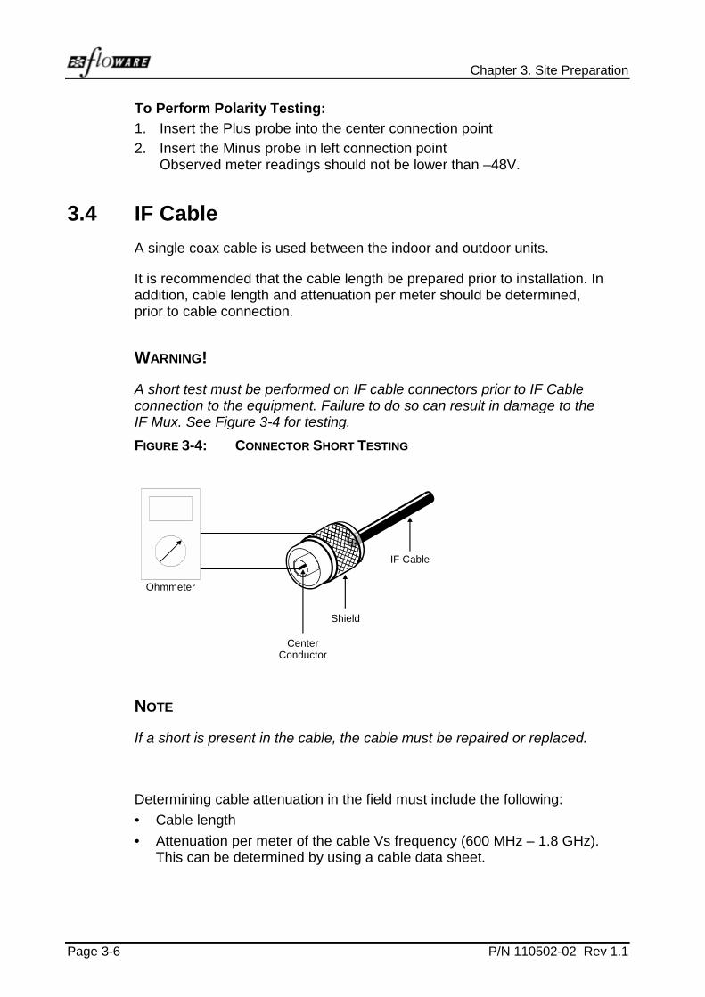
To Perform Polarity Testing:
1. Insert the Plus probe into the center connection point
2. Insert the Minus probe in left connection pointObserved meter readings should not be lower than –48V.
3.4 IF Cable
A single coax cable is used between the indoor and outdoor units.
It is recommended that the cable length be prepared prior to installation. Inaddition, cable length and attenuation per meter should be determined,prior to cable connection.
WARNING!
A short test must be performed on IF cable connectors prior to IF Cableconnection to the equipment. Failure to do so can result in damage to theIF Mux. See Figure 3-4 for testing.
FIGURE 3-4: CONNECTOR SHORT TESTING
Shield
CenterConductor
Ohmmeter
IF Cable
NOTE
If a short is present in the cable, the cable must be repaired or replaced.
Determining cable attenuation in the field must include the following:
• Cable length
• Attenuation per meter of the cable Vs frequency (600 MHz – 1.8 GHz).This can be determined by using a cable data sheet.
P/N 110502-02 Rev 1.1 Page 4-1
4 INSTALLATION FOR 3.5 GHZ ,10.5 GHZ
AND 26 GHZ UNITS
Install the outdoor equipment first, commencing with the RFU. Followingthe installation of the RFU and antenna, prepare all cables (RFU to IFMUX cable, RFU indoor cable connections). Finally, install all the BS-BUs.For easy installation, a power screwdriver is recommended.
NOTE
The location of the RFU on the mast, the location and orientation (azimuth)of the antenna, including tilt when applicable, must be planned anddetermined prior to installation.
4.1 BS Installation Overview
Installation of the BS can proceed after the rack has been prepared asdescribed in para. 3.1. Figure 4-1 illustrates a typical Base StationInstallation.
Installation of the BS includes five main steps:
• Outdoor unit installation
• IF cable installation
• Indoor unit installation
• Power initialization test
Chapter 4. Installation for 3.5 GHz ,10.5 GHzand 26 GHz Units
Page 4-2 P/N 110502-02 Rev 1.1
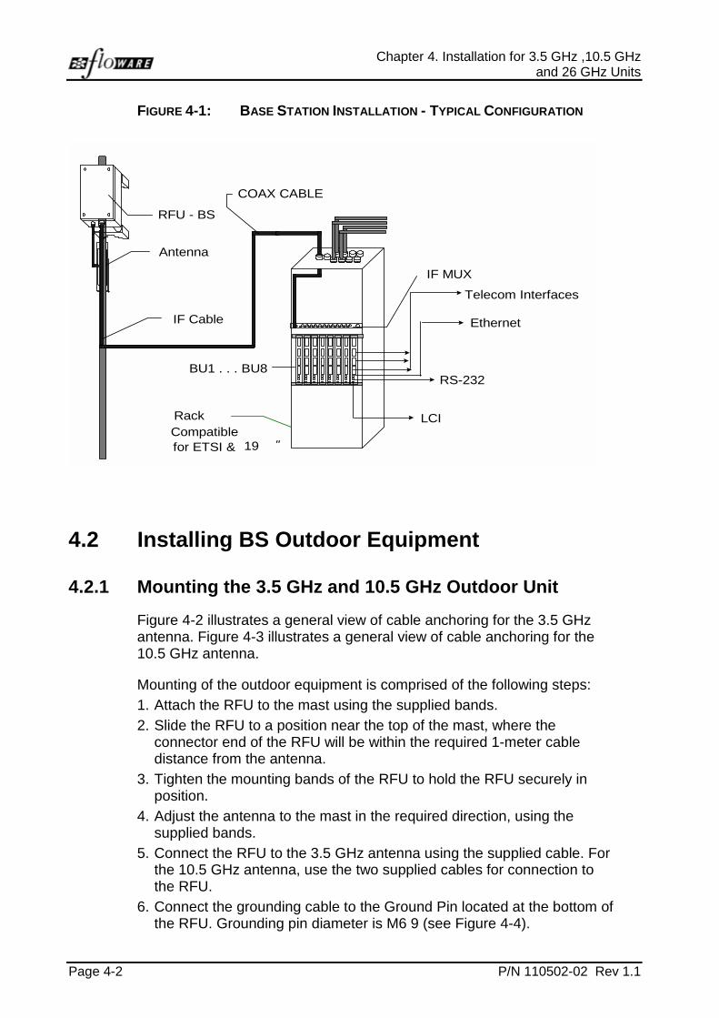
FIGURE 4-1: BASE STATION INSTALLATION - TYPICAL CONFIGURATION
Telecom Interfaces
IF Cable
Antenna
COAX CABLE
LCI
RFU - BS
Ethernet
RS-232BU1 . . . BU8
IF MUX
CompatibleRack
for ETSI & 19 ″
4.2 Installing BS Outdoor Equipment
4.2.1 Mounting the 3.5 GHz and 10.5 GHz Outdoor Unit
Figure 4-2 illustrates a general view of cable anchoring for the 3.5 GHzantenna. Figure 4-3 illustrates a general view of cable anchoring for the10.5 GHz antenna.
Mounting of the outdoor equipment is comprised of the following steps:
1. Attach the RFU to the mast using the supplied bands.
2. Slide the RFU to a position near the top of the mast, where theconnector end of the RFU will be within the required 1-meter cabledistance from the antenna.
3. Tighten the mounting bands of the RFU to hold the RFU securely inposition.
4. Adjust the antenna to the mast in the required direction, using thesupplied bands.
5. Connect the RFU to the 3.5 GHz antenna using the supplied cable. Forthe 10.5 GHz antenna, use the two supplied cables for connection tothe RFU.
6. Connect the grounding cable to the Ground Pin located at the bottom ofthe RFU. Grounding pin diameter is M6 9 (see Figure 4-4).
WALKair V3.1 IMN Base Station Installation Guide
P/N 110502-02 Rev 1.1 Page 4-3
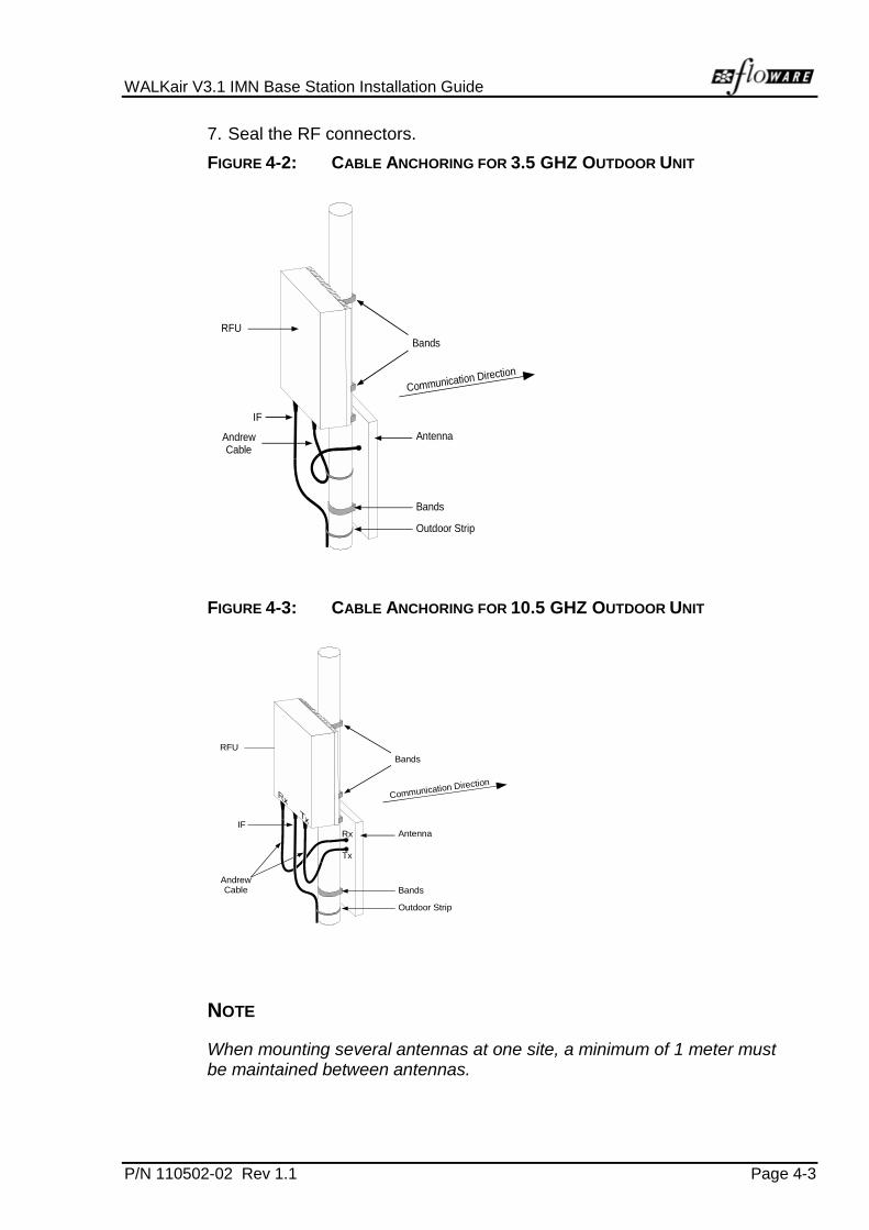
7. Seal the RF connectors.
FIGURE 4-2: CABLE ANCHORING FOR 3.5 GHZ OUTDOOR UNIT
RFU
AndrewCable
Bands
Antenna
Bands
Outdoor Strip
IF
Communication Direction
FIGURE 4-3: CABLE ANCHORING FOR 10.5 GHZ OUTDOOR UNIT
RFU
AndrewCable
Bands
Antenna
Bands
Outdoor Strip
IF
Communication Direction
Rx
Tx
NOTE
When mounting several antennas at one site, a minimum of 1 meter mustbe maintained between antennas.

Chapter 4. Installation for 3.5 GHz ,10.5 GHzand 26 GHz Units
Page 4-4 P/N 110502-02 Rev 1.1
4.2.2 RFU Cable Connections
The RFU has two cable (for 3.5 GHz) connections located at the bottom ofthe RFU, one for 3.5 GHz, between the RFU and Antenna, the secondbetween the RFU and the indoor unit (IF MUX).
The 10.5 GHz has three cable connections, two cable connectionsbetween the RFU and the antenna and a third between the RFU and theIF MUX.
The 26 GHz has only one cable connection between the RFU and the IFMUX.
Prepare and check all cables prior to installation.
Figure 4-4 illustrates a general view of the RFU connector interface.Table 4-1 details the point-to-point cable connections.
TABLE 4-1: RFU CABLE INTER-CONNECTION
CABLE FROM TO CONNECTORS NOTE
COAXLMR400
RFU IF MUX N-Type *Max. Length 150 m
AndrewLDF 3/8
RFU Antenna N-Type Max. Length 1 m
Grounding RFU Ground M6 screw diameter
• For cable lengths greater than 150 m, use a higher quality cable thanthe LMR400. Total cable attenuation must not exceed 20 dB regardlessof cable length.

WALKair V3.1 IMN Base Station Installation Guide
P/N 110502-02 Rev 1.1 Page 4-5
FIGURE 4-4: CONNECTOR INTERFACE OF THE RFU
IFIn/OutAntenna
AntennaTx
10.5 GHz
3.5 GHz
Antenna
26 GHz
IF & DC
IFIn/Out
Grounding
Rx
Grounding
NOTE
• The IF cable connector must be a certified outdoor connector.
• The outdoor connectors should be tightened using sleeves.

Chapter 4. Installation for 3.5 GHz ,10.5 GHzand 26 GHz Units
Page 4-6 P/N 110502-02 Rev 1.1
4.2.3 Antenna Cable Connections
The figures below illustrate a general view of the various connectorinterfaces of the BS antennas: Figure 4-5 illustrates the connectorinterfaces of the 3.5 GHz and 10.5 GHz antennas.
FIGURE 4-5: CONNECTOR INTERFACES OF THE 3.5 AND 10.5 GHZ
ANTENNAS
3.5 GHzAntenna
N-Type
10.5 GHzAntenna
Rx
Tx
Table 4-2 details the cable connection between the RFU and the Antenna.
TABLE 4-2: ANTENNA CABLE INTER-CONNECTION
CABLE FROM TO CONNECTORS NOTE
COAXHeliax Andrew LDF 3/8
RFU Antenna N-Type Max. Length 1m
NOTE
When routing the coaxial cable, leave a service loop at the antenna toprovide a sufficient length of cable to allow replacement of a faultyconnector, when necessary. Secure the coax cable so that there is nomechanical stress at the antenna connection. Follow the super structurewith the cable to its base, and then to the building. If the cable requiressuspension from the base to the building, use a stranded wire to supportthe cable weight. (This support will prevent a migration of the cable's innerconductor to the shield.)

WALKair V3.1 IMN Base Station Installation Guide
P/N 110502-02 Rev 1.1 Page 4-7
4.2.4 Mounting the 26 GHz Antenna
The 26 GHz antenna is mounted on a mast with adjustable mountingbrackets. Mounting of the outdoor equipment is comprised of the followingsteps:
1. Attach the 26 GHz Antenna to the RFU
2. Attach the Elevation Plates to the Brass Plate (used for attaching theRFU/Antenna to the Elevation Plate)
3. Attach the Mounting Brackets to the Elevation Plate
4. Attach the Mounting Bracket to the mast and temporarily adjust forelevation
5. Attach the RFU/Antenna to the Mounting Bracket assembly.
6. Fasten the unit to the mast
7. Adjust the Antenna to the mast in the required direction.
8. Seal the RF connectors
4.2.5 Tools Required• Phillips screw driver
• Flat head screw driver
• Adjustable wrench
4.2.6 Part ListTABLE 4-3: PARTS LIST
PART # QUANTITY
26 GHz Horn antenna 1
Deflectors 2
Mounting brackets 101459-1 2
Aluminum plate 101487-0 1
Aluminum elevation plate 101486-0 Rev A 1
Brass plate 1
ScrewsWashersSpacersLock-washersBolts F593
44444

Chapter 4. Installation for 3.5 GHz ,10.5 GHzand 26 GHz Units
Page 4-8 P/N 110502-02 Rev 1.1
To Mount the Antenna and RFU to the Mast:
1. Remove contents from box.
2. Remove the paper seal from the RFU/Adapter(Not shown).
3. Remove the plastic wave guide dust cover from the back surface of theAntenna.
Wave Guide Dust Cover
4. Install the Antenna onto the RFU/Adapter. Use the Antenna guide pins(2) to align the Antenna onto the RFU/Adapter. Press firmly into place.
5. Fasten the Antenna to the RFU/Adapter with the 8 screws(size 6/32 or 18 mm), washers and lock-washers provided.

WALKair V3.1 IMN Base Station Installation Guide
P/N 110502-02 Rev 1.1 Page 4-9
6. Remove all screws from the Brass Plate
Brass Plate
7. Remove the bolts, washers, and lock-washers from the MountingBracket.
Mounting Brackets
Bolts with WasherLock Washerand Hex Nut
8. Fasten the Elevation Plate to the Brass Plate as shown below.
Chapter 4. Installation for 3.5 GHz ,10.5 GHzand 26 GHz Units
Page 4-10 P/N 110502-02 Rev 1.1
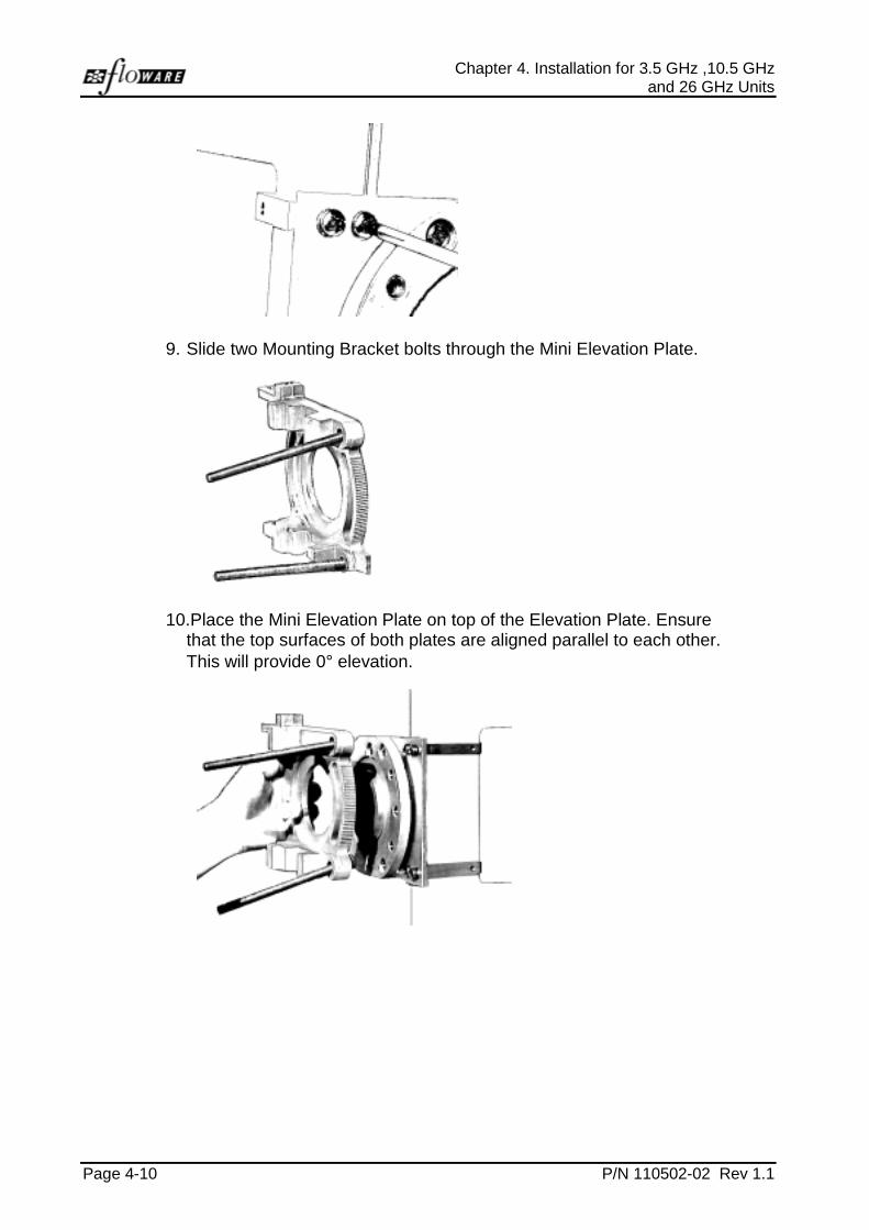
9. Slide two Mounting Bracket bolts through the Mini Elevation Plate.
10. Place the Mini Elevation Plate on top of the Elevation Plate. Ensurethat the top surfaces of both plates are aligned parallel to each other.This will provide 0° elevation.

WALKair V3.1 IMN Base Station Installation Guide
P/N 110502-02 Rev 1.1 Page 4-11
10. Fasten two elevation bolts, spacers, washers and lock-washers in thecenter holes (#2 and #5) of the Mini Elevation Plate.
12
3
45
6
11. Fasten the remaining elevation bolts, spacers, washers andlock-washers using holes #3 and #4, for Right mounting the RFU.Use holes #1 and #6 for Left mounting the RFU
3/8 Boltswith Nylon Spacer
Washer andLock Washer
Chapter 4. Installation for 3.5 GHz ,10.5 GHzand 26 GHz Units
Page 4-12 P/N 110502-02 Rev 1.1
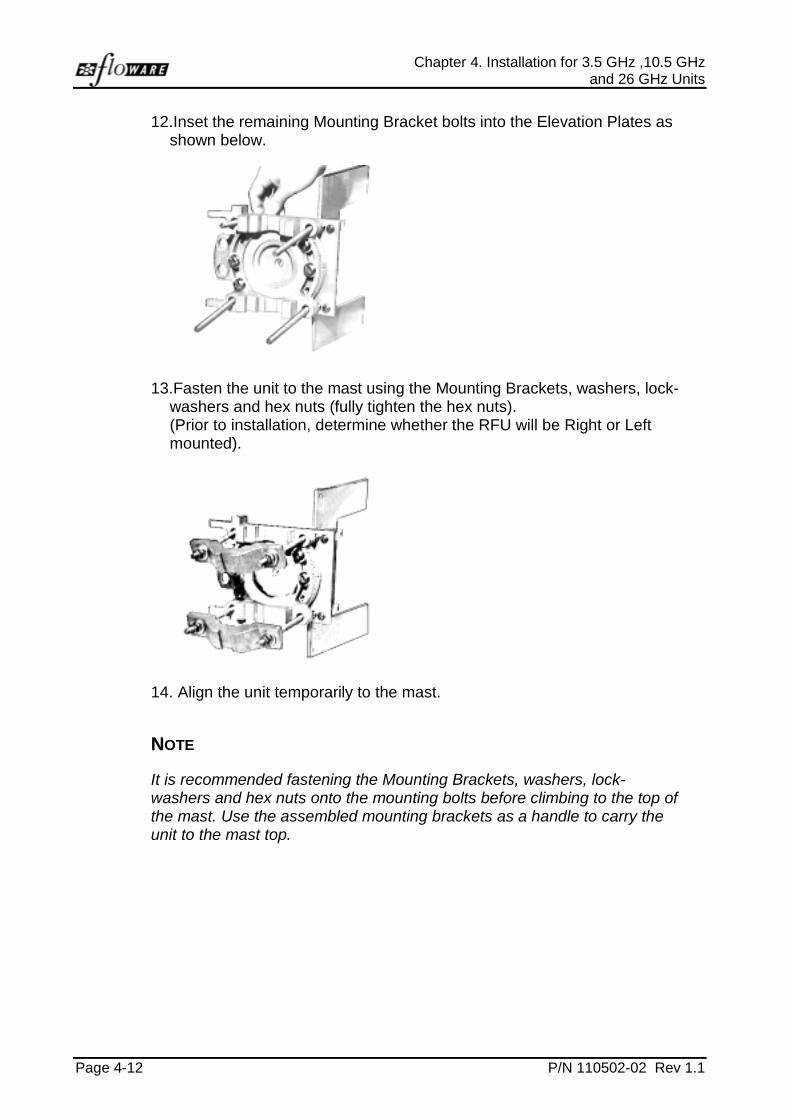
12. Inset the remaining Mounting Bracket bolts into the Elevation Plates asshown below.
13. Fasten the unit to the mast using the Mounting Brackets, washers, lock-washers and hex nuts (fully tighten the hex nuts).(Prior to installation, determine whether the RFU will be Right or Leftmounted).
14. Align the unit temporarily to the mast.
NOTE
It is recommended fastening the Mounting Brackets, washers, lock-washers and hex nuts onto the mounting bolts before climbing to the top ofthe mast. Use the assembled mounting brackets as a handle to carry theunit to the mast top.

WALKair V3.1 IMN Base Station Installation Guide
P/N 110502-02 Rev 1.1 Page 4-13
15. Fasten the RFU/Antenna to the Brass Plate using the 4 screws,washers and lock-washers provided. Align the 4 corner holes of theBrass Plate with the 4 corner holes of the RFU as shown below.
16. Align the Antenna according to the Network Plan.

Chapter 4. Installation for 3.5 GHz ,10.5 GHzand 26 GHz Units
Page 4-14 P/N 110502-02 Rev 1.1
4.3 BS Indoor Equipment
The BS indoor equipment is comprised of the of the following components:
• IF MUX
• BS-BU
• Mounting racks
• Mounting bars
• Cabling
4.3.1 WALKair - Base Station Site Engineering• Different scenarios = different Site engineering
• Scenarios depend on:
! Frequency
! 3.5 GHz (up to 8 carriers per Sector)
! 10.5 GHz (up to 16 carriers per Sector)
! 26 GHz - (up to 16 carriers per Sector)
• Allocated Spectrum - 14 MHz, 28 MHz, 30 MHz
• Number of future sectors in the cell - 4,6,8
• Frequency reuse (dual polarization)
• Additional equipment to consider (per site):
! Ethernet Hub and Router (220V AC)
! Battery backup
! MDF
! Lightning protection
! Additional telecomm equipment (FastLink, ATM Mux, etc.)
• Cables:
! Telecomm
! IF
! Redundancy (between BUs and IF Mux)
! External clock
! Power and Grounding
WALKair V3.1 IMN Base Station Installation Guide
P/N 110502-02 Rev 1.1 Page 4-15
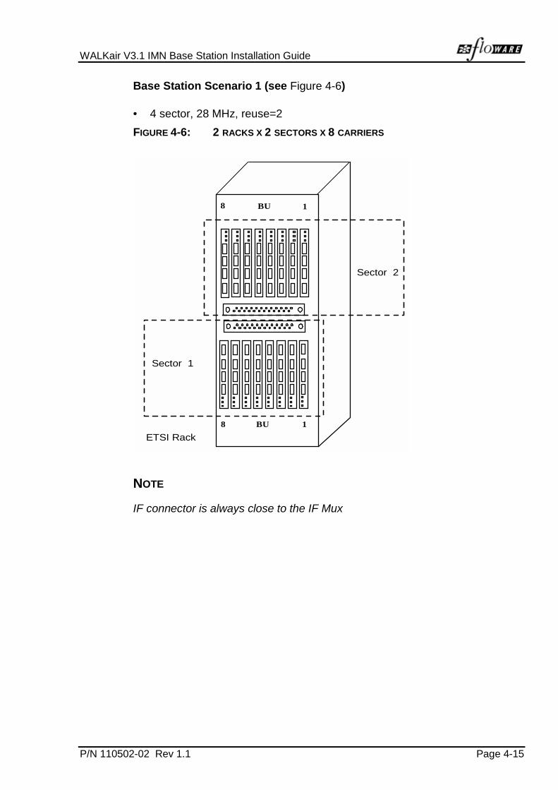
Base Station Scenario 1 (see Figure 4-6)
• 4 sector, 28 MHz, reuse=2
FIGURE 4-6: 2 RACKS X 2 SECTORS X 8 CARRIERS
Sector 1
ETSI Rack
8 BU 1
Sector 2
8 BU 1
NOTE
IF connector is always close to the IF Mux
Chapter 4. Installation for 3.5 GHz ,10.5 GHzand 26 GHz Units
Page 4-16 P/N 110502-02 Rev 1.1
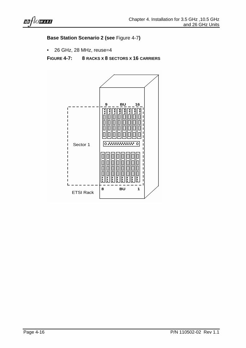
Base Station Scenario 2 (see Figure 4-7)
• 26 GHz, 28 MHz, reuse=4
FIGURE 4-7: 8 RACKS X 8 SECTORS X 16 CARRIERS
ETSI Rack8 BU 1
Sector 1
9 BU 16
WALKair V3.1 IMN Base Station Installation Guide
P/N 110502-02 Rev 1.1 Page 4-17
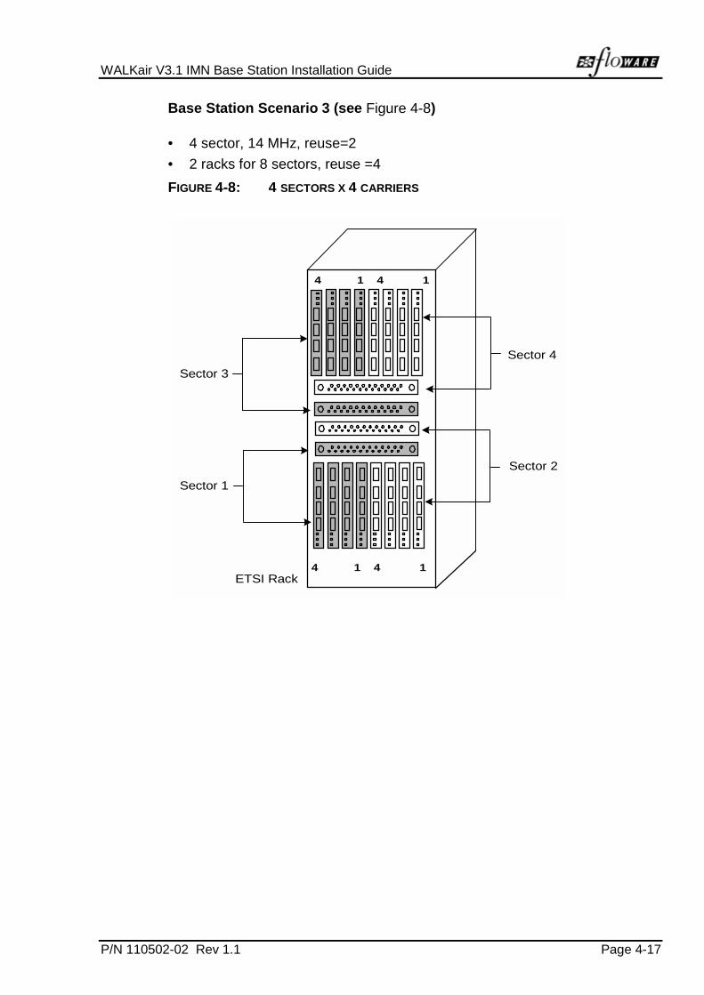
Base Station Scenario 3 (see Figure 4-8)
• 4 sector, 14 MHz, reuse=2
• 2 racks for 8 sectors, reuse =4
FIGURE 4-8: 4 SECTORS X 4 CARRIERS
Sector 2
ETSI Rack4 1 4 1
Sector 3
Sector 4
4 1 4 1
Sector 1

Chapter 4. Installation for 3.5 GHz ,10.5 GHzand 26 GHz Units
Page 4-18 P/N 110502-02 Rev 1.1
4.3.2 IF MUX
4.3.2.1 Mounting Bracket Attachments
Figure 4-9 illustrates the attachment of mounting brackets to the BU forstandard 19" and ETSI racks.
FIGURE 4-9: MOUNTING BRACKET ATTACHMENT 19" OR ETSI RACKS
WALKair V3.1 IMN Base Station Installation Guide
P/N 110502-02 Rev 1.1 Page 4-19
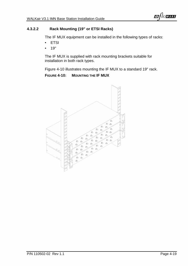
4.3.2.2 Rack Mounting (19" or ETSI Racks)
The IF MUX equipment can be installed in the following types of racks:
• ETSI
• 19"
The IF MUX is supplied with rack mounting brackets suitable forinstallation in both rack types.
Figure 4-10 illustrates mounting the IF MUX to a standard 19″ rack.
FIGURE 4-10: MOUNTING THE IF MUX

Chapter 4. Installation for 3.5 GHz ,10.5 GHzand 26 GHz Units
Page 4-20 P/N 110502-02 Rev 1.1
To Mount the IF MUX:
1. Ground the rack in accordance with the local standards.
2. Insert the IF MUX as shown in Figure 4-10.
3. Fasten the IF MUX mounting brackets to the rack using two screws ateach side.
4. Connect the earth ground to the ground screw of each IF MUX. Theground screw is located on the rear panel of the IF MUX. The groundpin diameter is MC8.
NOTE
It is possible to connect up to three IF MUX units (for three sectors) in asingle rack. Jumper cable length between the IF MUX and the BS-BUlimits connection to no more than three IF MUX units in a single rack,installed with no spacing between them.
4.3.3 BS-BU
The BS-BU interfaces between the Public Switch and the IF MUX of thesystem.
4.3.3.1 Mounting Bracket Attachments
Figure 4-11 illustrates the attachment of mounting brackets to the BU forstandard 19" and ETSI racks.

WALKair V3.1 IMN Base Station Installation Guide
P/N 110502-02 Rev 1.1 Page 4-21
FIGURE 4-11: MOUNTING BRACKET ATTACHMENT 19" OR ETSI RACKS
Mounting Bracket for ETSI Rack
Mounting Bracket forStandard 19 Rack”
4.3.3.2 Rack Mount (19" or ETSI Racks)
The BS indoor equipment can be installed in the following types of racks:
• ETSI
• 19"
The BUs are supplied with rack mounting brackets suitable for installationin both rack types.
The BS indoor equipment (BUs) can be installed in racks, using verticalmounting.

Chapter 4. Installation for 3.5 GHz ,10.5 GHzand 26 GHz Units
Page 4-22 P/N 110502-02 Rev 1.1
FIGURE 4-12: MOUNTING THE BU’S
Cross BarMountingBrackets

WALKair V3.1 IMN Base Station Installation Guide
P/N 110502-02 Rev 1.1 Page 4-23
To mount the BUs (see Figure 4-12):
1. Ground the rack in accordance with the local standards.
2. Fasten the two mounting bars (supplied in the packing) to the rack, at avertical distance of 19 inches apart (see Figure 4-13)
3. Attach mounting brackets to the BS-BUs.
4. Insert the BUs as shown in Figure 4-12 using the two supplied screws(type M-5) at each end to attach the BUs to the mounting brackets.
5. Connect the earth ground to the Ground screw of each BS-BU. TheGround screw is located on the rear panel of the BS-BU. The groundpin diameter is MC8.
FIGURE 4-13: MOUNTING BAR DETAIL
Cable Strip holesScrew holes44cm
(19”)
Cable Strip holesScrew holes
Upper Bar
Lower Bar
Standard 19” or ETSI Rack
NOTE
When mounting BS-BUs in the vertical configuration, you can attach eithertype of mounting brackets (ETSI or 19").
4.4 Cable Connections
Upon entering a building, leave a drip loop so that water will not follow thecable inside. If the cable lays on a roof or the ground, protect it with aconduit to guard against crushing. Inside, at the BS-BU, use a shortflexible patch cable, with the appropriate fittings, from the BS-BU to themain coaxial run for stress elimination at the BU’s SMA connector. Anelectrical short circuit test should be performed on all cable connectionsprior to cable installation. After the test, waterproof all outdoor fittings, theground connections, and the cable entry points into the building.
NOTE
Prepare all cables prior to installation
Chapter 4. Installation for 3.5 GHz ,10.5 GHzand 26 GHz Units
Page 4-24 P/N 110502-02 Rev 1.1
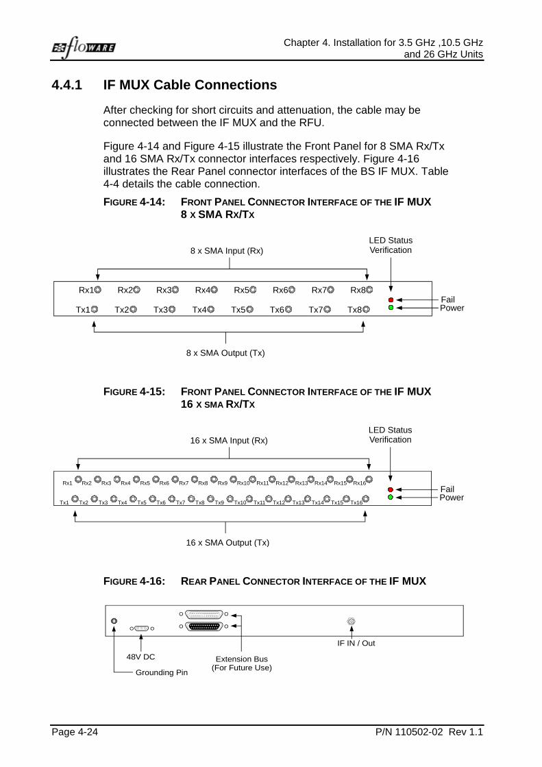
4.4.1 IF MUX Cable Connections
After checking for short circuits and attenuation, the cable may beconnected between the IF MUX and the RFU.
Figure 4-14 and Figure 4-15 illustrate the Front Panel for 8 SMA Rx/Txand 16 SMA Rx/Tx connector interfaces respectively. Figure 4-16illustrates the Rear Panel connector interfaces of the BS IF MUX. Table4-4 details the cable connection.
FIGURE 4-14: FRONT PANEL CONNECTOR INTERFACE OF THE IF MUX8 X SMA RX/TX
8 x SMA Input (Rx)LED StatusVerification
8 x SMA Output (Tx)
Rx1 Rx2 Rx3 Rx4 Rx5 Rx6 Rx7 Rx8
Tx1 Tx2 Tx3 Tx4 Tx5 Tx6 Tx7 Tx8FailPower
FIGURE 4-15: FRONT PANEL CONNECTOR INTERFACE OF THE IF MUX16 X SMA RX/TX
16 x SMA Input (Rx)LED StatusVerification
16 x SMA Output (Tx)
FailPower
Rx2 Rx4 Rx6 Rx8 Rx10 Rx12 Rx14 Rx16
Tx2 Tx4 Tx6 Tx8 Tx10 Tx12 Tx14 Tx16
Rx1 Rx3 Rx5 Rx7 Rx9 Rx11 Rx13 Rx15
Tx1 Tx3 Tx5 Tx7 Tx9 Tx11 Tx13 Tx15
FIGURE 4-16: REAR PANEL CONNECTOR INTERFACE OF THE IF MUX
Extension Bus(For Future Use)
48V DC
Grounding Pin
IF IN / Out

WALKair V3.1 IMN Base Station Installation Guide
P/N 110502-02 Rev 1.1 Page 4-25
TABLE 4-4: IF MUX CABLE INTER-CONNECTION
INTERFACE
APPLICATION FROM TO CONNECTORS NOTE
Front IF IF-MUX BU SMA 8 Input Ports,8 Output Ports
Rear Power IF-MUX -48V DCSupply
3 Pin D-Type
48V and IF IF-MUX RFU N-Type 2 x connectors:
• Main
• Redundancy(for futureuse)
Extension Bus 1 IF-MUX BU 25 Pin D-Type Future ManagementUse
Extension Bus 2 IF-MUX BU 25 Pin D-Type Future ManagementUse
NOTE
• DC cables must be shielded cables up to 3 meters long• DC cables must be connected to ground on both sides• IF cable installation should be performed only by trained personnel
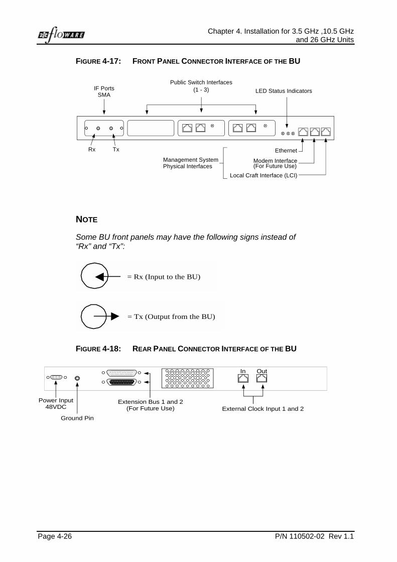
4.4.2 BU Cable Connections
Figure 4-17 and Figure 4-18 illustrates the Front and Rear Panelconnector interfaces of the BU. Figure 4-19 illustrates a general schematicdiagram of the front cabling connections. Table 4-5 details the point-to-point cable connections.
Chapter 4. Installation for 3.5 GHz ,10.5 GHzand 26 GHz Units
Page 4-26 P/N 110502-02 Rev 1.1
FIGURE 4-17: FRONT PANEL CONNECTOR INTERFACE OF THE BU
Local Craft Interface (LCI)
Modem Interface(For Future Use)
Ethernet
LED Status Indicators
Management SystemPhysical Interfaces
Public Switch Interfaces(1 - 3)IF Ports
SMA
Rx Tx
NOTE
Some BU front panels may have the following signs instead of“Rx” and “Tx”:
= Rx (Input to the BU)
= Tx (Output from the BU)
FIGURE 4-18: REAR PANEL CONNECTOR INTERFACE OF THE BU
Extension Bus 1 and 2(For Future Use) External Clock Input 1 and 2
Ground Pin
Power Input48VDC
OutIn

WALKair V3.1 IMN Base Station Installation Guide
P/N 110502-02 Rev 1.1 Page 4-27
TABLE 4-5: BU CABLE INTER-CONNECTION
INTERFACE
APPLICATION FROM TO CONNECTORS NOTE
Front Local CraftInterface
BU Local CraftTerminal
RJ-45 RS-232
ModemInterface
BU Modem/PAD
RJ-45 Future managementuse
Ethernet 802.3 BU 10BaseTEthernet
RJ-45
E1 TelecomInterface
BU SwitchInterface
RJ-45 Max. 2 Mbit/sE1 output cablesshould be installedwithin the samebuilding as the BS-BUs
V.35/X.21TelecomInterface
BU SwitchRouter
Interface
Female DB-25 Max. 2 Mbit/sBoth the V.35 and theX.21 configurations aresupported on the samemechanical connector.Pin assignment as inEIA/TIA –530-A
IF Ports BUs IF-MUX SMA
Rear Power BU -48V DCSupply
3 Pin D-Type
Grounding(earth leakage)
BU RackChassis
Jack Pin
Extension Bus1 IN
BU BU Male DB-25 *For future use
Extension Bus2 OUT
BU BU Female DB-25 *For future use
System ClockIN
ExternalDevice
BU RJ-45
System ClockOUT
BU ExternalDevice
RJ-45

Chapter 4. Installation for 3.5 GHz ,10.5 GHzand 26 GHz Units
Page 4-28 P/N 110502-02 Rev 1.1
FIGURE 4-19: CABLE CONNECTIONS FRONT VIEW SCHEMATIC DIAGRAM
Cable DuctBS/BUFront View
IF MUX
IF Cable
Telecom Interface
48V IF to RFU
Tx
Rx
Tx
Rx

P/N 110502-02 Rev 1.1 Page 5-1
5 INITIALIZATION
5.1 Powering ON
The BS is powered by a standard -48V DC source. As described in theBase Station Site Preparation Guide, the power distribution panel isolationswitch powers on the BS-BUs.
After powering ON the unit ensure that the LED at the IF Mux and thestatus LED’s at the BU’s are lit.
NOTE
The DC power cable must be up to 3-meters long, shielded and have awire gauge of 18 gauge. Provide a secure connection to the BU via theD-Type connector.


P/N 110502-02 Rev 1.1 Page A-1
Appendix A SPECIFICATIONS
TABLE A-1: SIX-SECTOR CONFIGURATION
ITEM SPECIFICATION
Input voltage -48V DC
Power consumption per BS-BU 0.5A
Power consumption per rack: BS RFU: 80W
IF MUX: 24W
BS-BU: 40W
Dimensions: Height = 44 cm (BS-BU) + 2 x 4.7 cm(mounting bars) + 4.4 cm space +4.4 cm (IF MUX)
Total = 62.8 cm
Weight: IF MUX: 1.5 kg
BS-BU: 3 kg
2 x 0.84 kg (mounting bars) = 1.68 kg
Operating Temperature and Humidity
TABLE A-2: TEMPERATURE REQUIREMENTS
ENVIRONMENTAL TEMPERATURE RANGE CONDITIONS
BS Indoor Device(BU)
-5°C to +55°C Is subject to normal indoortemperature and humidityconditions, complies withETS 300019, class 3.2Estandard
BS Outdoor Device -45°C to +55°C Is subject to standard Europeanoutdoor conditions, andcomplies with ETS 300019,class 4.1E. The sealing outdoordevice complies with IP-65standard

P/N 110502-02 Rev 1.1 Page B-1
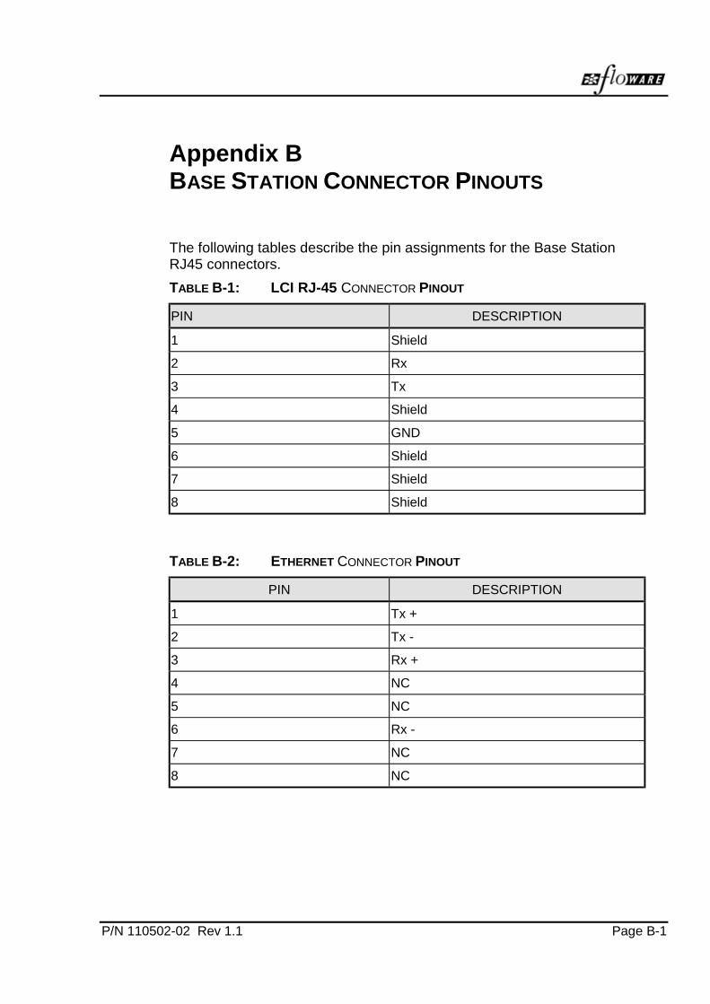
Appendix B BASE STATION CONNECTOR PINOUTS
The following tables describe the pin assignments for the Base StationRJ45 connectors.
TABLE B-1: LCI RJ-45 CONNECTOR PINOUT
PIN DESCRIPTION
1 Shield
2 Rx
3 Tx
4 Shield
5 GND
6 Shield
7 Shield
8 Shield
TABLE B-2: ETHERNET CONNECTOR PINOUT
PIN DESCRIPTION
1 Tx +
2 Tx -
3 Rx +
4 NC
5 NC
6 Rx -
7 NC
8 NC

Appendix B.Base Station Connector Pinouts
Page B-2 P/N 110502-02 Rev 1.1
TABLE B-3: EXTERNAL (OFFICE) CLOCK CONNECTOR PINOUT
IN CONNECTOR OUT CONNECTOR
Pin Description Pin Description
1 Shield 1 Shield
2 Clk in - 2 Clk out -
3 Clk in + 3 Clk out +
4 Shield 4 Shield
5 Shield 5 Shield
6 Shield 6 Shield
7 Shield 7 Shield
8 Shield 8 Shield
Telecom Interface Connector Pinout
TABLE B-4: E1 RX AND TX CONNECTOR PINOUT
PIN DESCRIPTION
1 Shield
2 Shield
3 Tip
4 Ring
5 Shield
6 Shield
7 Shield
8 Shield

WALKair V3.1 IMN Base Station Installation Guide
P/N 110502-02 Rev 1.1 Page B-3
TABLE B-5: DB-25 CONNECTOR PIN ASSIGNMENT (DCE MODE)
PIN NO. GROUP NAME DIRECTION(DCE)
SIGNALDESCRIPTION
1 PWR SHIELD -
2 DATA TD (A) 103 IN
3 DATA RD (A) 104 OUT
4 CTRL RTS 105 IN C in x.21
5 CTRL CTS 106 OUT
6 CTRL DSR 107 OUT
7 PWR GND -
8 CTRL DCD 109 OUT I in X.21
9 CLK RC (B) 115 OUT CK for RD, from DCE
10 CTRL DCD 2 109/2 OUT I in X.21
11 CLK TTC (B) 113 IN CK for TD, from DTE
12 CLK TC (C) 114 OUT CK for TD, from DCE
13 CTRL CTS 2 106/2 OUT
14 DATA TD (B) 103 IN
15 CLK TC (A) 114 OUT
16 DATA RD (B) 104 OUT
17 CLK RC (A) 115 OUT
18 TEST LL 141 IN
19 CTRL RTS 2 105 IN C in X.21
20 CTRL DTR 108 IN
21 TEST RL 140 IN
22 CTRL DSR 2 107 OUT
23 CTRL DTR 2 108 IN
24 CLK TTC (A) 113 IN
25 TEST TM 142 OUT

Appendix B.Base Station Connector Pinouts
Page B-4 P/N 110502-02 Rev 1.1
TABLE B-6: CABLE ADAPTER FOR LEASED LINE CARD V.35
V.35 DCE V.35 DTE
D-TYPE25 MALE
TwistedPair
V.35Female
D-TYPE25 MALE
TwistedPair
V.35Female
316
TP16TP3
RT
214
TP14TP2
RT
214
TP14TP2
PS
316
TP16TP3
PS
1512
TP12TP15
YAA
1512
TP12TP15
YAA
179
TP9TP17
VX
2411
TP11TP24
VX
2411
TP11TP24
UW
179
TP9TP17
UW
5 D 4 D
4 C 5 C
6 E 20 E
20 H 6 H
8 F 18 F
21 N 25 N
18 L 8 L
25 NN 21 NN
7 B 7 B
WALKair V3.1 IMN Base Station Installation Guide
P/N 110502-02 Rev 1.1 Page B-5
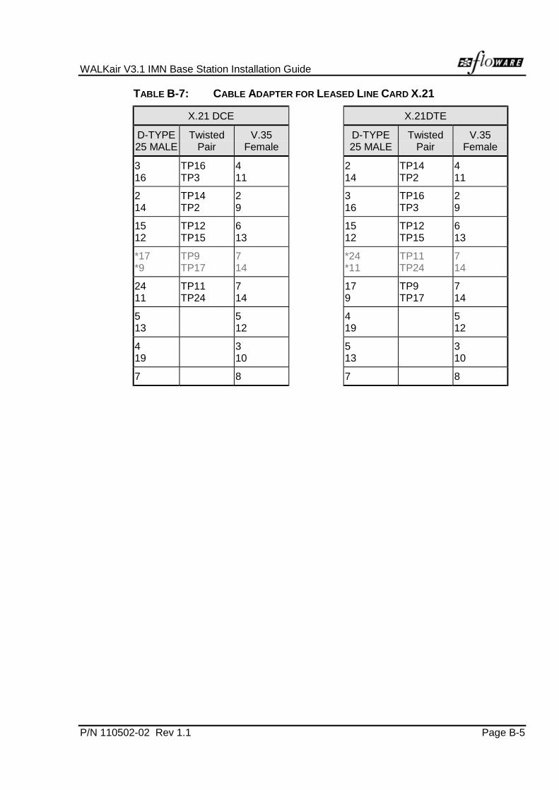
TABLE B-7: CABLE ADAPTER FOR LEASED LINE CARD X.21
X.21 DCE X.21DTE
D-TYPE25 MALE
TwistedPair
V.35Female
D-TYPE25 MALE
TwistedPair
V.35Female
316
TP16TP3
411
214
TP14TP2
411
214
TP14TP2
29
316
TP16TP3
29
1512
TP12TP15
613
1512
TP12TP15
613
*17*9
TP9TP17
714
*24*11
TP11TP24
714
2411
TP11TP24
714
179
TP9TP17
714
513
512
419
512
419
310
513
310
7 8 7 8

WALKair V3.1
IMN
Terminal Station Installation Guide
P/N 110502-03 D Rev 1.1
January 2000

TABLE OF CONTENTS
P/N 110502-03 Rev 1.1 Page i
TABLE OF CONTENTS
1 Introduction ............................................................................................. 1-11.1 Safety Precautions ....................................................................... 1-11.2 Components Sensitive to Electrostatic Discharge........................ 1-21.3 Additional Safety Requirements ................................................... 1-31.4 Parts List ...................................................................................... 1-41.5 Items not Supplied in Part List...................................................... 1-4
2 Site Preparation ...................................................................................... 2-12.1 Housings, Mountings, Dimensions and Clearance....................... 2-12.2 IF Cabling..................................................................................... 2-22.3 Powering and Earthing ................................................................. 2-2
3 Installation............................................................................................... 3-13.1 TS Installation Overview............................................................... 3-13.2 General Tips For RFU-TS Installation .......................................... 3-1
3.2.1 Inspection and Maintenance.................................................... 3-63.3 Mounting the 3.5 GHz or 10.5 GHz TS Antenna .......................... 3-7
3.3.1 3.5 GHz or 10.5 GHz RFU/Antenna ........................................ 3-73.3.2 Installing Mounting Adapter ..................................................... 3-7
3.4 Mounting the 26 GHz TS Dish Antenna ....................................... 3-93.4.1 Optional Mounting Configurations ..........................................3-14
3.5 IF Cable Connections................................................................. 3-153.5.1 RFU/Antenna Cable Connections...........................................3-16
3.6 TS-BU Mounting Bracket Attachment......................................... 3-173.6.1 Wall Mounting ........................................................................3-173.6.2 Desktop Mounting ..................................................................3-193.6.3 Rack Mounting (19" or ETSI racks) ........................................3-203.6.4 TS-BU Cable Connections .....................................................3-21
4 Initialization ............................................................................................. 4-14.1 Powering ON................................................................................ 4-14.2 Commissioning............................................................................. 4-14.3 Operating Temperature and Humidity .......................................... 4-1
Appendix A Terminal Station Connector Pinouts ........................................A-1

LIST OF FIGURES
Page ii P/N 110502-03 Rev 1.1
LIST OF FIGURES
Figure 1-1: ESD Graphic Symbol ............................................................................ 1-2Figure 1-2: EGB Graphic Symbol............................................................................ 1-3Figure 3-1: Roof Location for the ODU.................................................................... 3-2Figure 3-2: Clear Line of Sight Zone ....................................................................... 3-3Figure 3-3: Mounting Adapter.................................................................................. 3-7Figure 3-4: 26 GHz TS Dish Antenna (side view) .................................................... 3-9Figure 3-5: 26 GHZ TS Dish Antenna (top view) ................................................... 3-10Figure 3-6: Azimuth Adjustment Assembly............................................................ 3-10Figure 3-7: Elevation Adjustment Plate ................................................................. 3-11Figure 3-8: Antenna Mounting Plate...................................................................... 3-12Figure 3-9: Elevation adjustment........................................................................... 3-12Figure 3-10: Azimuth Adjustment Rod..................................................................... 3-13Figure 3-11: 2" Pole Mount (left or right) ................................................................. 3-14Figure 3-12: Connector Short Testing ..................................................................... 3-15Figure 3-13: Attaching the Mounting Brackets for Wall Mount ................................. 3-17Figure 3-14: Wall Mounting the TS-BU.................................................................... 3-18Figure 3-15: Desktop Mounting the TS-BU Base Unit ............................................. 3-19Figure 3-16: Mounting Bracket Attachment 19″ or ETSI.......................................... 3-20Figure 3-17: Rack Mounting the TS-BU .................................................................. 3-21Figure 3-18: Front Panel Connector Interface of the TS-BU.................................... 3-22Figure 3-19: Rear Panel Connector Interface of the TS-BU .................................... 3-22
LIST OF TABLES
Table 1-1: TS Parts List ......................................................................................... 1-4Table 3-1: Radius between beam center and obstacle for 3.5G [m] ...................... 3-4Table 3-2: Radius between beam center and obstacle or 10.5 GHz [m].............. 3-5Table 3-3: Nut Tightening Torque .......................................................................... 3-9Table 3-4: RF Cable Inter-connection .................................................................. 3-16Table 3-5: TS-BU Interfaces ................................................................................ 3-22Table 3-6: TS-BU Cable Inter-connection ............................................................ 3-23Table 4-1: TS Operating Temperature ................................................................... 4-1Table A-1: LCI Connector Pinout............................................................................A-1Table A-2: E1 Rx and Tx Cable Pinout...................................................................A-1Table A-3: DB-25 Connector Pin Assignment (DCE Mode) ....................................A-2Table A-4: Cable Adapter for Leased line Card V.35..............................................A-3Table A-5: Cable Adapter for Leased Line Card X.21.............................................A-4
P/N 110502-03 Rev 1.1 Page 1-1
1 INTRODUCTION
The WALKair V3.1 Terminal Station Installation Guide providesinstructions for service and installation technicians to facilitate installationof the WALKair V3.1 TS and its components.
It is assumed that you have general knowledge about the WALKair V3.1system as described in the WALKair V3.1 System Description.
Detailed instructions related to the operation of the WALKair V3.1 systemcan be seen in the WALKair V3.1 Service and Operation Guide.
NOTE
A site survey must be completed prior to the TS installation.(See the Site Preparation Guide for details).
1.1 Safety Precautions
High voltages are present at specific points in this electrical equipment.Some of the parts can also have high operating temperatures. Non-observance of these conditions and safety instructions can result inpersonal injury or in property damage.
The WALKair V3.1 system complies with the standard EN 60950. Allconnected equipment must comply with the applicable safety standards.
Equipment complies with the following EMC and safety standards:
• EN 50081-1
• EN 55022
• IEC 100-4-as 2, 3, 4, 5, 6, 8, 11
• ETSI 300339

Chapter 1. Introduction
Page 1-2 P/N 110502-03 Rev 1.1
To avoid injury and prevent equipment damage, observe the followingsafety precautions:
• Do not move or ship equipment unless it is properly packed in itsoriginal wrapping and shipping containers.
• When connecting equipment to the AC and DC voltage supplies,ensure correct polarity.
• Equipment service and maintenance should be undertaken only byWALKair V3.1 trained personnel.
• Ground the system units to prevent damage by lightning.
• Do not permit unqualified personnel to operate workstations used tocommunicate with the system.
1.2 Components Sensitive to ElectrostaticDischarge
All units that carry the Electrostatic Discharge sign (ESD), containcomponents sensitive to ESD and must comply with the necessaryregulations (see Figure 1-1).
FIGURE 1-1: ESD GRAPHIC SYMBOL
For units carrying the EGB symbol that are packed, unpacked, handled,extracted, or inserted, grounding brackets must always be worn. Thisensures that the units are not damaged (see Figure 1-2).
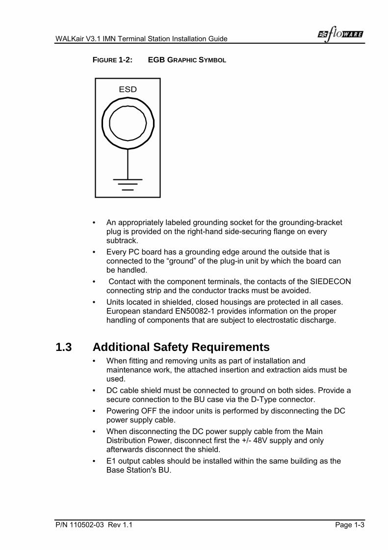
WALKair V3.1 IMN Terminal Station Installation Guide
P/N 110502-03 Rev 1.1 Page 1-3
FIGURE 1-2: EGB GRAPHIC SYMBOL
ESD
• An appropriately labeled grounding socket for the grounding-bracketplug is provided on the right-hand side-securing flange on everysubtrack.
• Every PC board has a grounding edge around the outside that isconnected to the “ground” of the plug-in unit by which the board canbe handled.
• Contact with the component terminals, the contacts of the SIEDECONconnecting strip and the conductor tracks must be avoided.
• Units located in shielded, closed housings are protected in all cases.European standard EN50082-1 provides information on the properhandling of components that are subject to electrostatic discharge.
1.3 Additional Safety Requirements• When fitting and removing units as part of installation and
maintenance work, the attached insertion and extraction aids must beused.
• DC cable shield must be connected to ground on both sides. Provide asecure connection to the BU case via the D-Type connector.
• Powering OFF the indoor units is performed by disconnecting the DCpower supply cable.
• When disconnecting the DC power supply cable from the MainDistribution Power, disconnect first the +/- 48V supply and onlyafterwards disconnect the shield.
• E1 output cables should be installed within the same building as theBase Station's BU.

Chapter 1. Introduction
Page 1-4 P/N 110502-03 Rev 1.1
1.4 Parts List
The following parts are supplied with the WALKair V3.1 system. In thecase of damage or missing parts, see the WALKair V3.1 SystemDocumentation Forward for related procedures. Table 1-1 contains theTS parts list.
TABLE 1-1: TS PARTS LIST
UNIT PARTS QUANTITY
TS-BU BU Mounting brackets 2
Rubber feet 4
TS RFU + Antenna(for 3.5 GHz and 10.5GHz only)
RFU-TS 3.5 GHzRFU–TS 10.5 GHzRFU–TS 26 GHz
111
Antenna 26 GHz-Parabolic dish 1
Mounting adapter 1
Mounting bands 2
1.5 Items not Supplied in Part List• Electric screwdriver (recommended)
• Coaxial cable between the indoor unit and the outdoor unit
• E1 cables
• LCI cables
• Connector sleeves
• IF cable (indoor/outdoor with 90° to the TS-BU(required to close the rack door)
• Rack screws
• Outdoor Strips
P/N 110502-03 Rev 1.1 Page 2-1
2 SITE PREPARATION
This section presents a description of the site preparation requirements,prior to installation of the WALKair V3.1 system.
TS site preparation should proceed in the following order:
1. Installation of the antenna mast (by installer)
2. Grounding the Mast
3. Install IF cable
2.1 Housings, Mountings, Dimensions andClearance
TS-BU units can be installed in the following:
• Standard 19" or ETSI racks
• Wall mounted
• Desk mounted
Width = 44 cm (19”)
Height = 1U (4.4 cm)
Depth = 23 cm
Weight 3 kg.

Chapter 2. Site Preparation
Page 2-2 P/N 110502-03 Rev 1.1
2.2 IF Cabling
A single coaxial cable (type LMR400 recommended), connects the outdoorequipment to the indoor TS-BU with an attenuation not greater than 20 dB.
Prepare all cabling prior to installation. Cable length and attenuation permeter should be determined prior to cable connection. Cable length is thedistance between antenna mast and TS-BU.
Determining cable attenuation in the field must include the following:
• Type of Cable
• Cable Length
• Attenuation per meter vs. frequency of the cable
2.3 Powering and Earthing
To prevent damage to the equipment, ensure that grounding cables areconnected to the Antenna/RFU.
Power is supplied to the TS-BU only, from an external power supply. Useeither a 110/220V AC or -48V DC power source.
Ensure that a separate grounding line is provided for the installedequipment and grounded to a central grounding point.

P/N 110502-03 Rev 1.1 Page 3-1
3 INSTALLATION
3.1 TS Installation Overview
The installation of the TS includes four main steps:
• Mounting the outdoor equipment
• RFU/Antenna alignment
• Installing the indoor equipment
• IF cable connector assembly and performing cable DC testing
• Supplying power to the TS-BU and verifying that the LEDs are lit
• Sealing ODU RF connectors for water resistance
3.2 General Tips For RFU-TS Installation• Never install the RFU near power lines.
• Assemble the RFU, bands and mounting adapter in a safe locationbefore climbing up to the mounting location. Use caution whenclimbing, and when working at the mounting location.
• Make sure you have determined the best location for the RFU polebefore mounting the pole. Make sure that you can route the IF cablefrom the location into the building.
• Before drilling any hole at the site building, make sure there are noelectrical wires in the area of the holes.
• All installations should conform to the local building and electricalcodes. If you are not sure, contact a licensed building inspector orelectrician in your area to assist you. Be aware that communityconventions, if any, may have additional requirements. Also, checkyour homeowner’s insurance policy for any restriction or expectationsthat may apply.
• Choose a location that is easily accessible in most weather conditionsfor proper maintenance.
• Consider seasonal changes. The location may appear clear in thewinter, but spring and summer foliage could dramatically attenuate thesignal.
• Do not install the RFU at the top of the pole; always leave at least40 cm space between the top of the pole and the RFU for betterlightning protection.
• Do not install the RFU where it can be blocked by people.
• The RFU and antenna must have a clear line-of-sight to the BaseStation. The RFU must be mounted so that the line-of-sight is clear ofneighboring buildings, trees, power lines and other obstructions. If you

Chapter 3. Installation
Page 3-2 P/N 110502-03 Rev 1.1
are mounting it on the middle of the roof, we recommend to install theRFU-TS at least 2 m above the lowest roof line (for example, the lineof the railing can be taken as a reference line), make sure that thereare no walls or blocks in front the RFU on the roof. If you need tomount the RFU on the wall of a building you must ensure that theRFU-TS will be at least ½ m away from the wall and no less than 15 mhigh from the ground.
• We recommend installing the RFU-TS at the corner of the roof 1mabove the railing and no less than 15 m high from the ground. Ifconditions exist that do not match the rules of a specific area theninstall it according to the above paragraph description(see Figure 3-1).
FIGURE 3-1: ROOF LOCATION FOR THE ODU
Leave at least40 cm space
between the top ofthe pole and theRFU for better
lightningprotection.
∙ We recommend toinstall the RFU-TS atthe corner of the roofwith 1 m above the
railing
Building
no less than15 m high from
the ground
The line-of-sight can be defined as no obstacle within a defined zonearound (vertical and horizontal) the antenna beam center. Zone widthdepends upon the distance between antennas. Table 3-1 shows the zone
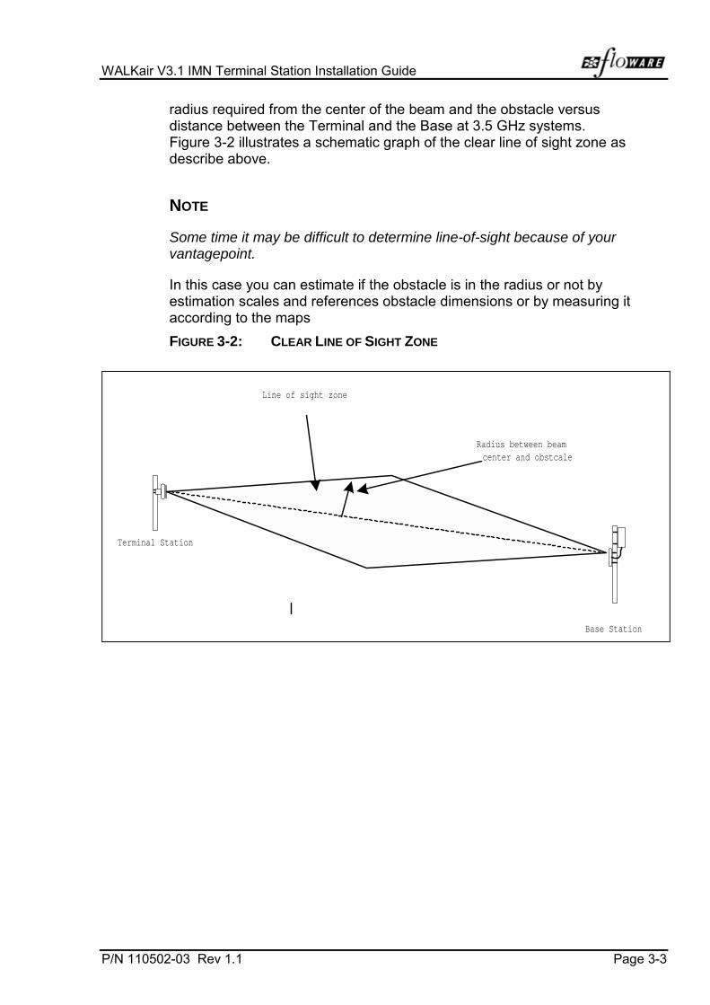
WALKair V3.1 IMN Terminal Station Installation Guide
P/N 110502-03 Rev 1.1 Page 3-3
radius required from the center of the beam and the obstacle versusdistance between the Terminal and the Base at 3.5 GHz systems.Figure 3-2 illustrates a schematic graph of the clear line of sight zone asdescribe above.
NOTE
Some time it may be difficult to determine line-of-sight because of yourvantagepoint.
In this case you can estimate if the obstacle is in the radius or not byestimation scales and references obstacle dimensions or by measuring itaccording to the maps
FIGURE 3-2: CLEAR LINE OF SIGHT ZONE
Line of sight zone
Radius between beamcenter and obstcale
Base Station
Terminal Station

Chapter 3. Installation
Page 3-4 P/N 110502-03 Rev 1.1
TABLE 3-1: RADIUS BETWEEN BEAM CENTER AND OBSTACLE FOR 3.5G [M]
Distance between Terminal and Base [ m ]
1 0 0 0 2 0 0 0 3 0 0 0 4 0 0 0 5 0 0 0 6 0 0 0 7 0 0 0 8 0 0 0 9 0 0 0 1 0 0 0 0
3 0 0 4 .2 4 .7 4 .8 4 .9 4 .9 4 .9 4 .9 5 .0 5 .0 5 .0
6 0 0 4 .5 6 .0 6 .4 6 .6 6 .7 6 .8 6 .8 6 .9 6 .9 6 .9
9 0 0 6 .5 7 .3 7 .7 7 .9 8 .1 8 .2 8 .2 8 .3 8 .3
1 2 0 0 6 .4 7 .8 8 .4 8 .8 9 .0 9 .2 9 .3 9 .4 9 .5
1 5 0 0 5 .6 8 .0 8 .9 9 .4 9 .8 1 0 .0 1 0 .2 1 0 .3 1 0 .4
1 8 0 0 7 .8 9 .2 9 .9 1 0 .3 1 0 .7 1 0 .9 1 1 .1 1 1 .2
2 1 0 0 7 .3 9 .2 1 0 .2 1 0 .8 1 1 .2 1 1 .5 1 1 .7 1 1 .9
2 4 0 0 6 .4 9 .0 1 0 .3 1 1 .1 1 1 .6 1 1 .9 1 2 .2 1 2 .5
2 7 0 0 4 .8 8 .6 1 0 .3 1 1 .2 1 1 .9 1 2 .3 1 2 .7 1 2 .9
3 0 0 0 8 .0 1 0 .1 1 1 .3 1 2 .1 1 2 .6 1 3 .0 1 3 .4
3 3 0 0 7 .0 9 .8 1 1 .2 1 2 .2 1 2 .8 1 3 .3 1 3 .7
3 6 0 0 5 .5 9 .3 1 1 .1 1 2 .2 1 3 .0 1 3 .5 1 4 .0
3 9 0 0 8 .5 1 0 .8 1 2 .1 1 3 .0 1 3 .7 1 4 .2
4 2 0 0 7 .6 1 0 .3 1 1 .9 1 3 .0 1 3 .8 1 4 .4
4 5 0 0 6 .2 9 .8 1 1 .7 1 2 .9 1 3 .8 1 4 .5
4 8 0 0 9 .0 1 1 .3 1 2 .8 1 3 .8 1 4 .6
5 1 0 0 8 .1 1 0 .8 1 2 .5 1 3 .7 1 4 .6
5 4 0 0 6 .8 1 0 .2 1 2 .2 1 3 .5 1 4 .5
5 7 0 0 4 .9 9 .5 1 1 .8 1 3 .3 1 4 .4
6 0 0 0 8 .5 1 1 .3 1 3 .0 1 4 .3
6 3 0 0 7 .3 1 0 .7 1 2 .7 1 4 .1
6 6 0 0 5 .7 9 .9 1 2 .2 1 3 .8
6 9 0 0 9 .0 1 1 .7 1 3 .5
7 2 0 0 7 .8 1 1 .1 1 3 .1
7 5 0 0 6 .3 1 0 .3 1 2 .6
7 8 0 0 9 .4 1 2 .1
8 1 0 0 8 .3 1 1 .4
8 4 0 0 6 .9 1 0 .7
8 7 0 0 5 .0 9 .8
9 0 0 0 8 .7
9 3 0 0 7 .4
9 6 0 0 5 .7
Possible interference:Generally, large reflecting surfaces in parallel or partly in the beam willcause reflections of the radio signal. For example, a metal/glass building,moist earth, water, and above ground metals like poles and telephonelines. If you have a clear line-of-sight as defined above the effect of thisinterference's will be minor.
The customer is responsible for ensuring that the preparations arecomplete and in accordance with national, state, and local codes.
Antenna alignment:In the 3.5 GHz systems, the AZIMUTH alignment of the antenna can bedone effectively using a compass and maps. Before you align the antennawith a compass you should be aware of deviation and declination errorscaused by magnetic objects and shifting of the real north magnetic filedrespectively. The deviation error can be avoided by ensuring that magneticobjects are located a safe distance away from the compass. Objects thatcause magnetic deviation include those containing steel, iron, or electricalcables with strong current. The declination problem can be avoided byusing a compass with declination adjustment and local maps with precisevalue of declination. According to this problem the compass calibrationmust be preformed before initial use to be accurate.
DistancebetweenTerminaland obstacle[ M ]

WALKair V3.1 IMN Terminal Station Installation Guide
P/N 110502-03 Rev 1.1 Page 3-5
TABLE 3-2: RADIUS BETWEEN BEAM CENTER AND OBSTACLE
OR 10.5 GHZ [M]
Distance between Terminal and Base [m]
1 0 0 0 2 0 0 0 3 0 0 0 4 0 0 0 5 0 0 0 6 0 0 0 7 0 0 0 8 0 0 0 9 0 0 0 1 0 0 0 0
3 0 0 2 .4 2 .7 2 .7 2 .8 2 .8 2 .8 2 .8 2 .8 2 .8 2 .9
6 0 0 2 .6 3 .4 3 .7 3 .8 3 .8 3 .9 3 .9 3 .9 4 .0 4 .0
9 0 0 3 .7 4 .2 4 .4 4 .5 4 .6 4 .7 4 .7 4 .8 4 .8
1 2 0 0 3 .7 4 .5 4 .8 5 .1 5 .2 5 .3 5 .3 5 .4 5 .4
1 5 0 0 3 .2 4 .6 5 .1 5 .4 5 .6 5 .7 5 .8 5 .9 6 .0
1 8 0 0 4 .5 5 .3 5 .7 5 .9 6 .1 6 .2 6 .3 6 .4
2 1 0 0 4 .2 5 .3 5 .8 6 .2 6 .4 6 .6 6 .7 6 .8
2 4 0 0 3 .7 5 .2 5 .9 6 .3 6 .6 6 .9 7 .0 7 .1
2 7 0 0 2 .7 5 .0 5 .9 6 .4 6 .8 7 .1 7 .3 7 .4
3 0 0 0 4 .6 5 .8 6 .5 6 .9 7 .2 7 .5 7 .7
3 3 0 0 4 .0 5 .6 6 .4 7 .0 7 .4 7 .6 7 .9
3 6 0 0 3 .2 5 .3 6 .3 7 .0 7 .4 7 .8 8 .0
3 9 0 0 4 .9 6 .2 7 .0 7 .5 7 .9 8 .2
4 2 0 0 4 .3 5 .9 6 .9 7 .5 7 .9 8 .3
4 5 0 0 3 .5 5 .6 6 .7 7 .4 7 .9 8 .3
4 8 0 0 5 .2 6 .5 7 .3 7 .9 8 .4
5 1 0 0 4 .6 6 .2 7 .2 7 .9 8 .4
5 4 0 0 3 .9 5 .9 7 .0 7 .8 8 .3
5 7 0 0 2 .8 5 .4 6 .8 7 .6 8 .3
6 0 0 0 4 .9 6 .5 7 .5 8 .2
6 3 0 0 4 .2 6 .1 7 .3 8 .1
6 6 0 0 3 .2 5 .7 7 .0 7 .9
6 9 0 0 5 .2 6 .7 7 .7
7 2 0 0 4 .5 6 .3 7 .5
7 5 0 0 3 .6 5 .9 7 .2
7 8 0 0 5 .4 6 .9
8 1 0 0 4 .8 6 .6
8 4 0 0 4 .0 6 .1
8 7 0 0 2 .8 5 .6
9 0 0 0 5 .0
9 3 0 0 4 .3
9 6 0 0 3 .3
NOTE
See Appendix for additional information about ODU installation.
DistancebetweenTerminalandobstacle[M]

Chapter 3. Installation
Page 3-6 P/N 110502-03 Rev 1.1
3.2.1 Inspection and Maintenance1. Before leaving the installation site, check that all hardware on the
Mount and Antenna are secure.
2. Check polarization option.
3. Inspection of the Antenna should be performed at least once a year tocheck its condition and to ensure safe operation and maintenance.Qualified personnel, knowledgeable and experienced in antennainstallation are required for the inspection.

WALKair V3.1 IMN Terminal Station Installation Guide
P/N 110502-03 Rev 1.1 Page 3-7
3.3 Mounting the 3.5 GHz or 10.5 GHz TS Antenna
3.3.1 3.5 GHz or 10.5 GHz RFU/Antenna
The 3.5 or 10.5 RFU/Antenna is mounted on a mast with adjustablemounting grip and bands. The front panel of the TS RFU (i.e., the side notattached to the mounting adapter) is designed to prevent accumulation ofrainwater, which would cause damage to the unit. The mounting adaptercan be oriented in any direction relative to the pole (i.e., 90o, 180o, 270o,and 360o). Before attaching the RFU to the mounting adapter, make surethat the connector is pointing downward.
3.3.2 Installing Mounting Adapter
Figure 3-3 illustrates the Mounting Adapter.
FIGURE 3-3: MOUNTING ADAPTER
3
1
2
4
Elevation nut and screw
Azimutht nut and screw
Openings for bands

Chapter 3. Installation
Page 3-8 P/N 110502-03 Rev 1.1
To Install the Mounting Adapter:
1. Open the packaging and remove the mounting adapter.
2. Insert two bands in the designated slots.
3. Place the RFU upside-down on a clean desktop with the antennasurface facing down.
4. Place the mounting adapter on top of the RFU (located on the rear sideof the Antenna) with the spring on top.
5. Connect the mounting Adapter to the backside of the RFU with four10-mm screws.
6. Slightly loosen all screws and adjust the tilt/elevation using thedesignated screws:
! To adjust the elevation, swivel the long screw (marked 1 in figure)located on the bottom of the adapter. When the elevation isproperly directed, tighten the two screws (marked 2) on both sidesof the adapter.
! To adjust the Azimuth, swivel the long screw (marked 3) locatedon the left side of the adapter. When the tilt is properly directed,tighten the two screws(marked 4) on the top and the bottom of the adapter.
NOTE:
Each ¼ turn of the Azimuth /elevation screws is equivalent to 0.5o
(½ degree). Azimuth adjustment range is 20 o degrees, and elevationadjustment range is ±21o (total of 42o).
7. Position the RFU on the mast at the desired location, aligning the mastinto the designated mounting adapter slot. The mounting adapter slot isdesigned to fit a wide range of masts. The band will fit any mast up to110-mm diameter. Use an electrical screwdriver to tighten the bandsaround the mast.
8. Ground the RFU to the mast using the grounding pin (N6 diameter)located at the rear panel of the RFU/Antenna
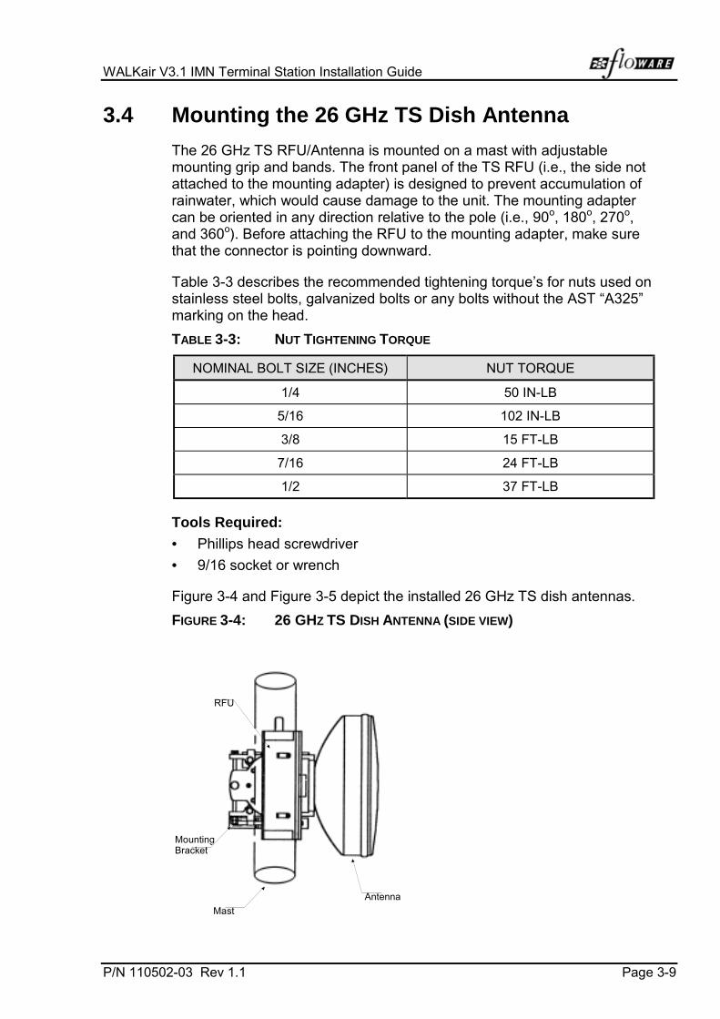
WALKair V3.1 IMN Terminal Station Installation Guide
P/N 110502-03 Rev 1.1 Page 3-9
3.4 Mounting the 26 GHz TS Dish Antenna
The 26 GHz TS RFU/Antenna is mounted on a mast with adjustablemounting grip and bands. The front panel of the TS RFU (i.e., the side notattached to the mounting adapter) is designed to prevent accumulation ofrainwater, which would cause damage to the unit. The mounting adaptercan be oriented in any direction relative to the pole (i.e., 90o, 180o, 270o,and 360o). Before attaching the RFU to the mounting adapter, make surethat the connector is pointing downward.
Table 3-3 describes the recommended tightening torque’s for nuts used onstainless steel bolts, galvanized bolts or any bolts without the AST “A325”marking on the head.
TABLE 3-3: NUT TIGHTENING TORQUE
NOMINAL BOLT SIZE (INCHES) NUT TORQUE
1/4 50 IN-LB
5/16 102 IN-LB
3/8 15 FT-LB
7/16 24 FT-LB
1/2 37 FT-LB
Tools Required:
• Phillips head screwdriver
• 9/16 socket or wrench
Figure 3-4 and Figure 3-5 depict the installed 26 GHz TS dish antennas.
FIGURE 3-4: 26 GHZ TS DISH ANTENNA (SIDE VIEW)
Mast
MountingBracket
RFU
Antenna

Chapter 3. Installation
Page 3-10 P/N 110502-03 Rev 1.1
FIGURE 3-5: 26 GHZ TS DISH ANTENNA (TOP VIEW)
Mast
MountingBracket
RFU
Antenna
Installation of the mounting brackets for the 26 GHz TS Dish Antennaallows the antenna to be accurately positioned on the mast for optimumreception. The following components must be installed in sequence:
Step 1:Azimuth Adjustment Assembly
The Azimuth Adjustment Assembly is the first bracket to be attached to themast. This is done with two bronze lock nuts and washers as shown inFigure 3-6.
FIGURE 3-6: AZIMUTH ADJUSTMENT ASSEMBLY
3/8 X 16 BronzeNut With Locksand Flats(2) Places
Note: Location ofAzimuth Adjust Hole

WALKair V3.1 IMN Terminal Station Installation Guide
P/N 110502-03 Rev 1.1 Page 3-11
To Install the Azimuth Adjusting Assembly:
1. Attach the Azimuth Adjusting Assembly adjustment plate to the mast.
2. Align the plate so that the antenna will face in the required direction.
3. Secure the azimuth adjustment plate by tightening the silicone-bronzelock nuts.
Step2:Elevation Adjustment Plate
The Elevation Adjustment Plate allows the antenna to be tilted up or downusing a vertical adjustment rod as seen in Figure 3-7.
FIGURE 3-7: ELEVATION ADJUSTMENT PLATE
Pole MountPlate Assy.
(2) Clamp Bars
(4Pcs)3/8 Flat Galvanized
3/8-16 Hex Nut Galv.3/8-16 Split Galv.
Washers
3/8 X 16 Galvanized NutW/ Lock + Flat
Washers Both Sides.
Azimuth Adjust Rod
To Install the Elevation Adjustment Plate:
1. Secure the mounting plate to the mast using 2 clamp bars(P/N 101459-1).
2. Position the clamp bars as shown in Figure 3-7.
3. Position the azimuth-adjusting rod through the adjusting plate beforetightening the nuts.
4. Tighten the 2 clamp bars so that the elevation adjustment plate is snugagainst the mast.

Chapter 3. Installation
Page 3-12 P/N 110502-03 Rev 1.1
Step 3:The Antenna Mounting Plate
The Antenna Mounting Plate attaches directly to the antenna assemblyand allows for fine-tuning of the antenna position (see Figure 3-8).
FIGURE 3-8: ANTENNA MOUNTING PLATE
I ns ta l l 1 /4 -20S c r e w s i n t o Mounting Bracketthat is Attachedt o A n t e n n a .
To install the Antenna Mounting Plate:
• Attach the mini-elevation adjustment plate to the Elevation AdjustmentPlate using 2 ¼-20 x ¾ inch pan head screws with stainless steel splitlock washers as shown in Figure 3-8.
Step 4:Elevation Adjustment
Elevation is adjusted for lookdown angles using the vertical threadedadjustment rod as shown in Figure 3-9.
FIGURE 3-9: ELEVATION ADJUSTMENT
3/8 bolts with lock and flatswith nylon washer againsta d j u s t m e n t p l a t e
Brass Rod

WALKair V3.1 IMN Terminal Station Installation Guide
P/N 110502-03 Rev 1.1 Page 3-13
To Adjust the Antenna Elevation:
1. Lookdown angle is adjusted by positioning the threaded brassadjustment rod in the lower hole of the elevation adjustment plate.
• The two 3/8 bolts should be tightened until the antenna is snugagainst the adjustment plate.
• Elevation is adjusted by turning the threaded elevation adjustmentrod.
• After final adjustment, fully tighten the (2) 3/8 bolts.
Step 5:Azimuth Coordinates
To Adjust the Azimuth using the azimuth adjusting rod:
1. The Azimuth Adjustment Assembly should be snug against the mast.
2. Turn the Galvanized nut on the azimuth rod until the required position isreached (see Figure 3-10).
3. Fully tighten the lock nut on the adjustment rod.
FIGURE 3-10: AZIMUTH ADJUSTMENT ROD
AzimuthAdjustment Rod
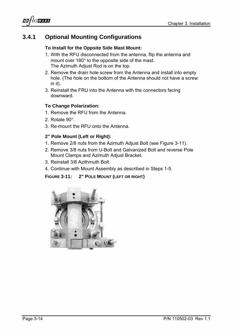
Chapter 3. Installation
Page 3-14 P/N 110502-03 Rev 1.1
3.4.1 Optional Mounting Configurations
To Install for the Oppsite Side Mast Mount:
1. With the RFU disconnected from the antenna, flip the antenna andmount over 180° to the opposite side of the mast.The Azimuth Adjust Rod is on the top.
2. Remove the drain hole screw from the Antenna and install into emptyhole. (The hole on the bottom of the Antenna should not have a screwin it).
3. Reinstall the FRU into the Antenna with the connectors facingdownward.
To Change Polarization:
1. Remove the RFU from the Antenna.
2. Rotate 90°.3. Re-mount the RFU onto the Antenna.
2" Pole Mount (Left or Right):
1. Remove 2/8 nuts from the Azimuth Adjust Bolt (see Figure 3-11).
2. Remove 3/8 nuts from U-Bolt and Galvanized Bolt and reverse PoleMount Clamps and Azimuth Adjust Bracket.
3. Reinstall 3/8 Azithmuth Bolt.
4. Continue with Mount Assembly as described in Steps 1-5.
FIGURE 3-11: 2" POLE MOUNT (LEFT OR RIGHT)
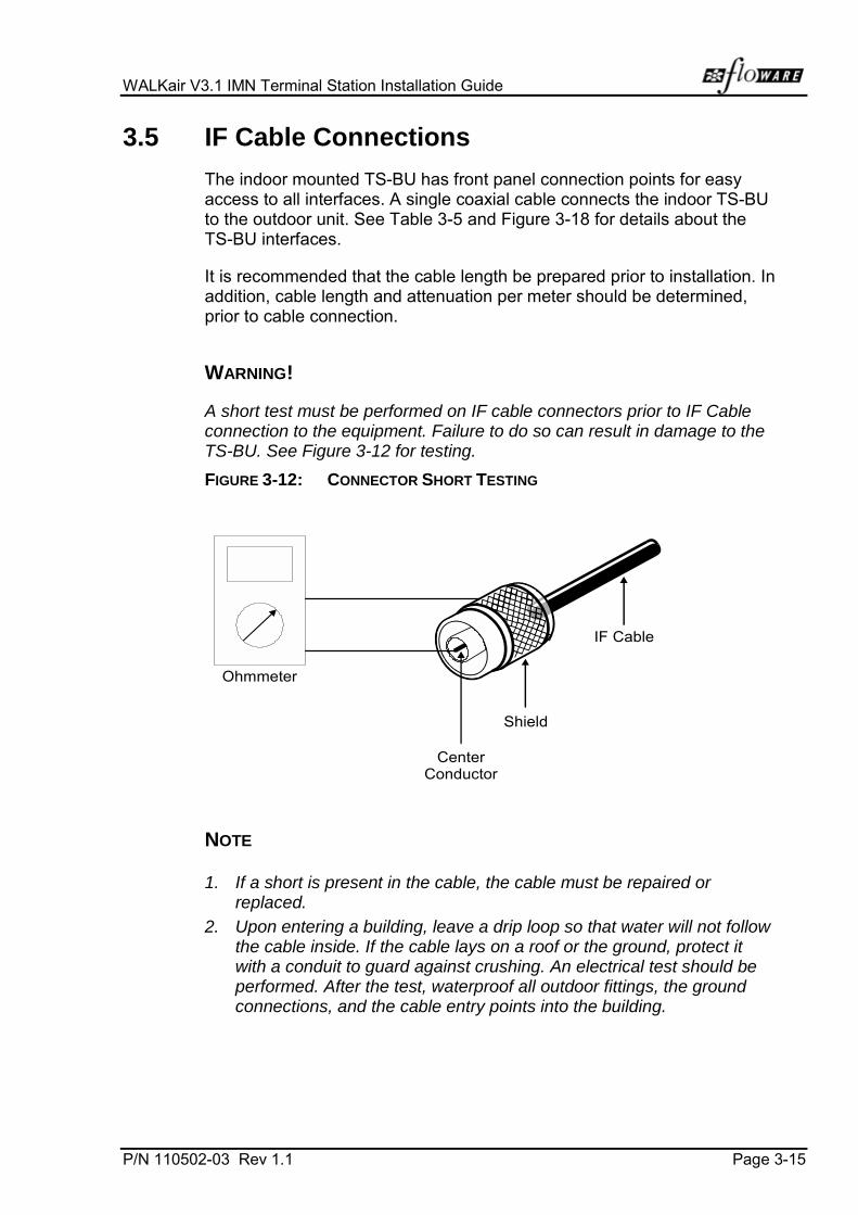
WALKair V3.1 IMN Terminal Station Installation Guide
P/N 110502-03 Rev 1.1 Page 3-15
3.5 IF Cable Connections
The indoor mounted TS-BU has front panel connection points for easyaccess to all interfaces. A single coaxial cable connects the indoor TS-BUto the outdoor unit. See Table 3-5 and Figure 3-18 for details about theTS-BU interfaces.
It is recommended that the cable length be prepared prior to installation. Inaddition, cable length and attenuation per meter should be determined,prior to cable connection.
WARNING!
A short test must be performed on IF cable connectors prior to IF Cableconnection to the equipment. Failure to do so can result in damage to theTS-BU. See Figure 3-12 for testing.
FIGURE 3-12: CONNECTOR SHORT TESTING
Shield
CenterConductor
Ohmmeter
IF Cable
NOTE
1. If a short is present in the cable, the cable must be repaired orreplaced.
2. Upon entering a building, leave a drip loop so that water will not followthe cable inside. If the cable lays on a roof or the ground, protect itwith a conduit to guard against crushing. An electrical test should beperformed. After the test, waterproof all outdoor fittings, the groundconnections, and the cable entry points into the building.

Chapter 3. Installation
Page 3-16 P/N 110502-03 Rev 1.1
Determining cable attenuation in the field must include the following:
• Cable length
• Attenuation per meter of the cable Vs frequency (600 MHz – 1.8 GHz).This can be determined by using a cable data sheet.
3.5.1 RFU/Antenna Cable Connections
The TS RFU/Antenna is connected to the TS-BU by a single coaxial cableas described in Table 3-4. Table 3-4 details the point-to-point cableconnection.
TABLE 3-4: RF CABLE INTER-CONNECTION
CABLE FROM TO NOTE
COAX LMR400(Recommended cable)
Ant/RFU TS-BU Maximum 150 m
• For cable lengths greater than 150 m, use a higher quality cable thanthe LMR400. Total cable attenuation must not exceed 20 dB,regardless of cable length.
NOTE
• The IF cable connector must be a certified outdoor connector.
• The outdoor connectors should be tightened using sleeves.
• After installation, all outdoor cable connections must be sealed withwaterproof materials
NOTE
When routing the coaxial cable, leave a service loop at the antenna sothere will sufficient length of cable to replace a faulty connector, whennecessary. Secure the coax so that there is no mechanical stress at theantenna connection. Follow the super structure with the cable to its baseto the building. If the cable requires suspension from the base to thebuilding, use a stranded wire to support the cable weight. (The support willprevent a migration of the cable's inner conductor to the shield).
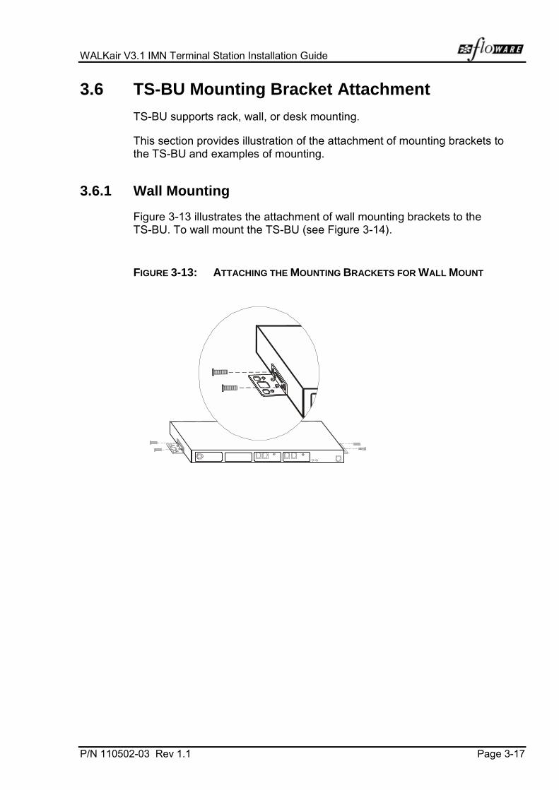
WALKair V3.1 IMN Terminal Station Installation Guide
P/N 110502-03 Rev 1.1 Page 3-17
3.6 TS-BU Mounting Bracket Attachment
TS-BU supports rack, wall, or desk mounting.
This section provides illustration of the attachment of mounting brackets tothe TS-BU and examples of mounting.
3.6.1 Wall Mounting
Figure 3-13 illustrates the attachment of wall mounting brackets to theTS-BU. To wall mount the TS-BU (see Figure 3-14).
FIGURE 3-13: ATTACHING THE MOUNTING BRACKETS FOR WALL MOUNT

Chapter 3. Installation
Page 3-18 P/N 110502-03 Rev 1.1
FIGURE 3-14: WALL MOUNTING THE TS-BU

WALKair V3.1 IMN Terminal Station Installation Guide
P/N 110502-03 Rev 1.1 Page 3-19
3.6.2 Desktop Mounting
The TS-BU comes with four miniature support legs for the desktop option.Attach the support legs and place on a clean, flat surface.
Figure 3-15 illustrates a desktop mounted TS-BU.
FIGURE 3-15: DESKTOP MOUNTING THE TS-BU BASE UNIT

Chapter 3. Installation
Page 3-20 P/N 110502-03 Rev 1.1
3.6.3 Rack Mounting (19" or ETSI racks)
The TS equipment can be installed in the following types of racks:
• ETSI
• 19"
The TS-BUs are supplied with rack mounting brackets suitable forinstallation in both rack types.
TS equipment can be installed in racks using horizontal mounting.
Figure 3-16 illustrates the attachment of mounting brackets for standard19"of ETSI rack. Figure 3-17 illustrates rack mounting the TS-BU.
FIGURE 3-16: MOUNTING BRACKET ATTACHMENT 19″″″″ OR ETSI

WALKair V3.1 IMN Terminal Station Installation Guide
P/N 110502-03 Rev 1.1 Page 3-21
FIGURE 3-17: RACK MOUNTING THE TS-BU
To Mount the TS-BUs:
1. Ground the rack in accordance with the local standards.
2. Attach mounting brackets to the TS-BUs.
3. Insert the TS-BUs as shown in Figure 3-17 using two screws at eachside to attach the BUs to the rack.
Connect the earth ground to the ground screw of each TS-BU. The groundscrew is located on the rear panel of the TS-BU. The ground pin diameteris MC8.
3.6.4 TS-BU Cable Connections
The TS-BU front panel provides interfaces to the RFU/Antenna, theTelecom services and the Local Craft.
Figure 3-18 and Figure 3-19 illustrates the front and rear panels of theTS-BU. Table 3-6 details the point- to-point cable connection.

Chapter 3. Installation
Page 3-22 P/N 110502-03 Rev 1.1
FIGURE 3-18: FRONT PANEL CONNECTOR INTERFACE OF THE TS-BU
Tx
Local Craft Interface (LCI)
Management SystemLED Status Indicators
Public Switch Interfaces(1 - 3)
IF PortsN-Type
Internal ExternalRx / TX48V DC
TX TX RXRX
FIGURE 3-19: REAR PANEL CONNECTOR INTERFACE OF THE TS-BU
Ground PinPower Input
48V DCD-Type
Ground PinPower Input
110/220V ACIEC Socket
TABLE 3-5: TS-BU INTERFACES
PORT TYPE DESCRIPTION
LCI RJ45 Provides an interface to a localcraft terminal.
Telecom Ports(1 to 3)
RJ45 Each port provides the interfaceto a 2 Mbps channel.
IF Ports N-Type Provides the interface to theRFU
Power(located on rear panel)
3-Pin IEC SocketOR
D-Type
Provides operating power to theTS-BU using 110/220V ACOR
-48V DC operating power
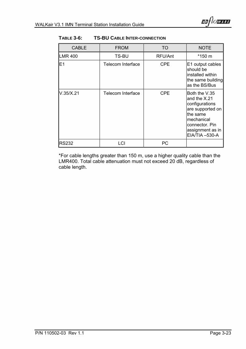
WALKair V3.1 IMN Terminal Station Installation Guide
P/N 110502-03 Rev 1.1 Page 3-23
TABLE 3-6: TS-BU CABLE INTER-CONNECTION
CABLE FROM TO NOTE
LMR 400 TS-BU RFU/Ant *150 m
E1 Telecom Interface CPE E1 output cablesshould beinstalled withinthe same buildingas the BS/Bus
V.35/X.21 Telecom Interface CPE Both the V.35and the X.21configurationsare supported onthe samemechanicalconnector. Pinassignment as inEIA/TIA –530-A
RS232 LCI PC
*For cable lengths greater than 150 m, use a higher quality cable than theLMR400. Total cable attenuation must not exceed 20 dB, regardless ofcable length.


P/N 110502-03 Rev 1.1 Page 4-1
4 INITIALIZATION
4.1 Powering ON
Either a standard 110/220V AC or -48V DC source powers the TS. Asdescribed in the Terminal Station Preparation Guide, the power distributionpanel isolation switch is used to power on the TS-BUs.
4.2 Commissioning
Please see instructions provided in the Commissioning Guide.
4.3 Operating Temperature and Humidity
Table 4-1 describes the TS operating temperature and humidityspecifications.
TABLE 4-1: TS OPERATING TEMPERATURE
ITEM SPECIFICATION
Indoor Equipment Subject to normal indoor temperature andhumidity conditions: +5°C to +45°C
Outdoor Equipment Subject to standard European outdoorconditions: -45°C to +55°C


P/N 110502-03 Rev 1.1 Page A-1
Appendix A TERMINAL STATION CONNECTOR PINOUTS
The following tables describe the pin assignments for the Terminal StationRJ-45 connectors.
TABLE A-1: LCI CONNECTOR PINOUT
PIN DESCRIPTION
1 Shield
2 Rx
3 Tx
4 Shield
5 GND
6 Shield
7 Shield
8 Shield
TABLE A-2: E1 RX AND TX CABLE PINOUT
PIN DESCRIPTION
1 Shield
2 Shield
3 Tip
4 Ring
5 Shield
6 Shield
7 Shield
8 Shield

Chapter 4. Initialization
Page A-2 P/N 110502-03 Rev 1.1
TABLE A-3: DB-25 CONNECTOR PIN ASSIGNMENT (DCE MODE)
PIN NO. GROUP NAME DIRECTION(DCE)
SIGNALDESCRIPTION
1 PWR SHIELD -
2 DATA TD (A) 103 IN
3 DATA RD (A) 104 OUT
4 CTRL RTS 105 IN C in x.21
5 CTRL CTS 106 OUT
6 CTRL DSR 107 OUT
7 PWR GND -
8 CTRL DCD 109 OUT I in X.21
9 CLK RC (B) 115 OUT CK for RD, from DCE
10 CTRL DCD 2 109/2 OUT I in X.21
11 CLK TTC (B) 113 IN CK for TD, from DTE
12 CLK TC (C) 114 OUT CK for TD, from DCE
13 CTRL CTS 2 106/2 OUT
14 DATA TD (B) 103 IN
15 CLK TC (A) 114 OUT
16 DATA RD (B) 104 OUT
17 CLK RC (A) 115 OUT
18 TEST LL 141 IN
19 CTRL RTS 2 105 IN C in X.21
20 CTRL DTR 108 IN
21 TEST RL 140 IN
22 CTRL DSR 2 107 OUT
23 CTRL DTR 2 108 IN
24 CLK TTC (A) 113 IN
25 TEST TM 142 OUT
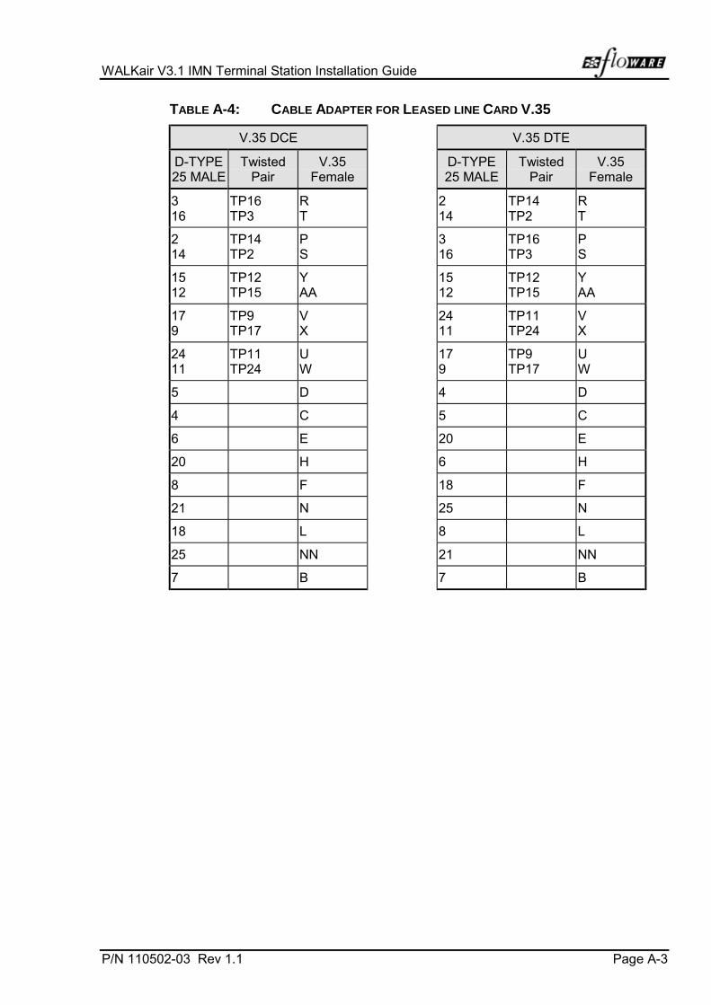
WALKair V3.1 IMN Terminal Station Installation Guide
P/N 110502-03 Rev 1.1 Page A-3
TABLE A-4: CABLE ADAPTER FOR LEASED LINE CARD V.35
V.35 DCE V.35 DTE
D-TYPE25 MALE
TwistedPair
V.35Female
D-TYPE25 MALE
TwistedPair
V.35Female
316
TP16TP3
RT
214
TP14TP2
RT
214
TP14TP2
PS
316
TP16TP3
PS
1512
TP12TP15
YAA
1512
TP12TP15
YAA
179
TP9TP17
VX
2411
TP11TP24
VX
2411
TP11TP24
UW
179
TP9TP17
UW
5 D 4 D
4 C 5 C
6 E 20 E
20 H 6 H
8 F 18 F
21 N 25 N
18 L 8 L
25 NN 21 NN
7 B 7 B
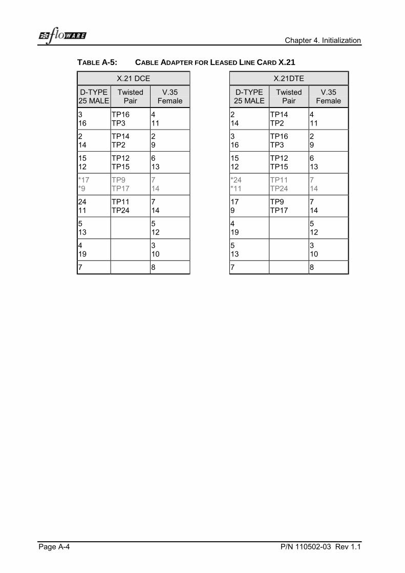
Chapter 4. Initialization
Page A-4 P/N 110502-03 Rev 1.1
TABLE A-5: CABLE ADAPTER FOR LEASED LINE CARD X.21
X.21 DCE X.21DTE
D-TYPE25 MALE
TwistedPair
V.35Female
D-TYPE25 MALE
TwistedPair
V.35Female
316
TP16TP3
411
214
TP14TP2
411
214
TP14TP2
29
316
TP16TP3
29
1512
TP12TP15
613
1512
TP12TP15
613
*17*9
TP9TP17
714
*24*11
TP11TP24
714
2411
TP11TP24
714
179
TP9TP17
714
513
512
419
512
419
310
513
310
7 8 7 8