
IMAGENEX TECHNOLOGY CORPimagenex.com/assets/images/downloads/852ES11000m_manual.pdf · various...
36
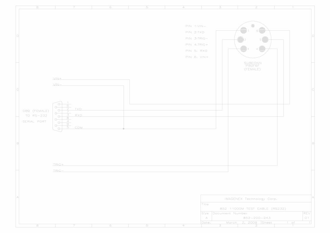
IMAGENEX TECHNOLOGY CORP. MODEL 852-000-145 ULTRA-MINIATURE DIGITAL ECHO SOUNDER ECHO SOUNDER S/N _____________ IS CONFIGURED FOR: _______________ VDC INPUT ______________ @ 115.2 kbps IMAGENEX TECHNOLOGY CORP. 209-1875 BROADWAY STREET PORT COQUITLAM, B.C. CANADA, V3C 4Z1 TEL: (604) 944-8248 FAX: (604) 944-8249
Transcript of IMAGENEX TECHNOLOGY CORPimagenex.com/assets/images/downloads/852ES11000m_manual.pdf · various...
IMAGENEX TECHNOLOGY CORP.
MODEL 852-000-145ULTRA-MINIATURE DIGITAL
ECHO SOUNDER
ECHO SOUNDER S/N _____________
IS CONFIGURED FOR:
_______________ VDC INPUT
______________ @ 115.2 kbps
IMAGENEX TECHNOLOGY CORP.209-1875 BROADWAY STREET
PORT COQUITLAM, B.C.CANADA, V3C 4Z1
TEL: (604) 944-8248FAX: (604) 944-8249
852 Echo Sounder 11000 m 445-060 MARCH 2009-REVISED MAY 2017
Specifications subject to
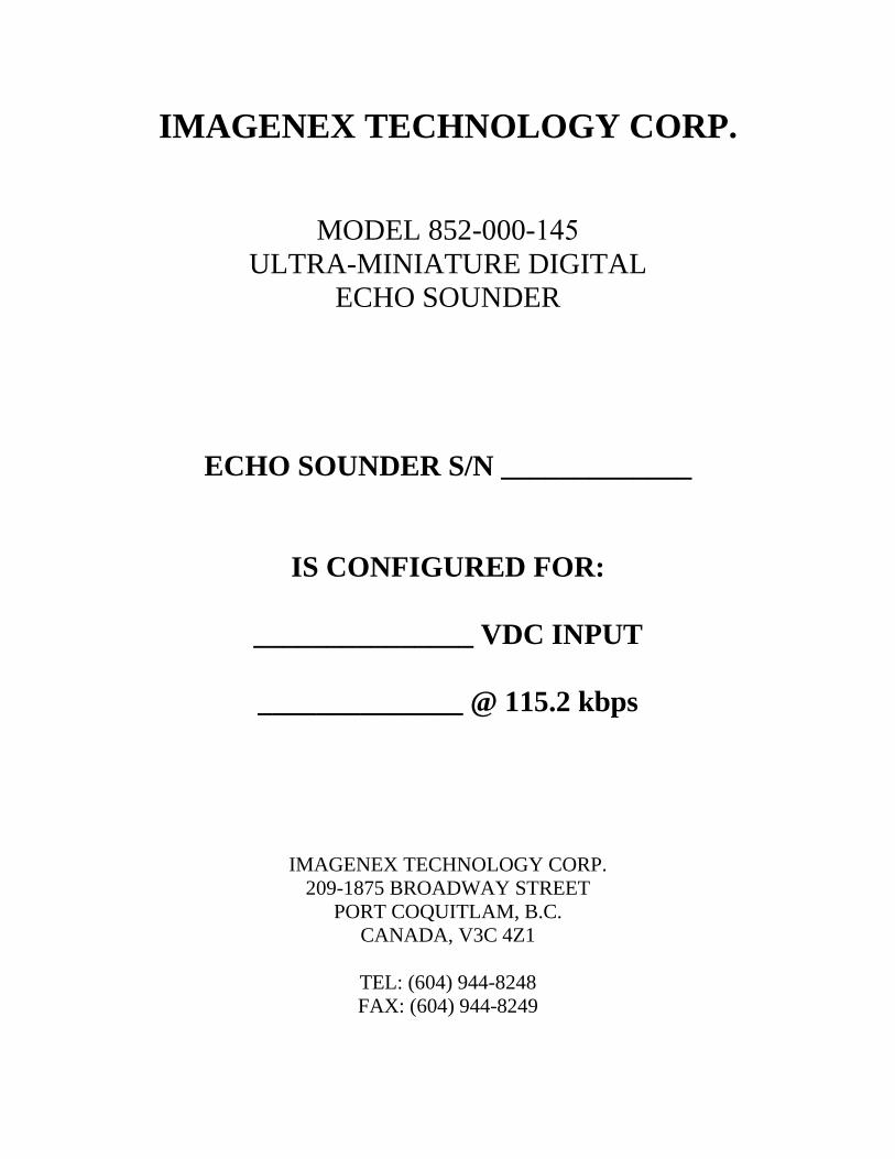
IMAGENEX MODEL 852 ULTRA-MINIATURE 11000 m ECHO SOUNDER
APPLICATIONS: FEATURES:
• ROV Navigation • Ultra-miniature size is ideal for mounting • Diving Support on today’s micro ROV’s • Inspection • Low cost • Search & Recovery • Direct connection to laptop computer • External trigger available
The Model 852 Digital Echo Sounder was designed for use with the smallest of ROV’s. For maximum flexibility, the unit requires approximately 1.5 Watts from 24 VDC, or optional 48 VDC. Serial communication is utilized, RS-485 or RS-232 at 115.2 kbps. The maximum operating range is 50 meters.
HARDWARE SPECIFICATIONS: FREQUENCY 330 kHz TRANSDUCER BEAM WIDTH 30° Conical RANGE RESOLUTION 20 mm MIN. DETECTABLE RANGE 500 mm MAX. OPERATING DEPTH 11000 m MAX. CABLE LENGTH 1000 m on typical twisted shielded pair INTERFACE RS-485 @ 115.2 kbps (RS-232 optional) CONNECTOR BH6M-Titanium POWER SUPPLY 22 – 30 VDC at less than 1.5 Watts
Optional 40 – 56 VDC DIMENSIONS See drawing WEIGHT: In Air In Water
~913 g (~2 lbs) ~0.75 kg (~1.7 lbs)
MATERIALS 6AL4V Titanium, PVC, Epoxy FINISH Natural
Copyright © 2009 - 2018 change without notice www.imagenex.com Imagenex Technology Corp.
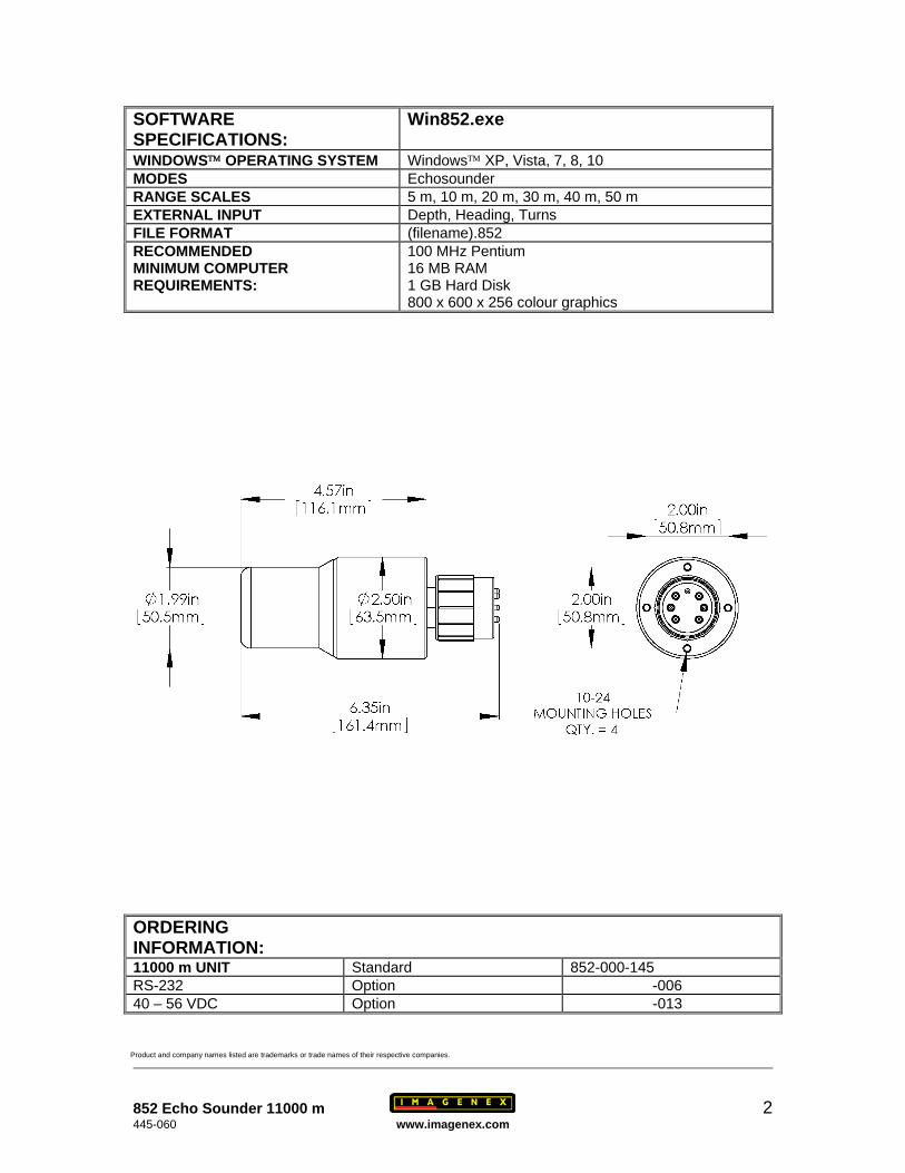
SOFTWARE SPECIFICATIONS:
Win852.exe
WINDOWS™ OPERATING SYSTEM Windows™ XP, Vista, 7, 8, 10 MODES Echosounder RANGE SCALES 5 m, 10 m, 20 m, 30 m, 40 m, 50 m EXTERNAL INPUT Depth, Heading, Turns FILE FORMAT (filename).852 RECOMMENDED MINIMUM COMPUTER REQUIREMENTS:
100 MHz Pentium 16 MB RAM 1 GB Hard Disk 800 x 600 x 256 colour graphics
ORDERING INFORMATION: 11000 m UNIT Standard 852-000-145 RS-232 Option -006 40 – 56 VDC Option -013
Product and company names listed are trademarks or trade names of their respective companies.
852 Echo Sounder 11000 m 2 445-060 www.imagenex.com

Page 1 of 10
IMAGENEX TECHNOLOGY CORP. 18FEB16
MODEL 852 ULTRA-MINIATURE DIGITAL
SCANNING SONAR HEAD
and ECHO SOUNDER
WIN852.EXE: Display Software For Windows XP/Vista/7/8/10
VERSION 2.09
OVERVIEW
WIN852 is a Windows program that controls, displays and records data from the Model
852 Ultra-Miniature Digital Scanning Sonar Head and/or the Model 852 Ultra-Miniature
Digital Echo Sounder. The program uses a 2-Wire RS-485 COM port (115200,N,8,1) to
communicate with the heads and an RS-232 COM port (38400,N,8,1) for receiving
Remotely Operated Vehicle (ROV) information such as Depth, Heading and Turns
Count. The heads can be operated at different ranges, gains, pulse lengths, etc. The
Windows display mode must be at least 800 x 600 pixels with a small font.
SCREEN LAYOUT
The main screen of WIN852 comprises of a sonar data window on the left side with
various sonar head controls and a sector size icon on the right side. The echo sounder
window overlays the sonar window and is expandable. Other items include a x2 Pixel
Zoom window, date/time readout, Depth/Heading/Turns readout, sonar head
range/bearing readout to one or two cursors and a control for displaying real time data
from the heads or playback data from a file. A pop-up window is available for displaying
diagnostics. A compass rose can be displayed in place of the pixel zoom window.
OPERATION
To operate the sonar head and echo sounder, ensure that the head cable is connected to
the 2-Wire RS-485 serial port or an RS-485 to RS-232 converter is installed in-line.
Connect 22 to 30VDC to the power wires (+V to RED, -V to BLACK) using a DC power
supply capable of supplying a current of 1 Amp. Run the program WIN852.EXE and
select the button DATA FROM 'HEAD' on the right-hand side of the display. Ensure that
the correct COM port is selected (Com Ports Menu) and depending on the RS-485 serial
i/o card installed in your computer, select AUTO Enable or RTS (Request To Send)
Enable. Also ensure that the sonar head and/or echo sounder is enabled via the Set
Switches Dialog Box. To allow other programs to use available CPU time, WIN852 can
be put into standby mode simply by minimizing the main window.
Page 2 of 10
MAIN MENU
File Menu
Record Start (Stop)... opens a File Name Dialog Box so the user can input a
filename for logging sonar and/or echo sounder data (shot
by shot) complete with date/time stamp. The file
extension is always '.852'. The filename and current size
(kbytes) of the file are displayed at the top of the screen.
File recording continues until Record Stop is selected.
Available only when DATA FROM 'HEAD' is active.
Playback... opens a File Name Dialog Box so the user can select and
playback a previously recorded '.852' Sonar file. Available
only when DATA FROM 'FILE' is active.
Copy Start (Stop)... opens a File Name Dialog Box so the user can enter a
filename for a new ‘.852’ file that can be used for making
smaller data files from large pre-recorded sonar files. The
filename and current size (kbytes) of the file are displayed
at the top of the screen. File copying continues until Copy
Stop is selected. Available when DATA FROM 'FILE' is
active.
Save Screen... opens a File Name Dialog Box so the user can enter a
filename for saving the screen as a '.BMP' bitmap file.
Exit writes current configuration to file (WIN852.INI), closes
the program and exits to Windows.
Color Table Menu
Norm Hi normal high intensity color table used for mapping the
echo data amplitude to a color for display. Color depth is
107 colors ranging from Black (low level) through Blue,
Green, Orange, Yellow, White and Red (max level).
Norm Lo normal low intensity color table.
Green 107 shades of green.
Grey 107 shades of grey (White on Black).
Rev Grey 107 shades of grey (Black on White).
Brown/Yellow 107 mixed shades of brown and yellow.
Green/Blue 107 mixed shades of green and blue.
Green/Yellow 107 mixed shades of green and yellow.
Blue 107 shades of blue.
Page 3 of 10
MAIN MENU (con't)
Options Menu
Units to change the units of measurement from Meters to Feet.
Xdcr Position to adjust the display of the sonar head echo data relative to
the physical mounting of the sonar head. If the xdcr
(transducer) is physically mounted down (red side down),
this switch should be set to 'Down'. If the xdcr is mounted
up (red side up), 'Up' should be selected. If this switch is
set incorrectly, the sonar display will appear as a mirror
image; targets which are actually on the right side will
appear on the left, and vice-versa.
Noise Filter to minimize noise in the displayed return data.
Sound Velocity to change the speed of sound number used in range
measurements. This number can have a range of 750 m/s
(2461 ft/s) to 2250 m/s (7381 ft/s). The default is 1500
m/s (4921.3 ft/s).
User Text to enter a text string for display in the User Text Window.
Calibrate Sonar Head to adjust the motor to the center or zero position.
Com Ports Menu
Sonar Head to select the serial communications port (COM1-COM32)
for communicating with the connected sonar head and/or
echo sounder. Ports that are already used or unavailable
are greyed out. The port that is selected must be a 2-Wire
RS-485 serial port. Alternatively, you could use an RS-
232 port with an external RS-485 to RS-232 converter
connected in-line. All communication through this port is
at 115200 bits per second, No Parity, 8 Data Bits and 1
Stop Bit.
AUTO Enable use this mode if your RS-485 serial i/o card or converter
can automatically enable its’ transmit driver. Two
excellent converters are the SeaLink +485I (P/N 2104)
from www.sealevel.com and the Model 9365 from
www.telebyteusa.com which automatically enable the
transmit driver when sending data as opposed to
controlling the driver via RTS (Request To Send).
Page 4 of 10
MAIN MENU (con't)
RTS Enable use this mode if your RS-485 serial i/o card or converter
requires RTS (Request To Send) to enable its’ transmit
driver.
Depth/Heading/Turns to select the serial communications port (COM1-COM32)
for receiving Depth, Heading and Turns Count
information generated from an ROV computer system.
This port accepts the following comma deliminated ASCII
serial string at 38400,N,8,1:
dddd.d,F,hhh.h,-tt<CR><LF>
dddd.d is the ROV depth (0000.0 to 9999.9)
F for depth in Feet or M for depth in Meters
hhh.h is the ROV compass heading in degrees (000.0 to
359.9)
–tt is the ROV turns counter (-99 to 99). Negative
numbers contain a leading minus sign, positive numbers
contain a leading space character (no plus sign).
<CR> - carriage return
<LF> - line feed
If the program detects only one available COM port (i.e.
on a laptop computer), this port will be reserved for
communications with the sonar head only and the
Depth/Heading/Turns input will not be available.
As default on older computers, COM1/COM3 share IRQ4
(interrupt request #4) and COM2/COM4 share IRQ3.
Ensure that the COM port you select for the
Depth/Heading/Turns input does not share its IRQ with
the sonar head COM port. This could cause the program
to hang up!
Enable/Disable use this selection to enable or disable the
Depth/Heading/Turns serial port input.
Page 5 of 10
MAIN MENU (con't)
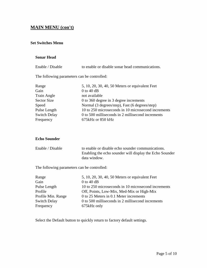
Set Switches Menu
Sonar Head
Enable / Disable to enable or disable sonar head communications.
The following parameters can be controlled:
Range 5, 10, 20, 30, 40, 50 Meters or equivalent Feet
Gain 0 to 40 dB
Train Angle not available
Sector Size 0 to 360 degree in 3 degree increments
Speed Normal (3 degrees/step), Fast (6 degrees/step)
Pulse Length 10 to 250 microseconds in 10 microsecond increments
Switch Delay 0 to 500 milliseconds in 2 millisecond increments
Frequency 675kHz or 850 kHz
Echo Sounder
Enable / Disable to enable or disable echo sounder communications.
Enabling the echo sounder will display the Echo Sounder
data window.
The following parameters can be controlled:
Range 5, 10, 20, 30, 40, 50 Meters or equivalent Feet
Gain 0 to 40 dB
Pulse Length 10 to 250 microseconds in 10 microsecond increments
Profile Off, Points, Low-Mix, Med-Mix or High-Mix
Profile Min. Range 0 to 25 Meters in 0.1 Meter increments
Switch Delay 0 to 500 milliseconds in 2 millisecond increments
Frequency 675kHz only
Select the Default button to quickly return to factory default settings.
Page 6 of 10
MAIN MENU (con't)
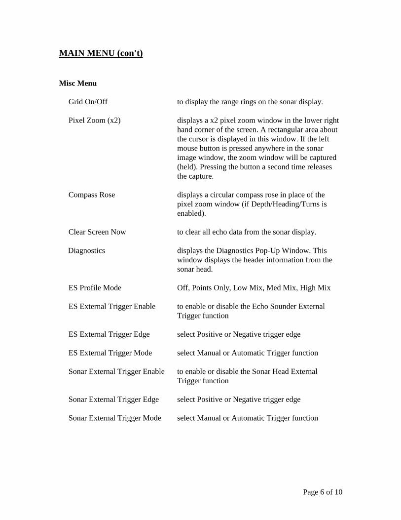
Misc Menu
Grid On/Off to display the range rings on the sonar display.
Pixel Zoom (x2) displays a x2 pixel zoom window in the lower right
hand corner of the screen. A rectangular area about
the cursor is displayed in this window. If the left
mouse button is pressed anywhere in the sonar
image window, the zoom window will be captured
(held). Pressing the button a second time releases
the capture.
Compass Rose displays a circular compass rose in place of the
pixel zoom window (if Depth/Heading/Turns is
enabled).
Clear Screen Now to clear all echo data from the sonar display.
Diagnostics displays the Diagnostics Pop-Up Window. This
window displays the header information from the
sonar head.
ES Profile Mode Off, Points Only, Low Mix, Med Mix, High Mix
ES External Trigger Enable to enable or disable the Echo Sounder External
Trigger function
ES External Trigger Edge select Positive or Negative trigger edge
ES External Trigger Mode select Manual or Automatic Trigger function
Sonar External Trigger Enable to enable or disable the Sonar Head External
Trigger function
Sonar External Trigger Edge select Positive or Negative trigger edge
Sonar External Trigger Mode select Manual or Automatic Trigger function
Page 7 of 10
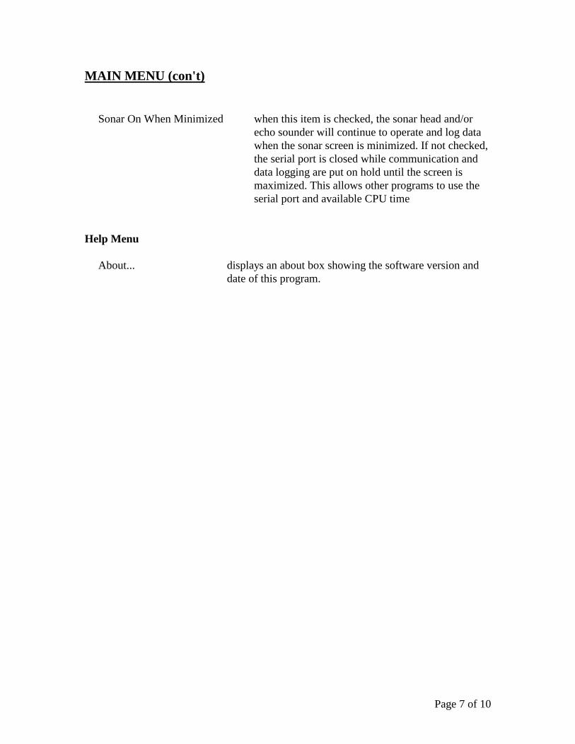
MAIN MENU (con't)
Sonar On When Minimized when this item is checked, the sonar head and/or
echo sounder will continue to operate and log data
when the sonar screen is minimized. If not checked,
the serial port is closed while communication and
data logging are put on hold until the screen is
maximized. This allows other programs to use the
serial port and available CPU time
Help Menu
About... displays an about box showing the software version and
date of this program.
Page 8 of 10
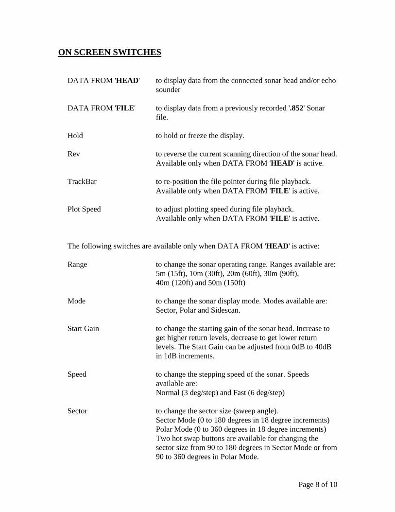
ON SCREEN SWITCHES
DATA FROM 'HEAD' to display data from the connected sonar head and/or echo
sounder
DATA FROM 'FILE' to display data from a previously recorded '.852' Sonar
file.
Hold to hold or freeze the display.
Rev to reverse the current scanning direction of the sonar head.
Available only when DATA FROM 'HEAD' is active.
TrackBar to re-position the file pointer during file playback.
Available only when DATA FROM 'FILE' is active.
Plot Speed to adjust plotting speed during file playback.
Available only when DATA FROM 'FILE' is active.
The following switches are available only when DATA FROM 'HEAD' is active:
Range to change the sonar operating range. Ranges available are:
5m (15ft), 10m (30ft), 20m (60ft), 30m (90ft),
40m (120ft) and 50m (150ft)
Mode to change the sonar display mode. Modes available are:
Sector, Polar and Sidescan.
Start Gain to change the starting gain of the sonar head. Increase to
get higher return levels, decrease to get lower return
levels. The Start Gain can be adjusted from 0dB to 40dB
in 1dB increments.
Speed to change the stepping speed of the sonar. Speeds
available are:
Normal (3 deg/step) and Fast (6 deg/step)
Sector to change the sector size (sweep angle).
Sector Mode (0 to 180 degrees in 18 degree increments)
Polar Mode (0 to 360 degrees in 18 degree increments)
Two hot swap buttons are available for changing the
sector size from 90 to 180 degrees in Sector Mode or from
90 to 360 degrees in Polar Mode.
Page 9 of 10
ON SCREEN SWITCHES (con’t)
Train always 0 degrees in Sector and Polar Modes.
Up, Down, Port and Stbd settings are available for
Sidescan Mode.
KEYBOARD SWITCHES
The following switches are selected via keyboard entry (case insensitive):
C to clear the sonar screen display.
G to change the Start Gain of the sonar head. When the 'G'
key is pressed, the Key Command Entry Box displays the
prompt: Gain: ? dB. Type in a valid start gain number (0-
40dB) and press <Enter> to change to the new start gain
value. If the entered gain is not valid or the <Esc> key is
pressed, the current gain will be used. Available only
when DATA FROM 'HEAD' is active.
H to hold or freeze the display.
R to change the operating range of the sonar head. When the
'R' key is pressed, the Key Command Entry Box (below
the DATA FROM buttons) is displayed with the
following prompt: Range: ? M (meters) or Range: ? FT
(feet). Type in a valid range number: 5(15), 10(30),
20(60), 30(90), 40(120) or 50(150) in meters or (feet)
using the numeric keys and then press <Enter> to change
to the new range. If the entered range is not valid or the
<Esc> key is pressed, the current range will be used.
Available only when DATA FROM 'HEAD' is active.
Space Bar to reverse the current sonar head scanning direction. Can
also be used to reverse the file playback direction.
Page 10 of 10
ONE CURSOR MEASUREMENT
One Cursor Measurement is used for measuring the distance and relative bearing to a
target with respect to the transducer origin. When the mouse is moved into the sonar
image display area, the cursor changes from an arrow to a square target cursor. The range
and bearing to the target cursor is displayed in the Range/Bearing Display Box
underneath the sonar image display. If a compass heading is present at the second serial
port, the displayed cursor bearing will include the copmpass heading. The area about the
target cursor is also displayed in the Pixel Zoom window. Clicking the left mouse button
while the cursor is in the sonar image display area captures (freezes) the zoom window
image. Clicking the left button a second time allows normal zoom window updating.
TWO CURSOR MEASUREMENT
Two Cursor Measurement is used for measuring the distance and relative bearing
between two targets. To invoke two cursor measurement, position the mouse cursor over
a target in the sonar image display area and press the right mouse button. A target origin
cursor is placed at this location. When the mouse is moved, a rubber banded line is drawn
from the target origin cursor to the target cursor. The Range/Bearing Display Box shows
the range and bearing from the transducer origin to the target cursor (Tar) and the range
and bearing difference (Diff) between the two cursors. If a compass heading is present at
the second serial port, the displayed cursor bearing will include the copmpass heading.
The displayed range and bearing between the two cursors is always relative to the target
origin cursor. Press the right mouse button again to return to One Cursor Measurement.
MESSAGES
No Data at COM? - no power to the sonar head and/or echo sounder
- cable not connected
- Sonar Head COM port set to the wrong port number
- computer not fast enough to keep up with the head
increase Switch Delay.
Depth ‘n/a’
Heading ‘n/a’
Turns Counter ‘n/a’ - ROV computer not connected to serial port
- ROV computer is not sending data
- ROV computer not set for 38400,N,8,1
- Depth/Heading/Turns COM port set to the wrong
port number
- ROV computer not sending correct ASCII string
Page 1 of 5
IMAGENEX TECHNOLOGY CORP. 16SEP15
MODEL 852 DIGITAL SONAR HEAD
MODEL 852 DIGITAL ECHO SOUNDER
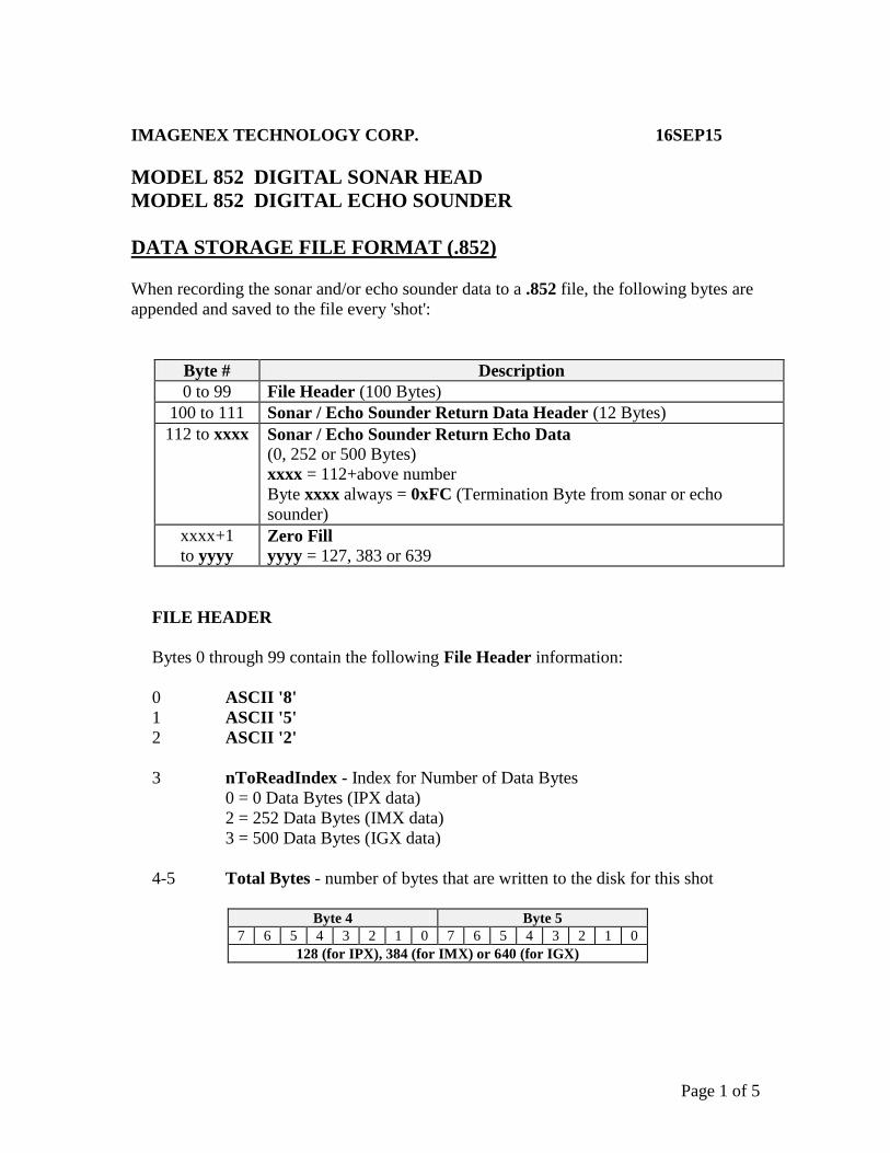
DATA STORAGE FILE FORMAT (.852)
When recording the sonar and/or echo sounder data to a .852 file, the following bytes are
appended and saved to the file every 'shot':
Byte # Description
0 to 99 File Header (100 Bytes)
100 to 111 Sonar / Echo Sounder Return Data Header (12 Bytes)
112 to xxxx Sonar / Echo Sounder Return Echo Data
(0, 252 or 500 Bytes)
xxxx = 112+above number
Byte xxxx always = 0xFC (Termination Byte from sonar or echo
sounder)
xxxx+1
to yyyy Zero Fill
yyyy = 127, 383 or 639
FILE HEADER
Bytes 0 through 99 contain the following File Header information:
0 ASCII '8'
1 ASCII '5'
2 ASCII '2'
3 nToReadIndex - Index for Number of Data Bytes
0 = 0 Data Bytes (IPX data)
2 = 252 Data Bytes (IMX data)
3 = 500 Data Bytes (IGX data)
4-5 Total Bytes - number of bytes that are written to the disk for this shot
Byte 4 Byte 5
7 6 5 4 3 2 1 0 7 6 5 4 3 2 1 0
128 (for IPX), 384 (for IMX) or 640 (for IGX)

Page 2 of 5
DATA STORAGE FILE FORMAT (.852) (con't)
6-7 nToRead - Number of Bytes from the sonar or echo sounder
Byte 6 Byte 7
7 6 5 4 3 2 1 0 7 6 5 4 3 2 1 0
13 (for IPX), 265 (for IMX) or 513 (for IGX)
8-19 Date - null terminated date string (12 bytes)
"DD-MMM-YYYY"
20-28 Time - null terminated time string (9 bytes)
"HH:MM:SS"
29-32 Hundredth of Seconds - null terminated string (4 bytes)
".hh"
33-36 Reserved – always 0
37 Dir, Xdcr, Mode, Step
For Sonar Head (Head ID = 0x10): Byte 37
7 6 5 4 3 2 1 0
Dir Xdcr Mode Step Size
0=ccw
1=cw
0=Dn
1=Up
0 = Sector (IGX)
1 = Polar (IMX)
0 = 2.25 Deg (Slow)
1 = 4.5 Deg (Fast)
For Echo Sounder (Head ID = 0x11): Byte 37
7 6 5 4 3 2 1 0
N/A N/A Mode N/A
0 0 0 = IGX
1 = IMX
0
38 Start Gain
0 to 40 in 1 dB increments
39 (Sector Size)/3
For Sonar Head (Head ID = 0x10):
0 to 102 = 0 to 306 Degrees in 3 degree increments
For Echo Sounder (Head ID = 0x11):
Reserved – always 0
Page 3 of 5
DATA STORAGE FILE FORMAT (.852) (con't)
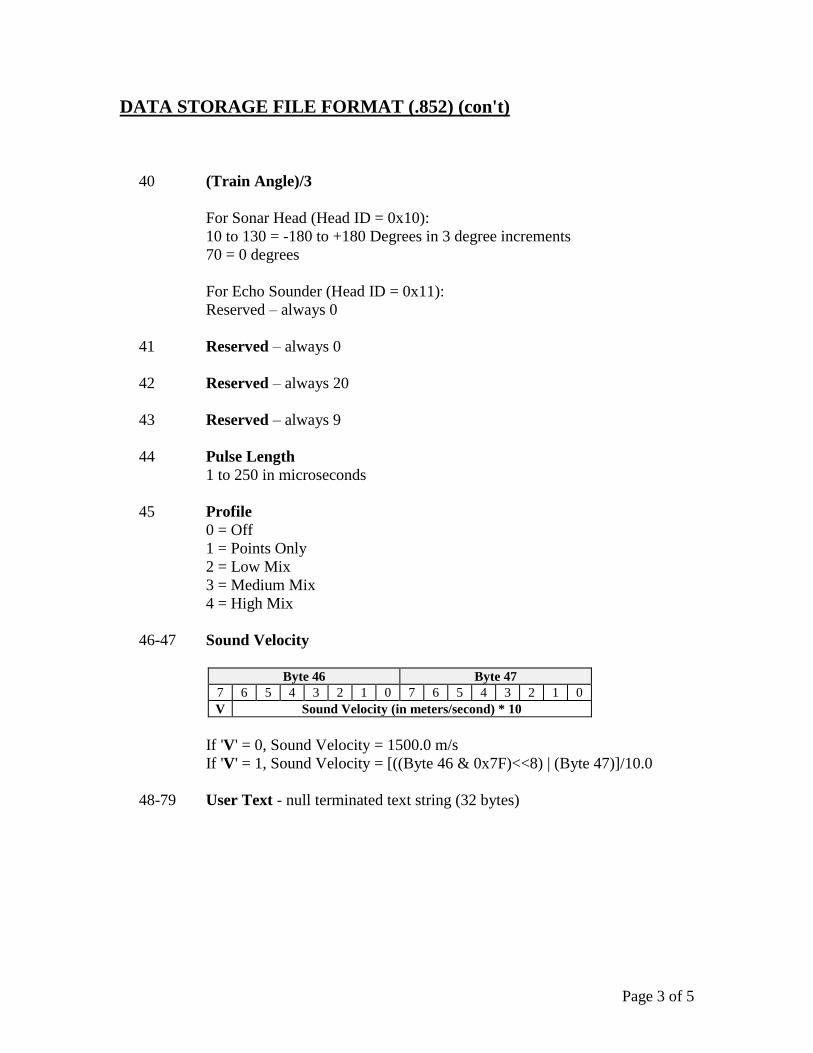
40 (Train Angle)/3
For Sonar Head (Head ID = 0x10):
10 to 130 = -180 to +180 Degrees in 3 degree increments
70 = 0 degrees
For Echo Sounder (Head ID = 0x11):
Reserved – always 0
41 Reserved – always 0
42 Reserved – always 20
43 Reserved – always 9
44 Pulse Length
1 to 250 in microseconds
45 Profile
0 = Off
1 = Points Only
2 = Low Mix
3 = Medium Mix
4 = High Mix
46-47 Sound Velocity
Byte 46 Byte 47
7 6 5 4 3 2 1 0 7 6 5 4 3 2 1 0
V Sound Velocity (in meters/second) * 10
If 'V' = 0, Sound Velocity = 1500.0 m/s
If 'V' = 1, Sound Velocity = [((Byte 46 & 0x7F)<<8) | (Byte 47)]/10.0
48-79 User Text - null terminated text string (32 bytes)
Page 4 of 5
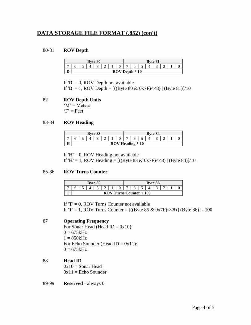
DATA STORAGE FILE FORMAT (.852) (con't)
80-81 ROV Depth
Byte 80 Byte 81
7 6 5 4 3 2 1 0 7 6 5 4 3 2 1 0
D ROV Depth * 10
If 'D' = 0, ROV Depth not available
If 'D' = 1, ROV Depth = [((Byte 80 & 0x7F)<<8) | (Byte 81)]/10
82 ROV Depth Units ‘M’ = Meters
‘F’ = Feet
83-84 ROV Heading
Byte 83 Byte 84
7 6 5 4 3 2 1 0 7 6 5 4 3 2 1 0
H ROV Heading * 10
If 'H' = 0, ROV Heading not available
If 'H' = 1, ROV Heading = [((Byte 83 & 0x7F)<<8) | (Byte 84)]/10
85-86 ROV Turns Counter
Byte 85 Byte 86
7 6 5 4 3 2 1 0 7 6 5 4 3 2 1 0
T ROV Turns Counter + 100
If 'T' = 0, ROV Turns Counter not available
If 'T' = 1, ROV Turns Counter = [((Byte 85 & 0x7F)<<8) | (Byte 86)] - 100
87 Operating Frequency
For Sonar Head (Head ID = 0x10):
0 = 675kHz
1 = 850kHz
For Echo Sounder (Head ID = 0x11):
0 = 675kHz
88 Head ID
0x10 = Sonar Head
0x11 = Echo Sounder
89-99 Reserved - always 0
Page 5 of 5
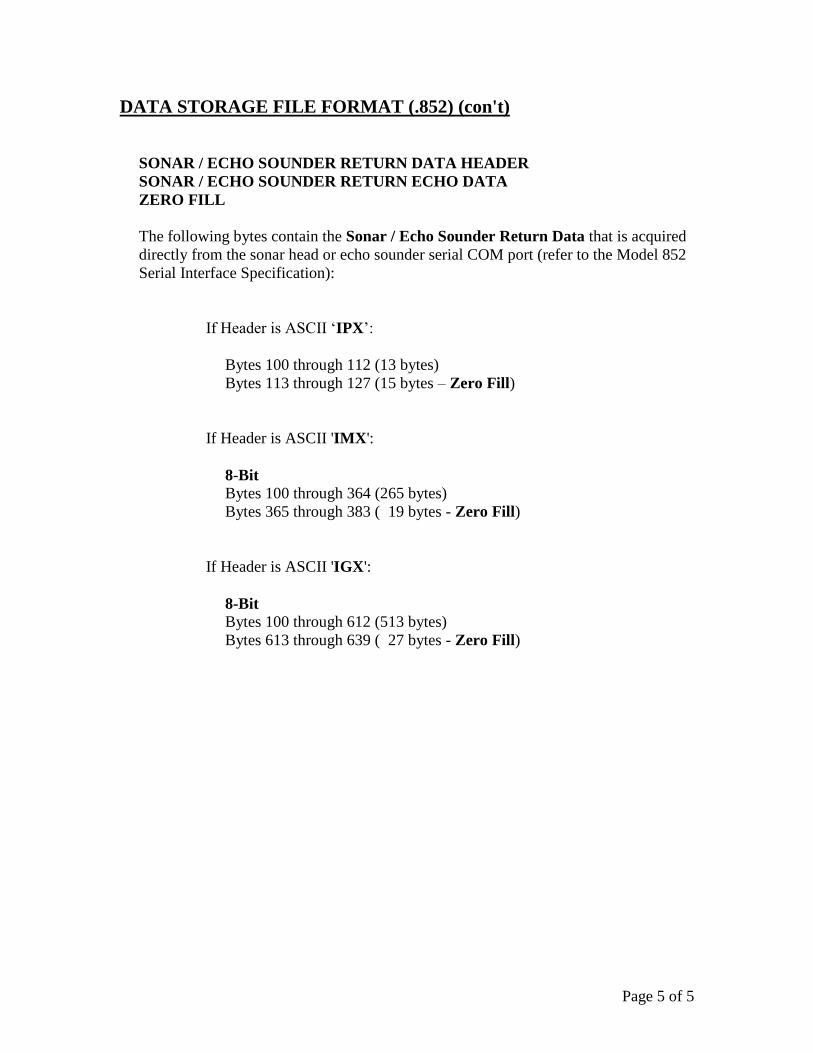
DATA STORAGE FILE FORMAT (.852) (con't)
SONAR / ECHO SOUNDER RETURN DATA HEADER
SONAR / ECHO SOUNDER RETURN ECHO DATA
ZERO FILL
The following bytes contain the Sonar / Echo Sounder Return Data that is acquired
directly from the sonar head or echo sounder serial COM port (refer to the Model 852
Serial Interface Specification):
If Header is ASCII ‘IPX’:
Bytes 100 through 112 (13 bytes)
Bytes 113 through 127 (15 bytes – Zero Fill)
If Header is ASCII 'IMX':
8-Bit Bytes 100 through 364 (265 bytes)
Bytes 365 through 383 ( 19 bytes - Zero Fill)
If Header is ASCII 'IGX':
8-Bit Bytes 100 through 612 (513 bytes)
Bytes 613 through 639 ( 27 bytes - Zero Fill)
Page 1 of 8
IMAGENEX TECHNOLOGY CORP. 05FEB16
MODEL 852 DIGITAL ECHO SOUNDER
SERIAL INTERFACE SPECIFICATION (v1.04)
OVERVIEW
The Model 852 Digital Echo Sounder communicates over a 2-wire differential RS-485
serial data transmission line or optionally a half-duplex RS-232 data line. To interrogate
the echo sounder and receive echo data, a Switch Data Command string is sent via a serial
command program at a baud rate of 115200 bps, No Parity, 8 Data Bits and 1 Stop Bit.
When the Switch Data command is accepted, the echo sounder transmits, receives and
sends its return data back to the commanding program.
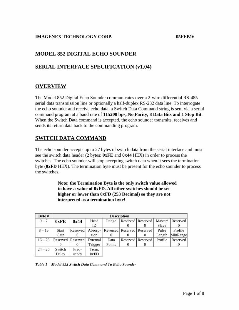
SWITCH DATA COMMAND
The echo sounder accepts up to 27 bytes of switch data from the serial interface and must
see the switch data header (2 bytes: 0xFE and 0x44 HEX) in order to process the
switches. The echo sounder will stop accepting switch data when it sees the termination
byte (0xFD HEX). The termination byte must be present for the echo sounder to process
the switches.
Note: the Termination Byte is the only switch value allowed
to have a value of 0xFD. All other switches should be set
higher or lower than 0xFD (253 Decimal) so they are not
interpreted as a termination byte!
Byte # Description
0 – 7 0xFE 0x44 Head
ID
Range Reserved
0
Reserved
0
Master/
Slave
Reserved
0
8 – 15 Start
Gain
Reserved
0
Absorp-
tion
Reversed
0
Reserved
0
Reserved
0
Pulse
Length
Profile
MinRange
16 – 23 Reserved
0
Reserved
0
External
Trigger
Data
Points
Reserved
0
Reserved
0
Profile Reserved
0
24 – 26 Switch
Delay
Freq-
uency
Term.
0xFD
Table 1 Model 852 Switch Data Command To Echo Sounder

Page 2 of 8
SWITCH DATA COMMAND (con't)
BYTE DESCRIPTIONS
Note: All Byte values are shown in decimal unless noted with a '0x' (hexadecimal) prefix.
Byte 0 Switch Data Header (1st Byte)
Always 0xFE (254 decimal)
Byte 1 Switch Data Header (2nd Byte)
Always 0x44 (68 decimal)
Byte 2 Head ID
0x11, 0x12, 0x13, 0x14 or 0x15
Byte 3 Range
5 to 50 Meters
5,10,20,30,40,50 Meters supported
Byte 4 Reserved
Always 0
Byte 5 Reserved
Always 0
Byte 6 Master / Slave
The echo sounder can be operated as a master or as a slave. The default
mode on power-up is Slave mode (Bit 6 = 1). Slave mode allows the user
to command the unit to transmit then send its return data at any given time.
Currently, the echo sounder only supports slave mode operation.
Bit 0 - 1 = Transmit if Bit 6 = 1 (Slave Mode)
Bit 1 - 1 = Send Data if Bit 6 = 1 (Slave Mode)
Bit 2 - 0
Bit 3 - 0
Bit 4 - 0
Bit 5 - 0
Bit 6 - 0 = Master, 1 = Slave
Bit 7 - 0
Byte 7 Reserved
Always 0
Page 3 of 8
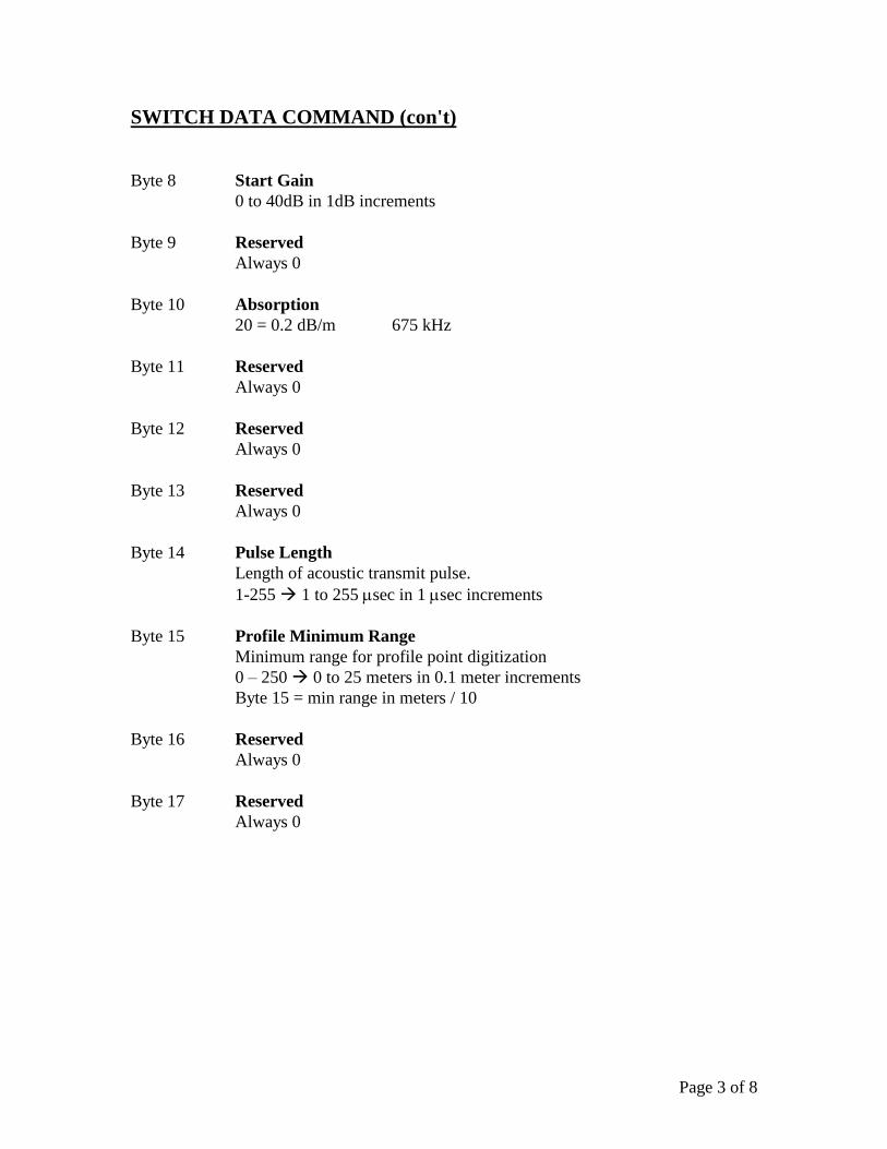
SWITCH DATA COMMAND (con't)
Byte 8 Start Gain
0 to 40dB in 1dB increments
Byte 9 Reserved
Always 0
Byte 10 Absorption
20 = 0.2 dB/m 675 kHz
Byte 11 Reserved
Always 0
Byte 12 Reserved
Always 0
Byte 13 Reserved
Always 0
Byte 14 Pulse Length
Length of acoustic transmit pulse.
1-255 1 to 255 sec in 1 sec increments
Byte 15 Profile Minimum Range
Minimum range for profile point digitization
0 – 250 0 to 25 meters in 0.1 meter increments
Byte 15 = min range in meters / 10
Byte 16 Reserved
Always 0
Byte 17 Reserved
Always 0
Page 4 of 8
SWITCH DATA COMMAND (con't)
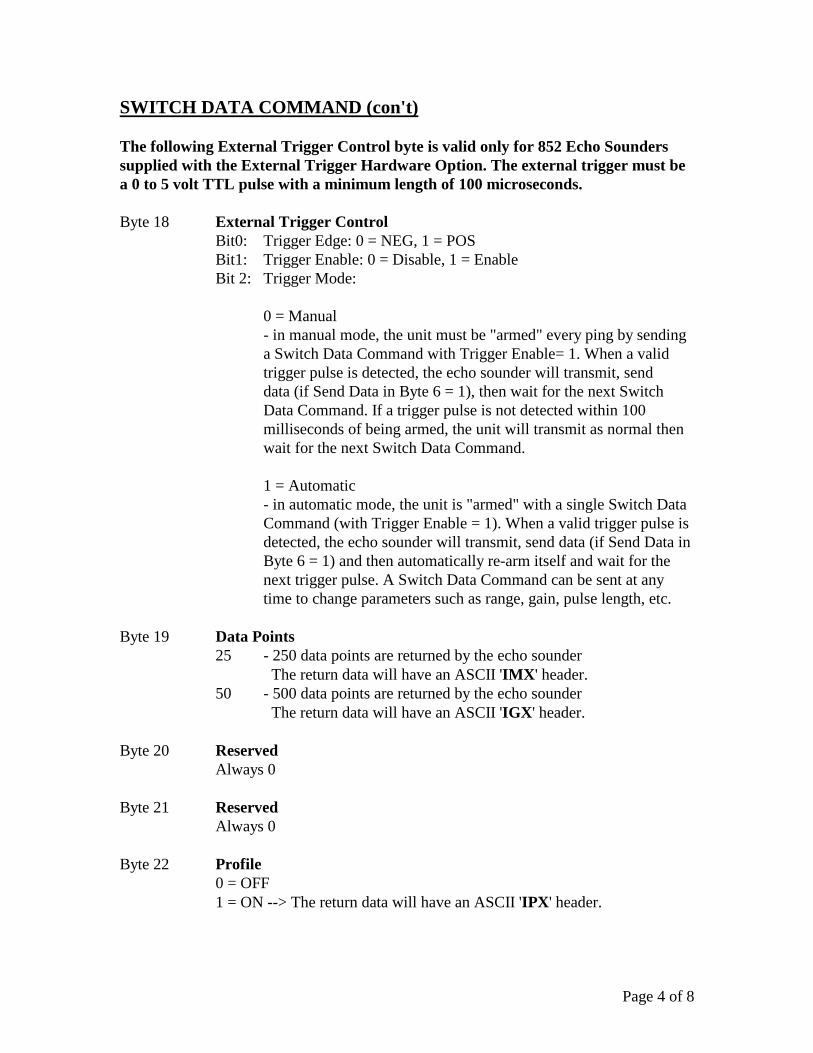
The following External Trigger Control byte is valid only for 852 Echo Sounders
supplied with the External Trigger Hardware Option. The external trigger must be
a 0 to 5 volt TTL pulse with a minimum length of 100 microseconds.
Byte 18 External Trigger Control
Bit0: Trigger Edge: 0 = NEG, 1 = POS
Bit1: Trigger Enable: 0 = Disable, 1 = Enable
Bit 2: Trigger Mode:
0 = Manual
- in manual mode, the unit must be "armed" every ping by sending
a Switch Data Command with Trigger Enable= 1. When a valid
trigger pulse is detected, the echo sounder will transmit, send
data (if Send Data in Byte 6 = 1), then wait for the next Switch
Data Command. If a trigger pulse is not detected within 100
milliseconds of being armed, the unit will transmit as normal then
wait for the next Switch Data Command.
1 = Automatic
- in automatic mode, the unit is "armed" with a single Switch Data
Command (with Trigger Enable = 1). When a valid trigger pulse is
detected, the echo sounder will transmit, send data (if Send Data in
Byte 6 = 1) and then automatically re-arm itself and wait for the
next trigger pulse. A Switch Data Command can be sent at any
time to change parameters such as range, gain, pulse length, etc.
Byte 19 Data Points
25 - 250 data points are returned by the echo sounder
The return data will have an ASCII 'IMX' header.
50 - 500 data points are returned by the echo sounder
The return data will have an ASCII 'IGX' header.
Byte 20 Reserved
Always 0
Byte 21 Reserved
Always 0
Byte 22 Profile
0 = OFF
1 = ON --> The return data will have an ASCII 'IPX' header.
Page 5 of 8
SWITCH DATA COMMAND (con't)
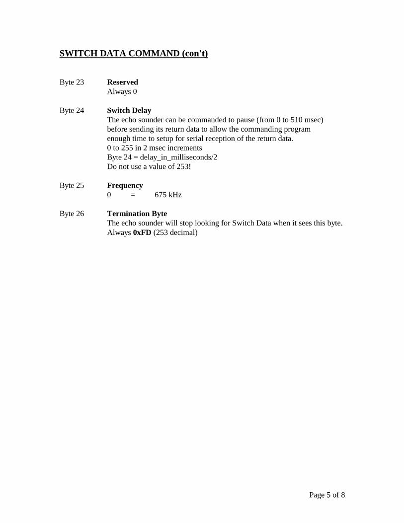
Byte 23 Reserved
Always 0
Byte 24 Switch Delay
The echo sounder can be commanded to pause (from 0 to 510 msec)
before sending its return data to allow the commanding program
enough time to setup for serial reception of the return data.
0 to 255 in 2 msec increments
Byte 24 = delay_in_milliseconds/2
Do not use a value of 253!
Byte 25 Frequency
0 = 675 kHz
Byte 26 Termination Byte
The echo sounder will stop looking for Switch Data when it sees this byte.
Always 0xFD (253 decimal)
Page 6 of 8
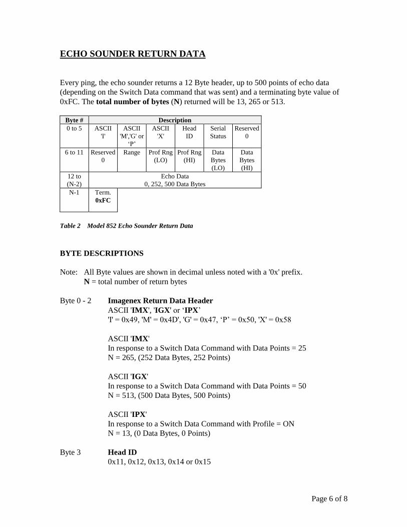
ECHO SOUNDER RETURN DATA
Every ping, the echo sounder returns a 12 Byte header, up to 500 points of echo data
(depending on the Switch Data command that was sent) and a terminating byte value of
0xFC. The total number of bytes (N) returned will be 13, 265 or 513.
Byte # Description
0 to 5 ASCII
'I'
ASCII
'M','G' or
‘P’
ASCII
'X'
Head
ID
Serial
Status
Reserved
0
6 to 11 Reserved
0
Range Prof Rng
(LO)
Prof Rng
(HI)
Data
Bytes
(LO)
Data
Bytes
(HI)
12 to
(N-2)
Echo Data
0, 252, 500 Data Bytes
N-1 Term.
0xFC
Table 2 Model 852 Echo Sounder Return Data
BYTE DESCRIPTIONS
Note: All Byte values are shown in decimal unless noted with a '0x' prefix.
N = total number of return bytes
Byte 0 - 2 Imagenex Return Data Header
ASCII 'IMX', 'IGX' or ‘IPX’
'I' = 0x49, 'M' = 0x4D', 'G' = 0x47, ‘P’ = 0x50, 'X' = 0x58
ASCII 'IMX'
In response to a Switch Data Command with Data Points = 25
N = 265, (252 Data Bytes, 252 Points)
ASCII 'IGX'
In response to a Switch Data Command with Data Points = 50
N = 513, (500 Data Bytes, 500 Points)
ASCII 'IPX'
In response to a Switch Data Command with Profile = ON
N = 13, (0 Data Bytes, 0 Points)
Byte 3 Head ID
0x11, 0x12, 0x13, 0x14 or 0x15
Page 7 of 8
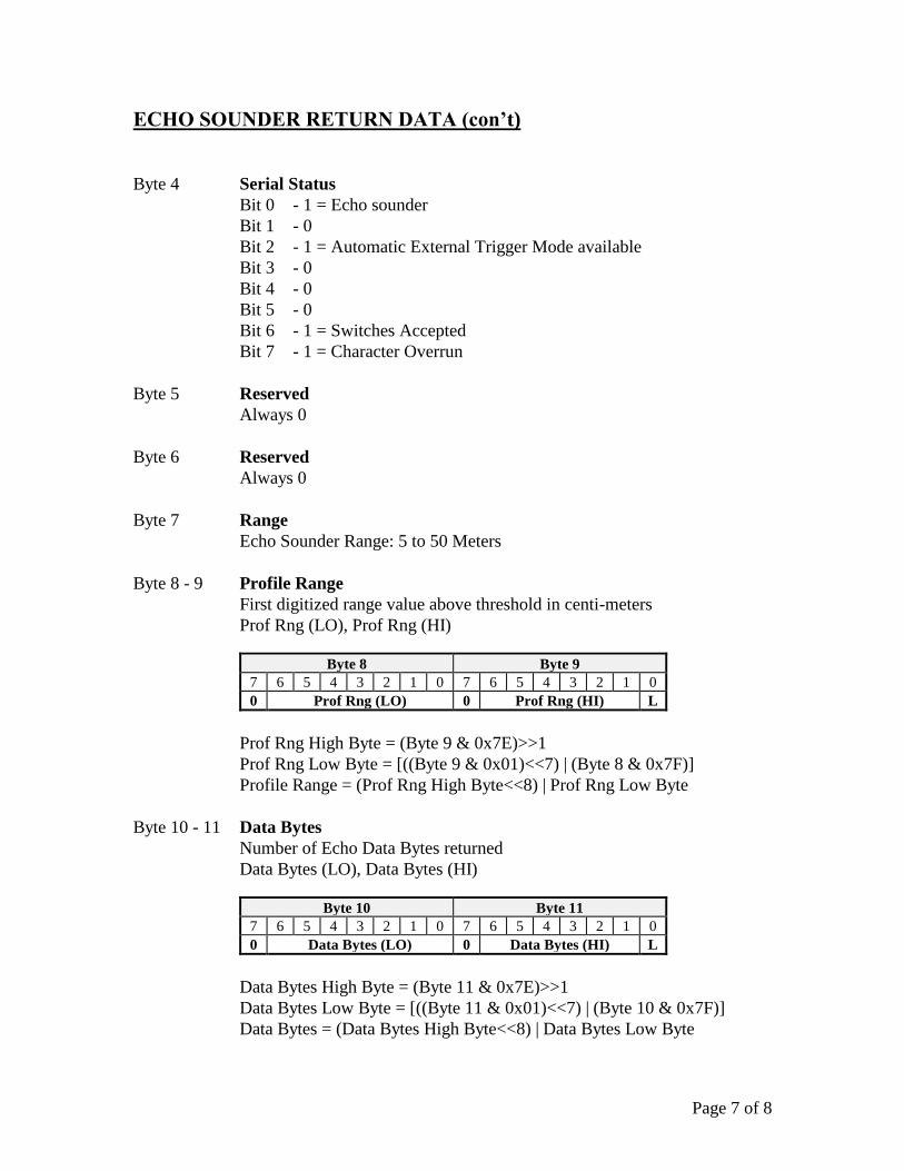
ECHO SOUNDER RETURN DATA (con’t)
Byte 4 Serial Status
Bit 0 - 1 = Echo sounder
Bit 1 - 0
Bit 2 - 1 = Automatic External Trigger Mode available
Bit 3 - 0
Bit 4 - 0
Bit 5 - 0
Bit 6 - 1 = Switches Accepted
Bit 7 - 1 = Character Overrun
Byte 5 Reserved
Always 0
Byte 6 Reserved
Always 0
Byte 7 Range
Echo Sounder Range: 5 to 50 Meters
Byte 8 - 9 Profile Range
First digitized range value above threshold in centi-meters
Prof Rng (LO), Prof Rng (HI)
Byte 8 Byte 9
7 6 5 4 3 2 1 0 7 6 5 4 3 2 1 0
0 Prof Rng (LO) 0 Prof Rng (HI) L
Prof Rng High Byte = (Byte 9 & 0x7E)>>1
Prof Rng Low Byte = [((Byte 9 & 0x01)<<7) | (Byte 8 & 0x7F)]
Profile Range = (Prof Rng High Byte<<8) | Prof Rng Low Byte
Byte 10 - 11 Data Bytes
Number of Echo Data Bytes returned
Data Bytes (LO), Data Bytes (HI)
Byte 10 Byte 11
7 6 5 4 3 2 1 0 7 6 5 4 3 2 1 0
0 Data Bytes (LO) 0 Data Bytes (HI) L
Data Bytes High Byte = (Byte 11 & 0x7E)>>1
Data Bytes Low Byte = [((Byte 11 & 0x01)<<7) | (Byte 10 & 0x7F)]
Data Bytes = (Data Bytes High Byte<<8) | Data Bytes Low Byte
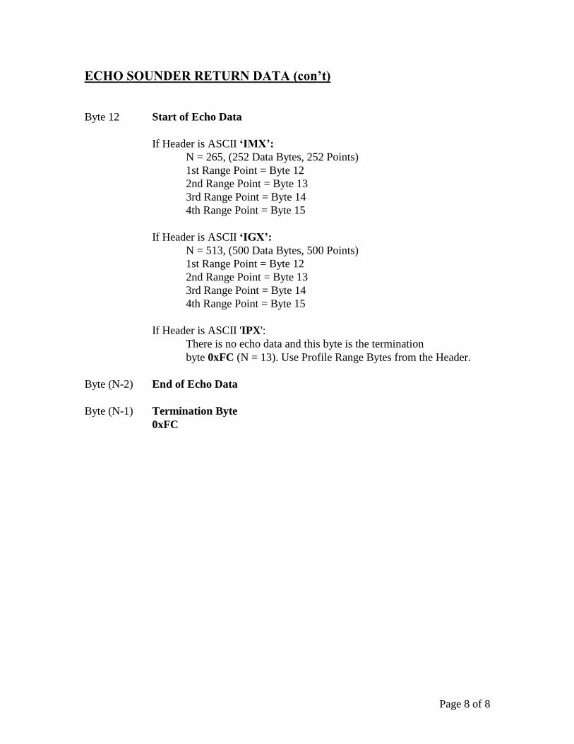
Page 8 of 8
ECHO SOUNDER RETURN DATA (con’t)
Byte 12 Start of Echo Data
If Header is ASCII ‘IMX’:
N = 265, (252 Data Bytes, 252 Points)
1st Range Point = Byte 12
2nd Range Point = Byte 13
3rd Range Point = Byte 14
4th Range Point = Byte 15
If Header is ASCII ‘IGX’:
N = 513, (500 Data Bytes, 500 Points)
1st Range Point = Byte 12
2nd Range Point = Byte 13
3rd Range Point = Byte 14
4th Range Point = Byte 15
If Header is ASCII 'IPX':
There is no echo data and this byte is the termination
byte 0xFC (N = 13). Use Profile Range Bytes from the Header.
Byte (N-2) End of Echo Data
Byte (N-1) Termination Byte
0xFC
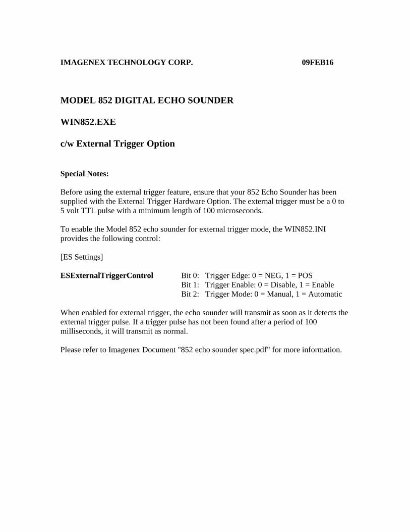
IMAGENEX TECHNOLOGY CORP. 09FEB16
MODEL 852 DIGITAL ECHO SOUNDER
WIN852.EXE
c/w External Trigger Option
Special Notes:
Before using the external trigger feature, ensure that your 852 Echo Sounder has been
supplied with the External Trigger Hardware Option. The external trigger must be a 0 to
5 volt TTL pulse with a minimum length of 100 microseconds.
To enable the Model 852 echo sounder for external trigger mode, the WIN852.INI
provides the following control:
[ES Settings]
ESExternalTriggerControl Bit 0: Trigger Edge: 0 = NEG, 1 = POS
Bit 1: Trigger Enable: 0 = Disable, 1 = Enable
Bit 2: Trigger Mode: 0 = Manual, 1 = Automatic
When enabled for external trigger, the echo sounder will transmit as soon as it detects the
external trigger pulse. If a trigger pulse has not been found after a period of 100
milliseconds, it will transmit as normal.
Please refer to Imagenex Document "852 echo sounder spec.pdf" for more information.
SONAR THEORY AND APPLICATIONS
EXCERPT FROM IMAGENEX MODEL 855
COLOR IMAGING SONAR USER'S MANUAL
IMAGENEX TECHNOLOGY CORP.#209 - 1875 BROADWAY ST.
PORT COQUITLAM, B.C. V3C 4Z1CANADA
TEL: (604) 944-8248FAX: (604) 944-8249
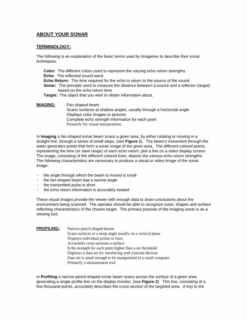
ABOUT YOUR SONAR
TERMINOLOGY:
The following is an explanation of the basic terms used by Imagenex to describe their sonartechniques.
Color: The different colors used to represent the varying echo return strengths.Echo: The reflected sound waveEcho Return: The time required for the echo to return to the source of the soundSonar: The principle used to measure the distance between a source and a reflector (target)
based on the echo return timeTarget: The object that you wish to obtain information about.
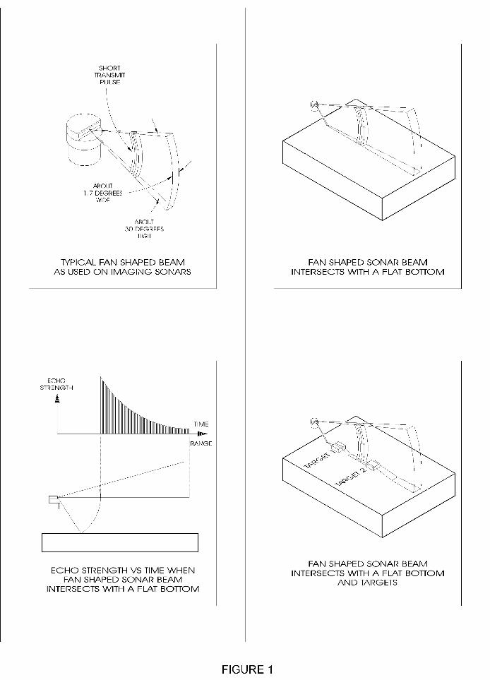
IMAGING: Fan shaped beamScans surfaces at shallow angles, usually through a horizontal angleDisplays color images or picturesComplete echo strength information for each pointPrimarily for visual interpretation
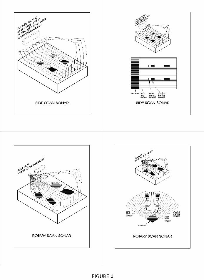
In Imaging a fan-shaped sonar beam scans a given area, by either rotating or moving in astraight line, through a series of small steps, (see Figure 1). The beam's movement through thewater generates points that form a sonar image of the given area. The different colored points,representing the time (or slant range) of each echo return, plot a line on a video display screen.The image, consisting of the different colored lines, depicts the various echo return strengths.The following characteristics are necessary to produce a visual or video image of the sonarimage:
! the angle through which the beam is moved is small! the fan-shaped beam has a narrow angle! the transmitted pulse is short! the echo return information is accurately treated
These visual images provide the viewer with enough data to draw conclusions about theenvironment being scanned. The operator should be able to recognize sizes, shapes and surfacereflecting characteristics of the chosen target. The primary purpose of the imaging sonar is as aviewing tool.
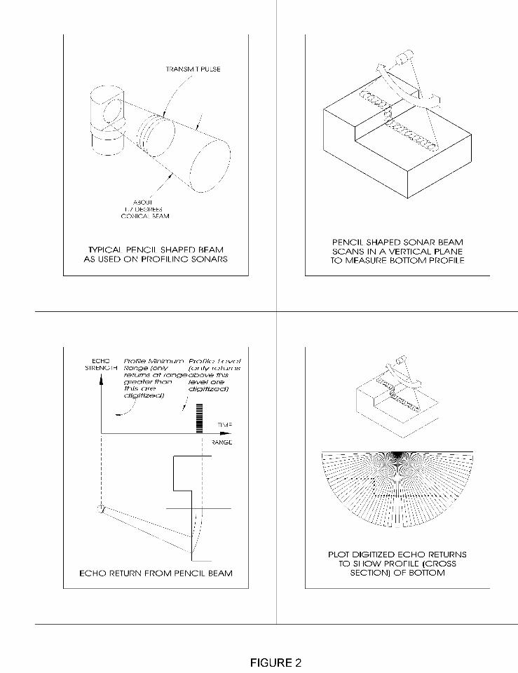
PROFILING: Narrow pencil shaped beamsScans surfaces at a steep angle usually on a vertical planeDisplays individual points or linesAccurately cross-sections a surfaceEcho strength for each point higher than a set thresholdDigitizes a data set for interfacing with external devicesData set is small enough to be manipulated in a small computerPrimarily a measurement tool
In Profiling a narrow pencil-shaped sonar beam scans across the surface of a given areagenerating a single profile line on the display monitor, (see Figure 2). This line, consisting of afew thousand points, accurately describes the cross-section of the targeted area. A key to the
Profiling process is the selection of the echo returns for plotting. The sonar selects the echoreturns, typically one or two returns for each "shot", based on a given criterion for the echo returnstrength and the minimum profiling range. The information gathered from the selection criteriaforms a data set containing the range and bearing figures. An external device, such as apersonal computer or data logger, accesses the data set through an RS-232 interface with thesonar.
The profile data is useful for making pen plots of bottom profiles, trench profiles, internal andexternal pipeline profiles. The primary purpose of the profiling sonar is as a quantitativemeasuring tool.
USING AN IMAGING SONAR ON AN ROV
The imaging sonar is a useful substitute for a positioning system on an ROV. Without an imagingsonar, an ROV relies on traveling underwater to bring new targets into view. With an imagingsonar, instead of traveling it is more useful to spend some time with the vehicle sitting on thebottom while the sonar scans the surrounding area. Scanning a large area takes only a shorttime, and the vehicle pilot can quickly assess the nature of the surrounding area. The ability to"see" a long distance underwater allows the pilot to use natural or man-made features and targetsas position references.
The combination of an imaging sonar and an ROV leads to fast and effective training in sonarinterpretation. If the ROV pilot is searching for a particular object, recognition can take placedirectly from the sonar image. In other cases a number of potential targets may be seen. A pilotcan sharpen his sonar interpretation skills by viewing these targets with the vehicle's videocamera and correctly identify them.
INTERPRETATION OF SONAR IMAGES
In many cases the sonar image of a target will closely resemble an optical image of the sameobject. In other cases, the sonar image may be difficult to interpret and quite unlike the expectedoptical image. The scanning process used to create a sonar image is different from the processused by the human eye or a camera to produce optical images. A sonar image will always haveless resolution than an optical image, due to the nature of the ultrasonic signals used to generateit.
Generally, rough objects reflect sound well in many directions and are therefore good sonartargets. Smooth angular surfaces may give a very strong reflection in one particular direction, butalmost none at all in other directions. Some objects, such as smooth plane surfaces, may bedifficult to see with a sonar. They can act as a perfect mirror (so called specular reflectors),reflecting the sonar pulse off in unexpected directions, never to return. This happens to peoplevisually, when they see an object reflected in a window. The human eye deals with suchreflections daily but it is surprising to see the same thing occur with a sonar image. As withnormal vision, it is often useful to scan targets from different positions, to help identify them. Atarget which is unrecognizable from one direction may be quite easy to identify from another.
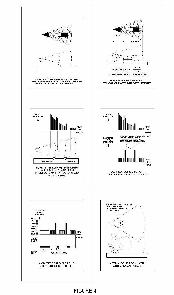
It is very important to note that the ranges shown to the targets on the sonar image are "slant"ranges. Usually the relative elevations of the targets are not known, only the range from thetransducer. This means that two targets, which are displayed in the same location on the screenmay be at different elevations. For example, you might see a target on the bottom, and a target

floating on the surface in the same place. By analyzing the shadows you can estimate the heightof objects above the bottom. An example of this calculation is shown in Figure 4.
The diagrams following this chapter are examples of the sonar scanning process. Studying thediagrams will help you to better understand the images that you see. A basic knowledge of thisprocess will help users to interpret what otherwise might be confusing images.