Image Enhancement Methods Approach using Verilog Hardware
5
11 th International Conference on DEVELOPMENT AND APPLICATION SYSTEMS, Suceava, Romania, May 17-19, 2012 144 Abstract — Given the importance of digital image processing based on hardware implementations in order to achieve higher performance, this paper discusses basic image enhancement techniques with their implementation and results using a hardware description language, Verilog. The use of HDLs to provide signal processing results is a quite new technique replacing the classical simulations and offering a direct connection to hardware VLSI implementations. This paper is providing an innovative method for simulation followed by immediate implementation possibility. The present HDL approach is applied to image processing and accordingly an overview of underlying principle and concepts, along with common algorithms usually used for image enhancement are described. The paper focuses on image enhancement in the spatial domain, with particular reference to point processing methods like: contrast manipulation, brightness manipulation, inverting images, threshold operation. Index Terms — Digital image processing, Image enhancement, FPGA, Hardware design languages, Verilog. I. INTRODUCTION The Hardware Description Languages (HDLs) larger availability allows the designers to not only logically describe circuit functionality but to simulate and evaluate the processing performances using appropriate development and test environments. While the simulation is generating the logical results a natural step consist in extending the use of the hardware simulators into the field of signal processing. The main advantage of using HDLs to simulate digital processing of any logical inputs is related with the possibility of an immediate FPGA based hardware implementation. Since the HDL syntax is always related to a hardware structure, the timing information of the potential hardware implementation is also available allowing specific speed optimizations. Out of that, the use of HDLs means hardware portability and on-the-fly re-programmability. The main challenge is to transpose the validated algorithms into a non-programming language as hardware description languages are. Also, the input and output data files need to be reshaped to match the binary content permitted into the hardware simulators. Interesting results are obtained in video processing as is presented in the paper. The digital image processing is impacted today in some way with a very large area of technical endeavor [1]. Digital image processing is used in very large and expanding areas covering applications in multimedia services, arts, medicine, space exploration, surveillance, authentication, automated industry inspection and many more areas [1]. The areas of application of digital image processing are quite heterogeneous. To capture the breadth of this field in order to develop a basic understanding of image processing applications means to categorize images according to their source, like electromagnetic energy spectrum (e.g., X-ray), acoustic, ultrasonic, and electronic, or synthetic images generated by computer [1]. These kind of applications involve different processes, including image quality enhancement and object detection. It is important to note that this kind of processing ask for appropriate resources, as memory availability or specific attached peripheral devices out of processing power needs. All these are not available on all ordinary general purpose computers and many times the related procedures are not very time efficient due to other additional constraints. Using application specific hardware as ASICs or FPGAs a much greater efficiency can be obtained compared with a software implementation. The VLSI (Very Large Scale Integrated) technology offers today complex alternative hardware implementation solutions [2]. The use of configurable hardware and system level programming languages allow direct implementation of image processing algorithms with improved performances and with a short time-to-market interval. There are many technologies available for hardware implementation. Application Specific Integrated Circuits (ASIC) and Field Programmable Gate Arrays (FPGA’s) are both reconfigurable devices able to support techniques such parallelism and pipelining. The use of reconfigurable hardware to implement algorithms for image processing minimizes the time-to- market cost while rapid prototyping with simplified debugging and verification stages is also possible. [3]. Therefore, the reconfigurable devices seem to be the ideal choice for implementation of image processing algorithms. Field Programmable Gate Arrays have traditionally been configured by hardware designers using specific so called Hardware Design Languages (HDLs). There are already few such languages available offering different levels of abstraction but the most important ones are Verilog HDL (Verilog) and Very High Speed Integrated Circuits (VHSIC) HDL (VHDL) [2]. II. IMAGE ENHANCEMENT METHODS One of the most spectacular and interesting image processing approaches is the image enhancement. The interest for this domain stems from two principal application directions: Image Enhancement Methods Approach using Verilog Hardware Description Language Iuliana CHIUCHISAN, Marius CERLINCA, Alin-Dan POTORAC, Adrian GRAUR "Stefan cel Mare" University of Suceava str.Universitatii nr.13, RO-720229 Suceava [email protected],[email protected],[email protected],[email protected]
Transcript of Image Enhancement Methods Approach using Verilog Hardware

11th International Conference on DEVELOPMENT AND APPLICATION SYSTEMS, Suceava, Romania, May 17-19, 2012
144
Abstract — Given the importance of digital image processingbased on hardware implementations in order to achieve higher performance, this paper discusses basic image enhancement techniques with their implementation and results using a hardware description language, Verilog. The use of HDLs to provide signal processing results is a quite new technique replacing the classical simulations and offering a direct connection to hardware VLSI implementations. This paper is providing an innovative method for simulation followed by immediate implementation possibility. The present HDL approach is applied to image processing and accordingly an overview of underlying principle and concepts, along with common algorithms usually used for image enhancement are described.The paper focuses on image enhancement in the spatial domain, with particular reference to point processing methodslike: contrast manipulation, brightness manipulation, inverting images, threshold operation.
Index Terms — Digital image processing, Image enhancement, FPGA, Hardware design languages, Verilog.
I. INTRODUCTION
The Hardware Description Languages (HDLs) larger availability allows the designers to not only logically describe circuit functionality but to simulate and evaluate the processing performances using appropriate development and test environments. While the simulation is generating the logical results a natural step consist in extending the use of the hardware simulators into the field of signal processing.
The main advantage of using HDLs to simulate digital processing of any logical inputs is related with the possibility of an immediate FPGA based hardware implementation. Since the HDL syntax is always related to a hardware structure, the timing information of the potential hardware implementation is also available allowing specific speed optimizations. Out of that, the use of HDLs means hardware portability and on-the-fly re-programmability. The main challenge is to transpose the validated algorithms into a non-programming language as hardware description languages are. Also, the input and output data files need to be reshaped to match the binary content permitted into the hardware simulators. Interesting results are obtained in video processing as is presented in the paper.
The digital image processing is impacted today in some way with a very large area of technical endeavor [1].
Digital image processing is used in very large and expanding areas covering applications in multimedia services, arts, medicine, space exploration, surveillance, authentication, automated industry inspection and many more areas [1].
The areas of application of digital image processing arequite heterogeneous. To capture the breadth of this field in order to develop a basic understanding of image processing applications means to categorize images according to their source, like electromagnetic energy spectrum (e.g., X-ray), acoustic, ultrasonic, and electronic, or synthetic images generated by computer [1]. These kind of applications involve different processes, including image qualityenhancement and object detection.
It is important to note that this kind of processing ask for appropriate resources, as memory availability or specific attached peripheral devices out of processing power needs. All these are not available on all ordinary general purpose computers and many times the related procedures are not very time efficient due to other additional constraints. Using application specific hardware as ASICs or FPGAs a much greater efficiency can be obtained compared with a software implementation. The VLSI (Very Large Scale Integrated) technology offers today complex alternative hardware implementation solutions [2].
The use of configurable hardware and system level programming languages allow direct implementation of image processing algorithms with improved performances and with a short time-to-market interval.
There are many technologies available for hardware implementation. Application Specific Integrated Circuits (ASIC) and Field Programmable Gate Arrays (FPGA’s) are both reconfigurable devices able to support techniques such parallelism and pipelining.
The use of reconfigurable hardware to implement algorithms for image processing minimizes the time-to-market cost while rapid prototyping with simplified debugging and verification stages is also possible. [3].
Therefore, the reconfigurable devices seem to be the ideal choice for implementation of image processing algorithms.
Field Programmable Gate Arrays have traditionally been configured by hardware designers using specific so called Hardware Design Languages (HDLs). There are already few such languages available offering different levels of abstraction but the most important ones are Verilog HDL (Verilog) and Very High Speed Integrated Circuits (VHSIC) HDL (VHDL) [2].
II. IMAGE ENHANCEMENT METHODS
One of the most spectacular and interesting image processing approaches is the image enhancement. The interest for this domain stems from two principal application directions:
Image Enhancement Methods Approach using Verilog Hardware Description Language
Iuliana CHIUCHISAN, Marius CERLINCA, Alin-Dan POTORAC, Adrian GRAUR"Stefan cel Mare" University of Suceava
str.Universitatii nr.13, RO-720229 [email protected],[email protected],[email protected],[email protected]

11th International Conference on DEVELOPMENT AND APPLICATION SYSTEMS, Suceava, Romania, May 17-19, 2012
145
1. Improve the human interpretation and enhance the pictorial visual information;
2. Modify the data structure of image representation in order to optimize it for data storage, transmission or other representation for autonomous machine perception [1].
The main goal of any enhancement method is too obtain a more suitable result compared with the original as is from the point of view of a specific application.
Any image enhancement procedures can be categorized into two approaches methods: spatial domain methods and frequency domain methods. The spatial domain refers to thepixels structure of the image plane itself and this kind of enhancement is based on direct manipulation of those pixels of an image. Frequency domain processing techniques are using mathematical transforms to induce different enhancements. The Fourier transform of an image is well known for these purposes. [1].
Some of the simplest, yet useful, image processing operations in the spatial domain involves the adjustment of brightness, contrast or color in an image. A reason for manipulating these attributes is the need to compensate for difficulties in image acquisition and with image processing we can increase the overall brightness of the object of interest and magnify the tiny residual variations in contrast across it. This image processing operations can reveal enough detail to allow proper interpretation.
As described in some studies [4] point operations perform a modification of the pixel values without changing the size, geometry, or local structure of the image. The pixel value is given by a =I (u, v) which depends exclusively on the previous value a = I (u, v) at the same position. This pixel value is independent from any other pixel value, including any of its neighboring pixels.
To map the original pixel values to the new values afunction f (a) is used [4],
for each image point with (u, v) coordinates. When the function f () is independent of the image coordinates, the operation has the name global or homogeneous. Some largely used homogeneous point operations include [4], among others:
modifying image brightness or contrast, applying arbitrary intensity transformations
(“curves”), quantizing (or “posterizing”) images, global thresholding, gamma correction, color transformations.
III. IMPLEMENTATION OF IMAGE PROCESSINGMETHODS USING VERILOG HDL
Point processing operation is performed to enhance an image and details not clearly visible in the original image may become visible upon application of the point operator. The purpose of the paper is to describesome basic image enhancement methods using a hardware description language, Verilog.
The Verilog language has the ability to read or write files from a storage environment. This feature make it possible to particularly design the test benches to read the test data from storage device, generate the stimulus signals to the Verilog
test module and write back the results to the storage device.Unfortunately, Verilog only read (and write) ASCII character files being not capable to read images in standard formats such as bitmap or jpeg directly from disk [5].
The hardware description language Verilog HDL was developed to carry out readings and writings of files with ASCII characters and it does not allow to process bitmap or jpeg files. For that reason, it is necessary to represent binary information with ASCII characters in the hex format. Hex characters are quickly and easily converted to binary format by Verilog HDL.
In order to resolve this problem it was defined a new image format to be used with the test bench described. The hex-file contain only information about RGB vector for each pixel of the input image and does not contain information about image dimensions or similar. The data from hex-file was applied as stimulus to the point operations blocksdescribed in Verilog language.
The result was obtained in another external file and we create an application described in Visual Studio to show the modified output image and to compare with the original input image.
Next, we describe the theory and implementation, using Verilog language, of most commonly used point operationsused for image enhancement: A) Contrast manipulation, B) Brightness manipulation, C) Inverting images, D) Thresholdoperation.
Fig. 1 Point operations Verilog blocks
A. Contrast Manipulation
Expanding the contrast range by assigning the darkest pixel value to black, the brightest value to white, and each of the others to linearly interpolated shades of gray makes good use of the display and enhances the visibility of features in the image [6].
The Verilog code for contrast block to obtain an enhancement image is shown in tables 1, 2.

11th International Conference on DEVELOPMENT AND APPLICATION SYSTEMS, Suceava, Romania, May 17-19, 2012
146
Table 1 Verilog code for Contrast additionif (value > threshold) begin
tempR = Rin + valueToAdd;if (tempR > 256)
Rout = 255;else
Rout = Rin + valueToAdd;tempG = Gin + valueToAdd;if (tempG > 256)
Gout = 255;else
Gout = Gin + valueToAdd;tempB = Bin + valueToAdd;if (tempB > 256)
Bout = 255;else
Bout = Bin + valueToAdd;end
Table 2 Verilog code for Contrast subtractionif (value < threshold) begin
tempR = Rin - valueToSubstract;if(tempR[8] == 1)
Rout = 0;else
Rout = Rin - valueToSubtract;tempG = Gin - valueToSubtract;if(tempG[8] == 1)
Gout = 0;else
Gout = Gin - valueToSubtract;tempB = Bin - valueToSubstract;if(tempB[8] == 1)
Bout = 0;else
Bout = Bin - valueToSubtract;end
B. Brightness Manipulation
A dark region in an image may become brighter after the point operation and the common used point operation are increasing and decreasing of brightness. If an operator takes each pixel value and adds a constant number to it, then this point operation increases the brightness of the imageand similar subtraction operator reduces the brightness.
The goal of the presented Verilog code is to add and subtract a constant value to the image pixel values (Tables 3,4).
Table 3 Verilog code for Brightness additionif(sign == 1) begin
tempR = Rin + value;if (tempR > 256)
Rout = 255;else
Rout = Rin + value;tempG = Gin + value;if (tempG > 256)
Gout = 255;else
Gout = Gin + value;tempB = Bin + value;if (tempB > 256)
Bout = 255;else
Bout = Bin + value;end
Table 4 Verilog code for Brightness subtractionif(sign == 0) begin
tempR = Rin - value;if (tempR[8] == 1)
Rout = 0;else
Rout = Rin - value;tempG = Gin - value;if (tempG[8] == 1)
Gout = 0;else
Gout = Gin - value;tempB = Bin - value;if (tempB_b[8] == 1)
Bout = 0;else
Bout = Bin - value; end
C. Inverting Images
Reversing all of the contrast range produces the equivalent of a photographic negative, which sometimes improves the visibility of details. For example, the X-ray images are commonly examined using negatives. Reversing only a portion of the brightness range produces a visually strange effect that can be used to show detail in both shadowed and saturated areas [6].
Inverting an intensity image is a simple point operation that reverses the ordering of pixel values (by multiplying with − 1) and adds a constant value to map the result to the admissible range again [7].
Fig. 2 Showing effect of invert operation
For example, considering the described function for a pixel value being a = I (u, v), in the range of [0, amax], the point operation result is
In order to convert a color image into a grayscale one, the three color components of each pixel must be equalized and a common procedure is to make the average of the three color components.
The inversion for an 8-bit grayscale image with amax = 255 is shown as an example of inverting operation.
Table 5 Verilog code for Invert Operation value2 = (Rin + Gin + Bin)/2;value4 = (Rin + Gin + Bin)/4;value = (value2 + value4)/2;
Rout = 255 - value;Gout = 255 - value;Bout = 255 - value;

11th International Conference on DEVELOPMENT AND APPLICATION SYSTEMS, Suceava, Romania, May 17-19, 2012
147
D. Threshold operation
Thresholding operations are particularly interesting for segmentation in the process of isolating an object of interest from its background.
Thresholding an image means transforming all pixels in two values only. This is a special type of quantization comparing the pixel values with a given threshold value ath
that is usually constant. That allows the separate the pixel values in two classes. The described threshold function fthreshold (a) has to map all pixels to one of two fixed intensity values a0 or a1
with 0 < ath < amax [4]. A black and white image (binary) image can be obtained from a grayscale image through a thresholding operation.
In our implementation we use the thresholding with a fixed (arbitrary chosen) threshold value of an indexed 8-bits grayscale image. The thresholding operation will be performed by scanning the values of each pixel from the input image and replacing the corresponding pixel in the destination image using a0 = 0 and a1 = 255. The value of the threshold can be established inline Verilog testing code.
Table 6 Threshold Operation – Verilog codeif (value > threshold) begin
Rout = 255;Gout = 255;Bout = 255;
endif (value < threshold) begin
Rout = 0;Gout = 0;Bout = 0;
end
IV. EXPERIMENTAL RESULTS
The experimental results obtained when we apply the point operations described using Verilog HDL to a possible input image are shown in this section. We used an 8-bitRGB color image (lena.bmp) as an input image, shown in each left panel.
Fig. 3 Verilog result for Contrast Operation using threshold = 127, valueToAdd = 10 and valueToSubtract = 15 (right image)
Fig. 4 Verilog result for Contrast Operation using threshold = 90, valueToAdd = 10 and valueToSubtract = 15 (right image)
Fig. 5 Verilog result for Brightness Operation using sign = 1and value = 60 (right image)
Fig. 6 Verilog result for Brightness Operation using sign = 0 and value = 60 (right image)
Fig. 7 Verilog result for Invert Operation (right image)
11th International Conference on DEVELOPMENT AND APPLICATION SYSTEMS, Suceava, Romania, May 17-19, 2012
148
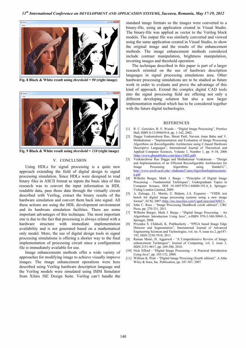
Fig. 8 Black & White result using threshold = 90 (right image)
Fig. 9 Black & White result using threshold = 110 (right image)
V. CONCLUSION
Using HDLs for signal processing is a quite new approach extending the field of digital design to signal processing simulation. Since HDLs were designed to read binary files in ASCII format as inputs the basic idea of this research was to convert the input information in HDL readable data, pass those data through the virtually circuit described with Verilog, extract the binary results of the hardware simulation and convert them back into signal. All these actions are using the HDL development environment and its hardware simulation facilities. There are some important advantages of this technique. The most important one is due to the fact that processing is always related with a hardware structure with immediate implementation availability and is not generated based on a mathematical only model. More, the use of digital design tools in signal processing simulations is offering a shorter way to the final implementation of processing circuit since a configuration file is immediately available for use.
Image enhancements methods offer a wide variety of approaches for modifying image to achieve visually improve images. The image enhancement operations were here described using Verilog hardware description language and the Verilog models were simulated using ISIM Simulator from Xilinx ISE Design Suite. Verilog can’t handle the
standard image formats so the images were converted to a binary-file, using an application created in Visual Studio. The binary-file was applied as vector to the Verilog block models. The output file was similarly converted and viewed using the same application created in Visual Studio, to show the original image and the results of the enhancement methods. The image enhancement methods considered include contrast manipulation, brightness manipulation,inverting images and threshold operation.
The technique described in this paper is part of a larger research oriented on the use of hardware description languages in signal processing simulations area. Other hardware processing simulations are to be studied as future work in order to evaluate and prove the advantage of this kind of approach. Extend the complex digital CAD tools into the signal processing field are offering not only a different developing solution but also a new larger implementation method which has to be considered together with the future digital technologies.
REFERENCES[1] R. C. Gonzalez, R. E. Woods – “Digital Image Processing”, Prentice
Hall, ISBN 0-13-094659-8, pp. 1-142, 2002.[2] Daggu Venkateshwar Rao, Shruti Patil, Naveen Anne Babu and V.
Muthukumar - “Implementation and Evaluation of Image Processing Algorithms on Reconfigurable Architecture using C-based Hardware Descriptive Languages”, International Journal of Theoretical and Applied Computer Sciences, Volume 1, Number 1, pp. 9–34, 2006(http://www.gbspublisher.com/ijtacs/1002.pdf).
[3] Venkateshwar Rao Daggu and Muthukumar Venkatesan – “Design and Implementation of an Efficient Reconfigurable Architecture for Image Processing Algorithms using Handel-C”, http://www.uweb.ucsb.edu/~shahnam/CannyAlgorithmImplementation.pdf
[4] Wilhelm Burger, Mark J. Burge - “Principles of Digital Image Processing – Fundamental Techniques”, Undergraduate Topics in Computer Science, DOI 10.1007/978-1-84800-191-6_4, Springer-Verlag London Limited, 2009.
[5] A. Zuloaga, J.L. Martin, U. Bidarte, J.A. Ezquerra - “VHDL test bench for digital image processing systems using a new image format”, ECSI, 2007 (http://mx.reocities.com/CapeCanaveral/8482/).
[6] John C. Russ - “Image Processing Handbook (sixth edition)”, CRC Press, pp. 270-331, 2011
[7] Wilhelm Burger, Mark J. Burge - “Digital Image Processing – An Algorithmic Introduction Using Java”, e-ISBN 978-3-540-30941-3, Springer, 2008.
[8] Priyanka S. Chikkali, K. Prabhushetty - “FPGA based Image Edge Detector and Segmentation”, International Journal of Advanced Engineering Sciences and Technologies, vol. no. 9, issue no.2, pp187-192, ISSN 2230-7818, 2011.
[9] Raman Maini, H. Aggarwal - “A Comprehensive Review of Image enhancement Techniques”, Journal of Computing, vol. 2, issue 3, ISSN 2151-9617, pp. 269-300, 2010.
[10] Nick Efford - “Digital Image Processing – A Practical Introduction Using Java”, pp. 103-132, 2000.
[11] William K. Pratt - “Digital Image Procesing (fourth edition)”, A John Wiley & Sons, Inc. Publication, pp. 247-307, 2007.


![Design and Implementation of a Digital Image Processor for ... · Enhancement Techniques using Verilog Hardware Description ... binary format for HDL implementation [8] ... The data](https://static.fdocuments.us/doc/165x107/5ace45417f8b9a6a678e8a8b/design-and-implementation-of-a-digital-image-processor-for-techniques-using.jpg)