Image Copier - University of California, San...
31
Image Copier Eric Fisher and Hongrui Wu Motivation and Overall Concept An apparatus was built supporting two axis motion that could position an ambient light sensor and a pin over a platform at various points with accuracy of the relative position of the points within much less than one centimeter. The light sensor was used to store a representation of an image on the platform, and the pin was used to draw a replica of the image. The apparatus, in short, served as a crude copying machine. An image would be sampled at discrete points that formed a rectangular lattice or grid. If the shade of the image at a sample point was darker than a specified threshold, then when the apparatus was to redraw the image it would place a dot on the paper on the platform at that point. Thus the apparatus would draw a dot at all of the darkest areas of the image that fell into the sampling grid, binarizing it. Eric drew the idea of copying an image with a light sensor and a pin from a project proposed by Brian Bagnall in his book Maximum LEGO NXT Building Robots with Java Brains, as a way to use the firmware he developed for the NXT Intelligent Brick from the LEGO GROUP that allows it to be programmed with Java. Our copier was built using much different materials for the mechanical and electrical hardware, on a different platform, and using a different programming language, so although we accomplished the same end goal as Brian Bagnall’s project, it was done in a much different manner. The motivation for choosing to build this particular device for our project, was Eric thought he could perform something visually impressive by processing the image scanned before drawing it. When persons draw pictures they typically do not draw them left to right, bottom to top, pixel by pixel, but instead first draw lines, then color, and then shade, typically using a less systematic approach. If we were to draw ourselves a replica of some other drawing of photograph we would first draw lines at the edges or places of greatest change in the picture. Part of the reason we do that is we use one pin at a time that draws only one point at once. Although not particularly useful for solving any problem, it is impressive to see robots display more human like behavior, and drawing edges could be the way to give the most possible information about an image with only two colors. Despite being the motivation behind the project, this was unfortunately never realized in the final hardware. Despite this, the project still contained some sensing, processing, and motion and drew an interpretation of an image, just not as extensively as planned.
Transcript of Image Copier - University of California, San...

Image Copier Eric Fisher and Hongrui Wu Motivation and Overall Concept An apparatus was built supporting two axis motion that could position an ambient light sensor and a pin over a platform at various points with accuracy of the relative position of the points within much less than one centimeter. The light sensor was used to store a representation of an image on the platform, and the pin was used to draw a replica of the image. The apparatus, in short, served as a crude copying machine. An image would be sampled at discrete points that formed a rectangular lattice or grid. If the shade of the image at a sample point was darker than a specified threshold, then when the apparatus was to redraw the image it would place a dot on the paper on the platform at that point. Thus the apparatus would draw a dot at all of the darkest areas of the image that fell into the sampling grid, binarizing it. Eric drew the idea of copying an image with a light sensor and a pin from a project proposed by Brian Bagnall in his book Maximum LEGO NXT Building Robots with Java Brains, as a way to use the firmware he developed for the NXT Intelligent Brick from the LEGO GROUP that allows it to be programmed with Java. Our copier was built using much different materials for the mechanical and electrical hardware, on a different platform, and using a different programming language, so although we accomplished the same end goal as Brian Bagnall’s project, it was done in a much different manner. The motivation for choosing to build this particular device for our project, was Eric thought he could perform something visually impressive by processing the image scanned before drawing it. When persons draw pictures they typically do not draw them left to right, bottom to top, pixel by pixel, but instead first draw lines, then color, and then shade, typically using a less systematic approach. If we were to draw ourselves a replica of some other drawing of photograph we would first draw lines at the edges or places of greatest change in the picture. Part of the reason we do that is we use one pin at a time that draws only one point at once. Although not particularly useful for solving any problem, it is impressive to see robots display more human like behavior, and drawing edges could be the way to give the most possible information about an image with only two colors. Despite being the motivation behind the project, this was unfortunately never realized in the final hardware. Despite this, the project still contained some sensing, processing, and motion and drew an interpretation of an image, just not as extensively as planned.

Functional Definition We made a mechanical device that can suspend a dolly over a two dimensional image, and this dolly contained a light sensor to measure the darkness of the shades of the image and a pin. The sensor was be held about one centimeter above the image and was be able to move across the breadth of the entire image. The pin could also move across the breadth of a field the same size as the image. A servo motor was used to actuate the pin up and down such that the pin could make a mark at only specific locations on the paper. The range of motion for the dolly was 14 inches across and 16 inches front to back, but of course all of it was never used at once only 8.5 by 11 inches of it. The software that drove the device moved the sensor and pin in a systematic manner. The scanning protocol started with the dolly in one corner of the scanning domain. Call it the upper left corner. The dolly proceeded to move along one dimension, may it be to the right. Once it had moved far enough right to span the domain, it moved along the second dimension, say down, one increment. It then moved to the left across the entire domain, and when it had reached the left bound, it moved down one increment again. This process repeated until it had reached the lower bound of the domain. It then reset to the upper left corner. The device did not sense when it had reached bounds, but considered it has reached a bound when the stepper motors driving the device had moved a certain amount of steps. For our images the domain was 8.5 inches across the first dimension and 11 inches across the second dimension. During the scan routine, every time the dolly moved an increment in any direction, a reading from the sensor was taken of the ambient light value. The spacing between pixels, or light readings, was about 0.34 inches left to right with 25 columns, and about 0.41 inches upwards and downwards with 27 rows. After the scan routine was complete, the software delayed action for 20 seconds, to give time for the operator to replace the image to be scanned, with a blank page for the apparatus to draw on. All lining up of the paper was done manually in this time period. The draw routine was carried out in a similar fashion to the scanning routine, and the dolly was moved in the same pattern. The difference between the draw routine and the scan routine is in the draw routine, at each pixel, instead of measuring the ambient light, the pin would be stabbed into the paper when the ambient light at each pixel, measured during the previous scan routine, is below a specified threshold. Regions on the drawing paper that correspond to darker regions of the scanned image became covered with a grid of dots. The apparatus was controlled by an Arduino Mega 2560 and all software was written in the C language.

Sensor We used an APDS-9960 proximity, ambient light (white light), RGB, and gesture sensor to determine the shade of the image at each pixel. SparkFun had developed an Arduino library for the sensor that was not well documented but ultimately proved easy to use. Only the ambient light functionality was used in this project. The light sensor works simply using a wide spectrum semiconductor photodetector with high sensitivity. The sensor has an integrated LED but according the data sheet, the LED emits in the inferred, and measuring reflected light from it for proximity sensing. A concern brought up in the proposal for this project was the numerical aperture of the opics leading into the photodetector. If the cone of light entering the photodetector were broader than the size of one pixel, details of the image would be lost. In the final demonstration of the project, the pixel size was so large and the reference shapes so simple that this concern was not relevant, but if we were to increase the resolution at which we scan, then it may become one. The proposed solution was to use a metal tube to use as a crude waveguide from the paper to the photodetector. The sensor provides a single value of uint_8 type to the Arduino using the I2C protocol to report the ambient light value to the Arduino. Thus the values it reported are between 0 and 255. For the final presentation the threshold was put at 115, and if the ambient light value at a point on the image was less than 115 a dot would be placed there during the draw routine. Because the sensor used a bias voltage of 3.3 v, a level shifter from 5 v to 3.3 v was placed between the Arduino and the sensor. Mechanical Implementation A wooden frame was built out of four lengths of 2 x 4 lumber fastened together by four wood screws. To prevent parallel motion of the sides of the frame and to provide a platform for the image and paper to draw on, a sheet of plywood with three plies was screwed to the top of the frame. A 2 x 4 beam was then attached to the top of the frame using two 16 inch drawer slides. The drawer slides allowed it to move forward and backward over the frame with sufficiently low friction. The motion of the beam provided one axis of the motion. Two 14 inch drawer slides were placed on top of the beam, and on those the dolly was attached to the beam. The dolly

could then travel side to side on the beam, which allowed for the second axis of the motion. The friction however was not quit low enough. To actuate the beam and dolly, three stepper motors were used, each with 400 steps per rotation. To move the beam, two stepper motors were placed on one end of the frame on opposite sides to move in tandem. The stepper motors drove the beam using an MXL timing belt that was 5 mm in width. The stepper motors drove the belt using sprockets that were 6 mm wide and about 10 mm in diameter. Each stepper motor drove a separate belt one driving each end of the beam, such that one end of the beam would not lag behind the other. Each belt was attached to two pulleys, one driven by a stepper motor, and the other idle. The idler pulleys were mounted using bolts that were held through a slot in a metal plate by two hex nuts and some washers. Because the bolts threaded through slots, the belt tension could be adjusted, and the belts could easily be removed from the pulleys. The belt was attached to the beam using staples. The dolly was actuated on the beam using an almost identical setup but with only one stepper motor and belt instead of two. The pin was stabbed into the paper and lifted back out using a servo motor. The servo motor drove one of three moving metal lengths. The pin was taped to one of the remaining two, and the third one was idle. A serious difficulty encountered with the hardware was one of the drawer slides connecting the dolly to the beam had a fault when used in our application: it would stick in some parts of its travel, particularly when the belt was attached and tensioned. Because the way the location of the next point was determined was relative to the previous point, telling the stepper motor to move a certain amount of steps, if the stepper motor missed a step, because the drawer slide stuck, the rows in the image would be permanently misaligned. This fault was present in the final product. Although we did not think of all these potential solutions at the time, simply slowing the speed of the stepper motor moving the beam on the dolly could have solved the problem, because we noticed that stepper motors perform better at slower speeds. The scanning and drawing process was already very time consuming and difficult to demonstrate at the speed it ran though. We could have also used a larger stepper motor or a second stepper motor like how the beam was actuated. As an interesting idea to avoid this kind of problem in general, one could theoretically create an indexer on the frame and beam to switch from relative position to absolute position. For example, a black and white repeating pattern could be pasted to the beam and frame, and two more light sensors used to read them as the beam or dolly move. When the light readings from the light sensor cross a threshold, the software knows the beam or dolly has moved one pixel more. This would be extremely difficult to realize at a high resolution though. Of course, if we had more time, the first thing we would try is just replace the slide. Which if it worked, would render all of the previous solutions listed unnecessary.

Below is an image of the finished hardware.
Drawing:
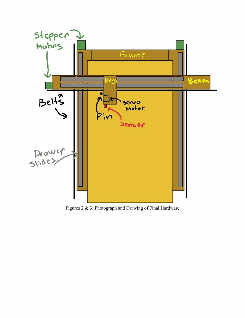
Figures 2 & 3: Photograph and Drawing of Final Hardware

Electrical Implementation We used three stepper motors and drove them with an ADAFruit motor shield v2 . Two of those stepper motors were synchronous so we attached them to the same output on the shield in parallel and treated them as one in the software. The shield proved to be able to supply enough current to make this come to fruition. The shield required an external power supply of 5V. This same external voltage was used for the servo motor and high level for the level shifter, and the shield took care of making sure it maintained a common ground with the Arduino. The servo required only one digital pin from the Arduino and the sensor required only two pins from the Arduino, the SCL and SDA pins. The VCC of 3.3 v for the sensor was provided using the external power supply. The level shifter chip that was mentioned was necessary because the Arduino ran on 5V and the sensor ran on 3.3 V. The total list of electrical components is three stepper motors, one servo motor, one light sensor, one Arduino Mega 2560, an ADAFruit motor shield, a level shifter, an external power supply, and the wires connecting them. To manage the many wires traveling to the dolly and to the stepper motors, we bundled them together with tape. Rarely, but not never, a short circuit would occur due to too much bare wire. The following are diagrams of the electrical implementation.

Figure 4: Electrical Schematic
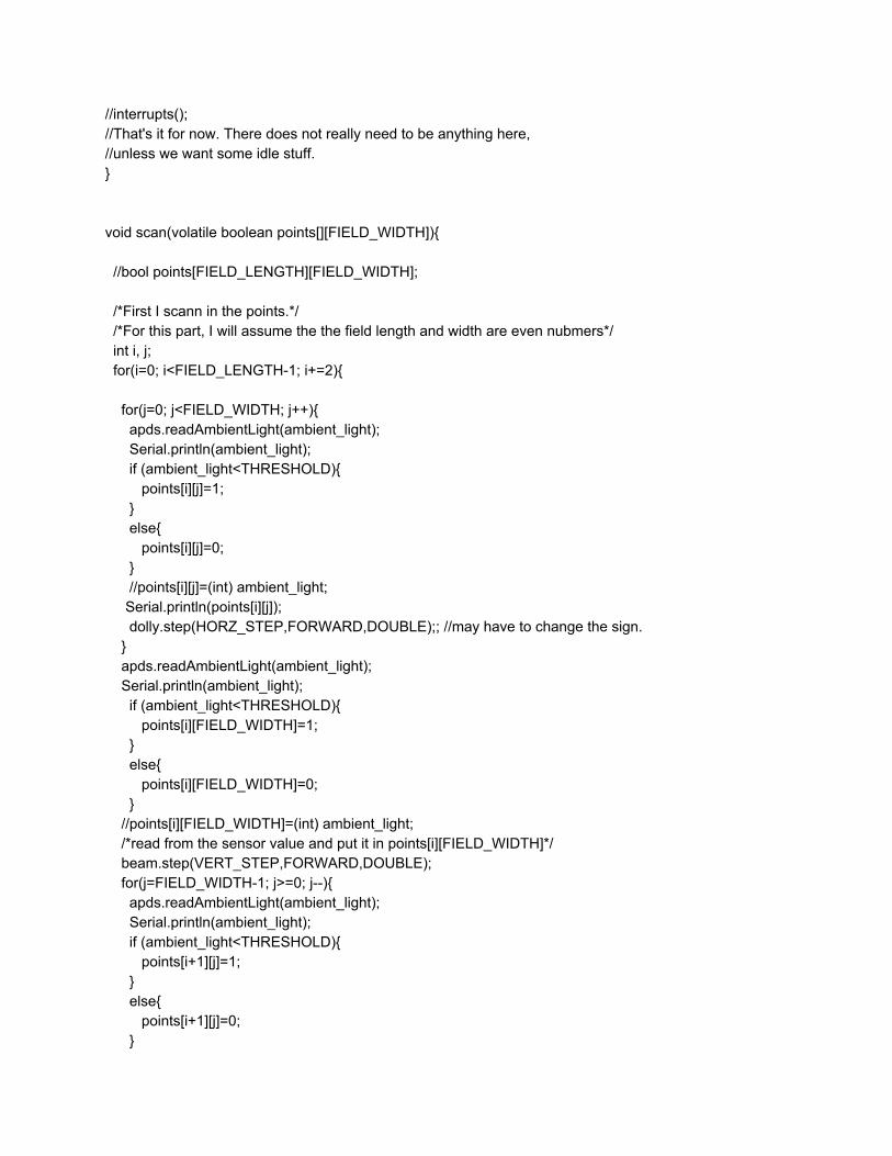
The high resolution image can be accessed here: https://drive.google.com/file/d/161wjb9EQRYdrOtJKFtiJdw4aBEs2e2c1/view?usp=sharing User Interface The end product did not have hardly any user interface and just repeated its routine. This was not the original goal. We originally intended to have the draw and scan routines begin as responses to interrupts. Although we completed the hardware for the interrupts, and tested it, there was a subtle bug in the software that prevented them from working correctly. One possibility is that the interrupts might be interacting with the library for the sensor. Software The following is the completed Arduino code for the project as demonstrated at the final presentation. There are some remnants of using interrupts left in as comments.

#include <Wire.h> #include <AFMotor.h> #include <Servo.h> #include <SparkFun_APDS9960.h> SparkFun_APDS9960 apds = SparkFun_APDS9960(); uint16_t ambient_light = 0; AF_Stepper beam(400, 2); AF_Stepper dolly(400, 1); Servo pin; const int FIELD_LENGTH=27/*How many pixels high is the paper*/; const int FIELD_WIDTH=25/*How many pixels wide is the paper*/; const int VERT_STEP=50/*How many steps on a stepper motor movess down one pixel*/; const int HORZ_STEP=43/*How many steps on a stepper motor movess accross one pixel*/; const int SENSE_MAX=255/*The maximum sensor value*/; const int SENSE_MIN=0/*The minimum sensor value*/; const float PICKUP_THRESHOLD=1/*how far the pen needs to moves for it to be picked up*/; const int THRESHOLD=115; /*we shall tune this as needed*/ const int UPANGLE=20; const int DOWNANGLE=0; volatile boolean points[FIELD_LENGTH][FIELD_WIDTH]; void setup() { // put your setup code here, to run once: // stepper.setSpeed(/*probably pretty fast*/); //attachInterrupt(/*pin*/, scan, RISING); //attachInterrupt(/*pin*/, draw, RISING); Serial.begin(9600); apds.init(); apds.enableLightSensor(false); beam.setSpeed(10); dolly.setSpeed(10); pin.attach(22, 450, 2500); //***ADD PULSE TIMES!*** /*We also may need to do some pin modes*/ } void loop() { scan(points); delay(20000); draw(points); // put your main code here, to run repeatedly:
//interrupts(); //That's it for now. There does not really need to be anything here, //unless we want some idle stuff. } void scan(volatile boolean points[][FIELD_WIDTH]){ //bool points[FIELD_LENGTH][FIELD_WIDTH]; /*First I scann in the points.*/ /*For this part, I will assume the the field length and width are even nubmers*/ int i, j; for(i=0; i<FIELD_LENGTH-1; i+=2){ for(j=0; j<FIELD_WIDTH; j++){ apds.readAmbientLight(ambient_light); Serial.println(ambient_light); if (ambient_light<THRESHOLD){ points[i][j]=1; } else{ points[i][j]=0; } //points[i][j]=(int) ambient_light; Serial.println(points[i][j]); dolly.step(HORZ_STEP,FORWARD,DOUBLE);; //may have to change the sign. } apds.readAmbientLight(ambient_light); Serial.println(ambient_light); if (ambient_light<THRESHOLD){ points[i][FIELD_WIDTH]=1; } else{ points[i][FIELD_WIDTH]=0; } //points[i][FIELD_WIDTH]=(int) ambient_light; /*read from the sensor value and put it in points[i][FIELD_WIDTH]*/ beam.step(VERT_STEP,FORWARD,DOUBLE); for(j=FIELD_WIDTH-1; j>=0; j--){ apds.readAmbientLight(ambient_light); Serial.println(ambient_light); if (ambient_light<THRESHOLD){ points[i+1][j]=1; } else{ points[i+1][j]=0; }

//points[i+1][j]=(int) ambient_light; Serial.println(points[i][j]); /*read from the sensor and put the value in points[i+1][j]*/ dolly.step(HORZ_STEP,BACKWARD,DOUBLE);// may have to change the sign. } apds.readAmbientLight(ambient_light); Serial.println(ambient_light); if (ambient_light<THRESHOLD){ points[i+1][0]=1; } else{ points[i+1][0]=0; } //points[i+1][0]=(int) ambient_light; /*read sensor value and put it into points[i+1][0]*/ beam.step(VERT_STEP,FORWARD,DOUBLE); } for(j=0; j<FIELD_WIDTH; j++){ apds.readAmbientLight(ambient_light); //Serial.println(ambient_light); if (ambient_light<THRESHOLD){ points[FIELD_LENGTH-1][j]=1; } else{ points[FIELD_LENGTH-1][j]=0; } //points[FIELD_LENGTH-1][j]=(int) ambient_light; Serial.println(points[i][j]); /*read from the sensor and put the value in points[i][j]*/ dolly.step(HORZ_STEP,FORWARD,DOUBLE); //may have to change the sign. } apds.readAmbientLight(ambient_light); Serial.println(ambient_light); if (ambient_light<THRESHOLD){ points[FIELD_LENGTH-1][FIELD_WIDTH]=1; } else{ points[FIELD_LENGTH-1][FIELD_WIDTH]=0; } //points[FIELD_LENGTH-1][FIELD_WIDTH]=(int) ambient_light; /*read om thee sensor value and put it in points[i][FIELD_WIDTH]*/ beam.step(VERT_STEP,FORWARD,DOUBLE); for(j=FIELD_WIDTH-1; j>=0; j--){ apds.readAmbientLight(ambient_light); Serial.println(ambient_light); if (ambient_light<THRESHOLD){ points[FIELD_LENGTH][j]=1; }

else{ points[FIELD_LENGTH][j]=0; } //points[FIELD_LENGTH][j]=(int) ambient_light; Serial.println(points[FIELD_LENGTH][j]); /*read from the sensor and put the value in points[i+1][j]*/ dolly.step(HORZ_STEP,BACKWARD,DOUBLE);// may have to change the sign. } apds.readAmbientLight(ambient_light); Serial.println(ambient_light); if (ambient_light<THRESHOLD){ points[FIELD_LENGTH][0]=1; } else{ points[FIELD_LENGTH][0]=0; } /*read sensor value and put it into points[i+1][0]*/ //points[FIELD_LENGTH][0]=(int) ambient_light; beam.step(VERT_STEP*(FIELD_LENGTH),BACKWARD,DOUBLE); //SCAN COMPLETE ................................................................................. } void draw(volatile boolean points[][FIELD_WIDTH]){ int i, j; for(i=0; i<FIELD_LENGTH-1; i+=2){ for(j=0; j<FIELD_WIDTH; j++){ if (points[i][j]==1){ Serial.println("I hit a 1"); pin.write(DOWNANGLE); //delayMicroseconds(10000); delay(500); pin.write(UPANGLE); delay(500); } dolly.step(HORZ_STEP,FORWARD,DOUBLE);; //may have to change the sign. } if ( points[i][FIELD_WIDTH]==1){ Serial.println("I hit a 1"); pin.write(DOWNANGLE); //delayMicroseconds(10000); delay(500); pin.write(UPANGLE); delay(500); } beam.step(VERT_STEP,FORWARD,DOUBLE);

for(j=FIELD_WIDTH-1; j>=0; j--){ if (points[i+1][j]==1){ Serial.println("I hit a 1"); pin.write(DOWNANGLE); //delayMicroseconds(10000); delay(500); pin.write(UPANGLE); delay(500); } dolly.step(HORZ_STEP,BACKWARD,DOUBLE);// may have to change the sign. } if (points[i+1][0]==1){ Serial.println("I hit a 1"); pin.write(DOWNANGLE); //delayMicroseconds(10000); delay(500); pin.write(UPANGLE); delay(500); } beam.step(VERT_STEP,FORWARD,DOUBLE); } for(j=0; j<FIELD_WIDTH; j++){ if (points[FIELD_LENGTH-1][j]==1){ pin.write(DOWNANGLE); //delayMicroseconds(10000); delay(500); pin.write(UPANGLE); delay(500); } dolly.step(HORZ_STEP,FORWARD,DOUBLE); //may have to change the sign. } if (points[FIELD_LENGTH-1][FIELD_WIDTH]==1){ pin.write(DOWNANGLE); //delayMicroseconds(10000); delay(500); pin.write(UPANGLE); delay(500); } beam.step(VERT_STEP,FORWARD,DOUBLE); for(j=FIELD_WIDTH-1; j>=0; j--){ if (points[FIELD_LENGTH][j]==1){ pin.write(DOWNANGLE); //delayMicroseconds(10000); delay(500); pin.write(UPANGLE); delay(500); } dolly.step(HORZ_STEP,BACKWARD,DOUBLE);// may have to change the sign.

} if (points[FIELD_LENGTH][0]==1){ pin.write(DOWNANGLE); //delayMicroseconds(10000); delay(500); pin.write(UPANGLE); delay(500); } beam.step(VERT_STEP*(FIELD_LENGTH),BACKWARD,DOUBLE); } Testing The scanning was tested via performing the scanning over an image with high contrast, and printing the values from the sensor to to the serial monitor. After the scanning was shown to perform correctly, the drawing was then added without being tested separately, and after the scanning started working the drawing actually worked on the first try. Results These images show a reference image overlaid with the output of the copier, displaying the performance of the copier.

Safety No safety hazards were encountered when building and operating the device, but some certainly could have occurred. In order to drive two stepper motors in parallel with motor shield the current limit on the bench power supply was turned up close to maximum. We made some shorts by accident sometimes, but each time the current limit on the power supply still kicked in nothing burned. The servo motor got very hot once for a reason we have still not determined, but that was resolved after decreasing the array size of the image and it did not happen again. Parts and Reusability The Arduino Mega 2560; ADAFruit motor shield; stepper motors; servo motor; SparkFun light, RGB, proximity, and gesture sensor; level shifter; wires; breadboard; and masking tape; and bench powers supply were provided through the lab and returned to the lab. All remaining components were supplied by us. The Arduino Mega 2560 will surely be useful for future Phys 124 students, and the sensor was a reuse of a previous group’s component. Descoping of the Project A large element of this project was to perform edge detecting on the image after it was scanned. The reason this never came to fruition is because the Arduino Mega 2560 did not have enough random access memory to store floating point or integer arrays of the quantity and size needed. In order to succeed in this endeavor, we would have needed access to more memory. One of the ways to do this is by adding an micro SD card. The complication with using a micro SD card is that the data needs to be stored in it in files, and to rewrite our code to incorporate it we would need of mimic the behavior of array indexing with files. That is possible, but in C it can be rather complicated and time consuming to write. Adding another Arduino would only add 32 kB of memory to the Arduino Mega 2560’s 256 kB, which would not help enough to make a difference. A BeagleBone Black has 512 MB of memory which is much larger than 256 kB not including the 4 GB of flash memory. With a BeagleBone, the copier could be programmed with python. In the OpenCV library for python, there is a function called cv2.Canny() which could potentially replicate all of the steps of edge detection with us only writing one line of code. That would not have made for a very uninteresting project, and using a less powerful tool would be much more interesting. As for the progress of developing the edge detector, here is some code that we wrote for a computer to compile and run, that is fully debugged and works correctly. The array named image is a simple image hardcoded in that is only 20 by 20. The program prints two arrays to the

screen. One is a 20 by 20 edge image. For this simple contrived image there is a tie for max gradient on one the right line but not the left, but that is certainly something to do with machine precision. The second array is 3 by 400, named mover, and each row is considered one move. There are fewer than 400 edge points but the array size is chosen for the worst case. It contains the instructions for the draw function on how to move the pin to connect one edge point to the next. The first element is the direction and amount to move the beam to get to the next edge point, the second element is how far to move the dolly, and the third element determines whether or not the pin should be lifted during the motion. 1 means lift the pin and 0 means do not. Also, for the purposes of interpreting this code, the most interesting part is in the sobel function. The 3 by 3 arrays called the Sobel operators are what take the gradient of the image and hense find the edges. #include <stdio.h> #include <math.h> typedef int bool; #define true 1 #define false 0 #define PI 3.141592653589793 #define FIELD_LENGTH 20 #define FIELD_WIDTH 20 void smoother(int image[][FIELD_WIDTH], float smooth[][FIELD_WIDTH]); void sobel(float smooth[][FIELD_WIDTH], float phase[][FIELD_WIDTH], float magnitude[][FIELD_WIDTH]); void thiner(float magnitude[][FIELD_WIDTH],float phase[][FIELD_WIDTH], float thin[][FIELD_WIDTH]); void threshold(float magnitude[][FIELD_WIDTH], bool points[][FIELD_WIDTH]); void prepare(bool points[][FIELD_WIDTH], int sequence[][2]); void mover(int sequence [][2], int moves[][3]); float max(float a, float b){ if(a>=b){ return a; } else{ return b; } } int main() { int image[][FIELD_WIDTH]={{0,0,0,0,0,255,255,255,255,255,255,255,255,255,255,0,0,0,0,0}, {0,0,0,0,0,255,255,255,255,255,255,255,255,255,255,0,0,0,0,0}, {0,0,0,0,0,255,255,255,255,255,255,255,255,255,255,0,0,0,0,0},

{0,0,0,0,0,255,255,255,255,255,255,255,255,255,255,0,0,0,0,0}, {0,0,0,0,0,255,255,255,255,255,255,255,255,255,255,0,0,0,0,0}, {0,0,0,0,0,255,255,255,255,255,255,255,255,255,255,0,0,0,0,0}, {0,0,0,0,0,255,255,255,255,255,255,255,255,255,255,0,0,0,0,0}, {0,0,0,0,0,255,255,255,255,255,255,255,255,255,255,0,0,0,0,0}, {0,0,0,0,0,255,255,255,255,255,255,255,255,255,255,0,0,0,0,0}, {0,0,0,0,0,255,255,255,255,255,255,255,255,255,255,0,0,0,0,0}, {0,0,0,0,0,255,255,255,255,255,255,255,255,255,255,0,0,0,0,0}, {0,0,0,0,0,255,255,255,255,255,255,255,255,255,255,0,0,0,0,0}, {0,0,0,0,0,255,255,255,255,255,255,255,255,255,255,0,0,0,0,0}, {0,0,0,0,0,255,255,255,255,255,255,255,255,255,255,0,0,0,0,0}, {0,0,0,0,0,255,255,255,255,255,255,255,255,255,255,0,0,0,0,0}, {0,0,0,0,0,255,255,255,255,255,255,255,255,255,255,0,0,0,0,0}, {0,0,0,0,0,255,255,255,255,255,255,255,255,255,255,0,0,0,0,0}, {0,0,0,0,0,255,255,255,255,255,255,255,255,255,255,0,0,0,0,0}, {0,0,0,0,0,255,255,255,255,255,255,255,255,255,255,0,0,0,0,0}, {0,0,0,0,0,255,255,255,255,255,255,255,255,255,255,0,0,0,0,0}}; float smooth[FIELD_LENGTH][FIELD_WIDTH]; float magnitude[FIELD_LENGTH][FIELD_WIDTH]; float phase[FIELD_LENGTH][FIELD_WIDTH]; float thin[FIELD_LENGTH][FIELD_WIDTH]; bool points[FIELD_LENGTH][FIELD_WIDTH]; int sequence[FIELD_LENGTH*FIELD_WIDTH][2]; int move[FIELD_LENGTH*FIELD_WIDTH][3]; smoother(image, smooth); sobel(smooth, phase, magnitude); thiner(magnitude , phase, thin); threshold(thin, points); int i,j; for(i=0; i<FIELD_LENGTH; i++){
for(j=0; j<FIELD_WIDTH; j++){ printf("%d ", ((int) points[i][j]));
} printf("\n");
} prepare(points, sequence); mover(sequence, move); for(i=0; i<FIELD_LENGTH*FIELD_WIDTH; i++){
for(j=0; j<3; j++){ printf("%d ", ((int) move[i][j]));
} printf("\n");

}
return 0; } void smoother(int image[][FIELD_WIDTH], float smooth[][FIELD_WIDTH]){ float gauss[][5]={{2.0/159.0, 4.0/159.0, 5.0/159.0, 4.0/159.0, 2.0/159.0}, {4.0/159.0, 9.0/159.0, 12.0/159.0, 9.0/159.0, 4.0/159.0}, {5.0/159.0, 12.0/159.0, 15.0/159.0, 12.0/159.0, 5.0/159.0}, {4.0/159.0, 9.0/159.0, 12.0/159.0, 9.0/159.0, 4.0/159.0}, {2.0/159.0, 4.0/159.0, 5.0/159.0, 4.0/159.0, 2.0/159.0}}; float padded[FIELD_LENGTH+4][FIELD_WIDTH+4]; int i; int j; for(i=0; i<FIELD_LENGTH+4; i++){ for (j=0; j<FIELD_WIDTH+4; j++){ padded[i][j]=0; //Note, you may want change the pad value. } } for(i=0; i<FIELD_LENGTH; i++){ for (j=0; j<FIELD_WIDTH; j++){ padded[i+2][j+2]=image[i][j]; } } int k; int l; float cumsum=0.0; for(i=2; i<FIELD_LENGTH+2; i++){ for (j=2; j<FIELD_WIDTH+2; j++){ for (k=i-2; k<i+3; k++){ for(l=j-2; l<j+3; l++){ cumsum+=(float)padded[k][l]*gauss[k+2-i][l+2-j]; } } smooth[i-2][j-2]=cumsum; cumsum=0.0; } } } void sobel(float smooth[][FIELD_WIDTH], float phase[][FIELD_WIDTH], float magnitude[][FIELD_WIDTH]) { float sobel_vert[][3]={ {-1.0, 0.0, 1.0}, {-2.0, 0.0, 2.0},{-1.0, 0.0, 1.0}}; float sobel_horz[][3]={ {-1.0, -2.0, -1.0}, {0.0, 0.0, 0.0},{1.0, 2.0, 1.0}}; float padded2[FIELD_LENGTH+2][FIELD_WIDTH+2];

int i; int j; for(i=0; i<FIELD_LENGTH+2; i++){ for (j=0; j<FIELD_WIDTH+2; j++){ padded2[i][j]=0; //Note, you may want change the pad value. } } for(i=0; i<FIELD_LENGTH; i++){ for (j=0; j<FIELD_WIDTH; j++){ padded2[i+1][j+1]=smooth[i][j]; } } float edge_vert[FIELD_LENGTH][FIELD_WIDTH]; float edge_horz[FIELD_LENGTH][FIELD_WIDTH]; int k; int l; float vertcumsum=0.0; for(i=1; i<FIELD_LENGTH+1; i++){ for (j=1; j<FIELD_WIDTH+1; j++){ for (k=i-1; k<i+2; k++){ for(l=j-1; l<j+2; l++){ vertcumsum+=padded2[k][l]*sobel_vert[k+1-i][l+1-j]; } } edge_vert[i-1][j-1]=vertcumsum; vertcumsum=0.0; } } float horzcumsum=0.0; for(i=1; i<FIELD_LENGTH+1; i++){ for (j=1; j<FIELD_WIDTH+1; j++){ for (k=i-1; k<i+2; k++){ for(l=j-1; l<j+2; l++){ horzcumsum+=padded2[k][l]*sobel_horz[k+1-i][l+1-j]; } } edge_horz[i-1][j-1]=horzcumsum; horzcumsum=0.0; } } for(i=0; i<FIELD_LENGTH; i++){ for(j=0; j<FIELD_WIDTH; j++){

magnitude[i][j]= sqrt(edge_vert[i][j]*edge_vert[i][j]+edge_horz[i][j]*edge_horz[i][j]); phase[i][j] = atan(edge_horz[i][j]/edge_vert[i][j]); } } } void thiner(float magnitude[][FIELD_WIDTH],float phase[][FIELD_WIDTH], float thin[][FIELD_WIDTH]){ int i,j; for(i=0; i<FIELD_LENGTH; i++){ for(j=0; j<FIELD_WIDTH; j++){ if (phase[i][j]>3.0/8.0*PI || phase[i][j]<-3.0/8.0*PI){ phase[i][j]=90.0; } else if(phase[i][j]<3.0/8.0*PI && phase[i][j]>1.0/8.0*PI){ phase[i][j]=45.0; } else if(phase[i][j]<1.0/8.0*PI && phase[i][j]>-1.0/8.0*PI){ phase[i][j]=0.0; } else if(phase[i][j]<-1.0/8.0*PI && phase[i][j]>-3.0/8.0*PI){ phase[i][j]=-45.0; } } } for(i=0; i<FIELD_LENGTH; i++){ for(j=0; j<FIELD_WIDTH; j++){ thin[i][j]=magnitude[i][j]; } } for(i=1; i<FIELD_LENGTH-1; i++){ for(j=1; j<FIELD_WIDTH-1; j++){ if (phase[i][j] ==0.0){ if (magnitude[i][j] < max(magnitude[i][j-1],magnitude[i][j+1])){ thin[i][j] = 0.0; } } else if (phase[i][j] ==-45.0){ if (magnitude[i][j] < max(magnitude[i+1][j-1],magnitude[i-1][j+1])){ thin[i][j] = 0.0; } } else if (phase[i][j] ==45.0){ if (magnitude[i][j] < max(magnitude[i+1][j+1],magnitude[i-1][j-1])){

thin[i][j] = 0.0; } } else if (phase[i][j] ==90.0){ if (magnitude[i][j] < max(magnitude[i-1][j],magnitude[i+1][j])){ thin[i][j] = 0.0; } } } } } void threshold(float thin[][FIELD_WIDTH], bool points[][FIELD_WIDTH]){ int i,j; float maximum = 0.0; for(i=1; i<FIELD_LENGTH-1; i++){ for(j=1; j<FIELD_WIDTH-1; j++){ maximum = max(maximum, thin[i][j]); } } float threshold = 0.12*maximum; //may change number as needed for(i=1; i<FIELD_LENGTH-1; i++){ for(j=1; j<FIELD_WIDTH-1; j++){ if( thin[i][j] > threshold) { points[i][j]= true; } else { points[i][j]= false; } } } } void prepare(bool points[][FIELD_WIDTH], int sequence[][2]){ int i,j; int k=FIELD_LENGTH, l=FIELD_WIDTH; for(i=0; i<FIELD_LENGTH; i++){ for(j=0; j<FIELD_WIDTH; j++){ if(points[i][j]==1){ k=i; l=j; break; } } if(k!=FIELD_LENGTH){ break; } }

sequence[0][0]=k; sequence[0][1]=l; points[k][l]=0; int q; for(q=1; q<FIELD_LENGTH*FIELD_WIDTH; q++){
float distance=(float) FIELD_LENGTH + (float) FIELD_WIDTH; for(i=0; i<FIELD_LENGTH; i++){ for(j=0; j<FIELD_WIDTH; j++){
if (points[i][j]==1){
if(sqrt((i-sequence[q-1][0])*(i-sequence[q-1][0])+(j-sequence[q-1][1])*(j-sequence[q-1][1]))<distance){
distance=sqrt((i-sequence[q-1][0])*(i-sequence[q-1][0])+(j-sequence[q-1][1])*(j-sequence[q-1][1])); k=i; l=j;
} }
} } sequence[q][0]=k;
sequence[q][1]=l; points[k][l]=0;
if (distance==FIELD_LENGTH+FIELD_WIDTH){ sequence[q][0]=0; sequence[q][1]=0; break;
} } } void mover(int sequence [][2], int move[][3]){ move[0][0]=sequence[0][0]; move[0][1]=sequence[0][1]; int i; for(i=1; i<FIELD_LENGTH*FIELD_WIDTH; i++){ move[i][0]=sequence[i][0]-sequence[i-1][0]; move[i][1]=sequence[i][1]-sequence[i-1][1]; } for(i=0; i<FIELD_LENGTH*FIELD_WIDTH; i++){ if(sqrt((float) move[i][0]* (float) move[i][0]+(float) move[i][1]* (float) move[i][1])>1.5){ move[i][2]=1; } else { move[i][2]=0; } } }

The following code is code that would be run on a fictition device that would be just like an Arduino but with unlimited memory. The code is an attempt at creating a complete program that is ready to run on such a fictitious device. Because the draw function could not be tested it could theoretically contain a bug, but all the other sub functions have been tested on one platform or another. It will compile for Arduino with no errors if the size of sequence is not too large. #include <Wire.h> #include <AFMotor.h> #include <Servo.h> #include <SparkFun_APDS9960.h> SparkFun_APDS9960 apds = SparkFun_APDS9960(); uint16_t ambient_light = 0; AF_Stepper beam(400, 2); AF_Stepper dolly(400, 1); Servo pin; const int FIELD_LENGTH=27/*How many pixels high is the paper*/; const int FIELD_WIDTH=25/*How many pixels wide is the paper*/; const int VERT_STEP=50/*How many steps on a stepper motor movess down one pixel*/; const int HORZ_STEP=43/*How many steps on a stepper motor movess accross one pixel*/; const int UPANGLE=20; const int DOWNANGLE=0; volatile int sequence[FIELD_LENGTH*FIELD_WIDTH][2]; void setup() { // put your setup code here, to run once: // stepper.setSpeed(/*probably pretty fast*/); //attachInterrupt(/*pin*/, scan, RISING); //attachInterrupt(/*pin*/, draw, RISING); Serial.begin(9600); apds.init(); apds.enableLightSensor(false); beam.setSpeed(20); dolly.setSpeed(20); pin.attach(22, 450, 2500); } void loop() { scan(sequence); delay(20000);

draw(sequence); delay(20000); // put your main code here, to run repeatedly: //interrupts(); } void smoother(int image[][FIELD_WIDTH], float smooth[][FIELD_WIDTH]); void sobel(float smooth[][FIELD_WIDTH], float phase[][FIELD_WIDTH], float magnitude[][FIELD_WIDTH]); void thiner(float magnitude[][FIELD_WIDTH],float phase[][FIELD_WIDTH], float thin[][FIELD_WIDTH]); void threshold(float magnitude[][FIELD_WIDTH], bool points[][FIELD_WIDTH]); void prepare(bool points[][FIELD_WIDTH], int sequence[][2]); void movesr(int sequence [][2], int moves[][3]); void scan(int sequence[][2]){ int image[FIELD_LENGTH][FIELD_WIDTH]; float smooth[FIELD_LENGTH][FIELD_WIDTH]; float magnitude[FIELD_LENGTH][FIELD_WIDTH]; float phase[FIELD_LENGTH][FIELD_WIDTH]; float thin[FIELD_LENGTH][FIELD_WIDTH]; bool points[FIELD_LENGTH][FIELD_WIDTH]; /*First I scann in the image.*/ /*For this part, I will assume the the field length and width are even nubmers*/ int i, j; for(i=0; i<FIELD_LENGTH-1; i+=2){ for(j=0; j<FIELD_WIDTH; j++){ apds.readAmbientLight(ambient_light); image[i][j]=(int) ambient_light; Serial.println(image[i][j]); dolly.step(HORZ_STEP,FORWARD,DOUBLE);; //may have to change the sign. } apds.readAmbientLight(ambient_light); image[i][FIELD_WIDTH]=(int) ambient_light; /*read om thee sensor value and put it in image[i][FIELD_WIDTH]*/ beam.step(VERT_STEP,FORWARD,DOUBLE); for(j=FIELD_WIDTH-1; j>=0; j--){ apds.readAmbientLight(ambient_light); image[i+1][j]=(int) ambient_light; Serial.println(image[i][j]); /*read from the sensor and put the value in image[i+1][j]*/ dolly.step(HORZ_STEP,BACKWARD,DOUBLE);;// may have to change the sign. } apds.readAmbientLight(ambient_light); image[i+1][0]=(int) ambient_light; /*read sensor value and put it into image[i+1][0]*/

beam.step(VERT_STEP,FORWARD,DOUBLE); } for(j=0; j<FIELD_WIDTH; j++){ apds.readAmbientLight(ambient_light); image[FIELD_LENGTH-1][j]=(int) ambient_light; Serial.println(image[i][j]); /*read from the sensor and put the value in image[i][j]*/ dolly.step(HORZ_STEP,FORWARD,DOUBLE); //may have to change the sign. } apds.readAmbientLight(ambient_light); image[FIELD_LENGTH-1][FIELD_WIDTH]=(int) ambient_light; /*read om thee sensor value and put it in image[i][FIELD_WIDTH]*/ beam.step(VERT_STEP,FORWARD,DOUBLE); for(j=FIELD_WIDTH-1; j>=0; j--){ apds.readAmbientLight(ambient_light); image[FIELD_LENGTH][j]=(int) ambient_light; Serial.println(image[i][j]); /*read from the sensor and put the value in image[i+1][j]*/ dolly.step(HORZ_STEP,BACKWARD,DOUBLE);// may have to change the sign. } apds.readAmbientLight(ambient_light); /*read sensor value and put it into image[i+1][0]*/ image[FIELD_LENGTH][0]=(int) ambient_light; beam.step(VERT_STEP*(FIELD_LENGTH),BACKWARD,DOUBLE); //SCAN COMPLETE ................................................................................. /*smoother(int image[][FIELD_WIDTH], float smooth[][FIELD_WIDTH]); sobel(float smooth[][FIELD_WIDTH], float phase[][FIELD_WIDTH], float magnitude[][FIELD_WIDTH]); thiner(float magnitude[][FIELD_WIDTH],float phase[][FIELD_WIDTH], float thin[][FIELD_WIDTH]); threshold(float magnitude[][], boolean points[][]); */ smoother(image, smooth); sobel(smooth, phase, magnitude); thiner(magnitude , phase, thin); threshold(thin, points); prepare(points,sequence); } void draw(int sequence[][2]){ int moves[FIELD_LENGTH*FIELD_WIDTH][3]; movesr(sequence,moves); pin.write(DOWNANGLE); int i=0; while(sequence[i][0]!=0 && sequence[i][1]!=0){ if (moves[i][2]==1){ pin.write(UPANGLE); if(moves[i][0] > 0) { beam.step(VERT_STEP*moves[i][0], FORWARD, DOUBLE);

} else{ beam.step(-VERT_STEP*moves[i][0], BACKWARD, DOUBLE); } if(moves[i][1] > 0) { dolly.step(HORZ_STEP*moves[i][1], FORWARD, DOUBLE); } else{ dolly.step(-HORZ_STEP*moves[i][1], BACKWARD, DOUBLE); } pin.write(DOWNANGLE); } else { if(moves[i][0] > 0) { beam.step(VERT_STEP*moves[i][0], FORWARD, DOUBLE); } else{ beam.step(-VERT_STEP*moves[i][0], BACKWARD, DOUBLE); } if(moves[i][1] > 0) { dolly.step(HORZ_STEP*moves[i][1], FORWARD, DOUBLE); } else{ dolly.step(-HORZ_STEP*moves[i][1], BACKWARD, DOUBLE); } } i++; } pin.write(UPANGLE); beam.step(-sequence[i-1][0],BACKWARD, DOUBLE); dolly.step(-sequence[i-1][1],BACKWARD, DOUBLE); } void smoother(int image[][FIELD_WIDTH], float smooth[][FIELD_WIDTH]){ float gauss[][5]={{2.0/159.0, 4.0/159.0, 5.0/159.0, 4.0/159.0, 2.0/159.0}, {4.0/159.0, 9.0/159.0, 12.0/159.0, 9.0/159.0, 4.0/159.0}, {5.0/159.0, 12.0/159.0, 15.0/159.0, 12.0/159.0, 5.0/159.0}, {4.0/159.0, 9.0/159.0, 12.0/159.0, 9.0/159.0, 4.0/159.0}, {2.0/159.0, 4.0/159.0, 5.0/159.0, 4.0/159.0, 2.0/159.0}}; float padded[FIELD_LENGTH+4][FIELD_WIDTH+4]; int i; int j; for(i=0; i<FIELD_LENGTH+4; i++){ for (j=0; j<FIELD_WIDTH+4; j++){ padded[i][j]=0; //Note, you may want change the pad value. }

} for(i=0; i<FIELD_LENGTH; i++){ for (j=0; j<FIELD_WIDTH; j++){ padded[i+2][j+2]=image[i][j]; } } int k; int l; float cumsum=0.0; for(i=2; i<FIELD_LENGTH+2; i++){ for (j=2; j<FIELD_WIDTH+2; j++){ for (k=i-2; k<i+3; k++){ for(l=j-2; l<j+3; l++){ cumsum+=(float)padded[k][l]*gauss[k+2-i][l+2-j]; } } smooth[i-2][j-2]=cumsum; cumsum=0.0; } } } void sobel(float smooth[][FIELD_WIDTH], float phase[][FIELD_WIDTH], float magnitude[][FIELD_WIDTH]) { float sobel_vert[][3]={ {-1.0, 0.0, 1.0}, {-2.0, 0.0, 2.0},{-1.0, 0.0, 1.0}}; float sobel_horz[][3]={ {-1.0, -2.0, -1.0}, {0.0, 0.0, 0.0},{1.0, 2.0, 1.0}}; float padded2[FIELD_LENGTH+2][FIELD_WIDTH+2]; int i; int j; for(i=0; i<FIELD_LENGTH+2; i++){ for (j=0; j<FIELD_WIDTH+2; j++){ padded2[i][j]=0; //Note, you may want change the pad value. } } for(i=0; i<FIELD_LENGTH; i++){ for (j=0; j<FIELD_WIDTH; j++){ padded2[i+1][j+1]=smooth[i][j]; } } float edge_vert[FIELD_LENGTH][FIELD_WIDTH]; float edge_horz[FIELD_LENGTH][FIELD_WIDTH]; int k; int l; float vertcumsum=0.0;

for(i=1; i<FIELD_LENGTH+1; i++){ for (j=1; j<FIELD_WIDTH+1; j++){ for (k=i-1; k<i+2; k++){ for(l=j-1; l<j+2; l++){ vertcumsum+=padded2[k][l]*sobel_vert[k+1-i][l+1-j]; } } edge_vert[i-1][j-1]=vertcumsum; vertcumsum=0.0; } } float horzcumsum=0.0; for(i=1; i<FIELD_LENGTH+1; i++){ for (j=1; j<FIELD_WIDTH+1; j++){ for (k=i-1; k<i+2; k++){ for(l=j-1; l<j+2; l++){ horzcumsum+=padded2[k][l]*sobel_horz[k+1-i][l+1-j]; } } edge_horz[i-1][j-1]=horzcumsum; horzcumsum=0.0; } } for(i=0; i<FIELD_LENGTH; i++){ for(j=0; j<FIELD_WIDTH; j++){ magnitude[i][j]= sqrt(edge_vert[i][j]*edge_vert[i][j]+edge_horz[i][j]*edge_horz[i][j]); phase[i][j] = atan(edge_horz[i][j]/edge_vert[i][j]); } } } void thiner(float magnitude[][FIELD_WIDTH],float phase[][FIELD_WIDTH], float thin[][FIELD_WIDTH]){ int i,j; for(i=0; i<FIELD_LENGTH; i++){ for(j=0; j<FIELD_WIDTH; j++){ if (phase[i][j]>3.0/8.0*PI || phase[i][j]<-3.0/8.0*PI){ phase[i][j]=90.0; } else if(phase[i][j]<3.0/8.0*PI && phase[i][j]>1.0/8.0*PI){ phase[i][j]=45.0; } else if(phase[i][j]<1.0/8.0*PI && phase[i][j]>-1.0/8.0*PI){

phase[i][j]=0.0; } else if(phase[i][j]<-1.0/8.0*PI && phase[i][j]>-3.0/8.0*PI){ phase[i][j]=-45.0; } } } for(i=0; i<FIELD_LENGTH; i++){ for(j=0; j<FIELD_WIDTH; j++){ thin[i][j]=magnitude[i][j]; } } for(i=1; i<FIELD_LENGTH-1; i++){ for(j=1; j<FIELD_WIDTH-1; j++){ if (phase[i][j] ==0.0){ if (magnitude[i][j] < max(magnitude[i][j-1],magnitude[i][j+1])){ thin[i][j] = 0.0; } } else if (phase[i][j] ==-45.0){ if (magnitude[i][j] < max(magnitude[i+1][j-1],magnitude[i-1][j+1])){ thin[i][j] = 0.0; } } else if (phase[i][j] ==45.0){ if (magnitude[i][j] < max(magnitude[i+1][j+1],magnitude[i-1][j-1])){ thin[i][j] = 0.0; } } else if (phase[i][j] ==90.0){ if (magnitude[i][j] < max(magnitude[i-1][j],magnitude[i+1][j])){ thin[i][j] = 0.0; } } } } } void threshold(float thin[][FIELD_WIDTH], bool points[][FIELD_WIDTH]){ int i,j; float maximum = 0.0; for(i=1; i<FIELD_LENGTH-1; i++){ for(j=1; j<FIELD_WIDTH-1; j++){ maximum = max(maximum, thin[i][j]); }

} float threshold = 0.12*maximum; //may change number as needed for(i=1; i<FIELD_LENGTH-1; i++){ for(j=1; j<FIELD_WIDTH-1; j++){ if( thin[i][j] > threshold) { points[i][j]= true; } else { points[i][j]= false; } } } } void prepare(bool points[][FIELD_WIDTH], int sequence[][2]){ int i,j; int k=FIELD_LENGTH, l=FIELD_WIDTH; for(i=0; i<FIELD_LENGTH; i++){ for(j=0; j<FIELD_WIDTH; j++){ if(points[i][j]==1){ k=i; l=j; break; } } if(k!=FIELD_LENGTH){ break; } } sequence[0][0]=k; sequence[0][1]=l; points[k][l]=0; int q; for(q=1; q<FIELD_LENGTH*FIELD_WIDTH; q++){ float distance=(float) FIELD_LENGTH + (float) FIELD_WIDTH; for(i=0; i<FIELD_LENGTH; i++){ for(j=0; j<FIELD_WIDTH; j++){ if (points[i][j]==1){ if(sqrt((i-sequence[q-1][0])*(i-sequence[q-1][0])+(j-sequence[q-1][1])*(j-sequence[q-1][1]))<distance){ distance=sqrt((i-sequence[q-1][0])*(i-sequence[q-1][0])+(j-sequence[q-1][1])*(j-sequence[q-1][1])); k=i; l=j; } } } } sequence[q][0]=k;

sequence[q][1]=l; points[k][l]=0; if (distance==FIELD_LENGTH+FIELD_WIDTH){ sequence[q][0]=0; sequence[q][1]=0; break; } } } void movesr(int sequence [][2], int moves[][3]){ moves[0][0]=sequence[0][0]; moves[0][1]=sequence[0][1]; int i; for(i=1; i<FIELD_LENGTH*FIELD_WIDTH; i++){ moves[i][0]=sequence[i][0]-sequence[i-1][0]; moves[i][1]=sequence[i][1]-sequence[i-1][1]; } for(i=0; i<FIELD_LENGTH*FIELD_WIDTH; i++){ if(sqrt((float) moves[i][0]* (float) moves[i][0]+(float) moves[i][1]* (float) moves[i][1])>1.5){ moves[i][2]=1; } else { moves[i][2]=0; } } }