IM 8241 16 - ABB Ltd · Silica Monitor 8241 1Introduction 2 IM/8241 Issue 16 1Introduction 1.1...
60
User Guide IM/8241 Issue 16 Silica Monitor 8241
Transcript of IM 8241 16 - ABB Ltd · Silica Monitor 8241 1Introduction 2 IM/8241 Issue 16 1Introduction 1.1...

User GuideIM/8241 Issue 16
Silica Monitor8241

ABB
EN ISO 9001:2000
Cert. No. Q 05907
EN 29001 (ISO 9001)
Lenno, Italy – Cert. No. 9/90A
Stonehouse, U.K.
����
Electrical Safety
This equipment complies with the requirements of CEI/IEC 61010-1:2001-2 'Safety Requirements for Electrical Equipment forMeasurement, Control and Laboratory Use'. If the equipment is used in a manner NOT specified by the Company, the protectionprovided by the equipment may be impaired.
Symbols
One or more of the following symbols may appear on the equipment labelling:
Warning – Refer to the manual for instructions Direct current supply only
Caution – Risk of electric shock Alternating current supply only
Protective earth (ground) terminal Both direct and alternating current supply
Earth (ground) terminalThe equipment is protected through double insulation
The Company
We are an established world force in the design and manufacture of instrumentation forindustrial process control, flow measurement, gas and liquid analysis and environmentalapplications.
As a part of ABB, a world leader in process automation technology, we offer customersapplication expertise, service and support worldwide.
We are committed to teamwork, high quality manufacturing, advanced technology andunrivalled service and support.
The quality, accuracy and performance of the Company’s products result from over 100 yearsexperience, combined with a continuous program of innovative design and development toincorporate the latest technology.
The UKAS Calibration Laboratory No. 0255 is just one of the ten flow calibration plants operatedby the Company and is indicative of our dedication to quality and accuracy.
Information in this manual is intended only to assist our customers in the efficient operation of our equipment. Use of this manual forany other purpose is specifically prohibited and its contents are not to be reproduced in full or part without prior approval of theTechnical Publications Department.
Health and Safety
To ensure that our products are safe and without risk to health, the following points must be noted:
1. The relevant sections of these instructions must be read carefully before proceeding.
2. Warning labels on containers and packages must be observed.
3. Installation, operation, maintenance and servicing must only be carried out by suitably trained personnel and in accordance with the information given.
4. Normal safety precautions must be taken to avoid the possibility of an accident occurring when operating in conditions of high pressure and/or temperature.
5. Chemicals must be stored away from heat, protected from temperature extremes and powders kept dry. Normal safe handling procedures must be used.
6. When disposing of chemicals ensure that no two chemicals are mixed.
Safety advice concerning the use of the equipment described in this manual or any relevant hazard data sheets (where applicable) may be obtained from the Company address on the back cover, together with servicing and spares information.
Silica Monitor8241 Contents
IM/8241 Issue 16 1
Contents
1 Introduction .....................................................................21.1 Brief Description .......................................................21.2 Training ....................................................................21.3 Location and Function
of the Main Components ..........................................2
2 Installation .......................................................................42.1 Accessories .............................................................42.2 Location ...................................................................42.3 Mounting ..................................................................42.4 Sampling Requirements ...........................................42.5 Sample Connections ................................................52.6 External Electrical Connections ................................62.7 Relay Contact Protection
and Interference Suppression ...................................8
3 Setting Up ........................................................................9
4 Liquid Handling Section ...............................................104.1 Principle of Operation .............................................104.2 General Operation ..................................................104.3 Multi-Stream Operation ..........................................134.4 Manual Grab Sample Facility ..................................144.5 Optical System .......................................................14
5 Electronics Section .......................................................155.1 Front Panel Controls ..............................................155.2 Display ...................................................................155.3 LED Indicators .......................................................155.4 Microprocessor Unit ...............................................17
6 Single Stream Programming ........................................196.1 Operating Page ......................................................216.2 Page 1 – Diagnostics .............................................216.3 Page 2 – Maintenance and Calibration ...................226.4 Page 3 – Set Up Instrument ...................................246.5 Page 4 – Set Up Current Outputs ..........................246.6 Page 5 – Alarm Relay Setup ...................................256.7 Page 6 – Factory Settings ......................................25
7 Calibration .....................................................................27
8 Maintenance ................................................................. 288.1 Chemical Solutions ................................................ 28
8.1.1 Reagent Solutions ...................................... 288.1.2 Standard Solutions ..................................... 298.1.3 Rinse Solution for Internal Pipework ........... 29
8.2 Scheduled Servicing .............................................. 308.2.1 Regular Visual Checks ................................ 308.2.2 Five-weekly ................................................ 308.2.3 Twelve-monthly .......................................... 308.2.4 Rinsing Internal Pipework ........................... 308.2.5 Consumable Spares Kit .............................. 318.2.6 Peristaltic Pump ......................................... 318.2.7 Replacement of Plumbing Tubing ............... 31
8.3 Shutdown Procedure ............................................. 318.4 Unscheduled Servicing .......................................... 34
8.4.1 Monitor Diagnostic Information ................... 348.4.2 Malfunction of the Monitor .......................... 348.4.3 Effects of Loss of Power to the Monitor ...... 35
8.5 Simple Checks ...................................................... 358.5.1 Unstable or Erratic Readings ...................... 358.5.2 Low/High Calibration Factor Value ............. 368.5.3 Monitor Stability/Response Test ................. 368.5.4 Simple Electronic Response Test ............... 36
8.6 Setting Up the Optical System ............................... 368.6.1 Replacing the Exciter Lamp ........................ 368.6.2 Aligning the Exciter Lamp ........................... 378.6.3 Setting Up the Cuvette Board .................... 37
9 Specification ................................................................. 38
10 Spares List .................................................................... 40
Appendix A – Multi-stream Programming ....................... 42A.1 Operating Page ..................................................... 44A.2 Page 1 – Diagnostics ............................................. 45A.3 Page 2 – Maintenance and Calibration ................... 46A.4 Page 3 – Set Up Instrument ................................... 48A.5 Page 4 – Set Up Output Currents .......................... 49A.6 Page 5 – Alarm Relay Setup .................................. 49A.7 Page 6 – Factory Settings ...................................... 51
Appendix B – Wiring Schematic ...................................... 53
Appendix C – Replacing Software Eprom ....................... 54
Notes ................................................................................ 55
Silica Monitor8241 1 Introduction
2 IM/8241 Issue 16
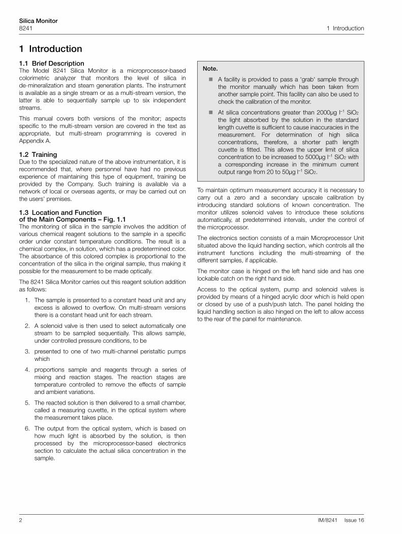
1 Introduction1.1 Brief DescriptionThe Model 8241 Silica Monitor is a microprocessor-basedcolorimetric analyzer that monitors the level of silica inde-mineralization and steam generation plants. The instrumentis available as a single stream or as a multi-stream version, thelatter is able to sequentially sample up to six independentstreams.
This manual covers both versions of the monitor; aspectsspecific to the multi-stream version are covered in the text asappropriate, but multi-stream programming is covered inAppendix A.
1.2 TrainingDue to the specialized nature of the above instrumentation, it isrecommended that, where personnel have had no previousexperience of maintaining this type of equipment, training beprovided by the Company. Such training is available via anetwork of local or overseas agents, or may be carried out onthe users' premises.
1.3 Location and Function of the Main Components – Fig. 1.1The monitoring of silica in the sample involves the addition ofvarious chemical reagent solutions to the sample in a specificorder under constant temperature conditions. The result is achemical complex, in solution, which has a predetermined color.The absorbance of this colored complex is proportional to theconcentration of the silica in the original sample, thus making itpossible for the measurement to be made optically.
The 8241 Silica Monitor carries out this reagent solution additionas follows:
1. The sample is presented to a constant head unit and anyexcess is allowed to overflow. On multi-stream versionsthere is a constant head unit for each stream.
2. A solenoid valve is then used to select automatically onestream to be sampled sequentially. This allows sample,under controlled pressure conditions, to be
3. presented to one of two multi-channel peristaltic pumpswhich
4. proportions sample and reagents through a series ofmixing and reaction stages. The reaction stages aretemperature controlled to remove the effects of sampleand ambient variations.
5. The reacted solution is then delivered to a small chamber,called a measuring cuvette, in the optical system wherethe measurement takes place.
6. The output from the optical system, which is based onhow much light is absorbed by the solution, is thenprocessed by the microprocessor-based electronicssection to calculate the actual silica concentration in thesample.
To maintain optimum measurement accuracy it is necessary tocarry out a zero and a secondary upscale calibration byintroducing standard solutions of known concentration. Themonitor utilizes solenoid valves to introduce these solutionsautomatically, at predetermined intervals, under the control ofthe microprocessor.
The electronics section consists of a main Microprocessor Unitsituated above the liquid handing section, which controls all theinstrument functions including the multi-streaming of thedifferent samples, if applicable.
The monitor case is hinged on the left hand side and has onelockable catch on the right hand side.
Access to the optical system, pump and solenoid valves isprovided by means of a hinged acrylic door which is held openor closed by use of a push/push latch. The panel holding theliquid handling section is also hinged on the left to allow accessto the rear of the panel for maintenance.
Note.
� A facility is provided to pass a 'grab' sample throughthe monitor manually which has been taken fromanother sample point. This facility can also be used tocheck the calibration of the monitor.
� At silica concentrations greater than 2000µg l–1 SiO2
the light absorbed by the solution in the standardlength cuvette is sufficient to cause inaccuracies in themeasurement. For determination of high silicaconcentrations, therefore, a shorter path lengthcuvette is fitted. This allows the upper limit of silicaconcentration to be increased to 5000µg l–1 SiO2 witha corresponding increase in the minimum currentoutput range from 20 to 50µg l–1 SiO2.

Silica Monitor8241 1 Introduction
IM/8241 Issue 16 3
Fig. 1.1 Main Components
Note. The arrangement of the constant head units for the multi-stream version is shown in Fig. 2.2B.
������������
� ���
� �
� ���
����
�������� ����
���������
���������
� ���
� ���
���
���
���
��
��
��
������
������������
� ���
� �
� ���
����
�������� ����
�
�
� ���!���"����#$$%�$&�!�������$'(%�)
*�+ �#
��%�'!��!���(" � !����
�+'!�"
��' ��+
����$�,�!���"����#$$%�$&�!�������$'(%�)
� ���!���&%$�!��$��%)
����!�����#�'-��.$(!�!��� (" � ����)
� ��� �������������������� ��� ��������
� �
/ �
�$�.��������''�!$�!�������!%$���'�'��!�$��&$��$-�'!� '�������!$������)
�$�.��������''�!$�!�����0(�#����#���.�'��!�$��&$��$-�'!� '���������#������)
��%�'!��!���("
�$���$�#�����'
��1�%� ''�"2���'�!�%%�%��$!$%
��#�����+��$���3��'�#�4
���!�#����!�$�5�$�,
����������
�$�!�"���!�#�%�����(�#�'�
�������%���
�$�'!��!����# ''�"2�+
�%��������&$�# ''�"2�+
�����%�6���!��.��$���3��'�#�4
��62(22��%
��" �������!
�(!�$&���" ����$�!��-�!��
�(" ��$!$%��
�(" ��$!$%��
�'!�����+��$���3��'�#�4
�%#�����+��$���3��'�#�4
�
�
������� ���������� �� ������������������������ �����!����� ��� ����������"
����'���7����-�!�������8�� �3�4
������-�!��
�(" ���7����-�!��
��2���9���#'
��'�%�-���#�'-��.�$(!�!$'���!����$����!$%�2�$�,')
/
�%$!��!������%!�3(�#�%���!�4

Silica Monitor8241 2 Installation
4 IM/8241 Issue 16
2 Installation2.1 AccessoriesThe accessories supplied are as follows:
4 x reagent containers1 x calibration solution container5 x solution container sealing caps1 x spares kit
2.2 LocationInstall in a clean, dry, well ventilated and vibration-free locationgiving easy access and where short sample lines can be used.Avoid rooms containing corrosive gases or vapors, e.g.chlorination equipment or chlorine gas cylinders. It is alsoadvisable to have adjacent drains near ground level, so that thewaste outlet from the monitor can be as short as possible,together with maximum fall. Power supplies should also beadjacent. Ambient temperature within the range 5°C to 40°C.
2.3 Mounting – Fig. 2.1See Fig. 2.1 for mounting procedure and enclosure dimensions.
2.4 Sampling RequirementsIn addition to being as close as possible to the monitor, thesampling point must provide a thoroughly mixed representativesample. The sample must also conform to the followingconditions:
1. Sample flowrates must be greater than 5ml min–1.
2. Sample temperature should be within the range 5°C to55°C.
3. Particles must be less than 10mg l–1 and the size must notexceed 60 microns without the sample filter being fitted.Above these levels it is essential that the filter supplied isfitted in both sample and emergency inlets.
Fig. 2.1 Mounting the Unit
Note.
� Mains (power supply) and signal cables are connected through cable glands directly into the electronic section.
� Sample and drain pipe work are brought in through the bottom of the case
��"��'�$�'����"")
�8�)� �8�)�
�:�)� �:�)�
;;8
������������
� ���
� �
� ���
����
�������� ����
�8<)�
;�
;88
�/8
��8=��$ ����.
�/8
:/8
<;���&
/�
��
<�
5%��,�!�*�+�$��';)�����;)8���
;)��""�����1��.��$��'
��8����%����&$%��$�,
��8���2��9���#���!%+
/��""����!%�'
�$-�%�$(�!��.� ���%'
��%,� !���-����('��.� !���#�"��'�$�'�'�$-�� ��� !��'&�.(%�)
�%������#� �(.� !����$��'���#�'�%�-� ��� !��� !$ � !-$'�%�-'72$�!'�!$� ��������.� �$&���""�2�!-����!��'�%�-����#���#�!���-���)
�!�%��!����+>�-�!��!�������$'(%����%�&(��+�'( $%!�#�.���'!�!���-���>�' $!�!�%$(.��('��.���'(�!�2���!$$�)
�$$,�!������$'(%��$�!$!�������$'(%����.�%�5%��,�!'�%�-')
� $!�!�%$(.���$-�%�&�1��.��$��'�&%$"�2��, ��!�)�"$�������$'(%��2�&$%��#%�����.��$-�%�&�1��.��$��')
�/:
�
�
�

Silica Monitor8241 2 Installation
IM/8241 Issue 16 5
2.5 Sample Connections – Fig. 2.2Connect inlet and outlet tubes as shown in Fig. 2.2A (singlestream) and Fig. 2.2B (multi-stream).
Note. A suitable 40 litre emergency sample container mustbe provided by the user. A suggested arrangement isshown in Fig. 4.2. Alternatively, a constant, independentsource may be used.
Note.
� Use tube of inert material, e.g. PVC.
� The inlet tube must incorporate a shut-off valve at itsup-stream end.
� Ensure that the drain outlet tube is short, has a free falland is vented to atmosphere as soon as possible.
Fig. 2.2 External Tube Connections
Note.
� To gain access to the constant head assembly follow steps 1, 2, 4 and 5 in Fig. 1.1.
� One constant head assembly is fitted for each sample inlet in multi-stream versions of the monitor. Fig. 2.2B shows sixsample inlets and six corresponding constant head assemblies.
��" ����(!��!'!$��$��!$%
�!%��"������!�$�����'
��" �������!��(2�'�?�!%��"'��>�����#���%�' ��!����+
�������%����(2�'
�!%��"������!�$�����'
�(!�$&���" ����$�!��-�!���'
�$�'!��!����# ''�"2�+
��" ����(!��!�!$��$��!$%
��" �������!��(2�'�?�!%��"'�/>�����#�;�%�' ��!����+
#�$��� ���������%�&� ����� �
'�$�&� ��������� ����(����)�����%�&� ��� ��*����+ ���
���#�!���%��.��!�!(2�'�!�%$(.��!��.%$""�!>��!�!�����&!����#�%��%��$%��%$&�!�����'�>�&%$"�2����!�)���!�!��"�!$!���� %$ %��!���$����!$%'�3%�#�!$�%�#>��#�'$�$�4)
�('��!���#%����!(2��3@�""���4$�!$�!����1!�%����!(2���$'��$����!$%)
�('��!���'�" �������!�!(2��3;�""���4$�!$�!����$�'!��!����#�'�" �������!�!(2��$'���$����!$%�3!���'"����%�$&�!���!-$!(2���$����!$%'4)
�('��!���������#%����!(2��3@�""���4�$�!$!����$�'!��!����#�������#%����!(2���$'��$����!$%�3!�����%.�%�$&�!���!-$�!(2��$����!$%'4)
�
�
�
/

Silica Monitor8241 2 Installation
6 IM/8241 Issue 16
2.6 External Electrical Connections – Figs. 2.3 to 2.5
The external electrical connections are in the electronic section,behind the hinged cover and beneath the RFI screen – seeFig. 2.3. The cables are passed through the cable glands on theright hand side on the monitor case and connected as follows:
� Mains input (power supply) – 115V (110 to 120V) or230V (220 to 240V). The mains voltage is selected usingthe voltage selector – Fig. 2.3.
� Single-Stream – CURRENT OUTPUT 1 and 2 – twoindependent current outputs for external recording orcontrol.
Multi-Stream – CURRENT OUTPUT 1 to 6 – one currentoutput per stream.
The setting of the range of the current output is covered onProgramming Page 4 (see Section 6.5, page 24).
� Single-Stream:RELAY 1 and 2–two 'Concentration' alarms relays.RELAY 3–'Out of Sample' alarm relay.
Multi-Stream:RELAYS 1 to 6–one relay per stream configurable as 'Concentration' or 'Out Of Sample' alarms relays.
The 'Out of Sample' alarm relay can be used as a remoteindication.
� CALIBRATION – remote calibration mode indicationalarm relay. This indicates when the instrument is off-lineduring a calibration – see Section 7, page 27.
� OUT OF SERVICE – remote instrument 'Out of Service'indication alarm relay. This indicates that the monitorreadings are suspect and it is in need of attention – seeSection 8.4, page 34.
� SERIAL – optional serial interface (see supplementaryinstruction manual for details).
Warning.
� Although certain instruments are fitted with internalfuse protection, a suitably rated external protectiondevice, e.g. a 3A fuse or miniature circuit breaker(MCB), must also be fitted by the installer.
� Before making any connections, ensure that thepower supply, any high voltage-operated controlcircuits, high common mode voltages, includingexternally powered alarm circuits, are switched off.
� The power supply earth (ground) must be connectedto ensure safety to personnel, reduction of effects ofradio frequency interference (RFI) and correctoperation of the power supply interference filter.
Caution. Slacken the terminal screws fully before makingconnections.
Note. Because the current output is isolated, the negativeterminal MUST be connected to earth (ground) if connectingto the isolated input of another device.
Note. All relays have voltage-free single pole change overcontacts.
Fig. 2.3 Mains Input Connector Block and Voltage Selector Locations
�$!��%2$�%#
����'��� (!�3 $-�%�'( �+4�$����!$%�5�$�,
�$-�%��( �+����!3���4
$�!�.�������!$%3����$%���84
�$����!$%�5�$�,'3������.')��)/�A��)�4
�
�
�
��8��
����%���
Note.
� To access theconnector blocks firstundo the 10 fixingscrews and removethe R.F. screen.
� Replace and securethe R.F. screen beforeoperating thisequipment.

Silica Monitor8241 2 Installation
IM/8241 Issue 16 7
Fig. 2.4 Electrical Connections – Single Stream
�$-�%��( �+��� (!
��%"��
��%"��
�$����!%�!�$� ��%"'
�
�
�
� ���
�����
�� B
���� B
��� ��5 ����
������
��
���
�7���?C
�7���7�
�D6�DCD6DC
8
E�(!�$&���" ��F���#���!�$� ��%"����+
�$!��'�#
�"$!��G����2%�!�$���$#�G��#���!�$�� ��%"����+
�"$!��G�(!�$&���%����G��#���!�$�� ��%"����+
�(%%��!��7�'�����#���?H!-$��#� ��#��!��(%%��!�$(! (!'&$%��1!�%����%��$%#��.�$%�$�!%$�
�$!��'�#
� !�$������%������!�%&����?'���'( ��"��!�%+���'!%(�!�$�"��(���&$%�#�!���'�
�� �
�7���7�
�� B
���7���7�
�� B
�/�� B
���� B
�;
�7���7�
�7���7�
�7���7�
�7���7�
�7���7�
�����
�����
�7���
�7����7��/
?C?C?C
?C?C
�7����7��;
C6
C
C
C
6
6
6
Fig. 2.5 Electrical Connections – Multi-Stream
�$-�%��( �+��� (!
�!%��"��
�!%��"��
�!%��"��
�!%��"�/
�!%��"��
�!%��"�;
�$�&�.(%�2����'�$����!%�!�$��$%E�(!�$&���" ��F ��%"����+
�"$!��G����2%�!�$���$#�G��#���!�$�� ��%"����+
�"$!��G�(!�$&���%����G��#���!�$�� ��%"����+
�!%��"��
�!%��"��
�!%��"��
�!%��"�/
�!%��"��
�!%��"�;
�!%��"��(%%��!�(! (!'�?�$���(%%��!�$(! (! �%�'!%��"
� !�$������%������!�%&����?'���'( ��"��!�%+���'!%(�!�$�"��(���&$%�#�!���'
�
�
�
� ���
�����
�� B
���� B
��� ��5 ����
������
��
���
�7���?C
�7���7�
�D6�DCD6DC
8 ��
� �
�7���7�
�� B
���7���7�
�� B
�/�� B
���� B
�;
�7���7�
�7���7�
�7���7�
�7���7�
�7���7�
�����
�����
�7���
�7����7��/
?C?C?C
?C?C
�7����7��;
C6
C
C
C
6
6
6

Silica Monitor8241 2 Installation
8 IM/8241 Issue 16
2.7 Relay Contact Protection and Interference Suppression – Fig. 2.6If the relays are used to switch loads on or off the relay contactscan become eroded due to arcing. Arcing also produces RFIwhich can cause instrument malfunctions and incorrectreadings. To minimize the effects of RFI, arc suppressioncomponents are required; these are resistor/capacitor networksfor AC applications, or diodes for DC applications. Thesecomponents can be connected either across the load or directlyacross the relay contacts.
For AC applications the value of the resistor/capacitor networkdepends on the load current and inductance that is switched.Initially fit a 100R/0.022µF RC suppressor unit (part no. B9303)as shown in Fig. 2.6A. If the instrument malfunctions the value ofthe RC network is too low for suppression and an alternativevalue must be used. If the correct RC suppressor unit cannot beobtained, contact the manufacturer of the switched device fordetails of the RC unit required.
For DC applications fit a diode as shown in Fig. 2.6B. Forgeneral applications use an alternative IN5406 type (600V peakinverse voltage at 3A – part no. B7363).
Note. For reliable switching the minimum voltage must begreater than 12V and the minimum current greater than100mA.
Fig. 2.6 Relay Contact Protection
�� � ��
�1!�%�������( �+
, $
���+��$�!��!'
�$�#
��$#�
�� � ��
�1!�%��� ���( �+
- .
���+��$�!��!'
&/
�$�#
#�$�#&�#��������� �
'�$�0&�#��������� �

Silica Monitor8241 3 Setting Up
IM/8241 Issue 16 9
3 Setting Up
1. Ensure that all external electrical and plumbingconnections have been made correctly.
2. Fill reagent and standard solution bottles (see Section 8.1,page 28 for details of these solutions).
3. Connect the reagent float switch to the plug (Fig. 3.1)routing the lead through the far left hand grommeted holein the bottom of the enclosure.
4. Connect the electrical supply and switch on.
5. Verify that there is an adequate supply of sample to themonitor constant head unit.
6. Fit the cuvette drain tube into the pinch valve. Press in thecentral plunger and ensure that the tube is fully insertedinto the valve. This ensures that no leakage from thecuvette occurs.
7. Fit the pressure plate platen on the peristaltic pumps (seeSection 8.2.6, page 31) and switch the pumps on with theswitch on the side of the monitor. Note that the peristalticpumps rotate and check that sample and reagents arebeing drawn into the monitor by observing the progress ofany small bubbles present in the inlet tubes.
8. Run the monitor for at least one hour to allow the solutionsto be pumped into the system and to purge the air fromthe pipework. Check for any leaks around the pipeconnections and rectify as necessary.
9. Set the following parameters to YES using ProgrammingPage 2.1:
Five-Weekly System FlushFive-Weekly Solution ReplacementDefault Calibration Parameters.
10. If having not already done so, energize the secondary CALvalve (see Programming Page 2.3) and leave for 15minutes. Adjust the reading on scale with the and
switches and run the monitor for one to two hours topurge the old solution and assess stability.
11. If the monitor exhibits good stability, i.e. ±2% of reading,carry out a two-point BASELINE calibration – seeProgramming Page 2.3.
12. Check the condition of the sample filters and replace themif necessary. Ensure that new filters are fitted correctly bytaking note of the flow directions indicated on the filterbodies.
Note. Before proceeding any further, ensure that the HOLDswitch is ON; all other switches are set to OFF on the righthand side of the electronics unit – see Fig. 1.1.
Note. The temperature controlled reaction block andoptical block require up to one hour to reach thenormal control temperature. During this time,'Temperature Stabilizing' is indicated on ProgrammingPage 1.0 – see Section 6, page 19 (or Appendix A formulti-stream programming). Any calibrations areprevented by the microprocessor during this time.
Note. If the monitor has not been in use for a longperiod, the 're-wetting' process of the system can bespeeded up by introducing the chemical rinse solutionfor a period of 30 to 60 minutes – see Section 8.2.4,page 30.
Note. Before proceeding to the next step,multi-stream users must select single stream mode asdescribed in Section 4.3.
Fig. 3.1 Reagent Float Switch Connector
��.��!��$�!��-�!���$����!$%
�$���$�#�����'
����
�(!�$&���" ����$�!��-�!��
�(" ��$!$%

Silica Monitor8241 4 Liquid Handling Section
10 IM/8241 Issue 16
4 Liquid Handling Section4.1 Principle of Operation – Fig. 4.1The chemical method used in the monitor utilizes the reactionbetween silicate species in the sample, acid and molybdatereagents, to form yellow molybdosilicic acid complex. The acidconditions are chosen so that specifically beta-molybdosilicicacid is produced which excludes interference from other formsof the acid complex. To improve the sensitivity of the methodthe yellow acid is reduced to the blue form which is measuredcolorimetrically in the optical system.
The sequence of events is:
1. Sulfuric acid (1st acid reagent) is added to the sample toreduce the pH to a value between 1.4 to 1.8pH.
2. Ammonium molybdate is added to the acidified sample.
3. The solution enters the first reaction coil in thetemperature controlled block (providing a two minutedelay) where the yellow beta-molybdosilicic acid isdeveloped.
4. Sulfuric acid plus citric acid (2nd acid reagent) is addedbefore the solution enters the second reaction coil in thetemperature controlled block (providing a two minutedelay) to reduce the pH further to a value between 0.8 to1.0pH. This is the pH value required to stop furtherdevelopment of the silica and to provide the conditions forthe next reaction (reduction) to take place.
In applications where the sample contains phosphate, thecitric acid concentration is increased to destroy anyphosphate complexes which would augment the colordeveloped in the next stage.
5. The reduction solution is added before the solution entersthe third reaction coil in the temperature controlled block(providing a one minute delay) reducing the yellowcomplex to the blue form.
6. The fully developed solution passes to the measuringcuvette in the optical system where the intensity of thecolor, which is proportional to the original silicaconcentration, is measured.
7. During the automatic zero calibration the monitorgenerates a zero solution by diverting the sample to apoint where the second acid solution is added. The pH atthis point is too low to allow the silica-molybdate reactionto take place, so the solution of zero silica concentration isproduced. In the zero calibration the system allows silicain the first acid and molybdate solutions to be developed.A secondary upscale calibration is achieved by theautomatic introduction of a standard solution of a knownvalue.
4.2 General Operation – Figs 4.2 and 4.3The sample enters the constant head unit situated at the bottomof the instrument case – see Fig. 4.2A for single stream andFig. 4.2B for multi-stream. The constant head units are fittedwith an 'Out of Sample' switch. This switch is used by themicroprocessor, in the appropriate situation, to instigate the'Out of Service' alarm and to energize the emergency samplevalve. This valve introduces sample from an alternative supply tomaintain the monitor operation when the sample has been lost.This avoids potential problems caused when the monitor is runwithout a sample for long periods.
For the multistream version, each sample is presented toindividual constant head units each of which is fitted with an'Out of Sample' switch (see Fig. 4.2B). Solenoid valves, MSV 1to 6, attached to each constant head unit are then used toselect each stream to be sampled. The emergency sample valveis energized when all sample streams are lost or de-selected.
The sample is drawn off from the selected stream by onechannel of the peristaltic pump (P1) via the pre-heating coil –see Fig. 4.2B. The purpose of this coil is to pre-heat the sampleprior to the reaction taking place. Any air bubbles which form inthe sample are removed by the de-gassing block and pumpedto drain by another channel of (P1). This is necessary to reducethe effect of air bubbles in the sample which will give variablereagent mixing resulting in noisy readings on the display.
Note. Fitted in the sample lines are disposable samplefilters. These are necessary to protect the liquid handlingsystem from blockages due to solids in the sample.
Fig. 4.1 Chemical Schematic
��%'!�"�1��.�'!�.� ���$�#�"�1��.�'!�.� ���%#�"�1��.�'!�.�
�-$�"��(!�#���+
�-$�"��(!�#���+
����"��(!�#���+
��" ��� �!��#(%��.� (!$?I�%$
��%'!� ��# �$�+2#�!� ���$�#� ��# '�$%2��� ��#3�#(�!�$���$�(!�$�4
�)/�!$��)< �� %$��#��. %$#(�!�$��$&
+���$-���"$�+2#$'����������#�%$#(�!�$��$&�2�(�"$�+2#$'���������#
�$" ��1
8)<�!$��)8 �� %$��#��.%�#(�!�$���$�#�!�$�'��#�!$�'!$ �&$%"�!�$�$&�+���$-��$" ��1
���!�#���" ��!$��(��!!�

Silica Monitor8241 4 Liquid Handling Section
IM/8241 Issue 16 11
The 1st acid and the ammonium molybdate solutions, deliveredvia two channels on the peristaltic pump (P2) are then added tothe sample in the static mixer block (M1) before passing throughthe 1st heated delay coil where the first reaction takes place.
The 2nd acid, via P2 is added to the sample before entering thedynamic mixer (M2) and then passes through the 2nd heateddelay coil.
Fig. 4.2 Flow Schematic – Sample Inlet
#�$1�� ���������%
'�$1(����)�����%
�(!�$&���" ����$�!��-�!��
�$�'!��!���#����!
���%&�$-�%���
��" ������!
��3'�����.)�/)�4
�%��� �"�%.���+���" ���$�!����%
��" ��
5�(�
��" �����!�%'
�(!�$&���" ����$�!��-�!��
�$�'!��!���#����!'
���%&�$-�%��� ��" ��
����!
��
�%��� �"�%.���+���" ���$�!����%
5�(�
��" �����!�%'
���������
;�/���
� �!$�'�1��" ������!
�!%��"'

Silica Monitor8241 4 Liquid Handling Section
12 IM/8241 Issue 16
Fig. 4.3 Flow Schematic of Chemical Section
��
��%�'!��!��
�("
��
�+��"
����1�%
5�$�,
��6.�''��.
5�$�,
��"
��
&%$"
�$�'!��!
���#
���! �"
�%.���+
��"
��
3����%4
���$�#�%+
�!��#�%#
�$�(!�$�
3B���$-4
�%�6���!��.��$��
�%#�����+��$��
���!�#
���!�$�
5�$�,
���%&�$-
�%���
��
��
�(��!!�
�%���
�%��������
�(��!!�
��!7�%���
�%�5(22��
��!�
�%���
��#�����+��$��
�'!��
���+��$��
��%�'!��!��
�("
��
� !������+'!�"
���!�%
���!�$�
5�$�,
���!�%
��#
��#
3�%��.�4
�#(�!�$�
35%$-�4
���!�#
��"
��
�$�+2#�!�
3�$��!4
�'! � ��#
3�#4
(!$
I�%$
����
��
��"
��� �!��#(%��.
(!$�I�%$
��
��
�!�!��
��1�%
5�$�,
�%��.�
�$��!
�#
5%$-�
5�(�
5�(�
5�(�
5�(�
5�(�

Silica Monitor8241 4 Liquid Handling Section
IM/8241 Issue 16 13
The solution then passes into the dynamic mixer (M3) where thereduction reagent solution is added via P1.
The resultant solution is then passed through the 3rd heateddelay coil before being presented to the measuring cuvette.
During an AUTO ZERO, solenoid valve SV3 is used to divert thesample from mixer block M1 to M2. Solenoid valve SV2 is usedto introduce the secondary standard solution. In the event of aloss of sample, SV1 is used to introduce an emergency sampleto prevent the undiluted reagents fouling in the system plumbingtubing.
The sample pre-heater coil and the three reaction coils aremounted in a single acrylic block. This block is heated using asmall 24V cartridge heater and controlled using a PT100temperature sensor. This optimizes the chemical reaction timeand removes the effect of ambient and sample temperaturechanges.
The coils are made from PTFE and do not normally require anymaintenance except for the 5-weekly system flush – see Section8.2.2, page 30.
4.3 Multi-Stream OperationBetween two and six streams can be fitted to the multi-streamversion of the monitor. The front panel controls remain the sameon all versions.
The monitor samples the streams in the sequence specified onProgramming Page 3.3 (see Appendix A on page 42). Thestream sampling period, i.e. the duration the monitor spends oneach stream, is normally set to 12 minutes, although the upscaleand downscale times can be set independently by the user –see Programming Page 4.1. However, the reading, taken after a
further six minutes, is used to update the display and currentoutput for that particular stream. This takes advantage of theeight minutes 'dead' time of the monitor in reducing the overallsampling period – see Fig. 4.4.
The reading for that stream is then held until that stream is againsampled and updated. This includes 'Loss of Sample' andde-selection of the stream.
The stream sequence would be normally set to sample eachstream in turn, i.e. on a three stream version this would be set to1, 2, 3. However, greater priority could be given to a particularstream (e.g. stream 1) by programming the sequence 1, 2, 1, 3or 1, 1, 1, 2, 3 etc.
Front panel stream LEDs provide status information on eachstream as follows:
Green Stream selected.Flashing green Sample currently being sampled.Red Sample lost on stream.Not illuminated Stream de-selected or not fitted.
If the stream is unavailable throughout the sampling period themonitor selects the next stream in the sequence. The redstream lamp remains on until the stream is sampled again; if thestream has been reinstated, the LED changes to green and thedisplay is updated as normal.
Single Stream Mode for Maintenance
To carry out any maintenance it is necessary to switch to asingle stream provided that a stream is available. If not, asolution could be introduced via the SECONDARY CAL valve(energized on Programming Page 2.2 – see Appendix A onpage 42). Single stream mode is initiated by selecting onestream on Programming Page 3.3, Appendix A. This stops themulti-stream sequencing and enables the display and thecurrent output to respond to changes on each drain/fill cycle.This mode is used to check the basic performance of themonitor, such as response or drift, without waiting for thenormal stream update.
Selecting more than one stream puts the monitor intomulti-stream operation.
Note. A dynamic mixer consists of a small stirrer sited in achamber in the mixer block and is magnetically coupled to asmall electric motor.
Fig. 4.4 Multi-Stream Timing
���#���"��<�"��
��" ���.���!�%����$"��������"��
� #�!����"�;�"��
�!%��"���$���$�#������� ��
�!%��"���$���$�#������� ��
�!%��"���$���$�#������� ��
�!%��"�/�$���$�#������� ��
��#��.���,���&$%�!%��"��
��#��.���,���&$%�!%��"��
��#��.���,���&$%�!%��"��
���#���"��<�"��
Silica Monitor8241 4 Liquid Handling Section
14 IM/8241 Issue 16
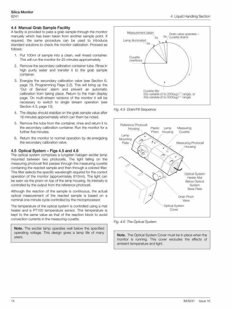
4.4 Manual Grab Sample FacilityA facility is provided to pass a grab sample through the monitormanually which has been taken from another sample point. Ifrequired, the same procedure can be used to introducestandard solutions to check the monitor calibration. Proceed asfollows:
1. Put 100ml of sample into a clean, well rinsed container.This will run the monitor for 25 minutes approximately.
2. Remove the secondary calibration container tube. Rinse inhigh purity water and transfer it to the grab samplecontainer.
3. Energize the secondary calibration valve (see Section 6,page 19, Programming Page 2.2). This will bring up the'Out of Service' alarm and prevent an automaticcalibration from taking place. Return to the main displaypage. On multi-stream versions of the monitor it will benecessary to switch to single stream operation (seeSection 4.3, page 13).
4. The display should stabilize on the grab sample value after16 minutes approximately which can them be noted.
5. Remove the tube from the container, rinse and return it tothe secondary calibration container. Run the monitor for afurther five minutes.
6. Return the monitor to normal operation by de-energizingthe secondary calibration valve.
4.5 Optical System – Figs 4.5 and 4.6The optical system comprises a tungsten halogen exciter lampmounted between two photocells. The light falling on themeasuring photocell first passes through the measuring cuvettecontaining the reacted sample and then through a colored filter.This filter selects the specific wavelength required for the correctoperation of the monitor (approximately 810nm). The light canbe seen via the prism on top of the lamp housing. Its intensity iscontrolled by the output from the reference photocell.
Although the reaction of the sample is continuous, the actualoptical measurement of the reacted sample is based on anominal one-minute cycle controlled by the microprocessor.
The temperature of the optical system is controlled using a matheater and a PT100 temperature sensor. This temperature iskept to the same value as that of the reaction block to avoidconvection currents in the measuring cuvette.
Note. The exciter lamp operates well below the specifiedoperating voltage. This design gives a lamp life of manyyears.
Fig. 4.5 Drain/Fill Sequence
Fig. 4.6 The Optical System
Note. The Optical System Cover must be in place when themonitor is running. This cover excludes the effects ofambient temperature and light.
�(��!!�$��%&�$-'
��" ����("���!�#
���'(%�"��!�!�,�� �%����������$ �%�!�'�?�(��!!��#%���'
�(��!!��&���'J��'���%��2���38�!$��888K.��?��%��.�4>�$%/8'���%��2���38�!$��888K.��?��%��.�4
�'
�'/'
��" �$(�!��.���!�
� !������+'!�"���!�%���!
5��$-�� !�����+'!�"
5�'�����!�
���'(%��.���$!$�����$('��.
���'(%��.�(��!!�
��" �$('��.
�&�%�������$!$�����$('��.
�%�������������
� !������+'!�"�$��%
���'!���%�'"

Silica Monitor8241 5 Electronics Section
IM/8241 Issue 16 15
5 Electronics Section5.1 Front Panel Controls – Figs. 5.1 and 5.2The program controls comprises five tactile membraneswitches. In normal operation the switches are used to view themeasured variable, the concentration alarm values, diagnosticsand status information. Access to the programming andcalibration pages are protected by customer programmablesecurity codes.
When programming, the switches are used to sequencethrough a programming procedure as detailed in Section 6(Single Stream) or Appendix A (Multi-stream). The procedure isset out in programming pages for Input, Current Output, Alarms,Real Time Clock and Monitor Calibration. Each program pagecontains the program functions, the values or parameters ofwhich are all programmable.
Switch functions are described in Fig. 5.1.
Three other switches are situated on the side of the electronicsection – see Fig. 1.1. Their functions are as follows:
5.2 DisplayThe monitor display panel indicates the solution concentrationand provides user information during setting up and in normaloperation.
5.3 LED Indicators
Single Stream
Multi-Stream
These indicators are used in association with external alarmrelay outputs except for the multi-stream version where theRelays 1 to 6 can be configured as remote stream 'Out ofSample' or concentration alarm indication – see Fig. 2.5 andFig. 2.6.
Mains ON/OFF Used to isolate the mains (power) supplyfrom the instrument.
Pump ON/OFF Used to switch the pumps on and off duringmaintenance.
HOLD ON/OFF Used to hold the concentration alarms,activate the 'Out of Service' relay and inhibitany timed automatic calibrations duringmaintenance.
Note. A flashing display indicates that the value is out ofrange for that particular parameter.
Out of Service Indicates that the monitor out of servicealarmis active, the source is indicated onProgramming Page 1.0 – see Section 6,page 19.
Cal Indicates when a calibration sequence istaking place.
Hold Indicates that the HOLD switch has beenswitched to 'HOLD' during servicing. Thisholds the current concentration alarm statesand activates the 'Out of Service' alarm relayand inhibits timed automatic calibration.
Alarm 1,2 Used to indicate a concentration alarm state(either high or low).
Out of sample Indicates that sample has been lost.
Streams 1 to 6 These are two color red/green LEDindicators. A continuous green indicationshows the stream(s) selected, a flashinggreen indication shows the stream which iscurrently being sampled and a red indicationsignifies an 'Out of Sample' alarm on thestream indicated.
Alarms 1 to 6 Used to indicate a concentration alarm state(either high or low).

Silica Monitor8241 5 Electronics Section
16 IM/8241 Issue 16
Fig. 5.1 Front Panel Controls – Single Stream
Note. Continued pressure on the or switches causes the rate of change of the displayed value to increase. To makesmall adjustments, operate the switches momentarily.
Fig. 5.2 Front Panel Controls – Multi-Stream
������������ � � ����
� ��� � ��� �������� ����
��.�� #������?��'�#>�����!���'��(%�!+�$#�>�&$%��#������.�!�%$(.��!���"��� %$.%�"� �.�'>��).)�!$��#������&%$"�%$.%�"���.��/)8!$��)8)
��'�7�$-�%�?��'�#�&$%�����.��.�� �%�"�!�%����(����$'���-�!��!���(%'$%�$%�'!� ��.�( �$%�#$-�!�%$(.����'����!�$��$&� �%�"�!�%'� ����2���!$��� �%!��(��%�&(��!�$�)
�(%'$%�?��'�#�!$�'!� !�%$(.��!��� �%�"�!�%'-�!������ �.�)����'����!�#����(�'�&��'�)
�(2� �.�� #������?��'�#�&$%�#������.�!�%$(.��'(2� �.�'>��).)!$��#������&%$"��%$.%�"���.���)�!$��)/)
��0(�#��%+'!�����' ��+
������#���!$%')�������!�$���)��&$%�&(��!�$�')
������������ � � ����
��� �
� �
� � � / � ;
��0(�#��%+'!�����' ��+
������#���!$%')�������!�$���)��&$%�&(��!�$�')
������.)��)��&$%�#�'�%� !�$��$&�,�+�&(��!�$�')

Silica Monitor8241 5 Electronics Section
IM/8241 Issue 16 17
5.4 Microprocessor Unit – Figs. 5.3 and 5.4The electronic section comprises six main circuit boards whichcarry out the following functions:
Motherboard Comprises the user terminations,alarm relays and sockets for the fourplug-in boards.
Cuvette Input Board Processes the signals from the twophotocells and controls the lampbrightness.
Microprocessor Board The heart of the electronics sectionwhich controls all aspects of themonitor.
Drive Board Provides outputs to drive internalfunctions, i.e. stream selection,calibration value, pump motor andheater control.
Output Board Provides current, alarm outputs and, iffitted, the serial interface.
Display Board Connected to the microprocessorboard by a ribbon cable and providesdisplay and keypad functions.
Fig. 5.3 Microprocessor Unit
�$!��%2$�%# ����'�3�$-�%��( �+4��� (!�$����!$%�5�$�,
�(! (!5$�%#
�%���5$�%#
�$-�%��( �+���!�3���4
$�!�.������!$%
�22$����2��!$����' ��+���#
*�+ �#
���%$ %$��''$%5$�%#
�(��!!���� (!5$�%#
�$����!$%5�$�,'
3������.')�)��A��);4
����%���

Silica Monitor8241 5 Electronics Section
18 IM/8241 Issue 16
Fig. 5.4 Electronics Section Schematic
�(%%��!
�(! (!'
� � � / � ; � � � / � ;
���+'
����'�3�
$-�%4
�� (!
�!%��"
��%"
���+'
����2%�!�$���$#�
�(!�$&��
�%����
��%������!�%&���
�$-
$�!�.�
�( ���'
�$-
�%�( �+
�(! (!
5$�%#
����>��("
>���#
���!�%��
%����5$�%#
���%$ %$��''$%�5
$�%#
�(��!!�
�� (!
5$�%#
�("
��7���
�-�!��
����
�-�!��
��" ��%���
��$!$��������')
��$!$������&)
���88��
���88��
������������/�������;
�(!�$&
��"
��
�(!�$&���.��!
�!%��"
�$���$�#'
�%���
���$�#�%+
(!$�I�%$
�"�%.���+
��' ��+7*�+ �#
5$�%#
�(" ��
�(" ��
�!�%%�%
���!�%��
���!�%��
������������/�������;
� ���$�
���3� 3�4���84
��%!�
����'
��7�&&
�-�!��

Silica Monitor8241 6 Single Stream Programming
IM/8241 Issue 16 19
6 Single Stream ProgrammingIn normal operation (Operating Pages 0 and 1) the display givesindication of the units of measurement, diagnostics, calibrationinformation and time. Selection is made by means of the and switches.
Operation of the switch enables a series of 'programming'pages to be displayed. Unauthorized entries to these pages areinhibited by a four-digit security code which is displayedimmediately after the page header.
Values displayed in Operating Pages 0 and 1 are for viewingonly and cannot be altered by the operator. Displayed values onsubsequent pages indicated by x's can be altered by means ofthe and switches. Options such as Yes/No orHigh/Low are also selected using these switches. Passing ontothe next parameter, or exiting from the page, automaticallyenters the new value into memory.
Programming information for users of multi-stream monitors iscontained in Appendix A.��
����
��
����
����
����
����
����
����
�� �
����
�
����
����
����
����
����
����
����
���
���
����
����
����
����
����
!"
#"#�
�� $
%&'�
�()�
�(*�
+,��
-���
.+/�
����
�0�1
����
�1'�
2�33
��3�
�1��
-��(
���
&�+
���3
�.1�
��+(
����
��
���
��"
#�!
��#
���
����
����
����
����
���
��4
����
����
����
+,�2
�1��
�''&
����
������
���+
(�1+
3���
�0�1
��&1
����
����
��5�
����
����
����
��'0
3�*�
&(��
'���
��6&
(��'
7 3��
1�'�
�&0�
'�8&
1��*
�8+$
����
����
�
���
��"
#�!
��#
���
����
����
����
����
���
��9
����
�(��
1�'�
8&1�
�*�8
+$��
����
�
�$� �.��/
��" �#��"��"#:�!� "�#������������ ���4�9
#����;�2��<3*�'�1/�8����������
#����*��13*�'�1/�8���������������
���+(��+1��(�'�1/�8�
�������"#:�!� "�#����������������� ���4�4
�0��8�3�'*'�������0�1��&1��������5�
!��8��+(�.3+8<����0�1��&1��������5�
���������������=�1+�+,,'���������6&(��'7
����������3�.1���+(�,�8�+1�������
�������������������������������������
������������������������������������
�������"#:�!� "�#����������������� ���4��
������������&(��'������������
#���� ��=�!��� ������������
��'�� ��=�!��� ������������
������#��������� ������������
��������'������� ������������
������������ �">! "�#������������ ������
���"(���������(&�3� ��=�!������#�
����������� ��'+3&��+(�/�3&������6&(��'7
���3�.1���+(�$�������������������������
������3�.1���+(���������������������
��������� ��=�!��,1�?&�(8*�����
��=�!�'�.��2��(������� ������
B��
����
�� �
����
!���
@�!�
���A
�#�
����
���
��B
����
����
����
����
!��$
�()�
����
���6
&(��
'7�
����
+��(
$�+,
�'�?
&�(8
����
����
���(
����
����
����
=�1+
�+,,
'���
����
���6
&(��
'7��
����
�3�.
1���
+(�,
�8�+
1���
����
����#� !��� �">! "�#���A�#���� ���������;
��������������������!��$�()������6&(��7
������������+�8+�0�('���+(��������(
����� .+1������8�3�.1���+('���#�
��=�!����A�#�������������� �����C
�������������������!��$�()������6&(��'7
�����������+�8+�0�('���+(��������(
����� .+1�� =�8�3�.1���+('���#�
�����������������#� !��� ����#�
�� "#�# #��� #��� �">! "�#�������� �����9
�����(��1�'�8&1��*�8+$�������
�����!�"#��� "#�# #�������������� �����4
������������;� ��<3*�0�0��1�('����#�
��;� ��<3*�'+3&��+(�1�03�8���(����#�
����������������� ((&�3�'�1/�8����#�
���,�&3��8�3�.1���+(�0�1�����1'���#�
3��1����(��(�(8��'�8&1��*�8+$���������
������!�"#��� "#�# #������������� ������
��������(�1)�'�� ��=�!��/�3/����#�
����(�1)�'������#� !��� ��/�3/����#�
�(�1)�'�����!��#���� �����/�3/����#�
�������2��8-�3��0�+(�8+(��(&+&'���#�
D)�3
�� � ��3�
8���
�����
��
B��
���
���

Silica Monitor8241 6 Single Stream Programming
20 IM/8241 Issue 16
����
�#�!
�� �
���#
:"�
! "
�#��
����
����
���
;�4
����
3�1
��,�
�3'�
,���
����
����
���
3�1�
�$�3
�*��
����
��(
�� 3
�1��
-*'�
�1�'
�'��
����
E
����
� !
��!�
� ��
��
����
����
����
����
� ��
�;�9
���
4��(
�.3�
$���
#���
4�'
��0+
�(��
����
��6&
(��'
7��
�� 4
��8�
�+(�
����
��
� ��
�(�.
3�$�
��#�
�� �
�'��
0+�(
����
����
6&(�
�'7
����
���
8��+
(���
��
������!!�#
��
��
����
����
����
�� �
��C�
9
���&�0&��1�()�
�4��
�9��
+���
���6
&(��
'7��3�.1���+(�-+
3$��
�#�
���&�0&��1�()�
����
�9��
+���
���6
&(��
'7��3�.1���+(�-+
3$��
�#�
������&�0&���*
0���
����
�+��
���
������'��+&�0
&���
�#�
����: ��!����"#������������������ ���B�9
���(��1�,�8�+1*�'����()'
�����������'�8&1��*�8+$��������
�����: ��!����"#����������������� ���B�4
� !#"#����-�'��0�1�����1'��1��,�8�+1*
�'����($�'-+&3$�(+��(+1��33*�1�?&�1�
��$%&'���(���-�*�8�(�+(3*�.��'���&0��,
��-��(�8�''�1*��?&�0��(���'��/��3�.3��
����#���!������ "�����#��"#����
����! "�#�� # ��
��������!"� ��� �">! "�#���������� ���B��
����!��$�"���F�1+�G�@��������
����!��$�"���'0�(�H�@��������
�����!�,�"���F�1+�G�@��������
�����!�,�"���'0�(�H�@��������
��������!"� ��� �">! "�#���������� ���B��
�����������������!��$�()������6&(��'7
������0��3�)(��(��@�1��$����������@+3�'
������0��3�)(��(��@�1�,�����������@+3�'
� 3��1�,�8�+1*�'����()'
����������'�8&1��*�8+$���������
��������!"� ��� �">! "�#���������� ���B�C
��0�1��&1��8-�(4�F�1+�499
����������
��0�1��&1��8-�(4�'0�(�4;9
����������
��0�1��&1��8-�(��F�1+�499
����������
��0�1��&1��8-�(��'0�(�4;9
����������
��������!"� ��� �">! "�#���������� ���B�;
�����������&11�(��+&�0&��4�C�
�����������&11�(��+&�0&��4��9�
�����������&11�(��+&�0&����C�
�����������&11�(��+&�0&�����9�
������"#�!��#�"�"#�������������� ���B�B
�����'&1�$�/�1��.3��,�3��1����#
�����������&��+&�0&��1�()����9G����
�������&/�����,�33�()������������'
������������ ��=�!���������������(
����#� !��� �">! "�#��������������(
���!�8+/�1*�+(�'��03���������������(
���� �">! "�#� � !��������������� ���B�I
�=�1+�+,,'���1�()����9�9H�G����6&(��'7
���3�,�8�+1�1�()�����4�9H�G�����
�%$"
���.���
�$���
�.��8
No
te.
�Th
e se
curit
y co
de o
n P
rogr
amm
ing
Pag
e 6.
0 is
set
at
the
fact
ory
to p
reve
ntal
tera
tions
by
unqu
alifi
ed p
erso
nnel
. The
sec
urity
cod
e fo
r thi
s pa
ge is
ava
ilabl
eon
requ
est.
�P
ress
ing
adv
ance
s to
the
next
mai
n pa
ge, e
.g. 2
.2 to
3.0
. P
ress
ing
adv
ance
s to
the
next
sub
-pag
e, e
.g. 5
.0 to
5.1
.
�If
an i
ncor
rect
sec
urity
cod
e is
ent
ered
and
i
s pr
esse
d, a
cces
s to
the
sub-
page
s is
not
allo
wed
but
the
curr
ent p
age
leve
l is
mai
ntai
ned.
Pre
ssin
g d
ispl
ays
Pag
e 0.

Silica Monitor8241 6 Single Stream Programming
IM/8241 Issue 16 21
6.1 Operating Page
6.2 Page 1 – Diagnostics
Page 0. Normal operation display page.
D)�3��3�8��������
� � �
Indicates the date when the next relevant routine maintenanceis required. When the date is exceeded, ‘overdue’ is displayed,and in the case of the 5-weekly service, the ‘Out of Service’LED is illuminated
This message indicates that the monitor is working normallybut it is replaced with the relevant information, whennecessary, by the monitor diagnostics – see Section 8.4.1,page 34.
The control temperature of the two heaters is displayed in °C.
Zero Offset indicates the zero drift since the last BASELINEAUTO ZERO CALIBRATION.
The Calibration Factor is calculated after a SECONDARYCALIBRATION; the nominal value is 1.00 but this differsbetween individual monitors and the reaction controltemperature. It is intended to indicate the condition of themonitor and the chemical solutions.
Current date and time.
The date when the next AUTO ZERO CALIBRATION is to becarried out. If the automatic calibration is disabled, then OFF isdisplayed in place of the date.
The date of the last ZERO calibration.
The date when the next SECONDARY CALIBRATION is to becarried out. If the secondary calibration is disabled, then OFF isdisplayed in place of the date.
The date of the last SECONDARY calibration.
��" �#��"��"#:�!� "�#����������� ���4�9
#����;�2��<3*�'�1/�8�����������#����*��13*�'�1/�8����������������
���+(��+1��(�'�1/�8�
�������"#:�!� "�#��������������� ���4�4
�0��8�3�'*'�������0�1��&1����������5�!��8��+(�.3+8<����0�1��&1����������5����������������=�1+�+,,'�����������6&(��'7����������3�.1���+(�,�8�+1��������������������������������������������������������������������������������������
�������"#:�!� "�#��������������� ���4��
������������&(��'������������#���� ��=�!��� ����������������'�� ��=�!��� ��������������������#��������� ����������������������'������� ��������������

Silica Monitor8241 6 Single Stream Programming
22 IM/8241 Issue 16
6.3 Page 2 – Maintenance and Calibration
Enter the value of the previously entered security code.
Set the following three parameters to YES when the tasks arecarried out. Once set to YES change the display on Page 0 tothe required value.
Set the date of the next 5-weekly service.
Sets the date of the next yearly service.
Used during routine maintenance to check the stability of themonitor prior to calibration.
Enter a security code (up to four digits) if required.
All programming Page 2.2 parameters normally set to NO, setto YES as required (setting is maintained).
Used to energize the appropriate solenoid valve for testpurposes and operating the monitor on synthetic solutions.
Used to carry out tests on the electronic and optical sections.
Note. If any of the parameters on Page 2.2 are set to YES, except for the EMERGENCY valve, it will not be possible to proceedto Page 2.3.
�� "#�# #��� #��� �">! "�#������ �����9
�����(��1�'�8&1��*�8+$��������
�����!�"#��� "#�# #������������ �����4
�������������;� ��<3*�0�0��1�('����#����;� ��<3*�'+3&��+(�1�03�8���(����#������������������� ((&�3�'�1/�8����#�����,�&3��8�3�.1���+(�0�1�����1'���#�� 3��1����(��(�(8��'�8&1��*�8+$��������
������!�"#��� "#�# #��������� ������
��������(�1)�'�� ��=�!��/�3/����#�����(�1)�'������#� !��� ��/�3/����#��(�1)�'�����!��#���� �����/�3/����#��������2��8-�3��0�+(�8+(��(&+&'���#�
Silica Monitor8241 6 Single Stream Programming
IM/8241 Issue 16 23
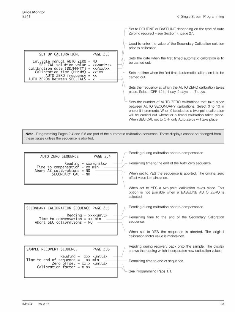
Set to ROUTINE or BASELINE depending on the type of AutoZeroing required – see Section 7, page 27.
Used to enter the value of the Secondary Calibration solutionprior to calibration.
Sets the date when the first timed automatic calibration is tobe carried out.
Sets the time when the first timed automatic calibration is to becarried out.
Sets the frequency at which the AUTO ZERO calibration takesplace. Select: OFF, 12 h, 1 day, 2 days,......7 days.
Sets the number of AUTO ZERO calibrations that take placebetween AUTO SECONDARY calibrations. Select 0 to 10 inone unit increments. When 0 is selected a two-point calibrationwill be carried out whenever a timed calibration takes place.When SEC CAL set to OFF only Auto Zeros will take place.
Note. Programming Pages 2.4 and 2.5 are part of the automatic calibration sequence. These displays cannot be changed fromthese pages unless the sequence is aborted.
Reading during calibration prior to compensation.
Remaining time to the end of the Auto Zero sequence.
When set to YES the sequence is aborted. The original zerooffset value is maintained.
When set to YES a two-point calibration takes place. Thisoption is not available when a BASELINE AUTO ZERO isselected.
Reading during calibration prior to compensation.
Remaining time to the end of the Secondary Calibrationsequence.
When set to YES the sequence is aborted. The originalcalibration factor value is maintained.
Reading during recovery back onto the sample. The displayshows the reading which incorporates new calibration values.
Remaining time to end of sequence.
See Programming Page 1.1.
������������ �">! "�#�������� ������
���"(���������(&�3� ��=�!����#������������ ��'+3&��+(�/�3&������6&(��'7���3�.1���+(�$�������������������������������3�.1���+(������������������������������ ��=�!��,1�?&�(8*������ ��=�!�'�.��2��(������ ������
��=�!����A�#���������� �����C
������������������!��$�()������6&(��'7����������+�8+�0�('���+(��������(���� .+1�� =�8�3�.1���+('���#�����������������#� !��� ����#�
����#� !��� �">! "�#���A�#���� �����;
�������������������!��$�()������6&(��7�����������+�8+�0�('���+(��������(���� .+1������8�3�.1���+('���#�
� �����!���@�!����A�#���������� �����B
����������������!��$�()��������6&(��'7�����+��($�+,�'�?&�(8�����������(������������=�1+�+,,'����������6&(��'7�������3�.1���+(�,�8�+1�������

Silica Monitor8241 6 Single Stream Programming
24 IM/8241 Issue 16
6.4 Page 3 – Set Up Instrument
6.5 Page 4 – Set Up Current Outputs
Enter the value of the previously entered security code.
Shows the current software issue level.
Set the required control temperature within the range 35 to45°C in 0.1°C increments. This temperature should be set to37°C or 5°C above the maximum ambient temperatureexpected.
Set the required display units for silica concentration (ppb, µg/lor µg/kg).
Enter setup security code (up to four digits) if required.
Set the current (real) date.
Set the current (real) time.
�����"#�!��#��������������� �����9
�����(��1�'�8&1��*�8+$��������
�����"#�!��#��������������� �����4������������+,�2�1���''&�������������+(�1+3����0�1��&1���������5���������������'03�*�&(��'����6&(��'7 3��1�'��&0�'�8&1��*�8+$���������
����������������������������� ������
���������������������� � �������������������������� � �����
!#"#��� $%&'��()��(*�+,��-���.+/������0�1�����1'�2�33��3��1��-��(��� &�+���3�.1���+(������
Set the current output to any range between the followingmaximum and minimum limits of SiO2, 0 to 2000µg/l rangeinstrument – 0 to 20 and 0 to 2000µg/l, or 0 to 50 and 0 to5000µg/l.
If set to YES the Current Outputs are held during calibration.
Set to one of the following ranges: 0 to 10, 0 to 20 or 4 to20mA.
If required, the instrument can automatically transmit apercentage of the full scale test signal: 0, 25, 50, 75, 100% ofthe current output selected.
������!!�#�������������� ���C�9
���&�0&��1�()��4���9��+������6&(��'7��3�.1���+(�-+3$���#����&�0&��1�()������9��+������6&(��'7��3�.1���+(�-+3$���#�������&�0&���*0��������+����� ������'��+&�0&����#�

Silica Monitor8241 6 Single Stream Programming
IM/8241 Issue 16 25
6.6 Page 5 – Alarm Relay Setup
6.7 Page 6 – Factory Settings
Select YES or NO as required.
Set the required setpoint values within the instrument range.
Select the alarm action required – HIGH or LOW.
If fail-safe action is required select YES.
Relay actuation and alarm LED indication can be delayed inthe event of the alarm condition. If the alarm condition clearswithin the programmed delay time, the alarm function is notactivated and the delay time is reset. Set the required delaytime in the range 0 to 99 minutes in 1 minute increments.
A differential set point can be set as a percentage of the setpoint value. The differential setting operates on the set point.Example – a 5% differential setting operates 2.5% above andbelow the setpoint.
���� � !��!�� ���������������� ���;�9
��� 4��(�.3�$���#��� 4�'��0+�(��������6&(��'7���� 4��8��+(����� ��� ���(�.3�$���#��� ��'��0+�(��������6&(��'7���� ���8��+(�����
�����#�!�� ����#:"�! "�#������ ���;�4
���� 3�1��,��3'�,�������������� 3�1��$�3�*��������(�� 3�1��-*'��1�'�'������E
Set the differential required between 0 and 5% in 1%increments.
Enter the value of the previously entered security code.
Used for diagnostic purposes only.
Displays the output of the photocell pre-amplifiers. Used onlyfor information and photocell balance adjustment.
Enter a security code (up to four digits) if required.
����: ��!����"#������������� � ���B�9
���(��1�,�8�+1*�'����()'�����������'�8&1��*�8+$� ����
�����: ��!����"#������������� ���B�4
� !#"#����-�'��0�1�����1'��1��,�8�+1*�'����($�'-+&3$�(+��(+1��33*�1�?&�1���$%&'���(���-�*�8�(�+(3*�.��'���&0��,��-��(�8�''�1*��?&�0��(���'��/��3�.3������#���!������ "�����#��"#��������! "�#�� # ��
��������!"� ��� �">! "�#������ ���B��
�����������������!��$�()������6&(��'7������0��3�)(��(��@�1��$����������@+3�'������0��3�)(��(��@�1�,�����������@+3�'� 3��1�,�8�+1*�'����()'�������������8&1��*�8+$��������

Silica Monitor8241 6 Single Stream Programming
26 IM/8241 Issue 16
Used for the calibration of the A and D converter. This is set upduring the manufacture of the processor board and must notbe changed unless full details of the procedure are known.
Connect a 100Ω resistance to the input of the respectivetemperature input.
Connect a 150Ω resistance to the input of the respectivetemperature input.Wait for the display to stabilize before moving on to the nextstep. The new calibration datum is automatically entered.
Calibration is performed on the 4 to 20mA range, but valuesare valid for 0 to 10 and 0 to 20mA ranges.Connect a digital current meter to the respective outputterminals and use the raise and lower buttons to adjust therespective output up or down to within <±0.25% of themaximum current output.
For service purposes only. Must normally be set to ON. Whenset to OFF, the signal processing to remove the effects ofchemical noise and air bubbles is bypassed.
Set to 2000µg/l or 5000µg/l to suit the cuvette fitted, i.e.50mm path cuvette = 2000µg/l and 10 mm path cuvette =5000µg/l.
Cuvette filling time normally set to 40s (0 to 5000µg/l system)or 55s (0 to 2000µg/l system) to ensure that the cuvetteoverflows before the lamp is switched on.
35min These do not require further adjustment except20min for Recover On Sample Time which can be20 min increased if the sample value is near zero.
Enables the acceptable range of zero offset to be selectedbefore a calibration fail alarm is initiated. 50 to 500, OFF,normally set to 100.
Enables the acceptable range of calibration factor to beselected before a calibration fail alarm is initiated. 0.15 to 0.5,OFF, normally set to 0.2.
��������!"� ��� �">! "�#������ ���B��
����!��$�"���F�1+�G�@������������!��$�"���'0�(�H�@�������������!�,�"���F�1+�G�@�������������!�,�"���'0�(�H�@��������
��������!"� ��� �">! "�#������ ���B�C
��0�1��&1��8-�(4�F�1+�499������������0�1��&1��8-�(4�'0�(�4;9������������0�1��&1��8-�(��F�1+�499������������0�1��&1��8-�(��'0�(�4;9����������
��������!"� ��� �">! "�#������ ���B�;
����������&11�(��+&�0&��4�C� ����������&11�(��+&�0&��4��9� ����������&11�(��+&�0&����C� ����������&11�(��+&�0&�����9�
������"#�!��#�"�"#���������� ���B�B�����'&1�$�/�1��.3��,�3��1����#�����������&��+&�0&��1�()����9�G�����
�������&/�����,�33�()������������'������������ ��=�!���������������(����#� !��� �">! "�#��������������(���!�8+/�1*�+(�'��03���������������(
���� �">! "�#� � !����������� ���B�I
��=�1+�+,,'���1�()� � 9�9 H�G ����6&(��'7����3�,�8�+1�1�()� � 4�9 H�G ����

Silica Monitor8241 7 Calibration
IM/8241 Issue 16 27
7 CalibrationCalibration of the monitor is carried out by replacing the samplesolution sequentially with two solutions of known silicaconcentration – see Section 4.1, page 10. Initially a zero silicasolution, which is generated internally by the monitor then, ifrequired, a secondary solution is passed through the monitor –see Section 8.1.2, page 29. This calibration sequence can beinitiated automatically at preset times, or manually on demand.Since most of any drift which takes place affects the zero morethan the sensitivity, the monitor can be set up to carry outregular AUTO ZERO calibrations and less frequent AUTOSECONDARY calibrations. This reduces the instrument 'downtime' to an absolute minimum. Manual one or two pointcalibration sequences can also be initiated. Calibrationprogramming is covered in Section 6 (single stream) andAppendix A (multi-stream).
On initiation, either manual or automatic, the 'Cal' LED isilluminated and the remote Calibration Mode relay is energized.Two solenoid valves, SV2 and SV3, are energized sequentiallyto generate the zero solution and then (if selected) to admit thesecondary standard solution. At each stage of the sequence,sufficient time is allowed to displace the previous solution andallow the reading to stabilize.
The calibration sequence is shown in Table 7.1.
After calibration, the outputs from the optical systemcorresponding to the two solutions, are used to calculate newzero and calibration factor values, thus compensating for anydrift or sensitivity in the reagents or liquid handling performancecharacteristics.
The new zero and calibration factor can be displayed inOperating Page 1 (a calibration factor of 1.00 is the nominalvalue). This parameter is intended to indicate the performance ofthe monitor and in particular the chemical solutions. If the valueis outside factory pre-set limits, a calibration fail alarm is initiatedand the 'Out of Service' LED is lit.
The calibration factor can be defaulted to 1.00 (seeProgramming Page 2.2) following maintenance. The displayedreading can be brought onto scale with the and switches to allow the reading to be observed to assess thestability of the monitor prior to carrying out a calibration.
Initially, a BASELINE AUTO ZERO calibration is manuallyinitiated to establish the new base line zero when a new reagentsolution is installed. This sets the zero offset value, displayed onProgramming Page 1, to 00.0. Following a BASELINE AUTOZERO a SECONDARY calibration is initiated. Subsequent timedROUTINE AUTO ZEROs generate a new zero offset value whichcan then be assessed to check for zero drift within the life of thereagents (normally five weeks). If the zero offset is outsidefactory pre-set limits, a calibration fail alarm is initiated and the'Out of Service' LED is lit.
Activity AUTO ZEROIntroduce SECONDARY CALIBRATION Solution
(if selected)Introduce Sample Normal Operation
Valve Energized SV3 SV2 None None
Timing (Default) 35 minutes 20 minutes 20 minutes
Table 7.1 Calibration Sequence

Silica Monitor8241 8 Maintenance
28 IM/8241 Issue 16
8 Maintenance8.1 Chemical SolutionsThe reagent and standard solutions listed below are necessaryto maintain the monitor in operation. It is recommended that thesolutions should be freshly made and stored in polyethylenecontainers. Polyethylene apparatus should also be used toprepare the solutions where possible.
If solutions are purchased from a proprietary chemical supplier,care should be exercised in storing the containers. They shouldbe date stamped, used in strict rotation and not used after theirexpiry date.
8.1.1 Reagent SolutionsThe following four reagent solutions are necessary to maintainthe monitor in operation for a period of five weeks. Thecontainers and associated tubing are color coded for ease ofidentification.
� 1st Acid – 0.3M sulfuric acid (RED channel)
Place approximately 4 litres high purity water in a plasticbeaker and carefully add 160 (±0.5)ml analytical reagentgrade concentrated sulfuric acid, H2SO4, (1.84 s.g.).Transfer the solution to a 10 litre plastic container andmake up to 10 litres with more high purity water.
� Ammonium molybdate solution (VIOLET channel)
Dissolve 150 (±1)g analytical reagent grade ammoniummolybdate, (NH4)6Mo7024.4H2O, in approximately 6 litreshigh purity water. Transfer the solution to a 10 litre plasticcontainer, add 30 (±5)ml ammonia solution, NH4OH,(0.880 s.g.) and make up to 10 litres with more high puritywater.
� 2nd Acid – 1.0M sulfuric acid (ORANGE channel)
Place approximately 7.5 litres high purity water in apolyethylene beaker. Surround the beaker with runningcold water and add slowly and carefully 545 (±1)ml ofanalytical reagent grade concentrated sulfuric acid,H2SO4, (1.84 s.g.). Stir the solution continuously duringthe addition. Add 200 (±10)g analytical reagent gradecitric acid crystals, C6H8O7.H2O and stir to dissolve. Allowthe solution to cool to room temperature and then transferto a 10 litre plastic container. Make up to 10 litres withmore high purity water.
� Reduction solution – ascorbic acid (BROWN channel)
Dissolve 132 (±1)g analytical reagent grade ascorbic acid,C6H8O6, in approximately 6 litres of high purity water. Addto this solution 0.60 (±0.01)g analytical reagent gradedisodium – EDTA, C10H14O8N2Na2.2H2O. When dissolved,add 13 (±1)ml analytical reagent grade formic acid,H(COOH) and transfer to a 10 litre plastic container. Diluteto 10 litres with more high purity water.
The '1st Acid' and '2nd Acid' reagents have a shelf life of severalmonths; the molybdate and reduction solutions should beprepared for immediate use. The latter, when stored at roomtemperature, loses up to approximately 5% of its activity in onemonth.
Caution. Great care must be taken to avoid contaminationof these solutions with silica which is present all around us.Reagent and standard solution containers must be emptiedand then rinsed with high purity water, not simply toppedup. Tops on containers must always be fitted to keep outdust which can contain large concentrations of silica. Theperformance of the monitor relies heavily on the integrity ofthese solutions, so it is very important that they areprepared, stored and handled with great care.
Warning.
� Concentrated sulfuric acid must be handled with greatcare at all times; in particular, ensure that whendiluting concentrated acid, it is added to the water,not water to the acid. Wear appropriate protectiveclothing, i.e. rubber gloves and full face protection.
� Concentrated ammonia solution is extremely volatileand toxic; it must always be handled under a fumehood. Wear appropriate protective clothing, i.e.rubber gloves and full face protection.
Note. The citric acid quantity must be increased to120g l–1 in this reagent if phosphate is present in thesample water.

Silica Monitor8241 8 Maintenance
IM/8241 Issue 16 29
8.1.2 Standard Solutions
A stock solution of 1000mg l–1 silica, SiO2, can be obtained inone of the following three ways:
1. the preferred method
Purchase a 1000mg l–1 SiO2 stock solution* from aproprietary chemical supplier.
or
2. from sodium fluorosilicate
a. Dissolve 3.133 (±0.001)g of sodium fluorosilicate(Na2SiF6 – the purest grade available) inapproximately 900ml of high purity water. Ensurethat all solid has dissolved fully by stirring thesolution for several hours.
b. Transfer the solution to a one litre volumetric flaskand make up to the mark with more high puritywater.
c. Store the solution in a polyethylene bottle.
or
3. from sodium metasilicate
a. Dissolve 3.530 (±0.001)g of sodium metasilicatepenta hydrate (Na2SiO3.5H2O – the purest gradeavailable) in approximately 900ml of high puritywater. Ensure that all solid has dissolved fully bystirring the solution for several hours.
b. Transfer the solution to a one litre volumetric flaskand make up to the mark with more high puritywater.
c. Store the solution in a polyethylene bottle.
* If a stock solution of 1000mg l–1 silicon (Si) is available, this canbe diluted to obtain a 1000mg l–1 SiO2 solution by taking46.81ml and diluting to 100ml with high purity water in avolumetric flask. The dilution factor is 2.139 times.
Dilute the appropriate stock solution with high purity water toobtain the secondary calibration solution. The dilution should becarried out using polyethylene apparatus wherever possible.
8.1.3 Rinse Solution for Internal PipeworkIt is important that the internal pipework of the monitor iscleaned every five weeks as part of the routine maintenance.This prevents the gradual fouling of molybdate precipitation inthe pipework which can introduce errors. Problems such asnoise can also be caused by contaminated pipework.
One litre of the rinse solution is prepared as follows:
1. Dissolve 100g of sodium hydroxide pellets, NaOH, inapproximately 600ml of high purity water in a plasticcontainer. Allow the solution to cool to ambienttemperature.
2. Add to the solution 5g di-sodium EDTA and stir todissolve.
3. Transfer the above solution to a 1 litre measuring cylinderand make to the mark with more high purity water. Mixwell and store in a tightly stoppered plastic container.Stored in this container the solution is stable for manymonths.
Note. Ideally the high purity water used for diluting thestandard solution should contain less than 1µg l–1 SiO2. If,however, this is not possible to obtain and the silicaconcentration is known, it is recommended that allowanceis made for the background level in the high purity waterwhen calculating the actual silica concentration of thestandard.
Note. The accuracy of the monitor over its total range isgoverned by the choice of the secondary standard solutionvalue. A monitor calibrated at 20µg l–1, for example, wouldnot exhibit the best accuracy at 2000µg l–1.
In the case of a multi-stream, the concentration of thesolution should be chosen to coincide with the point ofgreatest required accuracy. However, a value thatcorresponds to 80% of the current output range would bemore appropriate for a single stream monitor.
Note.
� Store all standard solutions in tightly stopperedpolyethylene bottles.
� The stock solutions remain stable for approximatelyone year, but standard solutions with concentrationsof less than 1mg l–1 should be prepared only forimmediate use.
Warning. Sodium hydroxide is extremely caustic and mustbe handled with great care. Wear gloves and eyeprotection.

Silica Monitor8241 8 Maintenance
30 IM/8241 Issue 16
8.2 Scheduled ServicingThe following servicing schedule has been produced as ageneral guide only. Because the monitor is designed for a widerange of applications, where the nature of the sample can varyconsiderably, it may be necessary to amend the schedule to suitthe particular installation and sample conditions.
8.2.1 Regular Visual ChecksIt is recommended that the monitor and the sampling systemshould be visually inspected on a regular basis to ensure thecorrect functioning of the system and to check the integrity ofthe readings.
1. Check for leaks particularly around the sample and drainpipework connections.
2. Confirm sample flow by checking delivery to the constanthead unit and effluent from the drain.
3. Check liquid levels in the reagent and standard solutioncontainers.
4. Inspect all tubing and liquid handling components forleaks and deterioration.
5. Check for malfunction indications on the instrumentdisplay.
8.2.2 Five-weekly1. Carry out the normal visual checks detailed in Section
8.2.1.
2. Discard old reagent and standard solutions, cleancontainers thoroughly and refill with fresh solutions, seeSection 8.1, page 28.
3. Replace the pinch tube between the cuvette and the drainmanifold. Release the tube from the pinch valve bypressing the centre plunger and remove. Replace withnew silicon rubber tube from the spares kit. Ensure thatthe tube is fully inserted into the valve to avoid any leakageof solution from the cuvette.
4. Set the following parameters to YES using ProgrammingPage 2.1:
Five-Weekly System FlushFive-Weekly Solution ReplacementDefault Calibration Parameters
5. Rinse internal pipework – see Section 8.2.4, page 30. It isimportant that this procedure is carried out to ensure thatthe monitor tubing is kept in a good clean condition,essential for correct monitor operation.
6. If having not already done so energize the secondary CALvalve (see Programming Page 2.3) and leave for 15minutes. Adjust the reading on scale with the and
switches and run the monitor for one to two hours topurge the old solution and assess stability.
7. If the monitor exhibits good stability, i.e. ±2% of reading,carry out a two-point BASELINE calibration – seeProgramming Page 2.3.
8. Check the condition of the sample filters and replace themif necessary. Ensure that new filters are fitted correctly bytaking note of the flow directions indicated on the filterbodies.
8.2.3 Twelve-monthly1. Service pump – see Section 8.2.6, page 31.
2. Replace all internal plumbing tubing – see Section 8.2.7,page 31.
3. Set 'Annual Service' to YES – see Programming Page 2.1.
4. Carry out the normal five-weekly schedule not alreadycovered in steps 1) and 2).
8.2.4 Rinsing Internal Pipework
Carry out the following procedure on a five-weekly basis:
1. Remove the secondary standard tube from the solutioncontainer and immerse in the rinse solution.
2. Energize the secondary cal. valve (see Section 6, page 19,Programming Page 2.2) and allow the rinse solution to runthrough the monitor for about 30 minutes.
3. Remove the secondary solution tube from the rinsesolution, wash it well with high purity water and return it tothe secondary calibration solution.
4. Carry out a calibration of the monitor as described inSection 8.2.2, starting at step 6).
Warning. It is vital that good maintenance in this respect isadhered to and that all leaks of potentially aggressivechemical solutions are attended to as soon as possible andspillages are cleaned up.
Caution. All unused solutions must be discarded; thecontainers must be rinsed with high purity water beforerefilling with the fresh solution.
Note. Before proceeding to the next step, multi-streamusers must select single stream mode as described inSection 4.3.
Note.
� It cannot be stressed strongly enough that thefive-weekly chemical clean with the rinse solution isvitally important. It is also very effective at reducingcalibration problems, drift and signal noise. Anyevidence of white or blue precipitate in the mixer orreaction coil must be removed with the rinse solution.
� If the routine cleaning procedure has not been carriedout on a regular basis as scheduled, or the liquidhandling section is in poor condition, run the rinsesolution through the monitor for several hours.

Silica Monitor8241 8 Maintenance
IM/8241 Issue 16 31
8.2.5 Consumable Spares Kit – see Section 10If one is not supplied, it should be ordered before the end of thefirst year of operation. This kit includes all the componentswhich are recommended for annual replacement (refer to thedetails in the spares kit). This annual refurbishment ensures ahigh level of reliability from the monitor for many years. The kitshould be re-ordered when used so that all the items areavailable throughout the following years operation.
The kit contains:
� one set of pump tubing,
� one set of pump capstans,
� a syringe for checking free flow though valved and tubingand for clearing blockages,
� a complete set of plumbing tubing and
� sundry items – 'O' rings, tube connectors, pump tubebungs and sample filters.
8.2.6 Peristaltic Pump – Fig. 8.1It is recommended that the pump tubing and pump capstans,supplied in the Consumable Spares Kit, are replaced after oneyear of operation. Carry out the procedure given in Fig. 8.1.
8.2.7 Replacement of Plumbing Tubing – Fig. 8.2All the following items are included in the Consumable SparesKit.
1. Remove each section of the sample and reagent plumbingtubing in turn and replace with new tubing of the samelength.
2. Remove drain tubing and replace with new tubing of thesame length.
3. It is recommended that the sample and drain tubing toand from the monitor is inspected and replaced if thecondition of the tubing is poor or shows evidence of anybuild-up of solids.
8.3 Shutdown ProcedureThe monitor can be left with the pump switch off for up to 24hours without any detrimental effects. However, for longerperiods it must be shutdown correctly to prevent chemicalprecipitation in the pipework resulting in extensive maintenanceand recommissioning.
Perform the following Shutdown sequence:
1. Close the sample valve up-stream of the monitor.
2. Rinse the internal pipework – see Section 8.2.4, page 30.It is important to flush the reagent bottle tubes; so theseneed to be immersed in the rinse solution also.
3. Repeat the process with high purity water to flush out therinse solution.
4. Switch off the monitor.
5. Remove the pressure plates from the peristaltic pumpsand release the tube from the pinch valve.
6. Empty reagent and standard containers and rinse withhigh purity water.
Caution. It is essential that the correct tube, which waschosen with great care, is fitted in each position. Failure todo this could upset the performance of the monitor or resultin solution leakages around connections due to chemicalattack.

Silica Monitor8241 8 Maintenance
32 IM/8241 Issue 16
Fig. 8.1 Maintaining the Peristaltic Pump
Note.
� The bungs are designed to grip the pump tube when compressed by the platen. Two sizes of tube are used so it isessential that the correct size of bung is fitted.
� It is immaterial which tube passes over which pump roller, but for neatness the front tube should be de-gassed sample, thecentre tube reagent and the rear tube, raw sample.
�('��!��� (" � ��!���$��!��� (" !(2�'�(�!���!�����!���"������'"�$��!�'����!����$������!�����'�)��(%�!�����!���!$�!����$%�L$�!��� $'�!�$�!$��$�,�!��� ��!��)
�"$���!��� (" � ��!���2+�&�%"�+'0��L��.��!��.���'!�!����� '!��'�(�!��!�����!���"������'"�!(%�'�&%���+�!$����%!����� $'�!�$�)��(���!�����!���&$%-�%#!$�%����'��!��� ��!��)
��'�$����!������ (" �!(2��&%$"��!'�%�' ��!���!(2���$����!$%��!�!���%��%�$&�!�����'�M� (���!��!(2��$(!�$&�!���.%$""�!'���#�#�'��%#)
�"$���!���%�!�����.�'�%�-�$��!��� (" �'��&!��#�%�"$�������$&�!����� '!��')
��!�!�����-��� '!���&%$"�!���,�!�$��!����1�.$����'��&!�'$�!���%$���%'��%��$&&'�!&%$"�$�����$!��%)��6&�!�%�!�����.�'�%�-)
��''�!�����-� (" �!(2�'�&%$"�!��,�!�!�%$(.��!���!(2��2(�.'���#��'��.%$""�!')��$����!�!$�!��� %$ %��!��!(2���$����!$%��!�!��%��%�$&�!�����'�)
��!�!�����-� (" �!(2��2(�.'��#�'��"'�&%$"�!���,�!�!$�!�����&!���#�'�#��$&�!��� (" )
�$��!��!���!(2�'����!%���+�$��!�� (" �%$���%')
�
�
�
/
�
;
:
<

Silica Monitor8241 8 Maintenance
IM/8241 Issue 16 33
Fig. 8.2 Replacement of Plumbing Tubing
Note.
� Replace the tube between the drain manifold assembly and the contaminated drain tundish (see Fig. 1.1) with the tubeprovided – part no. 8241 146.
� Tube specifications for the multi-stream version are as those in the table, but repeated for each stream.
����% B���$-
�%��.�5%$-� �$��! �#
�%��.�
�$��!
�#5%$-�
5�(�
5�(� 5�(�
5�(�
5�(�
8�����;�
8�����;�
8����88:
8����88:
8����88:
8����8�8
8����8�8
8����8�8
8����8�8
8�����:�
8�����8;
8�������
8�������
8�������
8�������
8�����:�
8������;
8�����;�
8�����;�
8�����;�
*�+N��6 ����� � ���$����!$%N��� ���$����!$%
5�(�Part No. Tube Specification
0212 007 2 mm ID Santoprene
0212 020 0.51 mm ID Santoprene
0212 362 2.4 mm ID Tygon
0212 173 1.5 mm ID pvc
0212 206 1 mm ID silicon rubber
0212 222 3.2 mm ID silicon rubber
0212 156 9.5 mm ID pvc

Silica Monitor8241 8 Maintenance
34 IM/8241 Issue 16
8.4 Unscheduled Servicing
8.4.1 Monitor Diagnostic InformationThe monitor is fitted with extensive diagnostics which provideinformation on routine servicing and problems that havedeveloped. Any one of these problems illuminate the 'Out ofService' LED and de-energize the normally energized 'Out ofService' alarm relay. Timed calibration is inhibited but could bestarted manually. This alarm also goes into an alarm state whenthe monitor is switched off. The information is displayed whenan alarm has been raised to indicate the cause of the problem.The diagnostics are displayed in Table 8.1.
8.4.2 Malfunction of the MonitorA calibration fail for any reason could be caused by almost anypart of the liquid handling section of the monitor including thesolutions.
Mechanical components which are involved with the liquidhandling, e.g.: pumps; valves; tubing and tubing connections,should be systematically checked for correct operation and forleaks or blockages which change the chemical conditions withinthe monitor.
In the majority of cases any problems experienced are generallyfound to be associated with the chemistry and the liquidhandling section.
Noise maybe due to air bubbles sticking in the pipework and tothe walls on the cuvette. Degassing of the sample is normal dueto pre-heating of the sample on entry into the liquid handlingsection. However, the monitor is designed so this does notnormally affect its performance. If the problem is excessive asystem chemical rinse should be carried out to clean and re-wetthe liquid handling system and cuvette – see Section 8.2.4,page 30. Reducing the control temperature also helps – seeSection 6, page 19, Programming Page 3.1.
The most common problems are associated with the reagent orstandard solutions. Any unpredictable problems may be due tothe standard or reagent solutions, or their flow through themonitor. If any doubts exist regarding the integrity of thesesolutions, they should be replaced with freshly preparedsolutions in the early stages of the fault finding investigations.
If the monitor fails to produce results as expected, the mostlikely cause is the standards, either contaminated when handledor (and most likely) made up with poor quality water, possiblycontaining high levels of silica. Incorrectly prepared reagentsmay give a poor calibration factor. Silica, or SiO2, forms 28% ofthe earths crust, so is to be found all around us in dust or dirt inbottles etc. If the solutions are purchased from a proprietarychemical supplier, care should be taken in storing thecontainers; they should be date stamped, used in strict rotationand not used after their expiry date. When measuring tracelevels, contamination can only be avoided by preparing andhandling solutions with great care. Laboratory glassware is notto be used for low concentration solutions; use plastic instead.
Caution. Check that there have been no unauthorizedmodifications, e.g. incorrect tubing fitted.
Display Explanation Action
Flashing Parameter out of range –
Next 5 weekly service /Overdue
Five-weekly service overdue Carry out a five-weekly service and acknowledge (set to YES) in Programming Page 2.1 (see Section 6.3, page 22, or Appendix A for multi-stream version).
Next yearly service /Overdue
Yearly service overdue Carry out a yearly service and acknowledge (set to YES) in Programming Page 2.1 (see Section 6.3, page 22, or Appendix A for multi-stream version).
Monitor in service Monitor operating correctly None.
Control temperature stabilizing
The mains power supply has been re-instated and the temperature of the two heaters is stabilizing
Allow i) sufficient time for the heaters to stabilize at their operating temperature, and ii) a further 10 minutes for a full reaction to take place.
Out of reagent Reagent solution bottle(s) are empty Replace reagent solution bottles.
Pumps off Pump switch is in the OFF position Switch pump(s) on – see Fig. 1.1.
Control temperature high One or more of the heaters is greater than ±2°C of the control temperature setpoint
Normally this indicates a fault in the heater control unit but, in the case of a high alarm, a high ambient temperature could be the cause – see Section 6.4, page 24, Programming Page 3.1 (or Appendix A for multi-stream version).Control temperature low
In test mode see page 2.2
Test mode parameter(s) in Programming Page 2.2 are active (set to YES)
Refer to page indicated; check and correct the setting(s).
Excessive zero offset Large zero drift has occurred since the last BASELINE calibration
Refer to Section 8.5.1
Calibration factor too high
Indicates higher than normal silica sensitivity
Refer to Section 8.5.2
Calibration factor too low Indicates lower than normal silica sensitivity
Refer to Section 8.5.2
Table 8.1 Diagnostic Messages

Silica Monitor8241 8 Maintenance
IM/8241 Issue 16 35
8.4.3 Effects of Loss of Power to the MonitorThe action taken by the monitor following an unforeseen loss of power is dependant on the length of time the power was off. Table8.2 shows the alternative actions performed by the monitor.
8.5 Simple Checks
8.5.1 Unstable or Erratic Readings
1. Check the flow of sample into the cuvette.
2. Check the flow of each reagent through the pump.
3. Check that the pinch tube is fitted correctly into the pinchvalve.
4. Ensure that the drain/fill cycle is taking place normally.Illumination can be seen via the plastic prism on the top ofthe lamp housing – see Fig. 8.3.
5. Ensure that the cuvette overflows through the bottom lefthand outlet tube before the lamp lights during eachdrain/fill cycle.
6. Rinse the pipework for 30 minutes with cleaning solution(see Section 8.2.4, page 30) to remove any build-up ofmolybdate precipitate.
7. Carry out a monitor response test – see Section 8.5.3,page 36.
Status of the MonitorPeriod of Loss of Power
Less than 5 minutes Greater than 5 minutes
In Between CalibrationsNormal operation resumed after temperature stabilization*.
A ZERO calibration is automatically performed one hour after temperature stabilization*.
During CalibrationsAfter temperature stabilization*, the current calibration is re-started.
The current calibration is re-started one hour after temperature stabilization*.
* This period allows sufficient time for the heaters to stabilize at their operating temperature, plus a further 10 minutes for a full reaction to take place.
Table 8.2 Effects of Loss of Power to The Monitor
Note. All references to 'Programming Pages' are found inSection 6 for single stream versions of the monitor. Beforecarrying out tests on the multistream version, it is essentialthat only one stream is selected – see Section 4.3, page 13– to emulate single-stream operation.
Note. It cannot be stressed strongly enough that thefive-weekly chemical rinse with the rinse solution is vitallyimportant. It is also very effective at reducing calibrationproblems, drift and signal noise. Any evidence of white orblue precipitate in the mixer or reaction coil must beremoved with the rinse solution.
Fig. 8.3 Simple Electronic Response Test
��" �$(�!��.���!�
���'(%��.���$!$�����$('��.
���'(%��.�(��!!�
��" �$('��.
�&�%�������$!$�����$('��. ���'!��
�%�'"
�������%#
#�$�&����2����� �-�%��*���� �� ��(������ ��&������
'�$�&����2����� �-�%��*���� �� ��/����� ���3���������*���� �
�������%#

Silica Monitor8241 8 Maintenance
36 IM/8241 Issue 16
8.5.2 Low/High Calibration Factor Value1. Check and, if necessary, replace the standard solution.
2. Check and, if necessary, replace the reagent solutions.
3. Switch 'Energize AUTO ZERO valve' to YES onProgramming Page 2.2.
4. Disconnect the tube on the AUTO ZERO valve furthestaway from the reaction block. Ensure that solutionemerges from the valve nipple.
5. Switch 'Energize AUTO ZERO valve' to NO and set'Energize SECONDARY CAL valve' to YES.
6. Lift the secondary calibration solution tube out of thecontainer for a few seconds and ensure that air is beingdrawn into the tube.
7. Carry out a monitor response test – see Section 8.5.3,page 36.
8.5.3 Monitor Stability/Response Test1. Check that the temperature on both heaters is under
control and stable.
2. Switch 'Default calibration parameters' to YES onProgramming Page 2.1.
3. Switch 'Energize AUTO ZERO valve' to YES onProgramming Page 2.2.
4. Run the monitor for 30 minutes.
5. Use the and switches to generate a sensiblereading of the sample on the display on ProgrammingPage 0. Note the reading over a 30 minute period toensure a stable reading.
6. Switch 'Energize AUTO ZERO valve' to NO and 'EnergizeSECONDARY CAL valve' to YES.
7. Run the monitor for 30 minutes. Note that the reading onProgramming Page 0 has changed by approximately thevalue of the secondary solution and is stable over a 30minute period.
8. If successful, set the monitor to normal operation, i.e.de-energize the SECONDARY CAL valve and carry out abaseline calibration – see Programming Page 2.3.
8.5.4 Simple Electronic Response Test1. Remove the optical system cover.
2. Switch 'Default calibration parameters' to YES onProgramming Page 2.1.
3. Set 'Switch lamp on continuous' to YES on ProgrammingPage 2.2. This stops the drain/fill sequence.
4. Place a thin card between the lamp housing and themeasuring cuvette (see Fig. 8.3A) to stop the lightreaching the measuring photocell.
5. Wait six seconds and note that the reading on the displayon Programming Page 0 goes off the scale.
6. Remove the card and place it between the lamp housingand the reference photocell housing to stop the lightreaching the measuring photocell (Fig. 8.3B).
7. Wait six seconds and note that the reading goes to zero.Note also that the intensity of the light, seen through theplastic prism on top of the lamp housing, increases.
8. Remove the card and set the monitor to normal mode viaProgramming Pages 2.1 and 2.2.
8.6 Setting Up the Optical SystemThis lamp is pre-set at the factory and normally needs no furtheradjustment. Also, the lamp is run well below its rated voltageand should have a long life. However, in the unlikely event ofexciter lamp or cuvette board failure, the optical system willrequire resetting. Section 8.6.2 explains how to adjust the lampalignment to ensure that the maximum amount of light is hittingthe photoelectric cell. Section 8.6.3 explains how to set a newcuvette board, i.e. balance the two outputs from the photocells.If only the cuvette board is being replaced, then the lampalignment requires no adjustment. However, both steps need tobe carried out if the lamp position has been disturbed.
8.6.1 Replacing the Exciter Lamp – Fig. 8.41. Remove (pull off) the optical system cover (Fig. 4.6).
2. Switch off the instrument, unscrew the threespring-loaded positioning screws (Fig. 8.4) and lift off thelamp mounting plate.
3. Pull out the old lamp and fit a new one.
4. Temporarily switch on the instrument and check that thelamp illuminates during each drain/fill cycle.
5. If the lamp is working, switch off the instrument andsecure the lamp mounting plate. Ensure that the springsare in place. Switch on the instrument.
Now align the lamp – see Section 8.6.2, page 37.
Caution. Clean up any spillages from the second mixerchamber.
Note. It cannot be stressed strongly enough that thefive-weekly chemical clean with the rinse solution is vitallyimportant. It is also very effective at reducing calibrationproblems, drift and signal noise. Any evidence of white orblue precipitate in the mixer or reaction coil must beremoved with the rinse solution.
Caution. Do not touch the glass envelope of the new lamp;use a tissue to hold it.

Silica Monitor8241 8 Maintenance
IM/8241 Issue 16 37
8.6.2 Aligning the Exciter Lamp1. To avoid spillages in the next step depress the pinch valve
plunger for two to three seconds to drain the cuvette.
2. Remove all tubing from the cuvette connectors.
3. Unscrew fully the two screws holding the cuvette in placeand remove the cuvette.
4. Scroll to Programming Page 2.2 and use the switchto select 'YES' for 'Switch lamp on continuous'.
5. Loosen off the three screws on the lamp mounting plateuntil the light beam falls directly onto the photoelectric cellwindow. Placing a piece of white card aids this adjustment– see Fig. 8.4B.
6. Fit the cuvette and the associated tubing.
Now set up the cuvette board – see Section 8.6.3, page 37.
8.6.3 Setting Up the Cuvette Board1. Switch off the pumps.
2. To avoid spillages in the next step depress the pinch valveplunger for two to three seconds to drain the cuvette.
3. Remove the optical system cover if not already done so.Remove the cuvette inlet tube from the cuvette connector.This is a small diameter tube sited behind the drain tube.
4. Using a length of inlet tube from the spares kit connect asyringe filled with demineralized water to the cuvette inletconnector.
5. Slowly push the demineralized water through the cuvetteallowing it to overflow and occasionally depressing thepinch valve plunger.
Repeat this step once more before proceeding.
6. Refill the syringe and fill the cuvette until it just overflows.
7. Now scroll to the Programming Page 6.2. (The securitycode to enter Programming Page 6 is normally set to 41.)
The voltages at both the Read and Referencephotoelectric cells are displayed. The Reference voltageremains constant at approximately 2 V whereas the Readvoltage will vary depending on the intensity of the colorcomplex formed with the silica in the sample. Asdemineralized water is present in the cuvette, no colorexists and therefore represents a zero silica solution.
8. When the voltages are stable make fine adjustments withthe potentiometer, which is sited towards the bottom ofthe cuvette board (see Fig. 8.5) until the Read voltage isbetween 20 to 50mV less than the reference voltage.
9. Connect the cuvette tube to the cuvette inlet connectorand fit the optical system cover.
10. Switch the lamp out of 'Switch lamp on continuous' onProgramming Page 2.2 and switch on the pumps.
11. Allow the instrument to settle down for one hour beforeperforming a baseline calibration.
12. Allow the instrument to settle down for one hour beforeperforming a baseline calibration.
Fig. 8.4 Lamp Adjustment
��" �$(�!��.���!�
���'(%��.��$!$�����$('��.
���'(%��.�(��!!�
��" �$('��.
�&�%�������$!$�����$('��.
�%�������������
� %��.6�$�#�#�$'�!�$���.���%�-'
#O('!�'�%�-'!$����.��$ !����
�1�'
�-$��(��!!����(%��.���%�-'
��%#
#�$�-������ ����#�4���� ��������
'�$������ ������-�%����������� �� ���5
Fig. 8.5 Location of the Potentiometer on the Cuvette Board
�$-�%��( �+����!�3���4
$�!�.�� #O('!"��!��$!��!�$"�!�%

Silica Monitor8241 9 Specification
38 IM/8241 Issue 16
9 SpecificationInstallation Information
Install the monitor where the following conditions can be maintained:
Sample flow5 to 750ml min–1
Suspended solids< 10mg l–1, < 60 microns
Sample connectionsInlet 6mm, flexible hose connection
Outlet 9mm, flexible hose connection
Ambient temperature5 to 40ºC (41 to 104ºF)
Sample temperature5 to 55ºC (41 to 131ºF)
Reagent solutionsConsumption of each reagent is 10 liters per five weeks
Calibration solutionsA solution of one liter is required of concentration and formulationsuitable for the particular range and application
Enclosure dimensionsHeight 740mm (29 in.)
Width 540mm (21 in.)
Depth 240mm (9.5 in.)
Weight25kg (55lb)
Power supply110 to 120V or 220 to 240V, 50/60Hz, 100VA
Power supply tolerance+6% to –20%
Isolation voltageInput, output and power supply 1.5kV
Relay Contacts – Single Pole ChangeoverRating 250V AC 250V DC maximum
3A AC 3A DC maximum
Loading (non-inductive) 750VA 30W maximum(inductive) 750VA 3W maximum
Degree of protectionElectronics section IP65
Liquid handling Case IP31
Critical internal components IP65

Silica Monitor8241 9 Specification
IM/8241 Issue 16 39
General SpecificationRange
0 to 2000 g l–1 SiO2 or 0 to 5000 g l–1 SiO2
Maximum current output scale expansion0 to 20 g l–1 or 0 to 50 g l–1
Accuracy< ±2 g l–1 or < ±2% whichever is the greater
Reproducibility< ±2 g l–1 or < ±2% whichever is greater
Response time90% step change in approximately 16 minutes(dead time approximately 8 minutes)
Chemical driftDependent on reagents – typically less than 5% of reading/month
Control temperature range35 to 45ºC (95 to 113ºF)
Temperature Resolution 0.1ºC
DisplaysConcentration and programming data by backlit LCD graphicsdisplay module
Status indicationSingle stream
Two LEDs illuminated when concentration alarms are exceeded
Single LED illuminated when calibration in progress
Single LED illuminated when monitor is 'Out of Service'
Single LED illuminated when HOLD switch operated
Multi-streamSix LEDs illuminated when concentration alarms are exceeded
Six LEDs (one per stream) when stream 'Out of sample'
Single LED illuminated when calibration in progress
Single LED illuminated when monitor is 'Out of Service'
Single LED illuminated when HOLD switch operated
Current outputsSingle stream
Two isolated current outputs 0 to 10, 0 to 20 or 4 to 20mA softwareselectable over the full range of the monitor as standard. Rangeindependently selectable over the full range of the monitor
Maximum voltage load 15V
Multi-streamOne isolated current output per stream 0 to 10, 0 to 20 or 4 to 20mA,software selectable as standard. Range independently selectableover the full range of the monitor
Maximum voltage load 15V
Computer interfaceOptional second current output or RS485 serial interface
AlarmsSingle stream
Two concentration relay outputs.Can be configured as high or low concentration
Remote 'Out of Sample' alarm
Remote calibration-mode indication
Remote monitor 'Out of Service' alarm
Multi-streamMaximum of six (one per stream) relay outputs. Can be configured ashigh or low concentration, or ‘Out of Sample' alarms
Remote calibration-mode indication
Remote monitor 'Out of Service' alarm
Concentration alarm adjustmentProgrammable over monitor range
CalibrationFrequency and time of day programmable, fully automatic, plusmanual initiation on demand
EMCConforms to EMC Directive (89/336/EEC)
Classifications BS EN 500 81-2
BS EN 500 82-2
Electrical safety BS EM 61010-1
SS/8241 Issue 10

Silica Monitor8241 10 Spares List
40 IM/8241 Issue 16
10 Spares ListConsumable Spares
Refurbishment Spares
Strategic Spares
Part No. Description Qty.
8241 020 Consumable spares kit comprising pump tubes, pump capstans, plumbing tubing, tube connectors, 'O' rings, sample filters etc.
1
Part No. Description Qty.
0217 321 Magnetic Stirrer Bar – for mixer block 2
8241 135 Reagent container (red) – 1st acid 1
8241 138 Reagent container (purple) – molybdate 1
8241 137 Reagent container (orange) – 2nd acid 1
8241 136 Reagent container (orange) – 2nd acid(complete with float switch assy.)
1
8241 139 Reagent container (brown) – reduction 1
8240 085 Standard Solution Container – secondary 1
0234 019 Solenoid Valve – calibration/emergency 3
8240 054 Drain Pinch Valve 1
0217 220 Solution Container Sealing Cap 5
Part No. Description Qty.
8240 100 Constant Head Unit – single stream 1
8240 112 Constant Head Unit Module Assembly – multi-stream, one for each stream and complete with solenoid valve
1
0211 132 'O' Ring Seal between each constant head module
1
0234 023 Solenoid Valve – multi-stream 1
8240 114 Float Switch assy.–þ'Out of Sample' 1
8241 134 Float Switch assy.– 'Out of Reagent' 1
8240 090 Sample De-gasser 1
8241 150 Dynamic Mixer Block Assembly 1
8241 154 Static Mixer Block Assembly 1
8241 126 Reaction Block assy. 1
8240 110 Cuvette Assembly (0 to 2000 µg l–1) 1
8240 150 Cuvette Assembly (0 to 5000 µg l–1) 1
8240 117 Optical System Cover 1
8240 106 Drain Manifold Assembly 1
8240 107 Final Drain Assembly 1
8241 158 Photocell Housing Assembly – measuring 1
8241 159 Photocell Housing Assembly – reference 1
0231 462 Tungsten-Halogen Exciter Lamp 1
8241 156 Stirrer Motor Assembly –þterminated 1
8240 103 Pump Motor Assembly 50 Hz –þterminated 2
8240 123 Pump Motor Assembly 60 Hz –þterminated 2
8035 870 Pump Motor Coupling Assembly 2
8240 105 Heater Mat Assembly – optical system 1
8240 104 Cartridge Heater Assembly – reaction block 1
8240 196 Temperature Sensor Assembly – optical system 1
8240 142 Temperature Sensor Assembly – reaction block 1
0234 712 Heater Thermal Cut-out 2
8240 045 Electrical Connector Kit – Liquid handling section. Contains one set of male and female connectors for pump motor, heater, float witches and lamp
1
8240 046 Electrical Connector Kit – Float switch/solenoid valve. Contains one set of male and female connectors for the 'Out-of-Sample' float switches and a pair of connectors for the stream switching solenoid valve.
1
0234 726 Toggle Switch – mains, pump and hold 3
0234 714 Toggle Switch Boot 3
8240 235 Mother Board 1
8240 257 Power Supply Assembly (inc. transformer) 1
8240 205 Cuvette Board 1
8240 215 Microprocessor Board (without EPROM) 1
8240 296 Drive Board – single stream (50Hz) 1
8240 297 Drive Board – multi-stream (50Hz) 1
8240 298 Drive Board – single stream (60Hz) 1
8240 299 Drive Board – multi-stream (60Hz) 1
8240 265 Output Board – multi-stream 1
8240 266 Output Board – single stream 1
8240 267 Output Board – multi-stream + serial 1
8240 268 Output Board – single stream + serial 1
8240 245 Display Board – multi-stream 1
8240 246 Display Board – single stream 1
8240 120 Keypad/Bezel Assembly –þsingle stream 1
8240 121 Keypad/Bezel Assembly –þmulti-stream 1
8240 195 Ribbon cable 1
0216 041 Case Key 1
0216 042 Chemical Panel Door Catch 1
Part No. Description Qty.

Silica Monitor8241 10 Spares List
IM/8241 Issue 16 41
Fuse
EPROMs
Part No. Description Qty.
0231 548 F1 – 2A 20 x 5mm Anti-surge 250V AC 1
Part No. Description Qty.
8241 180 EPROM – single stream (English) 1
8241 181 EPROM – single stream (German) 1
8241 182 EPROM – single stream (French) 1
8241 183 EPROM – single stream (Spanish) 1
8241 190 EPROM – multi-stream (English) 1
8241 191 EPROM – multi-stream (German) 1
8241 192 EPROM – multi-stream (French) 1
8241 193 EPROM – multi-stream (Spanish) 1
8241 185 EPROM – single stream MODBUS serial (English)
1
8241 186 EPROM – single stream MODBUS serial (German)
1
8241 187 EPROM – single stream MODBUS serial (French)
1
8241 188 EPROM – single stream MODBUS serial (Spanish)
1
8241 195 EPROM – multi-stream MODBUS serial (English) 1
8241 196 EPROM – multi-stream MODBUS serial (German)
1
8241 197 EPROM – multi-stream MODBUS serial (French) 1
8241 198 EPROM – multi-stream MODBUS serial (Spanish)
1
8241 200 EPROM – single stream MODBUS/PROFIBUS serial (English)
1
8241 201 EPROM – single stream MODBUS/PROFIBUS serial (German)
1
8241 202 EPROM – single stream MODBUS/PROFIBUS serial (French)
1
8241 203 EPROM – single stream MODBUS/PROFIBUS serial (Spanish)
1
Part No. Description Qty.
8241 210 EPROM – multi-stream MODBUS/PROFIBUS serial (English)
1
8241 211 EPROM – multi-stream MODBUS/PROFIBUS serial (German)
1
8241 212 EPROM – multi-stream MODBUS/PROFIBUS serial (French)
1
8241 213 EPROM – multi-stream MODBUS/PROFIBUS serial (Spanish)
1
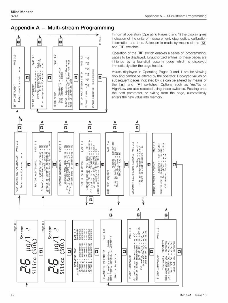
Silica Monitor8241 Appendix A – Multi-stream Programming
42 IM/8241 Issue 16
Appendix A – Multi-stream ProgrammingIn normal operation (Operating Pages 0 and 1) the display givesindication of the units of measurement, diagnostics, calibrationinformation and time. Selection is made by means of the and switches.
Operation of the switch enables a series of 'programming'pages to be displayed. Unauthorized entries to these pages areinhibited by a four-digit security code which is displayedimmediately after the page header.
Values displayed in Operating Pages 0 and 1 are for viewingonly and cannot be altered by the operator. Displayed values onsubsequent pages indicated by x's can be altered by means ofthe and switches. Options such as Yes/No orHigh/Low are also selected using these switches. Passing ontothe next parameter, or exiting from the page, automaticallyenters the new value into memory.
�����"#�!��#��������������� �����4
������������+,�2�1���''&������
�������+(�1+3����0�1��&1���������5�
��������������'03�*�&(��'����6&(��'7
3��1�'��&0�'�8&1��*�8+$���������
�����"#�!��#��������������� �����9
�����(��1�'�8&1��*�8+$��������
���������"�!� ������������ ������
��1�����(�&'�����4�����������C���;���B
�����������������#���#���#���#���#���#
��1����'�?&�(8���������������
�$� �.��/
������������������������������ ������
�����������������������������
�������������������������
!#"#��� $%&'��()��(*�+,��-���.+/�
�����0�1�����1'�2�33��3��1��-��(���
&�+���3�.1���+(������
�������"#:�!� "�#������������� ���4�4
�0��8�3�'*'�������0�1��&1��������5�
!��8��+(�.3+8<����0�1��&1��������5�
���������������=�1+�+,,'���������6&(��'7
����������3�.1���+(�,�8�+1�������
�������������������������������������
������������������������������������
�������"#:�!� "�#������������� ���4��
������������&(��'������������
#���� ��=�!��� ������������
��'�� ��=�!��� ������������
������#��������� ������������
��������'������� ������������
������������ �">! "�#�������� ������
���"(���������(&�3� ��=�!������#�
����������� ��'+3&��+(�/�3&������6&(��'7
���3�.1���+(�$�������������������������
������3�.1���+(���������������������
��������� ��=�!��,1�?&�(8*�����
��=�!�'�.��2��(������� ������
B��
� �����!���@�!����A�#���������� �����B
����������������!��$�()��������6&(��'7
�����+��($�+,�'�?&�(8�����������(
������������=�1+�+,,'����������6&(��'7
�������3�.1���+(�,�8�+1�������
����#� !��� �">! "�#���A�#���� �����;
��������������������!��$�()������6&(��7
������������+�8+�0�('���+(��������(
��������� .+1������8�3�.1���+('���#�
��=�!����A�#���������������� �����C
�������������������!��$�()������6&(��'7
�����������+�8+�0�('���+(��������(
����� .+1�� =�8�3�.1���+('���#�
�����������������#� !��� ����#�
�� "#�# #��� #��� �">! "�#���� �����9
�����(��1�'�8&1��*�8+$��������
�����!�"#��� "#�# #���������� �����4
������������;� ��<3*�0�0��1�('����#�
��;� ��<3*�'+3&��+(�1�03�8���(����#�
����������������� ((&�3�'�1/�8����#�
���,�&3��8�3�.1���+(�0�1�����1'���#�
3��1����(��(�(8��'�8&1��*��+$���������
������!�"#��� "#�# #��������� ������
��������(�1)�'�� ��=�!��/�3/����#�
����(�1)�'������#� !��� ��/�3/����#�
�(�1)�'�����!��#���� �����/�3/����#�
�������2��8-�3��0�+(�8+(��(&+&'���#�
��
B��
�������������! "#��� ��������� ���9��
�����'��0$���������������������������
��������1����4�������6&(��'7����������
��������1������������6&(��'7����������
��������1������������6&(��'7����������
��������1����C�������6&(��'7����������
��������1����;�������6&(��'7����������
��������1����B�������6&(��'7����������
��" �#��"��"#:�!� "�#�������� ���4�9
#����;�2��<3*�'�1/�8����������
#����*��13*�'�1/�8���������������
���+(��+1��(�'�1/�8�
�� � ��3�
8���
�����
D)�3��
1��� �
�� � ��3�
8���
�����
D)�3��
1��� ����
����
�
���
����

Silica Monitor8241 Appendix A – Multi-stream Programming
IM/8241 Issue 16 43
��������!"� ��� �">! "�#������ ���B��
����!��$�"���F�1+�G�@��������
����
!��$
�"��
�'0�
(�H�
@���
����
���
���!
�,�"
���F
�1+�
G�@�
����
���
����
�!�,
�"��
�'0�
(�H�
@���
����
�
��������!"� ��� �">! "�#������ ���B��
�����������������!��$�()������6&(��'7
������0��3�)(��(��@�1��$����������@+3�'
������0��3�)(��(��@�1�,�����������@+3�'
� 3��1�,�8�+1*�'����()'
����������'�8&1��*�8+$���������
��������!"� ��� �">! "�#������ ���B�C
��0�1��&1��8-�(4�F�1+�499
����������
��0�1��&1��8-�(4�'0�(�4;9
����������
��0�1��&1��8-�(��F�1+�499
����������
��0�1��&1��8-�(��'0�(�4;9
����������
������"#�!��#�"�"#���������� ���B�B
�����'&1�$�/�1��.3��,�3��1����#
�����������&��+&�0&��1�()����9�G�����
�������&/�����,�33�()������������'
������������ ��=�!���������������(
����#� !��� �">! "�#��������������(
���!�8+/�1*�+(�'��03���������������(
���� �">! "�#� � !���������� ���B�I
�=�1+�+,,'���1�()�����9�9�H�G����6&(��'7
���3�,�8�+1�1�()����
4�9�H�G����
�%$"
���.���
�$���
�.��8
���
��
�!!�
#��
�
�
�����
���
� ���
C�9
��1�
���
4����
�1�(
)��
��9
��+��
��6
&(��'
7��
1����
�����
�1�(
)��
��9
��+��
��6
&(��'
7��
1����
�����
�1�(
)��
��9
��+��
��6
&(��'
7��
1����
C����
�1�(
)��
��9
��+��
��6
&(��'
7��
1����
;����
�1�(
)��
��9
��+��
��6
&(��'
7��
1����
B����
�1�(
)��
��9
��+��
��6
&(��'
7
��
��
��!!
�#
��
�
�����
���
��� �
��C
�4
���
���
�����
��&
�0&�
��*
0����
���
�+���
��
�&�
�+,
�'��0
3��
�($�
8��
+1���
#�
���
,�&
3��+&
�0&
��8&
11�
(����
���
�E���
���
�����
��
'��+
&�0
&����
#�
���
0�
'8�3�
�'�
�03�
���
�����
���
��('
��+
2(�
'8�3�
�'�
�03�
���
�����
���
��('
����
� !
��!�
� ��
��
����
����
����
���
;�9
�� 3
�1��
�!�3
�*�8
+(,�
)&1�
��+(
���
3�1�
����
����
����
�� 3
�1��
,��3
'�,�
����
����
����
����
�� 3
�1��
-*'�
�1�'
�'��
���E
��
�� �
!��
��#�
�#!
"�
#���
����
���
;�4
���
4��(
�.3�
$���
#���
4�'
��0+
�(��
����
��6&
(��'
7��
�� 4
��8�
�+(�
����
��
� ��
�(�.
3�$�
��#�
�� �
�'��
0+�(
����
����
6&(�
�'7
����
���
8��+
(���
��
��������!"� ��� �">! "�#������ ���B�;
����������&11�(��+&�0&��4�G�CG�9�
����������&11�(��+&�0&����G�CG�9�
����������&11�(��+&�0&����G�CG�9�
����������&11�(��+&�0&��C�G�CG�9�
����������&11�(��+&�0&��;�G�CG�9�
����������&11�(��+&�0&��B�G�CG�9�
����
: �
�!��
��
"#��
����
����
����
���
B�9
���(
��1�
,�8�
+1*�
'���
�()'
����
����
���'
�8&1
��*�
8+$�
����
���
����
�: �
�!�
���
"#�
����
����
����
���
B�4
� !
#"#�
���
-�'�
�0�1
����
�1'�
�1��
,�8�
+1*
�'��
��($
�'-+
&3$�
(+��
(+1�
�33*
�1�?
&�1�
��$%
&'��
�(��
�-�
*�8�
(�+(
3*�.
��'�
��&0
��,
��-�
�(�8
�''�
1*��
?&�0
��(�
��'�
�/��
3�.3
����
��#�
��!
����
�� "
��
���
#��
"#�
���
����
! "
�#��
#
��
�$���.��;)�
����������"�!� ��"�"#������� ���B�J
����#&�.�1�+,�'�1���'�,����$����
.����
�%$.%�"
"��.���.�'��)�
��#��)���%��#�' ��+�#�$��/���#
;�����������%'�$�'�%�' ��!����+)
No
te.
�P
ress
ing
adv
ance
s to
the
nex
t m
ain
page
, e.g
. 2.2
to 3
.0P
ress
ing
ad
vanc
es
to
the
next
sub-
page
, e.g
. 5.0
to 5
.1.
�If
an i
ncor
rect
sec
urity
cod
e is
ent
ered
and
is
pr
esse
d,
acce
ss
to
the
sub-
page
s is
not
allo
wed
but
the
cur
rent
page
leve
l is
mai
ntai
ned.
Pre
ssin
g d
ispl
ays
Pag
e 0.
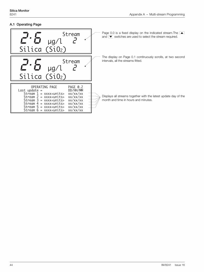
Silica Monitor8241 Appendix A – Multi-stream Programming
44 IM/8241 Issue 16
A.1 Operating Page
Page 0.0 is a fixed display on the indicated stream.The and switches are used to select the stream required.
The display on Page 0.1 continuously scrolls, at two secondintervals, all the streams fitted.
Displays all streams together with the latest update day of themonth and time in hours and minutes.
�������������! "#��� ��������� ���9�������'��&0$�����������������������������������1����4�������6&(��'7������������������1������������6&(��'7������������������1������������6&(��'7������������������1����C�������6&(��'7������������������1����;�������6&(��'7������������������1����B�������6&(��'7����������
��3�8���������
��1���D)�3
��3�8���������
��1���D)�3� ��

Silica Monitor8241 Appendix A – Multi-stream Programming
IM/8241 Issue 16 45
A.2 Page 1 – DiagnosticsIndicates the date when the next relevant routine maintenanceis required. When the date is exceeded, 'overdue' is displayed,and in the case of the 5-weekly service, the 'Out of Service'LED is illuminated.
This message indicates that the monitor is working normallybut it is replaced with the relevant information, whennecessary, by the monitor diagnostics – see Section 8.4.1.
The control temperature of the two heaters is displayed in °C.
Zero Offset indicates the zero drift since the last BASELINEAUTO ZERO CALIBRATION.
The Calibration Factor is calculated after a SECONDARYCALIBRATION; the nominal value is 1.00 but this differsbetween individual monitors and the reaction controltemperature. It is intended to indicate the condition of themonitor and the chemical solutions.
Current date and time.
The date when the next AUTO ZERO CALIBRATION is to becarried out. If the automatic calibration is disabled, then OFF isdisplayed in place of the date.
The date of the last ZERO calibration.
The date when the next SECONDARY CALIBRATION is to becarried out. If the secondary calibration is disabled, then OFF isdisplayed in place of the date.
The date of the last SECONDARY calibration.
��" �#��"��"#:�!� "�#��������� ���4�9
#����;�2��<3*�'�1/�8����������#����*��13*�'�1/�8���������������
���+(��+1��(�'�1/�8�
�������"#:�!� "�#������������� ���4�4
�0��8�3�'*'�������0�1��&1��������5�!��8��+(�.3+8<����0�1��&1��������5����������������=�1+�+,,'���������6&(��'7����������3�.1���+(�,�8�+1��������������������������������������������������������������������������������
�������"#:�!� "�#������������� ���4��
������������&(��'������������#���� ��=�!��� ��������������'�� ��=�!��� ������������������#��������� ��������������������'������� ������������
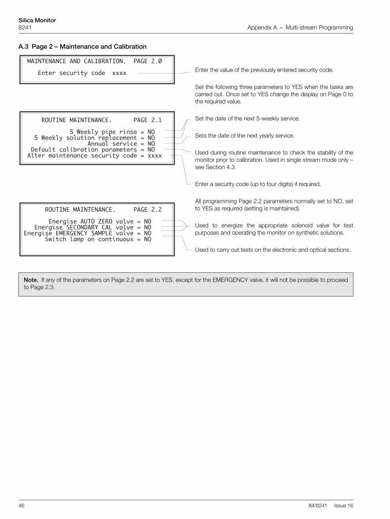
Silica Monitor8241 Appendix A – Multi-stream Programming
46 IM/8241 Issue 16
A.3 Page 2 – Maintenance and Calibration
Enter the value of the previously entered security code.
Set the following three parameters to YES when the tasks arecarried out. Once set to YES change the display on Page 0 tothe required value.
Set the date of the next 5-weekly service.
Sets the date of the next yearly service.
Used during routine maintenance to check the stability of themonitor prior to calibration. Used in single stream mode only –see Section 4.3.
Enter a security code (up to four digits) if required.
All programming Page 2.2 parameters normally set to NO, setto YES as required (setting is maintained).
Used to energize the appropriate solenoid valve for testpurposes and operating the monitor on synthetic solutions.
Used to carry out tests on the electronic and optical sections.
Note. If any of the parameters on Page 2.2 are set to YES, except for the EMERGENCY valve, it will not be possible to proceedto Page 2.3.
�� "#�# #��� #��� �">! "�#���� �����9
�����(��1�'�8&1��*�8+$�������
������!�"#��� "#�# #��������� ������
��������(�1)�'�� ��=�!��/�3/����#�����(�1)�'������#� !��� ��/�3/����#��(�1)�'�����!��#���� �����/�3/����#��������2��8-�3��0�+(�8+(��(&+&'���#�
�����!�"#��� "#�# #���������� �����4
�������������;� ��<3*�0�0��1�('����#����;� ��<3*�'+3&��+(�1�03�8���(����#������������������� ((&�3�'�1/�8����#�����,�&3��8�3�.1���+(�0�1�����1'���#�� 3��1����(��(�(8��'�8&1��*�8+$��������

Silica Monitor8241 Appendix A – Multi-stream Programming
IM/8241 Issue 16 47
Set to ROUTINE or BASELINE depending on the type of AutoZeroing required – see Section 7.
Used to enter the value of the Secondary Calibration prior tocalibration.
Sets the date when the first timed automatic calibration is tobe carried out.
Sets the time when the first timed automatic calibration is to becarried out.
Sets the frequency at which the AUTO ZERO calibration takesplace. Select: OFF, 12h, 1 day, 2 days,…7 days.
Sets the number of AUTO ZERO calibrations that take placebetween AUTO SECONDARY calibrations. Select 0 to 10 inone unit increments. When 0 is selected a two-point calibrationwill be carried out whenever a timed calibration takes place.When SEC CAL set to OFF only Auto Zeros will take place.
Note. Programming Pages 2.4 and 2.5 are part of the automatic calibration sequence. These displays cannot be changed fromthese pages unless the sequence is aborted.
Reading during calibration prior to compensation.
Remaining time to the end of the Auto Zero sequence.
When set to YES the sequence is aborted. The original zerooffset value is maintained.
When set to YES a two-point calibration takes place. Thisoption is not available when a BASELINE AUTO ZERO isselected.
Reading during calibration prior to compensation.
Remaining time to the end of the Secondary Calibrationsequence.
When set to YES the sequence is aborted. The originalcalibration factor value is maintained.
Reading during recovery back onto the sample. The displayshows the reading which incorporates new calibration values.
Remaining time to end of sequence.
See Programming Page 1.1.
������������ �">! "�#�������� ������
���"(���������(&�3� ��=�!����#������������ ��'+3&��+(�/�3&������6&(��'7���3�.1���+(�$�������������������������������3�.1���+(������������������������������ ��=�!��,1�?&�(8*������ ��=�!�'�.��2��(������ ������
�������� ��=�!����A�#�������� �����C
������������������!��$�()������6&(��'7����������+�8+�0�('���+(��������(���� .+1�� =�8�3�.1���+('���#�����������������#� !��� ����#�
����#� !��� �">! "�#���A�#���� �����;
�������������������!��$�()������6&(��7�����������+�8+�0�('���+(��������(���� .+1������8�3�.1���+('���#�
���� �����!���@�!����A�#������� �����B
����������������!��$�()��������6&(��'7�����+��($�+,�'�?&�(8�����������(������������=�1+�+,,'����������6&(��'7�������3�.1���+(�,�8�+1�������

Silica Monitor8241 Appendix A – Multi-stream Programming
48 IM/8241 Issue 16
A.4 Page 3 – Set Up Instrument
Enter the value of the previously entered security code.
Shows the current software issue level.
Set the required control temperature within the range 35 to45°C in 0.1°C increments. This temperature should be set to37°C or 5°C above the maximum ambient temperatureexpected.
Set the required display units for silica concentration (ppb, µg/lor µg/kg).
Enter setup security code (up to four digits) if required.
Set the current (real) date.
Set the current (real) time.
Enables streams to be selected/de-selected.
Used to set the stream sampling order.
�����"#�!��#��������������� �����9
�����(��1�'�8&1��*�8+$�������
�����"#�!��#��������������� �����4������������+,�2�1���''&�������������+(�1+3����0�1��&1����������5���������������'03�*�&(��'�����6&(��'7 3��1�'��&0�'�8&1��*�8+$���������
���������"�!� ������������ ������
��1�����(�&'�����4�����������C���;���B�����������������#���#���#���#���#���#
��1����'�?&�(8���������������
����������������������������� ������
���������������������� � �������������������������� � �����
!#"#��� $%&'��()��(*�+,��-���.+/������0�1�����1'�2�33��3��1��-��(��� &�+���3�.1���+(������

Silica Monitor8241 Appendix A – Multi-stream Programming
IM/8241 Issue 16 49
A.5 Page 4 – Set Up Output Currents
A.6 Page 5 – Alarm Relay Setup
Set the current output to any range between the followingmaximum and minimum limits of SiO2 – 0 to 20 and 0 to2000µg/l for 0 to 2000µg/l systems, or 0 to 50 and 0 to5000µg/l for 0 to 5000µg/l systems.
Set to one of the following ranges: 0 to 10, 0 to 20 or 4 to20mA.
If set to YES each current output will be driven to a defaultvalue to indicate an Out of Sample condition on theappropriate stream.
Set the Out of Sample default current between 0 and 105% ofthe current output. As the output will limit at 102% during asignal over-range, a setting of 105% would be unique to anOut of Sample condition.
If required, the instrument can automatically transmit apercentage of the full scale test signal: 0, 25, 50, 75, 100% ofthe current output selected.
These set the sample time (see Section 4.3), i.e. the time themonitor samples each stream. Different times can be entereddepending on whether the new stream is higher or lower thanthe previous stream. This is determined by the values enteredon Programming Page 4.0. These parameters are normally setto 12 and 15 minutes, but could be increased if required.
������!!�#������������� ���C�9
�����1����4�����1�()����9��+����6&(��'7�����1����������1�()����9��+����6&(��'7�����1����������1�()����9��+����6&(��'7�����1����C�����1�()����9��+����6&(��'7�����1����;�����1�()����9��+����6&(��'7�����1����B�����1�()����9��+����6&(��'7
������!!�#�������������� ���C�4
�������������&�0&���*0��������+����� �&��+,�'��03���($�8��+1���#����,�&3��+&�0&��8&11�(��������E�������������'��+&�0&����#����0�'8�3��'��03��������������('��+2(�'8�3��'��03��������������('
If fail-safe action is required select YES.
A differential set point can be set as a percentage of the setpoint value. The differential setting operates on the set point.Example – a 5% differential setting operates 2.5% above andbelow the setpoint.
Set the differential required between 0 and 5% in 1%increments.
Select YES or NO as required.
Set the required setpoint values within the instrument range.
Select the alarm action required – HIGH or LOW.
Note. Programming Pages 5.2 and 5.3 are displayed on 4 and 6 channel versions only.
���� � !��!�� ���������������� ���;�9
�� 3�1���1�3�*�8+(,�)&1���+(��� 3�1��������������� 3�1��,��3'�,������������������� 3�1��-*'��1�'�'�����E
���� � !��!�� ���������������� ���;�4
��� 4��(�.3�$���#��� 4�'��0+�(��������6&(��'7���� 4��8��+(����� ��� ���(�.3�$���#��� ��'��0+�(��������6&(��'7���� ���8��+(�����

Silica Monitor8241 Appendix A – Multi-stream Programming
50 IM/8241 Issue 16
Select YES or NO as required.
Set the required setpoint values within the instrument range.
Select the alarm action required – HIGH or LOW.
Select YES or NO as required.
Set the required setpoint values within the instrument range.
Select the alarm action required – HIGH or LOW.
���� � !����#��#! "�#������� ���;��
��� ���(�.3�$���#��� ��'��0+�(��������6&(��'7���� ���8��+(����� ��� C��(�.3�$���#��� C�'��0+�(��������6&(��'7���� C��8��+(�����
���� � !����#��#! "�#������� ���;��
��� ;��(�.3�$���#��� ;�'��0+�(��������6&(��'7���� ;��8��+(����� ��� B��(�.3�$���#��� B�'��0+�(��������6&(��'7���� B��8��+(�����

Silica Monitor8241 Appendix A – Multi-stream Programming
IM/8241 Issue 16 51
A.7 Page 6 – Factory Settings
Enter the value of the previously entered security code.
Used for diagnostic purposes only
Displays the output of the photocell pre-amplifiers. Used onlyfor information and photocell balance adjustment.
Enter a security code (up to four digits) if required.
Used for the calibration of the A and D converter. This is set upduring the manufacture of the processor board and must notbe changed unless full details of the procedure are known.
Connect a 100Ω resistance to the input of the respectivetemperature input.
Connect a 150Ω resistance to the input of the respectivetemperature input.
Wait for the display to stabilize before moving on to the nextstep. The new calibration datum is automatically entered.
Calibration is performed on the 4 to 20mA range, but valuesare valid for 0 to 10 and 0 to 20mA ranges.Connect a digital current meter to the respective outputterminals and use the raise and lower buttons to adjust therespective output up or down to within <±0.25% of themaximum current output.
����: ��!����"#�������������� ���B�9
���(��1�,�8�+1*�'����()'�����������'�8&1��*�8+$��������
�����: ��!����"#������������� ���B�4
� !#"#����-�'��0�1�����1'��1��,�8�+1*�'����($�'-+&3$�(+��(+1��33*�1�?&�1���$%&'���(���-�*�8�(�+(3*�.��'���&0��,��-��(�8�''�1*��?&�0��(���'��/��3�.3������#���!������ "�����#��"#��������! "�#�� # ��
��������!"� ��� �">! "�#������ ���B��
�����������������!��$�()������6&(��'7������0��3�)(��(��@�1��$���������@+3�'������0��3�)(��(��@�1�,����������@+3�'� 3��1�,�8�+1*�'����()'�����������'�8&1��*�8+$��������
��������!"� ��� �">! "�#������ ���B��
����!��$�"���F�1+�G�@������������!��$�"���'0�(�H�@�������������!�,�"���F�1+�G�@�������������!�,�"���'0�(�H�@��������
��������!"� ��� �">! "�#������ ���B�C
��0�1��&1��8-�(4�F�1+�499�����������0�1��&1��8-�(4�'0�(�4;9�����������0�1��&1��8-�(��F�1+�499�����������0�1��&1��8-�(��'0�(�4;9���������
��������!"� ��� �">! "�#������ ���B�;
����������&11�(��+&�0&��4�G�CG�9� ����������&11�(��+&�0&����G�CG�9� ����������&11�(��+&�0&����G�CG�9� ����������&11�(��+&�0&��C�G�CG�9� ����������&11�(��+&�0&��;�G�CG�9� ����������&11�(��+&�0&��B�G�CG�9�

Silica Monitor8241 Appendix A – Multi-stream Programming
52 IM/8241 Issue 16
For service purposes only. Must normally be set to ON. Whenset to OFF, the signal processing to remove the effects ofchemical noise and air bubbles is bypassed.
Set to 2000µgþl–1 or 5000µgþl–1 to suit the cuvette fitted, i.e. 50 mm path cuvette = 2000µgþl–1 and 10 mm path cuvette= 5000µgþl–1.
Cuvette filling time normally set to 40s (0 to 5000µgþl–1
system) or 55s (0 to 2000µgþl–1 system) to ensure that thecuvette overflows before the lamp is switched on.
35min. These do not require further adjustment except20min. for Recover On Sample Time which can be20min. increased if the sample value is near zero.
Enables the acceptable range of zero offset to be selectedbefore a calibration fail alarm is initiated. 50 to 500, OFF,normally set to 100.
Enables the acceptable range of calibration factor to beselected before a calibration fail alarm is initiated. 0.15 to 0.5,OFF, normally set to 0.2.
Number of streams fitted into the monitor.
������"#�!��#�"�"#���������� ���B�B���'&1�$�/�1��.3��,�3��1����#�����������&��+&�0&��1�()����9�G�����
�������&/�����,�33�()������������'������������ ��=�!���������������(����#� !��� �">! "�#��������������(���!�8+/�1*�+(�'��03���������������(
���� �">! "�#� � !���������� ���B�I
��=�1+�+,,'���1�()� � 9�9 H�G ����6&(��'7����3�,�8�+1�1�()� � 4�9 H�G ����
����������"�!� ��"�"#������� ���B�J
����#&�.�1�+,�'�1���'�,����$����

Silica Monitor8241 Appendix B – Wiring Schematic
IM/8241 Issue 16 53
Appendix B – Wiring Schematic
Fig. B.1 Wiring Schematic
����
��P����
���*
�
��9��
�
���7�
���9��
� ������
��� ����
�
9��
���
������P����
���88��
���88��
����/
���� �
���� �
����/
��
����
��
����
������ ��
��
�����
���
�I�
�
����/
���8
�3�/
4���� �
��9�� ����
����;
����;
�����
�����
����/
����/
�����
�����
�����
�����
�����
�����
��� ����
��� ����
��� ���/
��� ����
��� ���;
����7�
� ������
��� ����
����
��P����
�
9��
���
���88��
���88��
���8
�3�/
4
���8
�3�/
4
���*
��
����
��
����
������ ��
��
�����
���
�I�
�
��9�� ����
��� ����
��� ����
��� ���/
��� ����
��� ���;
� �%�$-�%
�%��.�
5�(�
9%���
B���$-
�$�#
�-�!��
�$��!
�#
���,
5%$-�
5�(�
9%���
�$��!
�#
���,
5%$-�
�(%0($�'�
B���$-
5�(�
5�(�
9%���7�#
�#75�(�
B���$-P��!�
�#75%$-�
9%���
5���,
P��!�
�%��.� 9%�+
�(%0($�'�
B���$-
5���,
P��!�
�%��.� 9%�+
�(%0($�'�
B���$-
�#
5�(�
B���$-
���,
�%��.�
�%��.�
5%$-� �#75%$-�
5���,
P��!�
���,
9%�+
�#79%���
B���$-75���,
B���$-79%���
9%�+75�(�
�#75�(�
�#75���,
P��!�7�#
5�(�
�#
P��!�75�(�
P��!�7�#
���������
���������
�D��
�D��
������P����
P ����B���
P ����B���
�$��!
9%���
�$��!7�# �%��.�7�#
P��!�75�(�
9%���7�#
B���$-75�(�
9%���7B���$-
��%!��$��!
�
@
�
��
�
��
�
��
�("
�-�!��
�
��
�#75�(�
��$���"
�
� �
P��!�75�(�
B���$-75�(�
�$� (!$�I�%$���������
�
��
�$!��'�#
9%���7�#
�#75�(�
5%$-� �
��,
�#
�$��!
9%���
5�(�
5���,
P��!�
�%��.�
9%�+
�(%0($�'�
B���$-
��$�!��
;
��$�!��
�
��$�!��
/
������/
�������
������;
�$��
����$!$����!%�������
�$����
��������$!$����!%�������
5�(�
������
P��!�
������
���88�3�
��!�%��
�!4
���88�3�
�%!%�#.�����!�%4
�
@
9%���
�#
5%��#
�$%�
5�(�
�#
�#
5�(�
��%���
�
��
��.��!�5$!!�����$�!��-�!��
9%���7�#
�#75�(�
5%$-�
�#
�$��!
9%���
5�(�
5���,
P��!��%��.�
9%�+
�(%0($�'�
B���$-
��$�!��
�
��$�!��
�
��$�!��
�
�������
�������
�������
���,
B���$-�������
5���,
���,
�#
9%���
5�(�
�#75���,
P��!�7�#
�%��.�
�#75%$-�
5%$-�
B���$-
�(%0($�'�
P��!�
9%�+
5�(�
B���$-�#
���$�#�%+��!�#��$������������
�"�%.���+���"
������������
P��!�7�#
�$��!�%%�%
�$!$%
P��!�75�(�
B���$-
� � �
�$��("
�$!$%��
P��!�7�#
P��!�75�(�
B���$-
� � �
�$����!�%��
3���!�%��
�!4
�$�����������
5���,�������
�$����!�%��
3��%!%�#.�����!�%4
5�(��������
9%���
�$��!
9%���7�#
B���$-7�#
��<<�
��
<<
�
�$!��'�#
� � �
P��!�7�#
P��!�75�(�
B���$-
9%���7�#
�$��("
�$!$%��
9%���
�$��!

Silica Monitor8241 Appendix C – Replacing Software Eprom
54 IM/8241 Issue 16
Appendix C – Replacing Software Eprom
1. Remove the screws from the electronics section frontpanel and swing it open to reveal the printed circuitboards (PCBs).
2. Remove the four screws that secure the two PCBrestrains to stand-off pillars and remove the restrains.
3. Disconnect the ribbon cable – see Fig. C1. Note that thecable feeds in from the front of the board.
4. Carefully ease the processor board (see Fig. C1) from themother board.
5. Remove the software EPROM chip, preferably using anextractor. This chip is the third from the top (the onlylabelled chip – see Fig. C1).
6. Fit the replacement chip ensuring correct orientation in itssocket.
7. Complete the procedure as follows:
– Plug the PCB onto the mother board;
– connect the ribbon cable to the processor board;
– fit the PCB restraints and secure them using thepreviously removed screws;
– close the electronics section front panel and secureit using the previously removed screws.
8. The monitor may now be put into service.
9. Check program parameters – see instruction manual.
10. Carry out a routine 2-point calibration.
Warning. Switch off the monitor and electrically isolate itbefore carrying out the following steps.
Caution. Employ normal antistatic precautions whilehandling chips and PCBs.
Fig. C.1 8240 Electronics Section
�$!��%2$�%#
�22$����2��!$����' ��+���#
*�+ �#
���%$ %$��''$%5$�%#�?���'��$(!�3'!� ������4
�� �(.��22$����2��3�!� ������4
�$&!-�%���������� )� �����?�'!� '������A� ;
/
�

Silica Monitor8241 Notes
IM/8241 Issue 16 55
Notes

Silica Monitor8241 Notes
56 IM/8241 Issue 16

PRODUCTS & CUSTOMER SUPPORT
Products
Automation Systems• for the following industries:
– Chemical & Pharmaceutical– Food & Beverage– Manufacturing– Metals and Minerals– Oil, Gas & Petrochemical– Pulp and Paper
Drives and Motors• AC and DC Drives, AC and DC Machines, AC Motors to
1kV• Drive Systems• Force Measurement• Servo Drives
Controllers & Recorders• Single and Multi-loop Controllers• Circular Chart and Strip Chart Recorders• Paperless Recorders• Process Indicators
Flexible Automation• Industrial Robots and Robot Systems
Flow Measurement• Electromagnetic Flowmeters• Mass Flowmeters• Turbine Flowmeters• Wedge Flow Elements
Marine Systems & Turbochargers• Electrical Systems• Marine Equipment• Offshore Retrofit and Refurbishment
Process Analytics• Process Gas Analysis• Systems Integration
Transmitters• Pressure• Temperature• Level• Interface Modules
Valves, Actuators and Positioners• Control Valves• Actuators• Positioners
Water, Gas & Industrial Analytics Instrumentation• pH, Conductivity and Dissolved Oxygen Transmitters and
Sensors• Ammonia, Nitrate, Phosphate, Silica, Sodium, Chloride,
Fluoride, Dissolved Oxygen and Hydrazine Analyzers• Zirconia Oxygen Analyzers, Katharometers, Hydrogen
Purity and Purge-gas Monitors, Thermal Conductivity
Customer Support
We provide a comprehensive after sales service via a WorldwideService Organization. Contact one of the following offices fordetails on your nearest Service and Repair Centre.
United KingdomABB LimitedTel: +44 (0)1453 826661Fax: +44 (0)1453 829671
United States of AmericaABB Inc.Tel: +1 215 674 6000Fax: +1 215 674 7183
Client WarrantyPrior to installation, the equipment referred to in this manual mustbe stored in a clean, dry environment, in accordance with theCompany's published specification.
Periodic checks must be made on the equipment's condition. Inthe event of a failure under warranty, the following documentationmust be provided as substantiation:
1. A listing evidencing process operation and alarm logs at time of failure.
2. Copies of all storage, installation, operating and maintenance records relating to the alleged faulty unit.

IM/8
241
Issu
e 16
ABB has Sales & Customer Support expertisein over 100 countries worldwide
www.abb.com
The Company’s policy is one of continuous product improvement and the right is reserved to modify the
information contained herein without notice.
Printed in UK (02.10)
© ABB 2010
ABB LimitedOldends Lane, StonehouseGloucestershireGL10 3TAUKTel: +44 (0)1453 826661Fax: +44 (0)1453 829671
ABB Inc.Analytical Instruments9716 S. Virginia St., Ste. EReno, Nevada 89521USATel: +1 775 850 4800Fax: +1 775 850 4808