IM 0291(110)0 UNION & LINCOLN COUNTIES NB LENGTH: … · NB Control of Access to Exit 38 On Ramp...
18
DESIGN DESIGNATION ADT(2007) ADT(2027) DHV D T DHV T ADT V Interstate 29 SBL DESIGN DESIGNATION ADT(2007) ADT(2027) DHV D T DHV T ADT V Interstate 29 NBL 5660 9330 1260 100% 12.1% 26.6% 75 MPH 5600 9255 1250 100% 12.1% 26.6% 75 MPH R 50 W T 96 N R 51 W S T 2 20 SP 29 3.0 23 24 25 26 35 36 32 29 20 ALSEN 8 17 20 29 32 5 8 17 20 29 32 5 8 17 20 29 0.5 5.0 7.0 299 ST 303 ST 305 ST 472 AVE 471 AVE 2 1 12 14 13 23 24 25 36 35 2 14 23 36 24 13 12 1 35 25 23 24 14 13 12 1 2 46 312 ST 311 ST 309 ST 308 ST 306 ST 304 ST 302 ST 301 ST 300 ST 298 ST 469 AVE 470 AVE 307 ST 310 ST 297 ST 296 ST 295 ST 294 ST END PROJECT END NORTHBOUND LANES MRM 50.31 + 0.000 NBL MILEAGE 50.193 END SOUTHBOUND LANE MRM 46.31+0.000 SBL MILEAGE 46.188 BERESFORD MRM 40.00+0.570 SBL MILEAGE 40.491 BEGIN SOUTHBOUND LANE BEGIN PROJECT BEGIN NORTHBOUND LANE MRM 31.28+0.000 NBL MILEAGE 31.193 29 48 25 26 313 ST L I N C O L N C O U N T Y IM 0291(110)0 UNION & LINCOLN COUNTIES FENCE REPLACEMENT NB LENGTH: 19.000 MILES SB LENGTH: 5.697 MILES PCN 01M2 Sheet 1 of 18
Transcript of IM 0291(110)0 UNION & LINCOLN COUNTIES NB LENGTH: … · NB Control of Access to Exit 38 On Ramp...

DESIGN DESIGNATION
ADT(2007)
ADT(2027)
DHV
D
T DHV
T ADT
V
Interstate 29 SBL
DESIGN DESIGNATION
ADT(2007)
ADT(2027)
DHV
D
T DHV
T ADT
V
Interstate 29 NBL
5660
9330
1260
100%
12.1%
26.6%
75 MPH
5600
9255
1250
100%
12.1%
26.6%
75 MPH
T 9
3 N
R 50 W
T 94 N
T 95 N
T 9
6 N
R 51 W
S T
2
20
SP
29
3.0
23 24
2526
35 36
32
29
20
ALSEN
C L A Y C O U N T Y
8
17
20
29
32
5
8
17
20
29
32
5
8
17
20
29
0.5
5.0
4.0
7.0
299 ST
303 ST
305 ST
472 A
VE
471 A
VE
2 1
12
14 13
23 24
25
3635
2
14
23
36
24
13
12
1
35
25
23 24
14 13
12
12
46
312 ST
311 ST
309 ST
308 ST
306 ST
304 ST
302 ST
301 ST
300 ST
298 ST
46
9
AV
E
47
0 A
VE
307 ST
310 ST
471AVE
297 ST
296 ST
295 ST
294 ST
END PROJECT
END NORTHBOUND LANES
MRM 50.31 + 0.000 NBL
MILEAGE 50.193
END SOUTHBOUND LANE
MRM 46.31+0.000 SBL
MILEAGE 46.188
BERESFORD
MRM 40.00+0.570 SBL
MILEAGE 40.491
BEGIN SOUTHBOUND LANE
BEGIN PROJECT
BEGIN NORTHBOUND LANE
MRM 31.28+0.000 NBL
MILEAGE 31.193
29
48
2526
313 ST
U N I O N C O U N T Y
L I N C O L N C O U N T YIM 0291(110)0
UNION & LINCOLN COUNTIES
FENCE REPLACEMENT
NB LENGTH: 19.000 MILES
SB LENGTH: 5.697 MILES
PCN 01M2
Sheet 1 of 18

INDEX OF SHEETS Sheet 1 Layout Map Sheet 2 Index of Sheets Sheet 3 Estimate of Quantities Sheets 4 & 5 Table of Fence Quantities Sheets 6 – 8 Plan Notes Sheet 9 Traffic Control Sheets 10 & 11 Details for Right-of-Way Fence Sheets 12 – 18 Standard Plates
IM 0291(110)0UNION & LINCOLN COUNTIES
Sheet 2 of 18

ESTIMATE OF QUANTITIES
IM 0291(110)0UNION & LINCOLN COUNTIES
Sheet 3 of 18

TABLE OF FENCE QUANTITIESWIDE
DEPRESSION GATESMODIFIED MODIFIED & BARB
TYPE 3 TYPE 3 TYPE 6 2 3 WOOD STREAM WIREINTERSTATE 29 REMOVE R/W R/W R/W POST POST FENCE CROSSINGS 24'
LANE MRM TO MRM FENCE FENCE FENCE FENCE PANEL PANEL POST N.A.B.I. N.A.B.I.(LOCATION) Ft Ft Ft Ft Each Each Each Each * Each * NOTES
NBControl of Access at
Exit 31 On Ramp 360 360 3 1 1 Reset Tubular GateNB Exit 31 On Ramp 1080 1080 2 1
NBExit 31 On Ramp to
32.0 2696 2696 2 1
NB 32.0 to 33.0 5228 5172 56 6 2 5 1Depression: MRM 32.27
NB 33.0 to 34.0 1012 1012 2 1 133.21 to 33.29 425 425 1 1 Gate: MRM 33.2633.29 to 34.00 3749 3749 3 1
NB 34.0 to 35.0 5232 5232 12 3 1 Gate: MRM 34.33NB 35.0 to 35.31 1468 1468 6 1 1 Gate: MRM 35.29
NB 35.31 to 36.0 3669 3613 56 7 1 5 1 1
Depression: MRM 35.83 Gate: MRM 35.32
NB 36.00 to 37.00 5218 5162 56 14 5 5 1 1
Depression: MRM 36.60 & 36.89 Gate: MRM 36.32
NB 37.00 to 37.32 1600 1600 5 1 1 Gate: MRM 37.30
NB 37.32 to 38.00 3616 3560 56 3 3 5 1 1
Gate: MRM 37.34 Depression: MRM 37.62
NB38.00 to Exit 38 Off
Ramp 790 790 1 1NB Exit 38.00 Off Ramp 800 800 1 1
NBControl of Access at
Exit 38 Off Ramp 590 590 1 1
NBControl of Access to
Exit 38 On Ramp 597 597 3 1 1 Reset Tubular GateNB Exit 38 On Ramp 1062 1062 4
NBExit 38 On Ramp to
39.00 2577 2577 4 1NB 39.00 to 39.31 1637 1637 2 2NB 39.31 to 39.42 610 610 4 2 1 Gate: MRM 39.30
39.42 to 40.00 3050 3050 2 2NB 40.00 to 41.00 5230 5230 5 2 1 Gate: MRM 40.30
NB 41.00 to 42.00 5215 5159 56 7 2 5 1Depression: MRM 41.31
NB42.00 to Exit 42 Off
Ramp 450 450 3NB Exit 42 Off Ramp 825 825 1 1
NBControl of Access at
Exit 42 Off Ramp 645 589 56 3 1 5 1Depression: MRM 42.17
NBControl of Access at
Exit 42 On Ramp 660 660 1 1NB Exit 42 On Ramp 1380 1380 2
NBExit 42 On Ramp to
43.00 2226 2226 1
NB 43.00 to 44.00 5220 5164 56 3 5 1Depression: MRM 43.30
NB 44.00 to 44.30 1500 1500 2 1 1 Gate: MRM 44.28 NB 44.30 to 45.00 3658 3658 7 2 1 Gate: MRM 44.31NB 45.00 to 45.95 5010 5010 5 4 1 Gate: MRM 45.30
NB 45.95 to 46.00 210 210 2 5 1Depression: MRM 45.96
SHEET TOTALS: 79295 78693 392 210 122 55 40N.A.B.I. - Not a bid item.
IM 0291(110)0UNION & LINCOLN COUNTIES
Sheet 4 of 18

TABLE OF FENCE QUANTITIES (CONTINUED)WIDE
DEPRESSION GATESMODIFIED MODIFIED & BARB
TYPE 3 TYPE 3 TYPE 6 2 3 WOOD STREAM WIREINTERSTATE 29 REMOVE R/W R/W R/W POST POST FENCE CROSSINGS 24'
LANE MRM TO MRM FENCE FENCE FENCE FENCE PANEL PANEL POST N.A.B.I. N.A.B.I.(LOCATION) Ft Ft Ft Ft Each Each Each Each * Each * NOTES
NB 46.00 to 46.31 1515 1515 2 1 1 Gate: MRM 46.29
NB 46.31 to 47.00 3754 3698 56 5 3 5 1 1
Gate: MRM 46.32 Depression: MRM 46.63
NB47.00 to Exit 47 Off
Ramp 386 386 1NB Exit 47 Off Ramp 1005 1005 2 1
NBControl of Access to
Exit 47 Off Ramp 300 300 2
NBControl of Access to
Exit 47 On Ramp 300 300 3NB Exit 47 On Ramp 1850 1850 2 2
NBExit 47 On Ramp to
48.00 1754 1754 1NB 48.00 to 48.47 2461 2461 2 3 1 Gate: MRM 48.30NB 48.47 to 48.53 265 265 1 3NB 48.53 to 49.00 2466 2466 1 1
NB 49.00 to 50.00 5197 5071 126 3 5 10 2 1
Gate: MRM 49.30 Depression: MRM 49.63 & 49.75
NB50.00 to Exit 50 Off
Ramp 773 773 1 1NB Exit 50 Off Ramp 820 820 1 1
NBControl of Access to
Exit 50 Off Ramp 190 190 2
SB 40.57 to 40.95 1969 1969 5 1 Weigh StationSB 40.95 to 41.00 263 263 1
SB 41.00 to 42.00 5198 5142 56 5 1 5 1Depression: MRM 41.30
SB42.00 to Exit 42 On
Ramp 452 452 1SB Exit 42 On Ramp 800 800 1 1
SBControl of Access to
Exit 42 On Ramp 425 425 1 1
SBControl of Access to
Exit 42 Off Ramp 542 542 1 1 Reset Tubular GateSB Exit 42 Off Ramp 735 735 1 1
SBExit 42 Off Ramp to
43.00 2832 2832 1 1SB 43.00 to 44.00 5205 5205 3 1 Gate: MRM 43.30SB 44.00 to 44.30 1506 1506 2 1 1 Gate: MRM 44.28SB 44.30 to 45.00 3640 3640 7 4 1 Gate: MRM 44.32SB 45.00 to 45.30 1567 1567 1 2 1 Gate: MRM 45.29SB 45.30 to 45.58 1450 1450 1
SB 45.58 to 45.79 1099 1043 56 2 1 5 1Depression: MRM 45.68
SB 45.79 to 46.00 1120 1120 1 5 1Depression: MRM 45.99
SB 46.00 to 46.11 466 466 1SB 46.11 to 46.31 1045 1045 2 1 1 Gate: MRM 46.29
SHEET TOTALS: 53350 49755 294 3301 59 44 30 TOTALS: 132645 128448 686 3511 181 99 70
N.A.B.I. - Not a bid item.
IM 0291(110)0UNION & LINCOLN COUNTIES
Sheet 5 of 18

SPECIFICATIONS Standard Specifications for Roads and Bridges, 2004 Edition and Required Provisions, Supplemental Specifications and/or Special Provisions as included in the Proposal. COMPLETION DATE All work shall be completed on or before June 18, 2010. UTILITIES The Contractor shall contact the involved utility companies through South Dakota One Call (1-800-781-7474) prior to starting work. It shall be the responsibility of the Contractor to coordinate work with the utility owners to avoid damage to existing facilities. COORDINATION BETWEEN CONTRACTORS A separate contract for Project No. ES 0291(101)37 – PCN 4768 may be awarded to another Contractor for concrete pavement surfacing on Interstate 29 Northbound Lanes from MRM 37.0 to MRM 47.0. The Contractor shall schedule his work so as not to interfere with or hinder the progress of the work performed by other Contractors on the concrete paving project. HISTORICAL PRESERVATION OFFICE CLEARANCES To obtain State Historic Preservation Office (SHPO) clearance, a cultural resources survey may need to be conducted by a qualified archaeologist. The Contractor shall arrange and pay for this survey. In lieu of a cultural resources survey, the Contractor could request a literature search on the site and provide evidence that the site has been previously disturbed by farming, mining, or construction activities with a landowner statement that no artifacts have been found on the site. Jim Donohue, State Archaeological Research Center at 605-394-1937 shall be contacted for a literature search. If borrow material is furnished from within the current geographical reservation boundaries or historic boundaries of the Lake Traverse, Yankton, or Flandreau-Santee reservations, the Contractor shall obtain THPO (Tribal Historical Preservation Office) clearance from the Tribal Cultural Resources Officer. This requirement is in addition to the SHPO clearance. If no Tribal contact exists, the required SHPO clearance shall suffice, with documentation of Tribal contact efforts provided to SHPO. To facilitate SHPO and THPO responses, the Contractor should submit a cultural resources survey report or the results of the literature search along with a legal description of the site, a topographical map with the site clearly marked, and evidence of prior site disturbance to Terrence G. Keller, DOT Environmental Supervisor, 700 East Broadway Avenue, Pierre, SD 57501-2586 (605-773-3721). Allow 30 days from the date this information is submitted to the Environmental Engineer for SHPO approval. The Contractor is responsible for obtaining all required permits and clearances for the borrow and/or waste disposal site(s) prior to commencing construction activities at the borrow and/or waste disposal site(s). The Contractor shall provide the required permits and clearances to the Engineer at the preconstruction meeting. WASTE DISPOSAL SITE The Contractor will be required to furnish a site(s) for the disposal of construction/demolition debris generated by this project. Construction/demolition debris may not be disposed of within the State ROW. The waste disposal site(s) shall be managed and reclaimed in accordance with the following from the General Permit for Highway, Road, and Railway Construction/Demolition Debris Disposal Under the South Dakota Waste Management Program issued by the Department of Environment and Natural Resources. The waste disposal site(s) shall not be located in a wetland, within 200 feet of surface water, or in an area that adversely affects wildlife, recreation, aesthetic value of an area, or any threatened or endangered species, as approved by the Engineer. If the waste disposal site(s) is located such that it is within view of any ROW, the following additional requirements shall apply:
IM 0291(110)0UNION & LINCOLN COUNTIES
Sheet 6 of 18

WASTE DISPOSAL SITE (CONTINUED) 1. Construction/demolition debris consisting of concrete, asphalt concrete or other similar materials shall be
buried in a trench completely separate from wood debris. The final cover over the construction/demolition debris shall consist of a minimum of 1 foot of soil capable of supporting vegetation. Waste disposal sites provided outside of the State ROW shall be seeded in accordance with Natural Resources Conservation Service recommendations. Seeding recommendations may be obtained through the appropriate County NRCS Office. The Contractor shall control the access to waste disposal sites not within the State ROW through the use of fences, gates, and placement of a sign or signs at the entrance to the site stating No Dumping Allowed.
2. Concrete and asphalt concrete debris may be stockpiled within view of the ROW for a period of time not to
exceed the duration of the project. Prior to project completion, the waste shall be removed from view of the ROW or buried and the waste disposal site reclaimed as noted above.
The above requirements will not apply to waste disposal sites that are covered by an individual solid waste permit
s specified in SDCL 34A-6-58, SDCL 34A-6-1.13, and ARSD 74:27:10:06. a Failure to comply with the requirements stated above may result in civil penalties in accordance with South
akota Solid Waste Law, SDCL 34A-6-1.31. D Cost for furnishing waste disposal site(s), disposing of waste, maintaining control of access (fence, gates & signs)
nd reclamation of the waste disposal site(s) shall be incidental to the contract unit prices for the various items. a RESTORATION OF INSLOPES AND DITCHES Any slope area or ditch that is rutted or otherwise unduly disturbed during fencing operations shall be restored and seeded by the Contractor, at no expense to the State. Cost for this work shall be incidental to the contract nit prices for the various items. u
REMOVE FENCE The Contractor shall remove the existing right-of-way fence that is to be replaced as designated in the plans and/or as ordered by the Engineer. Limited Access Security - All fence removed during any one working day is to be replaced during the same day if livestock are being restrained. CLEARING Prior to installing right-of-way fence, the fence alignment shall be cleared of all trees, tree branches, tree stumps, brush, vegetation, debris, bladed and leveled to the satisfaction of the Engineer. Sod cleared from the fence alignment may be disposed on the interstate ditch back slope. Lumps or clods over 3 inches in diameter shall be
roken up. b Clearing will be paid for at the contract lump sum price. Payment shall be full compensation for labor and
quipment necessary to clear the entire line for fence and smooth ground irregularities. e FENCE ALIGNMENT Where fence is being removed and replaced, fence shall be installed on the same alignment as existing. It shall be the Contractor’s responsibility to preserve the fence alignment. TYPE 3 RIGHT-OF-WAY FENCE The Contractor shall furnish new posts. Install alternate wood and steel posts at 16'-6" spacing for Type 3 Right-f-Way Fence. o
MODIFIED TYPE 3 RIGHT-OF-WAY FENCE M
odified Type 3 Right-of-Way Fence shall be installed at wide depressions subject to flooding.
The Contractor shall furnish new 5” x 8’ wood posts. Install wood posts at 14' spacing for Modified Type 3 Right-of-Way Fence. Cost for 5” x 8’ wood posts shall be included in the contract unit price per each for Wood Fence Post.
IM 0291(110)0UNION & LINCOLN COUNTIES
Sheet 7 of 18

MODIFIED TYPE 6 RIGHT-OF-WAY FENCE The Contractor shall furnish new posts. Install alternate wood and steel posts at 14' spacing for Modified Type 6 Right-of-Way Fence. N
ote specification change for Modified Type 6 Woven Wire Fence to Design No. 832-6-11.
NEW POST PANELS Existing post panels shall be replaced. Existing 5 Post and 4 Post Panels shall be replaced with a combination of
Post and 3 Post Panels as determined by the Engineer. 2 The number of 2 Post and 3 Post Panels will be the actual number installed and will be paid for at the contract unit price per each. TUBULAR GATES Tubular Gates located within the project limits shall be removed, salvaged and reset on new post panels. Cost for removing, salvaging and resetting Tubular Gates shall be incidental to contract unit prices for the various tems. i GENERAL MAINTENANCE OF TRAFFIC Removing, relocating, covering, salvaging and resetting of permanent traffic control devices, including delineation, shall be the responsibility of the Contractor. Cost for this work shall be incidental to the contract unit prices for the various items unless otherwise specified in the plans. Any delineators and signs damaged or lost shall be eplaced by the Contractor at no cost to the State. r
Storage of vehicles and equipment shall be outside the clear zone and as near as possible to the right-of-way line. Contractor’s employees should mobilize at a location off the right-of-way and arrive at the work sites in a
inimum number of vehicles necessary to perform the work. m Indiscriminate driving and parking of vehicles within the right-of-way will not be permitted. Any damage to the vegetation, surfacing, embankment, delineators and existing signs resulting from such indiscriminate use shall be epaired and/or restored by the Contractor, at no expense to the State, and to the satisfaction of the Engineer. r
Contractors’ equipment and trucks will not be allowed to enter or exit lanes used by traffic or cross opposing traffic on Interstate 29. Median Maintenance Crossings shall not be used for construction activities. The Contractor shall submit a plan in writing detailing how haul vehicles will enter and exit the work site. The Contractor shall provide documentation that all breakaway sign supports comply with FHWA NCHRP 350 crash-worthy requirements. The Contractor shall provide installation details at the preconstruction meeting for all
reakaway sign support assemblies. b Cost for traffic control, including signs, shall be included in the contract lump sum price for Traffic Control, Miscellaneous.
IM 0291(110)0UNION & LINCOLN COUNTIES
Sheet 8 of 18

Published Date: 2nd Qtr. 2009
S
D
D
O
T
GUIDES FOR TRAFFIC CONTROL DEVICES
WORK BEYOND THE SHOULDER
PLATE NUMBER
Sheet 1 of 1
634. 01
W20
-1
ROAD
WORK
AHEAD
The signs illustrated are not required
if the work space is behind a barrier,
more than 2 feet behind the curb, or 15
feet or more from the edge of any
roadway.
The ROAD WORK AHEAD sign may be replaced
with other appropriate signs, such as
the SHOULDER WORK sign. The SHOULDER WORK
sign may be used for work adjacent to
the shoulder.
For short term, short duration, or mobile
operations, all signs and channelizing
devices may be eliminated if a vehicle with
an activated flashing or revolving yellow
light is used.
If the work space is on a divided
highway, an advance warning sign
should also be placed on the left side
of the directional roadway.
WORK
SPACE
*
*
*
A
200
350
500
750
100060 - 75
55
45 - 50
35 - 40
0 - 30
Posted Speed
Prior to Work
(M.P.H.)
Spacing of Advance
Warning Signs
(Feet)
(A)
July 1, 2005
The signs illustrated shall be used where
there are distracting situations; such as:
vehicles parked on shoulder, vehicles
accessing the work site via the highway,
and equipment traveling on or crossing
the roadway to perform work operations.
Usern
am
e - T
RM
I1N
T1
5
Plotting Date: 22-APR-2009
IM 0291(110)0UNION & LINCOLN COUNTIES
Sheet 9 of 18

RIGHT-OF-WAY FENCE
WOVEN WIRE
WIR
E G
AG
E
14’-0" or 16’-6"
4’-0"
2’-6"
14’-0" or 16’-6"
4’- 0
"
1’-6"
14’-0" or 16’-6"
4’-0"
2’-6"
14’-0" or 16’-6"
13
"6
"1
3"
16
"
ALL WOOD POSTS
ALTERNATE WOOD AND STEEL POSTS
TYPE 13 BARBED WIRES 4 BARBED WIRES 5 BARBED WIRES
TYPE 2
TYPE 426" WOVEN WIRE
WITH 2 BARBED WIRES
TYPE 526" WOVEN WIRE
WITH 4 BARBED WIRES
32" WOVEN WIRE
WITH 3 BARBED WIRES
8"
8"
4"
26"
2"
5"
6"
6"
3"
26"
1"
2"
4"
2"
32
"2
"
8"
8"
8"
8"
16"
8"
8"
8"
8"
8"
8"
832-6-11
Woven Wire
TYPE OF FENCE
TYPE DESCRIPTION
3 Barbed Wires
4 Barbed Wires
5 Barbed Wires
26" Woven Wire
with 2 Barbed Wires
26" Woven Wire
with 4 Barbed Wires
32" Woven Wire
with 3 Barbed Wires
5
4
2
1
LIN
E P
OS
T
SP
AC
IN
G
BARBED WIRE
16’-6"
16’-6"
16’-6"
14’-0"
14’-0"
14’-0" 832-6-11
2 Point Round
2 Point Round
2 Point Round
2 Point Round
2 wires with 2 Pt. Rd.
2 wires with 4 Pt. Rd.
3 wires with 2 Pt. Rd.
STYLE OR
DESIGN NO.
NUMBER AND
SHAPE OF
BARBS
þÿ�1
þÿ�1
þÿ�1
þÿ�1
þÿ�1
þÿ�1
þÿ�7�2�6�-
þÿ�7�2�6�-
þÿ�1�2�‰� �g�a�
Wire with 2 Pt.
Rd. Barbs
þÿ�1�2�‰� �g�a�
Wire with 2 Pt.
Rd. Barbs
þÿ�1�2�‰� �g�a�
Wire with 2 Pt.
Rd. Barbs
þÿ�1�2�‰� �g�a�
Wire with 2 Pt.
Rd. Barbs
þÿ�1�2�‰� �g�a�
Wire with 2 Pt.
Rd. Barbs
þÿ�1�2�‰� �g�a�
Wire with 2 Pt.
Rd. Barbs
þÿ�7�2�6�-�
Woven Wire
þÿ�1�2�‰� �g�a�
Wire with 4 Pt.
Rd. Barbs
þÿ�7�2�6�-�
Woven Wire
4"
MODIFIED TYPE 6
4"
TYPE 3 / MODIFIED TYPE 3
5’-6" long Steel Post.
Weight including anchor
plate is 7.99 pounds.
(Typ.)
MOD 6
3
5 Barbed Wires 14’-0" 2 Point Roundþÿ�1MOD 3
Except use 5" Dia. X 8’
for Modified Type 3
þÿ�3�‰�"� �D�i�a�
Wood Posts (Typ.)
Except use 5" Dia. X 8’
for Modified Type 3
þÿ�3�‰�"� �D�i�a�
Wood Posts (Typ.)
GENERAL NOTES:
Fence types designated on the
plans that are followed by the
letter S shall have smooth
(barbless) wires.
When type 5S or 6S is designated
the bottom wire may be barbed,
smooth, or left off.
All degrees of curvature stated for
fence are at centerline of roadway.
IM 0291(110)0UNION & LINCOLN COUNTIES
Sheet 10 of 18

Post Panel
6" Gap
5" Dia. 8’
Wood Posts
The type of fencing for Wide
Depressions shall be Modified
Type 3 R/W Fence
6" Gap
Post Panel
4’-0"
14’ 14’ 14’ 14’ 14’
(typ.)
Number of posts will vary with depression width
GENERAL NOTES:
Fencing At Wide Depression/Stream Crossing
(Subject to Flooding)
Cost for fencing through stream crossing(s) and/or wide depression(s) shall be included in the contract
unit price per foot for Modified Type 3 Right-of-Way Fence.
The Wood Fence Posts used in stream crossing(s) and/or wide depression(s) shall be 5" x 8’ Wood Fence
Posts. The designated fencing location(s) for the stream crossing(s) and/or wide depression(s) will be
directed by the Engineer.
Cost for furnishing and installing the 5" x 8’ Wood Fence Posts in stream crossing(s) and/or wide
depression(s) shall be included in the contract unit price per each for Wood Fence Post.
IM 0291(110)0UNION & LINCOLN COUNTIES
Sheet 11 of 18

Published Date: 2nd Qtr. 2009
S
D
D
O
T
STAPLE INSTALLATION AND GENERALRIGHT-OF-WAY FENCE NOTES
Right
Right
Right
Right
Wrong Wrong
In depressions
Staples shall not
be driven parallel
to side of post
STAPLE INSTALLATION
PLATE NUMBER
Sheet 1 of 1
Right, loose in staple
Wrong, wood crushed
Wrong, snug to post
620. 02
GENERAL NOTES:
Wire shall be
loose in staple
Right-of-Way fence other than on Interstate Projects shall be constructed within
one foot of the Right-of-Way on the Landowner’s side except at bridge openings,
cattle passes, and as otherwise directed by the Engineer.
Right-of-Way fence on Interstate Projects shall be constructed one foot within
the Interstate Right-of-Way lines except at bridge openings, cattle passes, and as
otherwise directed by the Engineer.
The Right-of-Way fence shall consist of barbed wire or a combination of woven
wire and barbed wire. The barbed wire and/or woven wire shall be fastened to
all wood posts or fastened to alternating wood and steel posts. Only wood posts
shall be used for brace panels. Gates shall be of the type designated in the plans
or as otherwise directed by the Engineer. Fence shall be constructed conforming
to the details on the standard plates and in the plans unless otherwise directed
by the Engineer.
December 23, 2004
Level ground
and over knolls
Barbs shall be fabricated from zinc coated 14 ga. wire. Two point barbs shall be
wrapped twice around one main strand at 4" spacings and the four point barbs shall
be interlocked and wrapped around both main strands at 5" spacings.
The gages of wire and wood post lengths and sizes are the minimum acceptable
unless otherwise specified in the plans. The tolerances for steel posts shall
be as stated in AASHTO M281. Woven wire shall conform to design and specifications
of ASTM A116 and barbed wire shall conform to ASTM A121.U
sern
am
e - T
RM
I1N
T1
5
Plotting Date: 22-APR-2009
IM 0291(110)0UNION & LINCOLN COUNTIES
Sheet 12 of 18

Published Date: 2nd Qtr. 2009
S
D
D
O
T
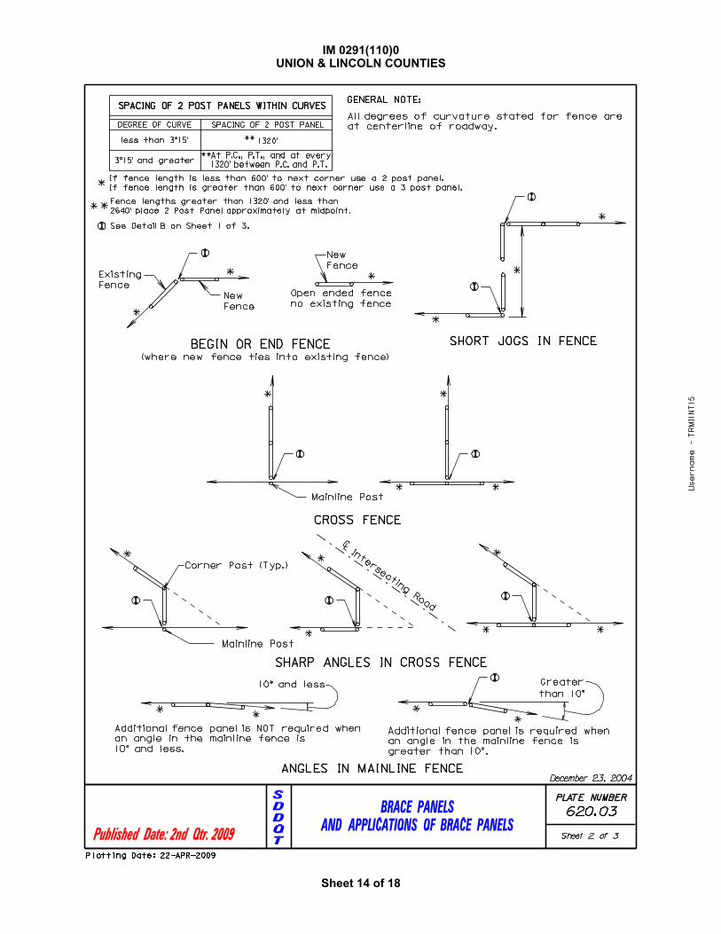
BRACE PANELS
AND APPLICATIONS OF BRACE PANELS
PLATE NUMBER
Sheet 1 of 3
620. 03
GENERAL NOTES:
4’-0
"4
’-0
"
8’-3"
12"
Diagonal
Brace Wires
ELEVATION VIEW
2 POST PANEL
4"
4"
See Detail A
DETAIL A
Direction of
Fence Pull
Place diagonal brace wire
that corresponds to direction
of fence pull.
2 turns of 11 Ga. wire
þÿ�o�r� �3� �t�u�r�n�s� �o�
to stop splitting
2"
Horizontal Wood
Brace
ELEVATION VIEW
3 POST PANEL
4’-0
"4
’-0
"
8’-3"
Diagonal
Brace Wires
4"
4"
2 turns of 11 Ga. wire
þÿ�o�r� �3� �t�u�r�n�s� �o�
to stop splittingHorizontal Wood
Brace
8’-3"
12"
See Detail A
Provide shallow notch
in brace post to accept
horizontal wood brace.
Two Post Panels shall be installed at least every 1320’ between corners.
Diagonal brace wires shall be fabricated with 4 strands of 9 Ga. galvanized wire twisted
tight. The diagonal brace wires shall be installed in accordance with the direction of the
fence pull. Two diagonal brace wires are required if fence pull is in both directions.
Two Post Panels shall be installed at any sharp vertical angle crest points and as
directed by the Engineer.
December 23, 2004
Horizontal wood braces shall consist of 4" dia. x 8’ wood posts or rough 4" x 4" x 8’ timbers.
5" Dia. x 8’-0"
Wood Posts
(Typ.)
5" Dia. x 8’-0"
Wood Posts
(Typ.)
þÿ�P�l�a�c�e� ���"� �D�i�a
dowel at center of end
of horizontal wood brace.
þÿ�D�r�i�l�l� ���"� �D�i�a�.
and in horizontal brace
for steel dowel placement.
DETAIL B
4" to 6" Space
Between Posts
3 loops of 11 Ga. wire
tightly wrapped, tied,
and stapled around
posts
Staple
(Typ.)
Usern
am
e - T
RM
I1N
T1
5
Plotting Date: 22-APR-2009
IM 0291(110)0UNION & LINCOLN COUNTIES
Sheet 13 of 18
Published Date: 2nd Qtr. 2009
S
D
D
O
T
BRACE PANELS
AND APPLICATIONS OF BRACE PANELS
PLATE NUMBER
Sheet 2 of 3
620. 03
*
*
*
*
*
*
(where new fence ties into existing fence)
SPACING OF 2 POST PANELS WITHIN CURVES
DEGREE OF CURVE SPACING OF 2 POST PANEL
less than 3^15’
3^15’ and greater
**
**
1320’
At P.C., P.T., and at every
1320’ between P.C. and P.T.
Fence lengths greater than 1320’ and less than
2640’ place 2 Post Panel approximately at midpoint.
*
Existing
Fence
New
Fence
Open ended fence
no existing fence
BEGIN OR END FENCE SHORT JOGS IN FENCE
**
If fence length is less than 600’ to next corner use a 2 post panel.
If fence length is greater than 600’ to next corner use a 3 post panel.
*
Mainline Post
*
* *
New
Fence
CROSS FENCE
SHARP ANGLES IN CROSS FENCE
* *
Mainline Post
*
*
Inte
rsectin
g R
oad
CL
Corner Post (Typ.)
**
*
GENERAL NOTE:
All degrees of curvature stated for fence are
at centerline of roadway.
ANGLES IN MAINLINE FENCE
**
Greater
than 10^
Additional fence panel is required when
an angle in the mainline fence is
greater than 10^.
*Additional fence panel is NOT required when
an angle in the mainline fence is
10^ and less.
10^ and less
December 23, 2004
See Detail B on Sheet 1 of 3.
Usern
am
e - T
RM
I1N
T1
5
Plotting Date: 22-APR-2009
IM 0291(110)0UNION & LINCOLN COUNTIES
Sheet 14 of 18

Published Date: 2nd Qtr. 2009
S
D
D
O
T
BRACE PANELS
AND APPLICATIONS OF BRACE PANELS
PLATE NUMBER
Sheet 3 of 3
620. 03
*
*
*
*
DOUBLE ENTRANCES
*
GATES
ENTRANCES AT CORNERS
If fence length is less than 600’ to next corner use a 2 post panel.
If fence length is greater than 600’ to next corner use a 3 post panel.
*
* *
* *
*
*
*
* *
*Fence type shall be same as adjacent
fence type or as directed by the Engineer.
Fence type shall be same as adjacent
fence type or as directed by the Engineer.
ENTRANCE
(NOT ON CORNER)
**
December 23, 2004
See Detail B on Sheet 1 of 3.
Usern
am
e - T
RM
I1N
T1
5
Plotting Date: 22-APR-2009
IM 0291(110)0UNION & LINCOLN COUNTIES
Sheet 15 of 18

Published Date: 2nd Qtr. 2009
S
D
D
O
T
BRACE PANEL APPLICATIONS AT STRUCTURES
* *
Structure
Eye Bolts
Structure
Eye Bolts
Stream Crossing
R.C. BOX CULVERT
OR CATTLE PASS
*
CL Roadway
Structure
Angle
BRIDGE
Wing Wall
Eye Bolt
Use 2 Post Panel
if angle exceeds
10 degrees.
PLATE NUMBER
Sheet 1 of 1
March 31, 2000
620. 04
If fence length is less than 600’ to next corner use a 2 post panel.
If fence length is greater than 600’ use a 3 post panel.*
* *
* *
STRUCTURE WITH STREAM
CROSSING FENCE
R.C. BOX CULVERT
OR CATTLE PASS
2 Post Panel
Use 3 Post Panels adjacent
to flared ends when eye bolts
are not in the wing walls.
Stream Crossing if
specified on plans
Usern
am
e - T
RM
I1N
T1
5
Plotting Date: 22-APR-2009
IM 0291(110)0UNION & LINCOLN COUNTIES
Sheet 16 of 18

Published Date: 2nd Qtr. 2009
S
D
D
O
T
FENCE ANCHORS FOR BRIDGE ABUTMENT WINGS
(WINGS 6’ AND SHORTER)
PLATE NUMBER
Sheet 1 of 1
December 23, 2004
620. 18
Eyebolt
Win
g W
all
See Structure Plans for
Wing Wall thickness
VIEW A - A
Length of Eyebolt
Min
.
þÿ �
Cast-in-place Eyebolts
shall have nut attached
EYEBOLT DETAILS
þÿ�1
�
C L
ABUTMENT WING
A
A
DETAILS FOR FENCE ANCHORS
4’’
Eyebolt (Typ. ) (See EYEBOLT DETAILS)
length and shall be embedded such that the eye of the bolt is flush with
diameter threaded eyebolt, may be used and shall be set in the concrete
in accordance with the manufacturer’s recommendations. The eyebolt
þÿ�p�l�a�c�e� �c�o�n�c�r�e�t�e� �i�n�s�e�r�t�s�,� � � �c�a�p�a�b�l�e� �o�f� �
the concrete surface. ( See Eyebolt Details ) As an alternate, cast-in-
GENERAL NOTES:
þÿ�3�.� � � � �E�y�e�b�o�l�t�s� �s�h�a�l�l� �b�e� �’�’� �d�i�a�.�
shall be incidental to the contract unit price per pound for ’’Reinforcing
6. The cost for furnishing and installing eyebolts and/or concrete inserts
The fence shall be as specified elsewhere in the plans.
1. The fence and post details shown are for illustrative purpose only.
þÿ�5�.� � � �C�a�s�t�-�i�n�-�p�l�a�c�e� �e�y�e�b�o�l�t�s� �s�h�a�l�l� �h�a�v�e�
with AASHTO M232 ( ASTM A153 ). Concrete inserts of corrosion
resistant material need not be galvanized.
shall be of sufficient length to develop its full strength. The eye of
the eyebolt shall be flush with the concrete surface.
2. Eyebolts shall be placed on all of the bridge abutment wings.
Steel’’.
4. Eyebolts, nuts, and concrete inserts shall be galvanized in accordance
Usern
am
e - T
RM
I1N
T1
5
Plotting Date: 22-APR-2009
IM 0291(110)0UNION & LINCOLN COUNTIES
Sheet 17 of 18

Published Date: 2nd Qtr. 2009
S
D
D
O
T
WIRE GATES
6" 6"
No. 9 Galv. Wire stapled
to brace panel post
+-
+-
16
20
24
30
40
5 @ 5’-10"
+-
+-
+-
+-
+-
Creosote treatment of the gate posts will not be accepted.
No. 9 Galv. Wire wrapped 3
and gate posts and stapled
to the brace panel post.
times around the brace panel
GENERAL NOTES:
PLATE NUMBER
March 31, 2000
Sheet 1 of 1
W
S S S S
3" Dia.
Post3" Dia.
Post
2" Dia. Posts or
approved commercial
type stiffeners
2 or 3 Post Panel
(as specified in plans)
Fence Type
(as specified in plans)
2 or 3 Post Panel
(as specified in plans)
Fence Type
(as specified in plans)
W
Gate Width
(ft.)
S
Post Spacing
3 @ 5’-0"
4 @ 4’-9"
4 @ 5’-9"
6 @ 6’-6"
The type of fencing in the gate shall be of the same type as
specified for the adjacent Right-of-Way fence.
All costs for furnishing and constructing the wire gate(s) shall be
incidental to the contract unit price per Ft for the respective
Right-of-Way fence bid item.
620. 20
Usern
am
e - T
RM
I1N
T1
5
Plotting Date: 22-APR-2009
IM 0291(110)0UNION & LINCOLN COUNTIES
Sheet 18 of 18