ILU IM v1.5 0713 - Palfinger
35
ILU INSTALLATION MANUAL & CHECK-OFF SHEET ECN-M0257 Rev. 1.5, Date 07-15-2013 Part #90-1313-200 PALFINGER Liftgates, LLC. 15939 Piuma Ave., Cerritos, CA 90703 Tel (888)-774-5844 Fax (562)-924-8318 PALFINGER Liftgates, LLC. 572 Whitehead Road, Trenton, NJ 08619 Tel (609)-587-4200 Fax (609)-587-4201 Visit our website at www.palfinger.com for up to date information and notifications If you received this product with damaged or missing parts, Please contact PALFINGER Liftgates at (888)-774-5844
Transcript of ILU IM v1.5 0713 - Palfinger

ILU
INSTALLATION MANUAL & CHECK-OFF SHEET
ECN-M0257 Rev. 1.5, Date 07-15-2013 Part #90-1313-200
PALFINGER Liftgates, LLC. 15939 Piuma Ave., Cerritos, CA 90703
Tel (888)-774-5844 Fax (562)-924-8318
PALFINGER Liftgates, LLC. 572 Whitehead Road, Trenton, NJ 08619
Tel (609)-587-4200 Fax (609)-587-4201
Visit our website at www.palfinger.com for up to date information and notifications
If you received this product with damaged or missing parts,
Please contact PALFINGER Liftgates at (888)-774-5844
TABLE OF CONTENTS
Revision 1.5 - 2 -
TABLE OF CONTENTS
TABLE OF CONTENTS ................................................................................................................................. 2
1 Safety Infromation .................................................................................................................... 5
2 Important Notes: ....................................................................................................................... 6
3 Chassis Dimension Sheets ...................................................................................................... 8
4 Installation Dimensions ........................................................................................................... 9
4.1 General Bed Height Ranges for ILU liftgates. ................................................................ 10
4.2 Chassis and Body Preparation ...................................................................................... 11
4.2.1 Mount frame clearance .................................................................................... 11
4.2.2 Rear sill preparation ........................................................................................ 12
5 Gate Installation ........................................................................................................................ 14
5.1 Slide rail bracket installation .......................................................................................... 14
5.2 Liftgate attachment ....................................................................................................... 15
5.3 Control power wiring setup ............................................................................................ 16
5.4 Platform installation ....................................................................................................... 17
5.4.1.1 Swing-door platform modifications ..................................................... 17
5.5 Lift arm Up-stop installation and rail stops setup ........................................................... 18
5.6 Control box installation .................................................................................................. 19
6 Gate adjusting and detailing .................................................................................................... 20
6.1 Setting B-13 lift arm sensor ........................................................................................... 20
6.2 Setting B-15 Platform sensor ........................................................................................ 21
6.3 Platform adjusting with bolts ......................................................................................... 22
7 Electrical Installation ................................................................................................................ 23
7.1 Breaker Installation ....................................................................................................... 23
7.2 Wiring schematic main battery power - Truck setup ...................................................... 24
7.3 Wiring schematic main battery power - Trailer setup ..................................................... 25
7.4 Trail charger installation ................................................................................................ 26
7.5 On/off switch installation ............................................................................................... 27
7.5.1 Truck setup ..................................................................................................... 27
7.5.2 Trailer setup .................................................................................................... 27
7.6 Control board wiring and connector setup ..................................................................... 28
7.7 Control board plug setup ............................................................................................... 29
7.8 Control box wiring (internal) .......................................................................................... 30
7.9 2 Button Remote Hand Control ..................................................................................... 30
8 Hydraulic schematic ................................................................................................................. 31
8.1 Lubrication .................................................................................................................... 32
9 Decal Placement ....................................................................................................................... 33

TABLE OF CONTENTS
Revision 1.5 - 3 -
TABLE OF FIGURES
Figure 1 Trailer dimension sheet ................................................................................................................. 8
Figure 2 Truck dimension sheet .................................................................................................................. 8
Figure 3 Installation Drawing - provided by PALFINGER Liftgates engineering department ........................ 9
Figure 4 Mounting clearance ..................................................................................................................... 11
Figure 5 Sill cut-out dimensions - rear view ............................................................................................... 12
Figure 6 Sill cut-out – sideview .................................................................................................................. 12
Figure 7 Slide rail installation ..................................................................................................................... 14
Figure 8 Liftgate installation to previous installed rails ............................................................................... 15
Figure 9 platform attachment ..................................................................................................................... 15
Figure 10 Board control power wiring connection ...................................................................................... 16
Figure 11 Main Power supply setup .......................................................................................................... 16
Figure 12 Platform installation and wiring .................................................................................................. 17
Figure 13 Installation of up-stops............................................................................................................... 18
Figure 14 Mount plate slide stops .............................................................................................................. 18
Figure 15 Control box placement............................................................................................................... 19
Figure 16 B-13 lift arm adjustment ............................................................................................................. 20
Figure 17 B-15 adjustment on platform ..................................................................................................... 21
Figure 18 Platform wiring with B-15 and controls ....................................................................................... 21
Figure 19 Circuit breaker installation ......................................................................................................... 23
Figure 20 Main wiring - truck setup ............................................................................................................ 24
Figure 21 Main wiring - trailer setup - dual pole charging system .............................................................. 25
Figure 22 Main wiring - trailer setup - single pole charging system ............................................................ 25
Figure 23 Trail charger wiring .................................................................................................................... 26
Figure 24 Cab Cut-off switch connection ................................................................................................... 27
Figure 25 On-Off setup trailer .................................................................................................................... 27
Figure 26 Control board wiring schematic ................................................................................................. 28
Figure 27 Plug setup on PC - Board .......................................................................................................... 29
Figure 28 Control box wiring schematic ..................................................................................................... 30
Figure 29 Hydraulic schematic ILU ............................................................................................................ 31
Figure 30 Grease and Lubrication points ................................................................................................... 32
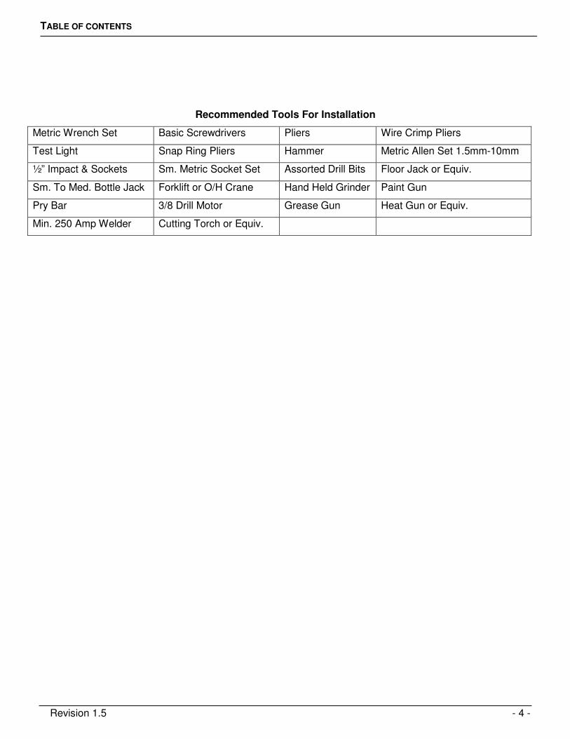
TABLE OF CONTENTS
Revision 1.5 - 4 -
Recommended Tools For Installation
Metric Wrench Set Basic Screwdrivers Pliers Wire Crimp Pliers
Test Light Snap Ring Pliers Hammer Metric Allen Set 1.5mm-10mm
½” Impact & Sockets Sm. Metric Socket Set Assorted Drill Bits Floor Jack or Equiv.
Sm. To Med. Bottle Jack Forklift or O/H Crane Hand Held Grinder Paint Gun
Pry Bar 3/8 Drill Motor Grease Gun Heat Gun or Equiv.
Min. 250 Amp Welder Cutting Torch or Equiv.
1 Safety Infromation
Revision 1.5 - 5 -
Safety Infromation 1
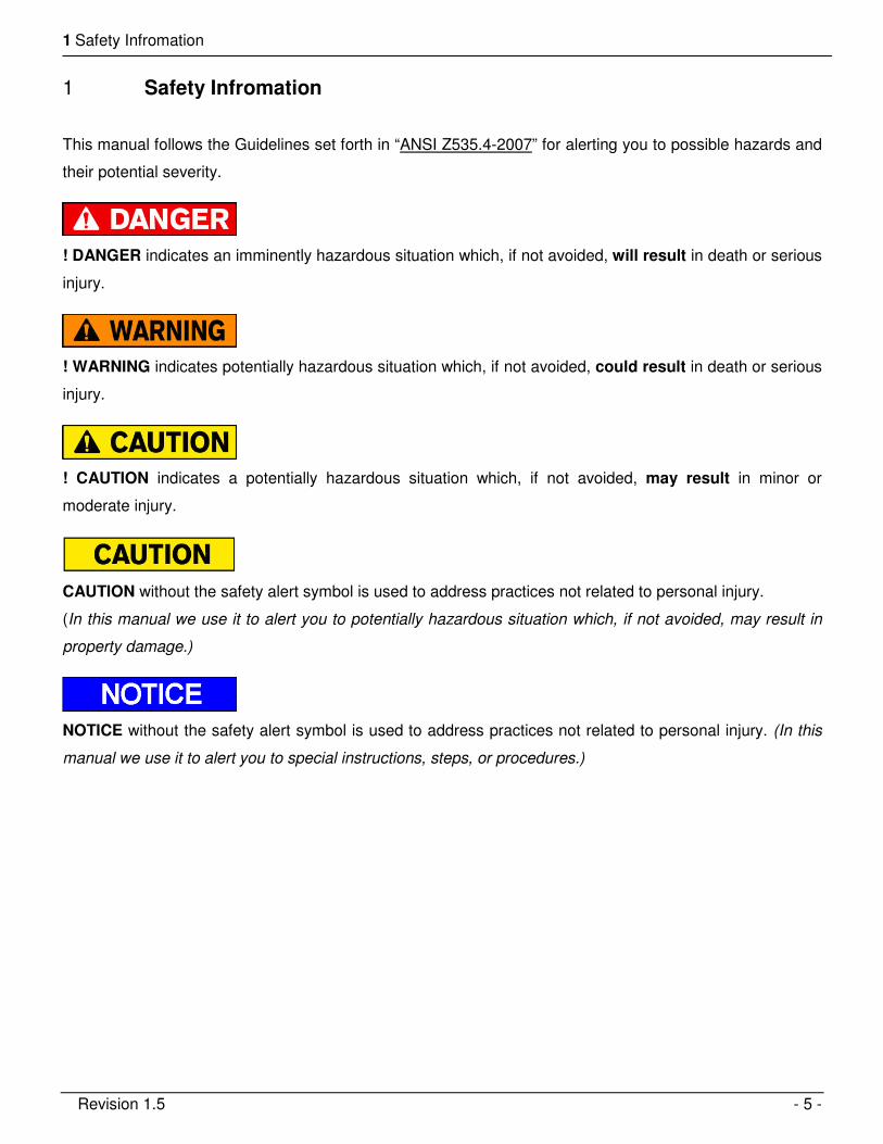
This manual follows the Guidelines set forth in “ANSI Z535.4-2007” for alerting you to possible hazards and
their potential severity.
! DANGER indicates an imminently hazardous situation which, if not avoided, will result in death or serious
injury.
! WARNING indicates potentially hazardous situation which, if not avoided, could result in death or serious
injury.
! CAUTION indicates a potentially hazardous situation which, if not avoided, may result in minor or
moderate injury.
CAUTION without the safety alert symbol is used to address practices not related to personal injury.
(In this manual we use it to alert you to potentially hazardous situation which, if not avoided, may result in
property damage.)
NOTICE without the safety alert symbol is used to address practices not related to personal injury. (In this
manual we use it to alert you to special instructions, steps, or procedures.)
2 Important Notes:
Revision 1.5 - 6 -
Important Notes: 2
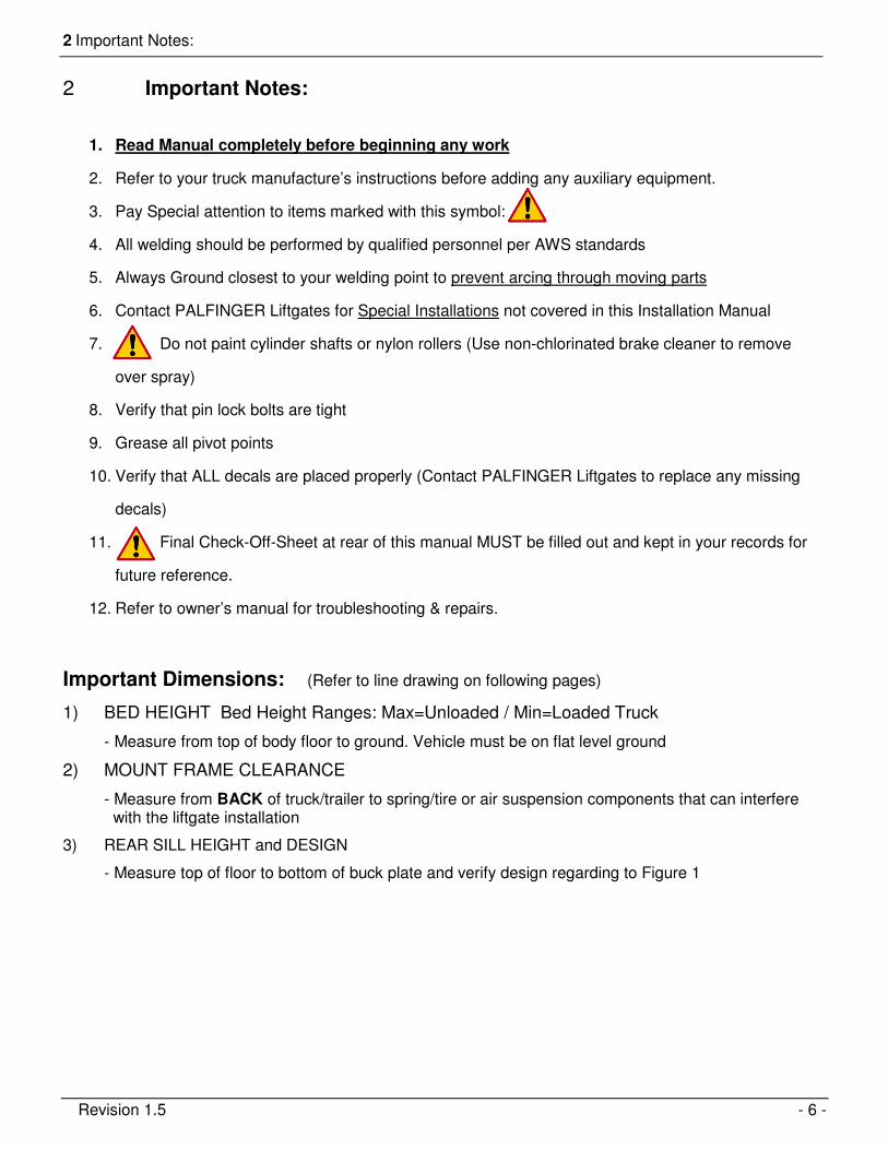
1. Read Manual completely before beginning any work
2. Refer to your truck manufacture’s instructions before adding any auxiliary equipment.
3. Pay Special attention to items marked with this symbol:
4. All welding should be performed by qualified personnel per AWS standards
5. Always Ground closest to your welding point to prevent arcing through moving parts
6. Contact PALFINGER Liftgates for Special Installations not covered in this Installation Manual
7. Do not paint cylinder shafts or nylon rollers (Use non-chlorinated brake cleaner to remove
over spray)
8. Verify that pin lock bolts are tight
9. Grease all pivot points
10. Verify that ALL decals are placed properly (Contact PALFINGER Liftgates to replace any missing
decals)
11. Final Check-Off-Sheet at rear of this manual MUST be filled out and kept in your records for
future reference.
12. Refer to owner’s manual for troubleshooting & repairs.
Important Dimensions: (Refer to line drawing on following pages)
1) BED HEIGHT Bed Height Ranges: Max=Unloaded / Min=Loaded Truck
- Measure from top of body floor to ground. Vehicle must be on flat level ground
2) MOUNT FRAME CLEARANCE
- Measure from BACK of truck/trailer to spring/tire or air suspension components that can interfere with the liftgate installation
3) REAR SILL HEIGHT and DESIGN
- Measure top of floor to bottom of buck plate and verify design regarding to Figure 1
2 Important Notes:
Revision 1.5 - 7 -
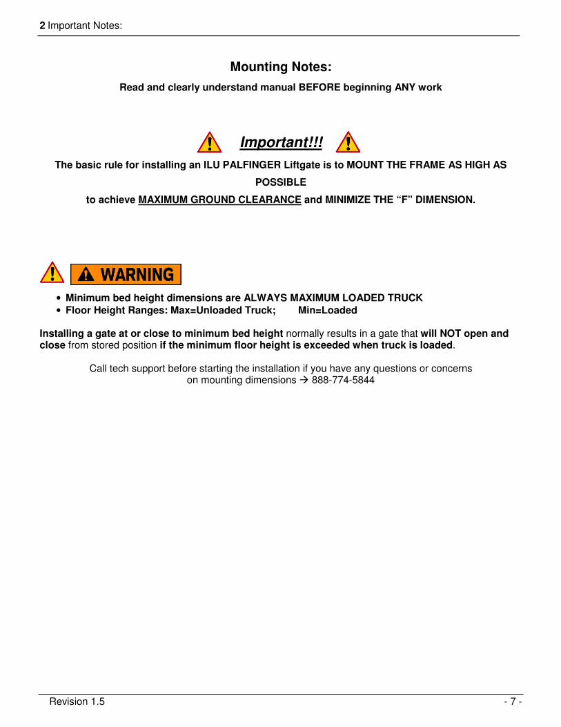
Mounting Notes:
Read and clearly understand manual BEFORE beginning ANY work
Important!!!
The basic rule for installing an ILU PALFINGER Liftgate is to MOUNT THE FRAME AS HIGH AS
POSSIBLE
to achieve MAXIMUM GROUND CLEARANCE and MINIMIZE THE “F” DIMENSION.
• Minimum bed height dimensions are ALWAYS MAXIMUM LOADED TRUCK
• Floor Height Ranges: Max=Unloaded Truck; Min=Loaded Installing a gate at or close to minimum bed height normally results in a gate that will NOT open and close from stored position if the minimum floor height is exceeded when truck is loaded.
Call tech support before starting the installation if you have any questions or concerns on mounting dimensions � 888-774-5844
3 Chassis Dimension SheetsChassis Dimension Sheets
Revision 1.5 - 8 -
Chassis Dimension Sheets 3
D
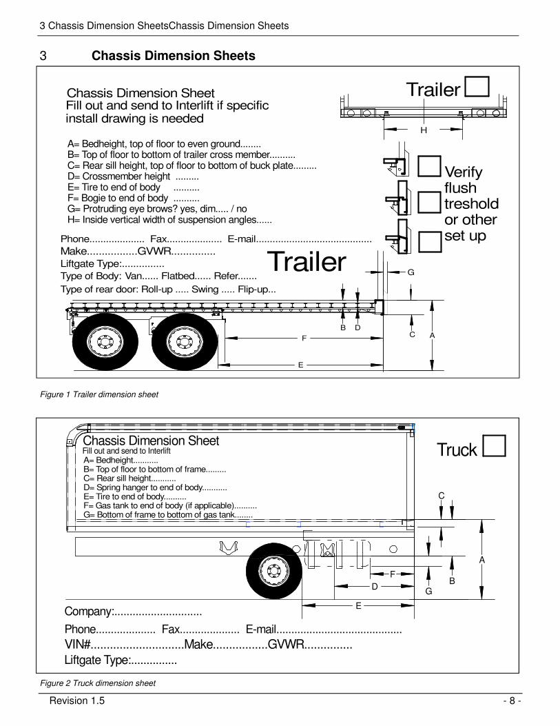
Fill out and send to Interlift if specific install drawing is needed
A= Bedheight, top of floor to even ground........B= Top of floor to bottom of trailer cross member..........C= Rear sill height, top of floor to bottom of buck plate.........D= Crossmember height .........E= Tire to end of body ..........F= Bogie to end of body ..........G= Protruding eye brows? yes, dim..... / noH= Inside vertical width of suspension angles......
Liftgate Type:...............
Type of Body: Van...... Flatbed...... Refer.......
Make.................GVWR...............
Chassis Dimension Sheet
Phone.................... Fax.................... E-mail..........................................
Type of rear door: Roll-up ..... Swing ..... Flip-up...
Trailer
Trailer
H
Verify flush tresholdor otherset up
A
E
F
DBC
G
Figure 1 Trailer dimension sheet
me
A= Bedheight...........B= Top of floor to bottom of frame.........C= Rear sill height...........D= Spring hanger to end of body...........E= Tire to end of body..........F= Gas tank to end of body (if applicable)..........G= Bottom of frame to bottom of gas tank........
F
D
E
GB
A
C
Company:.............................
Liftgate Type:...............
VIN#.............................Make.................GVWR...............
Chassis Dimension SheetFill out and send to Interlift
Phone.................... Fax.................... E-mail..........................................
Truck
Figure 2 Truck dimension sheet
4 Installation Dimensions
Revision 1.5 - 9 -
Installation Dimensions 4
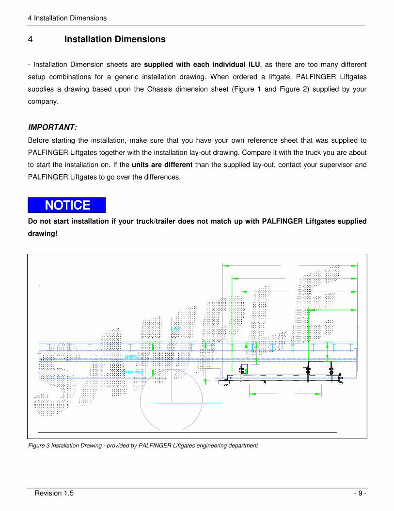
- Installation Dimension sheets are supplied with each individual ILU, as there are too many different
setup combinations for a generic installation drawing. When ordered a liftgate, PALFINGER Liftgates
supplies a drawing based upon the Chassis dimension sheet (Figure 1 and Figure 2) supplied by your
company.
IMPORTANT:
Before starting the installation, make sure that you have your own reference sheet that was supplied to
PALFINGER Liftgates together with the installation lay-out drawing. Compare it with the truck you are about
to start the installation on. If the units are different than the supplied lay-out, contact your supervisor and
PALFINGER Liftgates to go over the differences.
Do not start installation if your truck/trailer does not match up with PALFINGER Liftgates supplied
drawing!
Figure 3 Installation Drawing - provided by PALFINGER Liftgates engineering department

4 Installation Dimensions
Revision 1.5 - 10 -
4.1 General Bed Height Ranges for ILU liftgates.
Minimum bed height is when truck/trailer is loaded to MAX GVW (all dimensions in inches)
ILU 40-50 800mm arm 36”- 56”
4 Installation Dimensions
Revision 1.5 - 11 -
4.2 Chassis and Body Preparation
4.2.1 Mount frame clearance
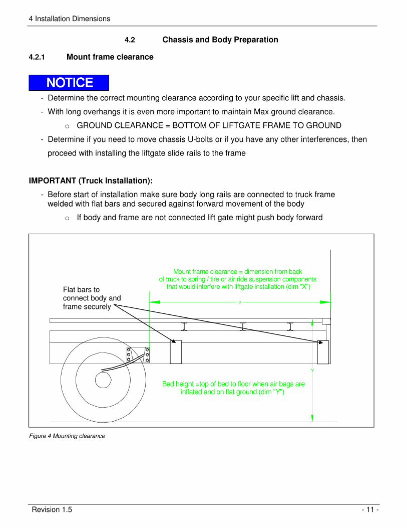
- Determine the correct mounting clearance according to your specific lift and chassis.
- With long overhangs it is even more important to maintain Max ground clearance.
o GROUND CLEARANCE = BOTTOM OF LIFTGATE FRAME TO GROUND
- Determine if you need to move chassis U-bolts or if you have any other interferences, then
proceed with installing the liftgate slide rails to the frame
IMPORTANT (Truck Installation):
- Before start of installation make sure body long rails are connected to truck frame welded with flat bars and secured against forward movement of the body
o If body and frame are not connected lift gate might push body forward
Bed height =top of bed to floor when air bags areinflated and on flat ground (dim "Y")
Mount frame clearance = dimension from back of truck to spring / tire or air ride suspension components
that would interfere with liftgate installation (dim "X")
Y
X
Figure 4 Mounting clearance
Flat bars to connect body and frame securely
4 Installation Dimensions
Revision 1.5 - 12 -
Eyebrow cut out to clear platform
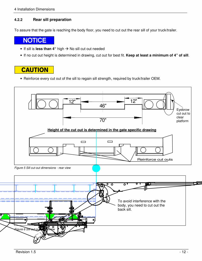
4.2.2 Rear sill preparation
To assure that the gate is reaching the body floor, you need to cut out the rear sill of your truck/trailer.
• If sill is less than 4“ high � No sill cut out needed
• If no cut out height is determined in drawing, cut out for best fit. Keep at least a minimum of 4” of sill.
• Reinforce every cut out of the sill to regain sill strength, required by truck/trailer OEM.
46"12" 12"
70"
Reinforce cut outs
Figure 5 Sill cut-out dimensions - rear view
Figure 6 Sill cut-out – sideview
To avoid interference with the body, you need to cut out the back sill.
Height of the cut out is determined in the gate specific drawing
4 Installation Dimensions
Revision 1.5 - 13 -
• On trailers, you have to check the eyebrow clearance, and in case of interference cut eyebrow down until platform clears.
• The eyebrow cut out can be done when gate and platform are installed and you raise up gate for the first time. That gives the opportunity to keep as much of the eyebrow as possible to keep rear frame strength.
IMPORTANT!!!
• A proper preparation of the truck/trailer sets the basics for a safe, clear and fast installation process and assures a proper function of the lift gate without damage to truck/trailer or lift gate.

5 Gate Installation
Revision 1.5 - 14 -
Gate Installation 5
Never work under mount frame or platform without safety supports
5.1 Slide rail bracket installation
Figure 7 Slide rail installation
1) Make sure the specific install drawing sent with the liftgate matches the truck and gate you are about to install.
2) Install the slider rail frame according to drawing sent with the gate. Weld brackets with 2 x 2” of ¼”
welds on each side for adjustment purposes
3) When gate is completely installed and tested for proper function weld a 100% around the brackets to assure a save and secure connection of gate- and truck frame.
ADD STEEL BACKER PLATEIF MOUNT BRACKET CAN NOTBE WELDED 100%.
5 Gate Installation
Revision 1.5 - 15 -
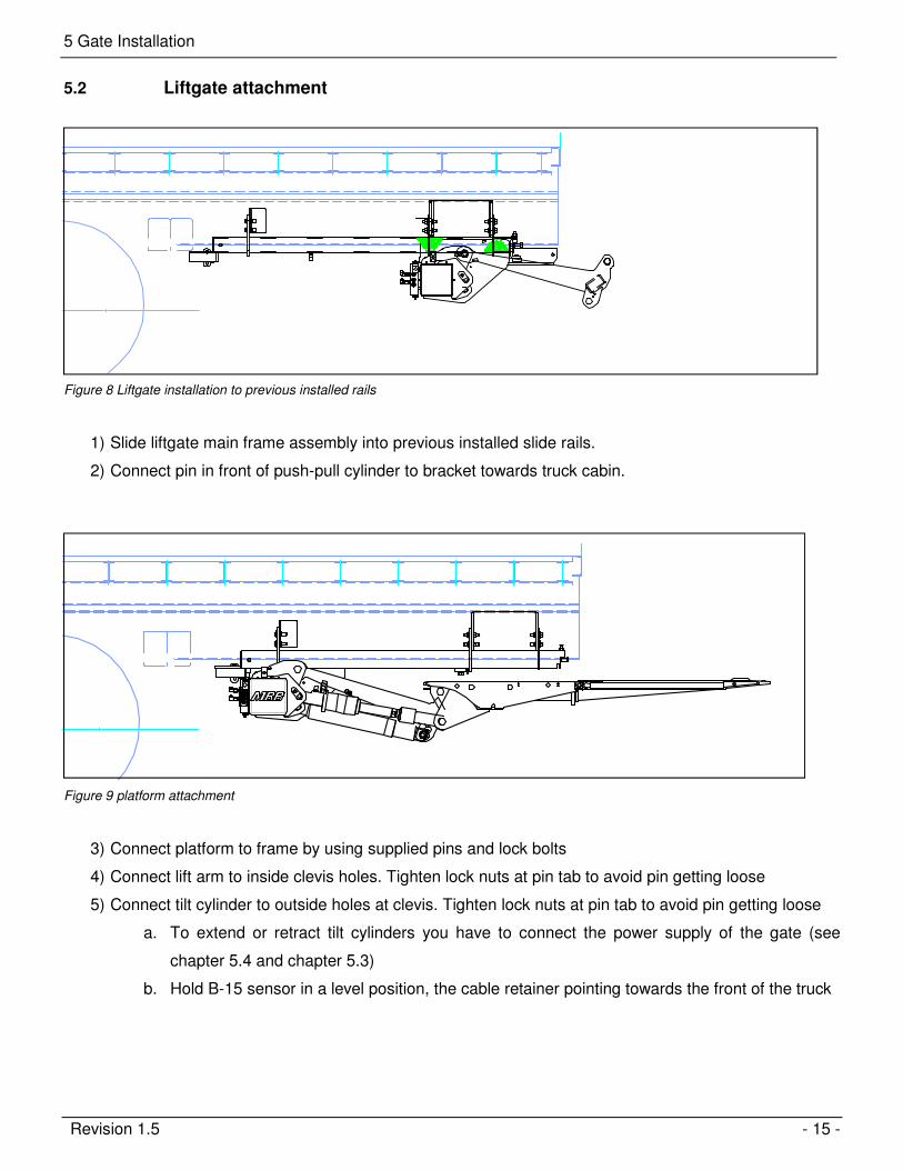
5.2 Liftgate attachment
Figure 8 Liftgate installation to previous installed rails
1) Slide liftgate main frame assembly into previous installed slide rails.
2) Connect pin in front of push-pull cylinder to bracket towards truck cabin.
Figure 9 platform attachment
3) Connect platform to frame by using supplied pins and lock bolts
4) Connect lift arm to inside clevis holes. Tighten lock nuts at pin tab to avoid pin getting loose
5) Connect tilt cylinder to outside holes at clevis. Tighten lock nuts at pin tab to avoid pin getting loose
a. To extend or retract tilt cylinders you have to connect the power supply of the gate (see
chapter 5.4 and chapter 5.3)
b. Hold B-15 sensor in a level position, the cable retainer pointing towards the front of the truck

5 Gate Installation
Revision 1.5 - 16 -
5.3 Control power wiring setup
To maintain the best possible power supply, install the auxiliary batteries as close as possible to the gate.
- Truck installations might not have an auxiliary battery kit (PALFINGER Liftgates always recommends a kit). In this
case you have to run the control power straight off the truck battery. - Trailer installations always have a trailer battery kit (at least 2 batteries recommended)
Connect your control power to the positive (#2 & #4) and the negative (#1 & gr/ye) post of the batteries.
Control Power 4-Wire CableTruck Application-Always wire to truck batteryTrailer Application-wire to trailer battery
+ -
20 AmpIn-LineFuse
+ -
Wires marked#2;#4 (Black)go to hot,#1 and green/yellowgo to ground
PC-board
2 27
15 Amp fuses
J1 Plug
#2 #4+ +E E- -
gr/ye #1
J2 Plug
Figure 10 Board control power wiring connection
Gro
und C
able
Groundat trailer frame
(Third Battery Shownfor heavy applications Only)
+-
Liftgate Mount Frame
Main Truck Batteries
2 G
a. Lift
gate
Pow
er
Cable
Ground
+-
+ -
To Ignition Switch
Ground
Aux. Batteries
BatteryIsolator
+ -
(if applicable)
CircuitBreaker
+-
CircuitBreaker
Tractor -TrailerPlug
Figure 11 Main Power supply setup
5 Gate Installation
Revision 1.5 - 17 -
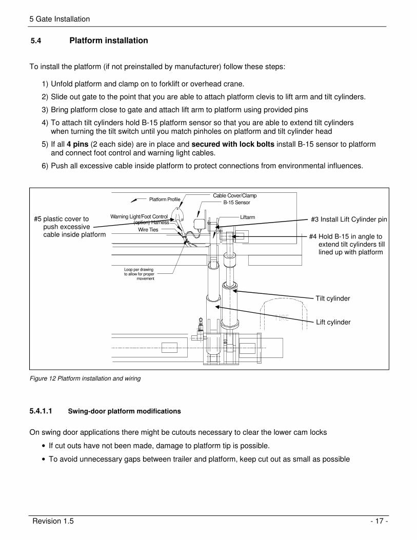
5.4 Platform installation
To install the platform (if not preinstalled by manufacturer) follow these steps:
1) Unfold platform and clamp on to forklift or overhead crane.
2) Slide out gate to the point that you are able to attach platform clevis to lift arm and tilt cylinders.
3) Bring platform close to gate and attach lift arm to platform using provided pins
4) To attach tilt cylinders hold B-15 platform sensor so that you are able to extend tilt cylinders when turning the tilt switch until you match pinholes on platform and tilt cylinder head
5) If all 4 pins (2 each side) are in place and secured with lock bolts install B-15 sensor to platform and connect foot control and warning light cables.
6) Push all excessive cable inside platform to protect connections from environmental influences.
TIRE
Cable Cover/Clamp
B-15 Sensor
Liftarm
Platform Profile
Wire Ties
Warning Light/Foot Control (option) Harness
Loop per drawing to allow for proper
movement
Figure 12 Platform installation and wiring
5.4.1.1 Swing-door platform modifications
On swing door applications there might be cutouts necessary to clear the lower cam locks
• If cut outs have not been made, damage to platform tip is possible.
• To avoid unnecessary gaps between trailer and platform, keep cut out as small as possible
#3 Install Lift Cylinder pin
#4 Hold B-15 in angle to extend tilt cylinders till lined up with platform
#5 plastic cover to push excessive cable inside platform
Tilt cylinder
Lift cylinder
5 Gate Installation
Revision 1.5 - 18 -
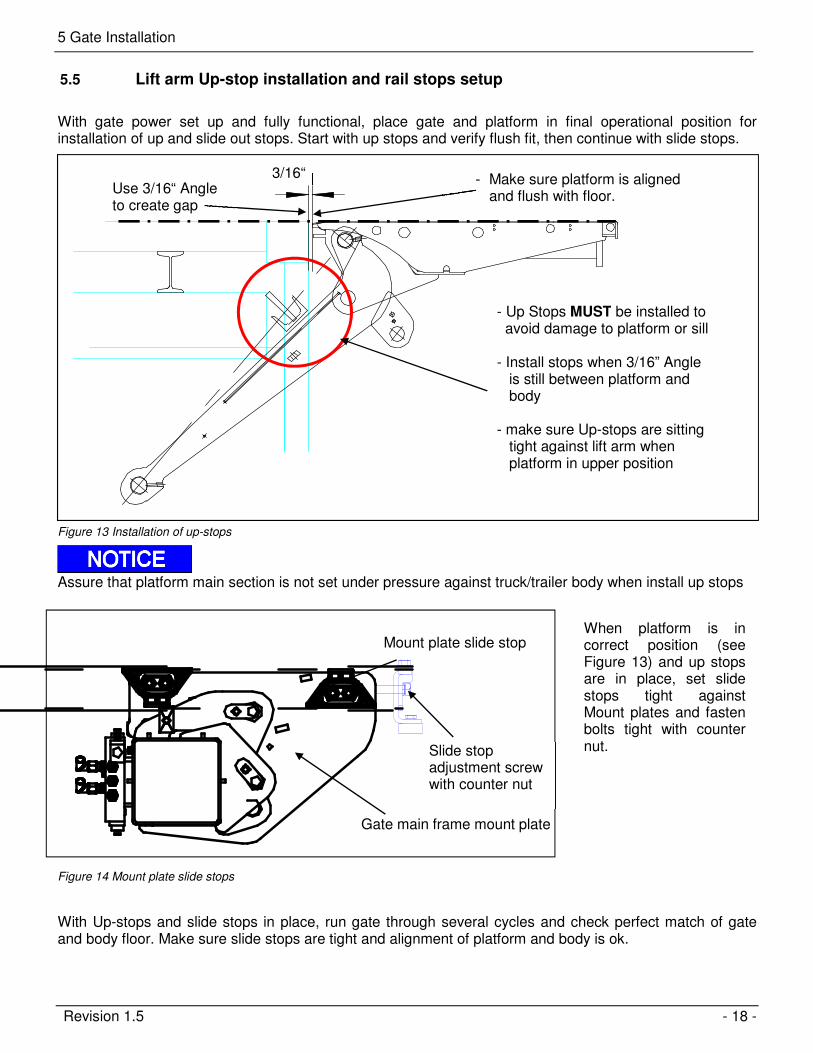
5.5 Lift arm Up-stop installation and rail stops setup
With gate power set up and fully functional, place gate and platform in final operational position for installation of up and slide out stops. Start with up stops and verify flush fit, then continue with slide stops.
Figure 13 Installation of up-stops
Assure that platform main section is not set under pressure against truck/trailer body when install up stops
With Up-stops and slide stops in place, run gate through several cycles and check perfect match of gate and body floor. Make sure slide stops are tight and alignment of platform and body is ok.
- Make sure platform is aligned and flush with floor.
- Up Stops MUST be installed to avoid damage to platform or sill - Install stops when 3/16” Angle is still between platform and body - make sure Up-stops are sitting tight against lift arm when platform in upper position
3/16“ Use 3/16“ Angle to create gap
Gate main frame mount plate
Mount plate slide stop When platform is in correct position (see Figure 13) and up stops are in place, set slide stops tight against Mount plates and fasten bolts tight with counter nut.
Figure 14 Mount plate slide stops
Slide stop adjustment screw with counter nut
5 Gate Installation
Revision 1.5 - 19 -
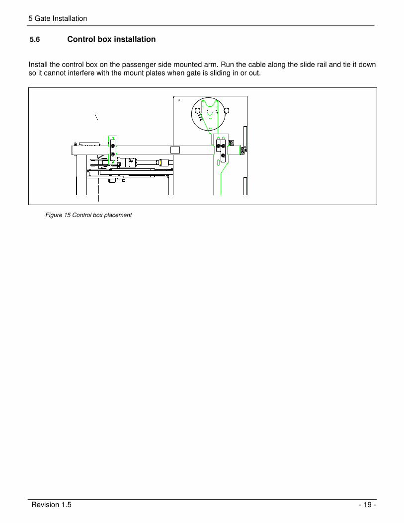
5.6 Control box installation
Install the control box on the passenger side mounted arm. Run the cable along the slide rail and tie it down so it cannot interfere with the mount plates when gate is sliding in or out.
Figure 15 Control box placement
6 Gate adjusting and detailing
Revision 1.5 - 20 -
Gate adjusting and detailing 6
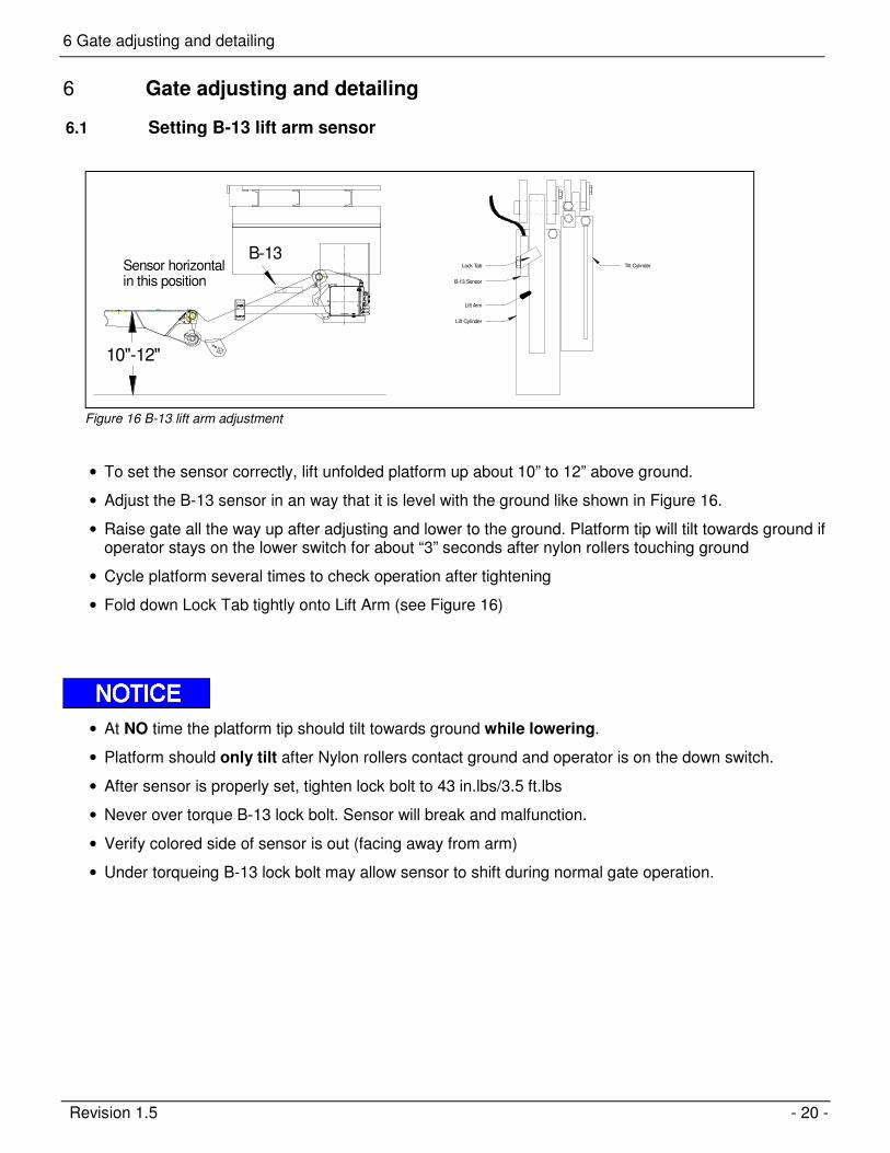
6.1 Setting B-13 lift arm sensor
10"-12"
Sensor horizontal in this position
B-13
Lift Arm
Lift Cylinder
B-13 Sensor
Lock Tab Tilt Cylinder
Figure 16 B-13 lift arm adjustment
• To set the sensor correctly, lift unfolded platform up about 10” to 12” above ground.
• Adjust the B-13 sensor in an way that it is level with the ground like shown in Figure 16.
• Raise gate all the way up after adjusting and lower to the ground. Platform tip will tilt towards ground if operator stays on the lower switch for about “3” seconds after nylon rollers touching ground
• Cycle platform several times to check operation after tightening
• Fold down Lock Tab tightly onto Lift Arm (see Figure 16)
• At NO time the platform tip should tilt towards ground while lowering.
• Platform should only tilt after Nylon rollers contact ground and operator is on the down switch.
• After sensor is properly set, tighten lock bolt to 43 in.lbs/3.5 ft.lbs
• Never over torque B-13 lock bolt. Sensor will break and malfunction.
• Verify colored side of sensor is out (facing away from arm)
• Under torqueing B-13 lock bolt may allow sensor to shift during normal gate operation.

6 Gate adjusting and detailing
Revision 1.5 - 21 -
6.2 Setting B-15 Platform sensor
Figure 17 B-15 adjustment on platform
• Mount the platform sensor B-15 to the right-hand side of the platform as shown in Figure 18. Make
sure to loop wire around to give it enough slack in normal operation and route clear of any pinch
points.
• Verify B-15 is set correct, when cable restrainer is parallel with platform surface.
• B-15 is working correct if platform finds preset level position while tilting up form ground
position
• If platform is only lifting, without leveling out - battery power supply is low, check and charge battery.
(On trucks – start truck and run in high idle for 5 – 10 Min)
Cable Cover/Clamp
B-15 Sensor
Liftarm
Platform Profile
Wire Ties
Warning Light/Foot Control (option) Harness
Figure 18 Platform wiring with B-15 and controls
6 Gate adjusting and detailing
Revision 1.5 - 22 -
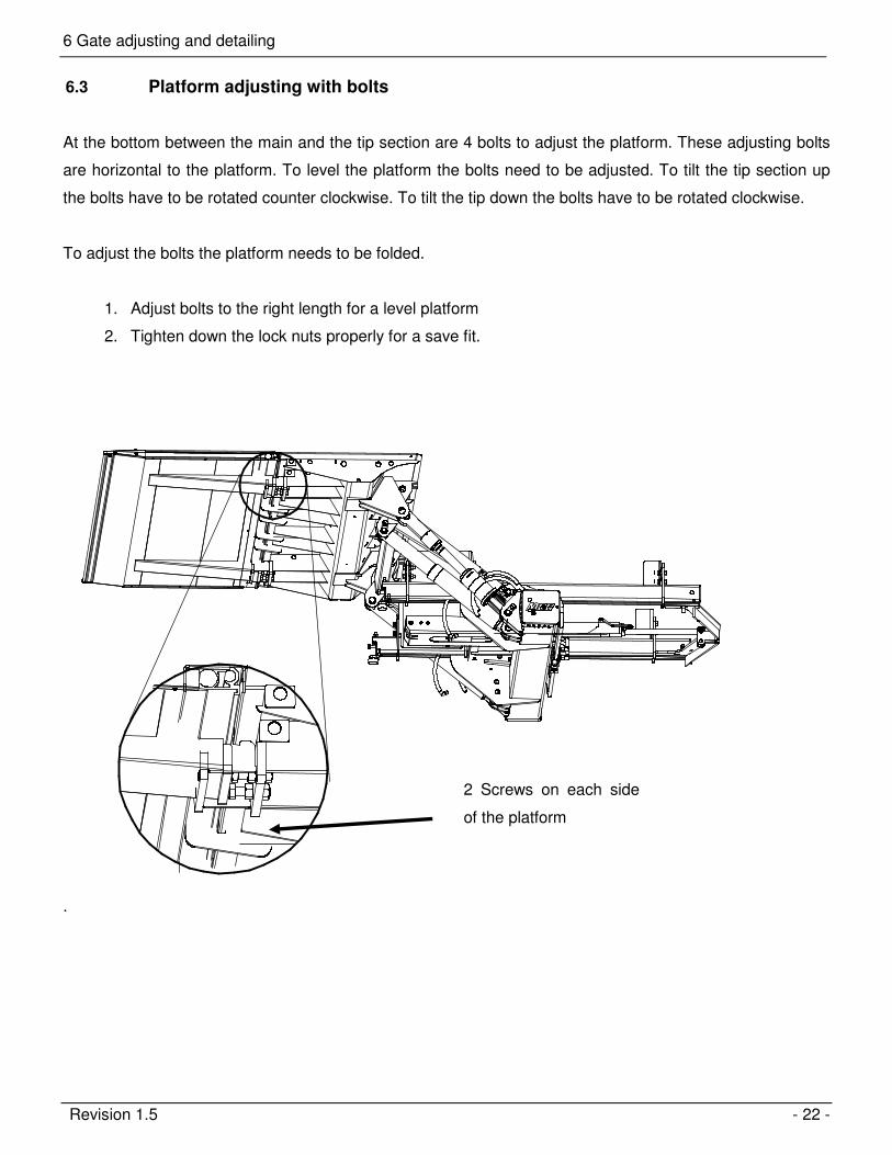
6.3 Platform adjusting with bolts
At the bottom between the main and the tip section are 4 bolts to adjust the platform. These adjusting bolts
are horizontal to the platform. To level the platform the bolts need to be adjusted. To tilt the tip section up
the bolts have to be rotated counter clockwise. To tilt the tip down the bolts have to be rotated clockwise.
To adjust the bolts the platform needs to be folded.
1. Adjust bolts to the right length for a level platform
2. Tighten down the lock nuts properly for a save fit.
.
2 Screws on each side
of the platform
7 Electrical Installation
Revision 1.5 - 23 -
Electrical Installation 7
When performing electrical installation, be certain to install and secure everything in a way where it is not
subject to damage from moving parts, sharp edges, exhaust systems, etc.
• ANY deviation from PALFINGER Liftgates’ recommended power setup (see 7 Electrical
Installation)
will void warranty and product liability unless you have a written confirmation by PALFINGER
Liftgates that allows you to do specific changes.
• Never tie the power cables to gas or diesel lines on trucks – it is a fire hazard.
• Never exceed rating of existing fuses located at the battery, control board and/or the pump and motor which may result in serious damage to the equipment.
• Never jump the 150 Amp circuit breaker at the batteries unless otherwise instructed by the PALFINGER Liftgates technical support center
• Assure all connections are tight and securely fastened
• Heat shrink any connection to all cables.
• Never secure a cable in a way where it can make contact with other wiring, brake-, fuel- or air- lines etc. or get pinched against other objects.
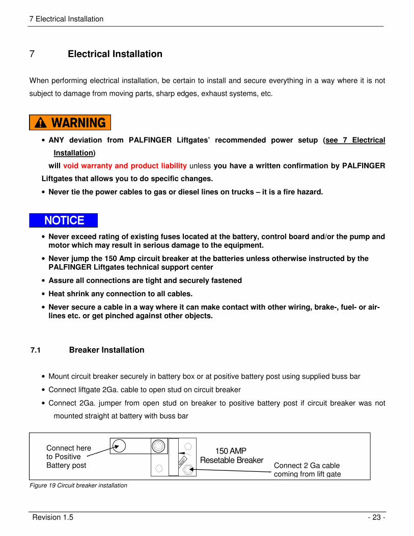
7.1 Breaker Installation
• Mount circuit breaker securely in battery box or at positive battery post using supplied buss bar
• Connect liftgate 2Ga. cable to open stud on circuit breaker
• Connect 2Ga. jumper from open stud on breaker to positive battery post if circuit breaker was not
mounted straight at battery with buss bar
150 AMP Resetable Breaker
RESE
T
Figure 19 Circuit breaker installation
Connect 2 Ga cable coming from lift gate
Connect here to Positive Battery post

7 Electrical Installation
Revision 1.5 - 24 -
7.2 Wiring schematic main battery power - Truck setup
Gro
und C
able
Ground
(Third Battery Shownfor heavy applications Only)
+-
Liftgate Mount FrameMain Truck Batteries
2 G
a. Lift
gate
Pow
er
Cable
Ground
+-
+ -
To Ignition Switch
Ground
Aux. Batteries (if applicable)
BatteryIsolator
+ -
(if applicable)
CircuitBreaker
+-
CircuitBreaker
Figure 20 Main wiring - truck setup

7 Electrical Installation
Revision 1.5 - 25 -
7.3 Wiring schematic main battery power - Trailer setup
Gro
und C
able
Ground
(Third Battery Shownfor heavy applications Only)
+-
Liftgate Mount Frame
2 G
a. Lift
gate
Pow
er
Cable
Ground
+-
Aux. Batteries
+-
Figure 21 Main wiring - trailer setup - dual pole charging system
Gro
und C
able
Ground
(Third Battery Shownfor heavy applications Only)
+-
Liftgate Mount Frame2 G
a. Lift
gate
Pow
er
Cable
Ground
+-
Aux. Batteries
+-
Ground
Figure 22 Main wiring - trailer setup - single pole charging system
Dual pole plug
Single pole plug
7 Electrical Installation
Revision 1.5 - 26 -
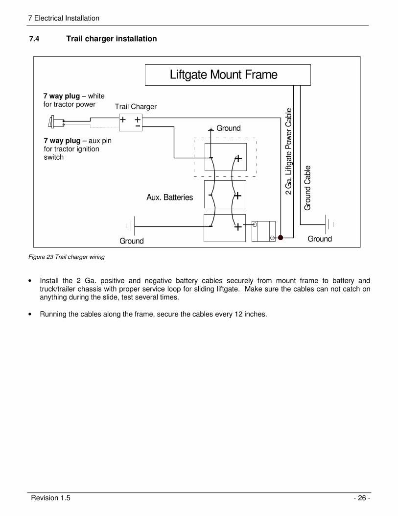
7.4 Trail charger installation
Gro
und C
able
Ground
+-
Liftgate Mount Frame
2 G
a. Lift
gate
Pow
er
Cable
Ground
+-
Aux. Batteries
+-
Ground
+-
+
Figure 23 Trail charger wiring
• Install the 2 Ga. positive and negative battery cables securely from mount frame to battery and truck/trailer chassis with proper service loop for sliding liftgate. Make sure the cables can not catch on anything during the slide, test several times.
• Running the cables along the frame, secure the cables every 12 inches.
Trail Charger
7 way plug – aux pin for tractor ignition switch
7 way plug – white for tractor power
7 Electrical Installation
Revision 1.5 - 27 -
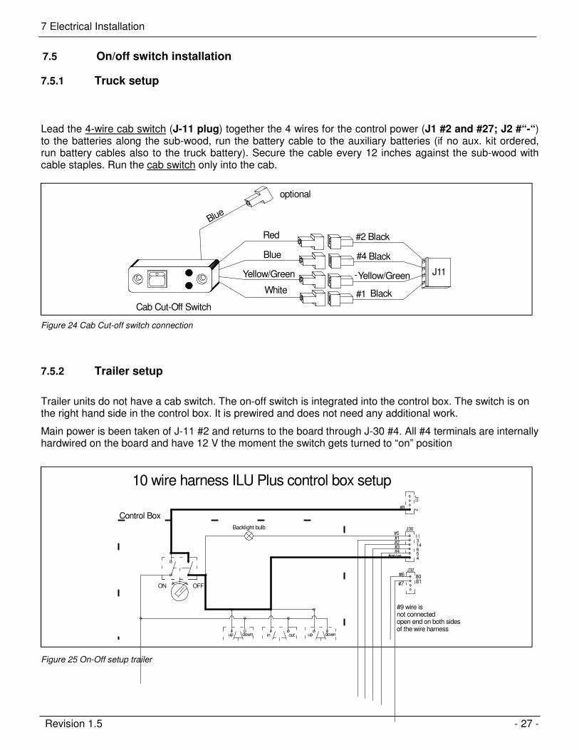
7.5 On/off switch installation
7.5.1 Truck setup
Lead the 4-wire cab switch (J-11 plug) together the 4 wires for the control power (J1 #2 and #27; J2 #“-“) to the batteries along the sub-wood, run the battery cable to the auxiliary batteries (if no aux. kit ordered, run battery cables also to the truck battery). Secure the cable every 12 inches against the sub-wood with cable staples. Run the cab switch only into the cab.
Cab Cut-Off Switch
Blue
Black
Black
Yellow/GreenYellow/Green
#2
#4
#1
-
Red
J11
Black
Blue
optional
White
Figure 24 Cab Cut-off switch connection
7.5.2 Trailer setup
Trailer units do not have a cab switch. The on-off switch is integrated into the control box. The switch is on the right hand side in the control box. It is prewired and does not need any additional work.
Main power is been taken of J-11 #2 and returns to the board through J-30 #4. All #4 terminals are internally hardwired on the board and have 12 V the moment the switch gets turned to “on” position
OFFON
2
up down in out up down
J32
8180
(-)#5#1#2#3#4
#gn/ye
314654
#7
#6
#8
J30
J11
Backlight bulb
Control Box
#9 wire is not connectedopen end on both sidesof the wire harness
10 wire harness ILU Plus control box setup
Figure 25 On-Off setup trailer
7 Electrical Installation
Revision 1.5 - 28 -
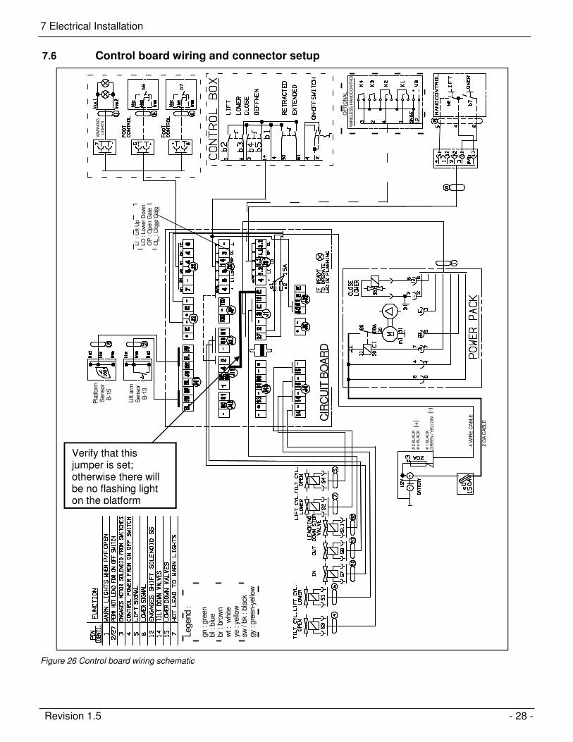
7.6 Control board wiring and connector setup
2 G
A C
AB
LE
4 W
IRE
CA
BLE
# 2
BLA
CK
# 4
BLA
CK
# 1
BLA
CK
GR
EE
N / Y
ELLO
W
(+)
(-)
CIR
CU
IT B
OA
RD
WIR
ELE
SS
HA
ND
CO
NT
RO
L
OP
TIO
NA
L
Legend
:
gn : g
reen
bl :
blu
ebr
: bro
wn
wt : w
hite
ye : y
ello
wsw
/ b
k : bla
ckgy
: gre
en-y
ello
w
LI : L
ift U
pLO
: L
ow
er
Dow
nO
P : O
pen G
ate
CL : C
lose
Gate
WA
RN
ING
LIG
HT
S
Pla
tform
S
enso
r B
-15
Lift
arm
S
enso
r B
-13
Figure 26 Control board wiring schematic
Verify that this jumper is set; otherwise there will be no flashing light on the platform
7 Electrical Installation
Revision 1.5 - 29 -
7.7 Control board plug setup
B13 LIFT ARM B15 PLATFORM FOOT CONTROL
WARNING LIGHTS
CAB ON-OFFSWITCH TRUCK
ILUK
CONTROL BOX
HAND REMOTE
JUMPS to
J 11 # 4
POWER PACK
GROUND for PC BOARD(green/yellow and black # 1)
CIRCUIT BOARD K+
SECONDARY HARNESSfor SLIDE function
POSITIVE for PC BOARD(black #2 to 2 and black # 4 to 27)
CYLINDERSLIFT 15 (2 ea)TILT 14 (2ea) PUSH-PULL
CYLINDERS
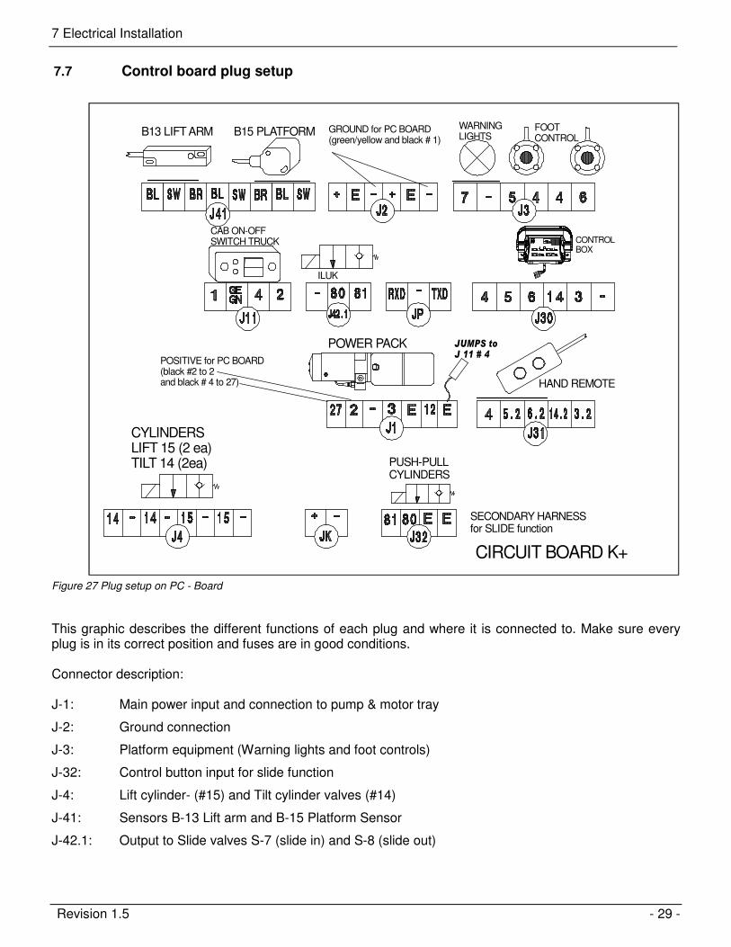
Figure 27 Plug setup on PC - Board
This graphic describes the different functions of each plug and where it is connected to. Make sure every plug is in its correct position and fuses are in good conditions. Connector description: J-1: Main power input and connection to pump & motor tray
J-2: Ground connection
J-3: Platform equipment (Warning lights and foot controls)
J-32: Control button input for slide function
J-4: Lift cylinder- (#15) and Tilt cylinder valves (#14)
J-41: Sensors B-13 Lift arm and B-15 Platform Sensor
J-42.1: Output to Slide valves S-7 (slide in) and S-8 (slide out)
7 Electrical Installation
Revision 1.5 - 30 -
7.8 Control box wiring (internal)
OFFON
POS #4
#3
2
Hand Control
TILT SLIDE LIFT
up down in out up down
#1 #2 #7 #6 #4 #3
J32
8180
(-)#5#1#2#3#4
#gn/ye
314654
#7
#6
#8
#gn/ye
J30
J11
Backlight bulb
Control Box
#9 wire is not connectedopen end on both sidesof the wire harness
10 wire harness ILU Plus control box setup
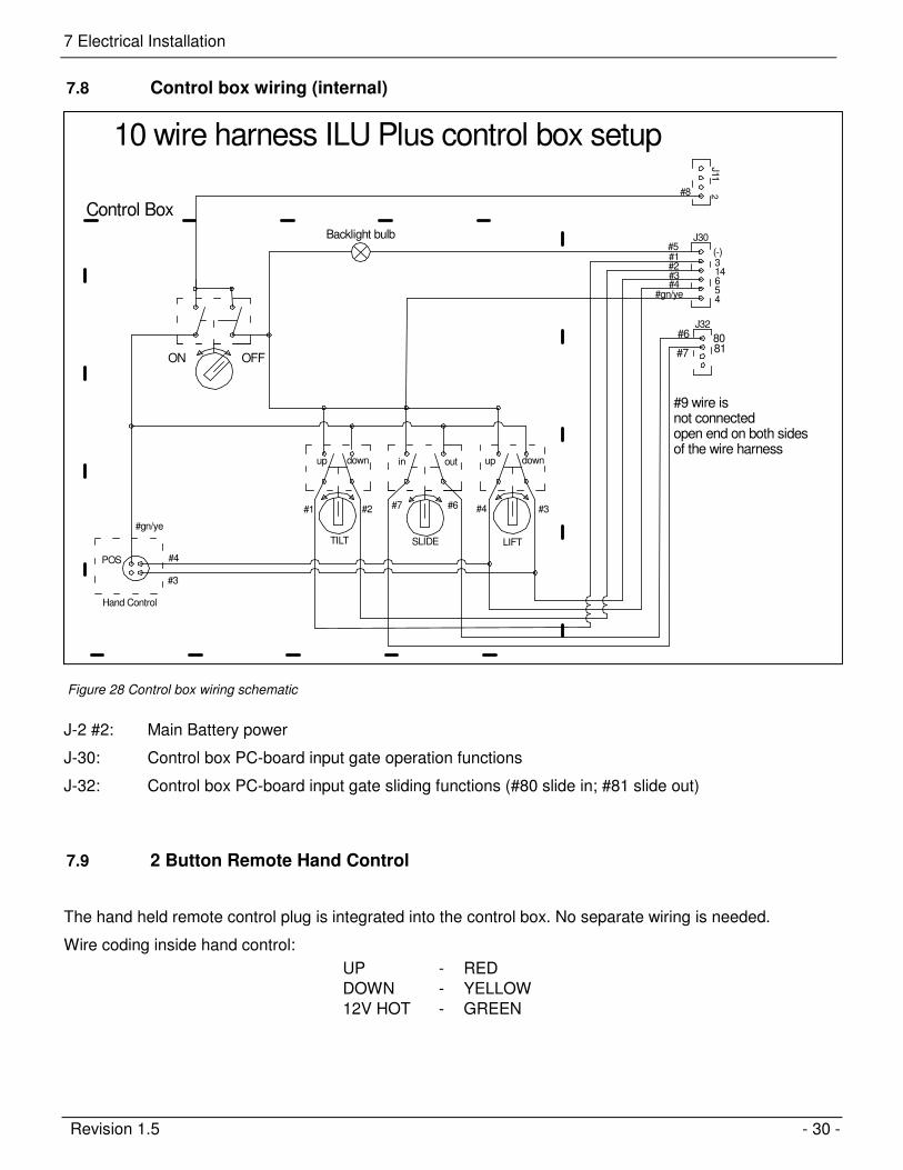
Figure 28 Control box wiring schematic
J-2 #2: Main Battery power
J-30: Control box PC-board input gate operation functions
J-32: Control box PC-board input gate sliding functions (#80 slide in; #81 slide out)
7.9 2 Button Remote Hand Control
The hand held remote control plug is integrated into the control box. No separate wiring is needed.
Wire coding inside hand control:
UP - RED
DOWN - YELLOW
12V HOT - GREEN
8 Hydraulic schematic
Revision 1.5 - 31 -
Hydraulic schematic 8
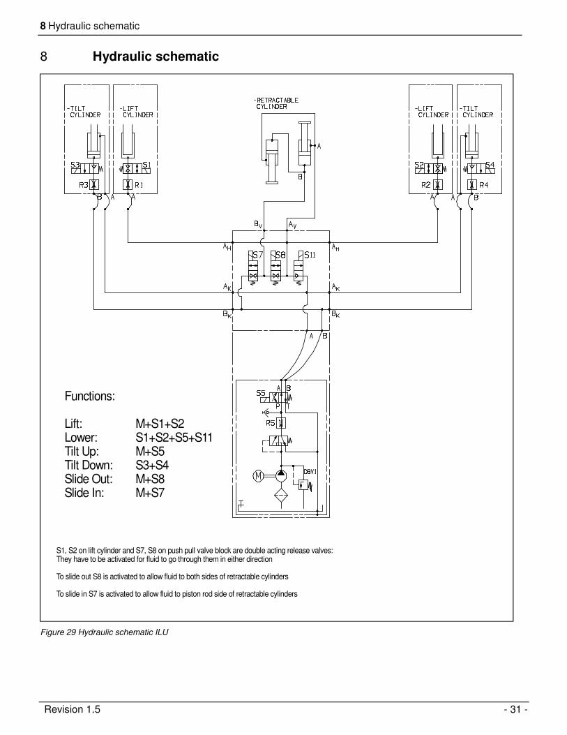
S1, S2 on lift cylinder and S7, S8 on push pull valve block are double acting release valves:They have to be activated for fluid to go through them in either direction
To slide out S8 is activated to allow fluid to both sides of retractable cylinders
To slide in S7 is activated to allow fluid to piston rod side of retractable cylinders
Functions:
Lift: M+S1+S2Lower: S1+S2+S5+S11Tilt Up: M+S5Tilt Down: S3+S4Slide Out: M+S8Slide In: M+S7
Figure 29 Hydraulic schematic ILU
8 Hydraulic schematic
Revision 1.5 - 32 -
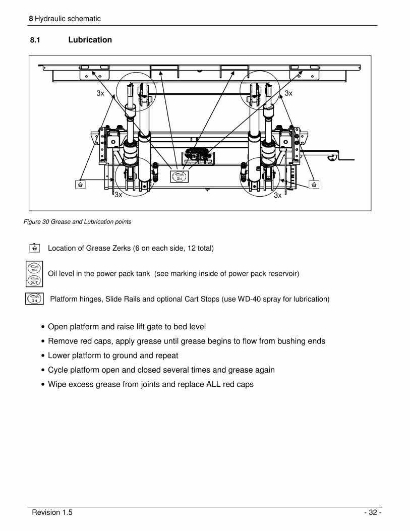
8.1 Lubrication
Location of Grease Zerks (6 on each side, 12 total)
Oil level in the power pack tank (see marking inside of power pack reservoir)
Platform hinges, Slide Rails and optional Cart Stops (use WD-40 spray for lubrication)
• Open platform and raise lift gate to bed level
• Remove red caps, apply grease until grease begins to flow from bushing ends
• Lower platform to ground and repeat
• Cycle platform open and closed several times and grease again
• Wipe excess grease from joints and replace ALL red caps
Figure 30 Grease and Lubrication points
3x 3x
3x 3x
Revision 1.5 - 33 -
Decal Placement 9
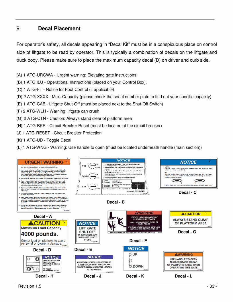
For operator’s safety, all decals appearing in “Decal Kit” must be in a conspicuous place on control
side of liftgate to be read by operator. This is typically a combination of decals on the liftgate and
truck body. Please make sure to place the maximum capacity decal (D) on driver and curb side.
(A) 1 ATG-URGWA - Urgent warning: Elevating gate instructions
(B) 1 ATG ILU - Operational Instructions (placed on your Control Box).
(C) 1 ATG-FT - Notice for Foot Control (if applicable)
(D) 2 ATG-XXXX - Max. Capacity (please check the serial number plate to find out your specific capacity)
(E) 1 ATG-CAB - Liftgate Shut-Off (must be placed next to the Shut-Off Switch)
(F) 2 ATG-WLH - Warning: liftgate can crush
(G) 2 ATG-CTN - Caution: Always stand clear of platform area
(H) 1 ATG-BKR - Circuit Breaker Reset (must be located at the circuit breaker)
(J) 1 ATG-RESET - Circuit Breaker Protection
(K) 1 ATG-UD - Toggle Decal
(L) 1 ATG-WNG - Warning: Use handle to open (must be located underneath handle (main section))
Decal - A
Decal - C
Decal - D
Decal - H
Decal - B
Decal - F
Decal - G
Decal - J
Decal - E
Decal - K Decal - L
Revision 1.5 - 34 -
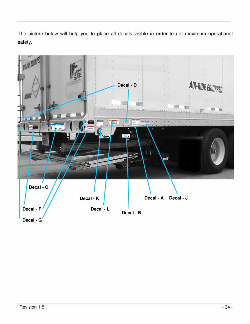
The picture below will help you to place all decals visible in order to get maximum operational
safety.
Decal - A
Decal - C
Decal - D
Decal - B Decal - F
Decal - G
Decal - J Decal - K
Decal - L

Revision 1.5 - 35 -
Check Off Sheet 10
GATE NO. VIN NO.
OWNER'S MANUAL IN CAB
ON-OFF SWITCH WORKING & DECAL IN PLACE
WIRING 1. Power Cord Secured OPERATION 1. All Functions Operate On
2. Cables Not Rubbing Steel Up/Down Control, Hand Control
3. 12V Control Wire Secured 2. Up Stops In Place
4. Loomed & Stapled 3. Platform Meets Body
5. Circuit Breaker & Fuse 4. Wheel Set For Proper
Installed & Decal In Place Opening When Lowering
5. Coil Springs At
HYD. LINES 1. No Rubbing On Frame Platform Adjusted
SECURED 2. No Rubbing On Platform 6. Torsion Rod Installed
3. Up-Down Clear On Platform And Adjusted
4. Storing Platform Clear 7. Snubber Pads Tight4. Snubber Pads Tight Against Platform
HYD. OIL 1. None At Hoses 8. Bolts Removed on On Auto Tilt KnuckleLEAKS 2. None At Power Pack Auto Tilt Knuckles
3. Cylinders
FINAL 1. Platform Touches Ground
WELDS 1. Full Welds Mount Plates INSPECTION 2. Lights Working On Chassis
2. Ground Off / Clean 3. Lic. Plate Bolts & Light
4. Dock Bumper Welded 4. Decals Installed
5. Frame Capped Off 5. Rubber & Plastic Caps
In Place
6. Gate Painted Completely
PUMP 1. Check Fluid With Platform On Ground 7. Body Clean Around Gate
& MOTOR 2. Connections Tight With Heat Shrink 8. Pins Greased - 18 ea.
3. Power Cable Tight 9. Cylinders Clean
4. Ground Cable Tight
5. Breather Installed OPTIONS 1. All Options On Gate
6. Cables Tied Off 2. Cart Stops Working
7. Fuses Tight
PINS 1. Grease Zerks In Place
2. Red Grease Caps On Zerks CHECKED BY
3. Bolts Tight On Pins
DATE
Note:
This must be filled out and kept for your records . A copy of this sheet must be presented
to PALFINGER Liftgates for warranty reimbursement