Illustrated Parts & Packing List - Gandy · Page 1 of 27 Illustrated Parts & Packing List 528...
27
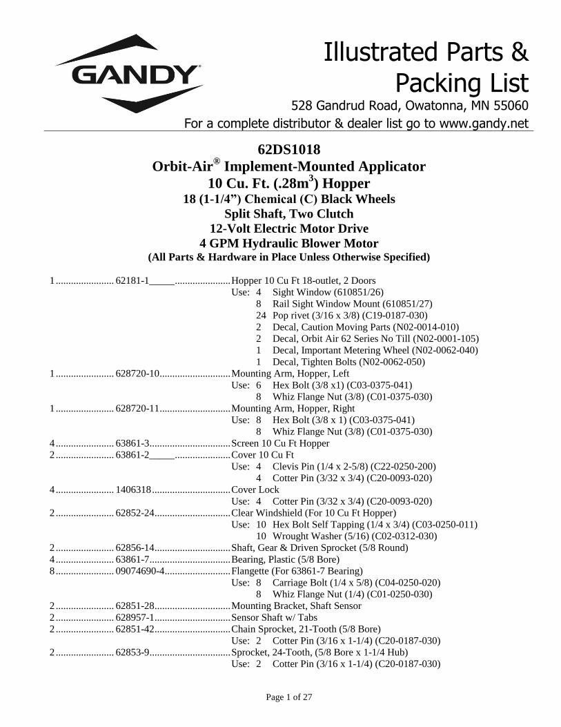
Page 1 of 27 Illustrated Parts & Packing List 528 Gandrud Road, Owatonna, MN 55060 For a complete distributor & dealer list go to www.gandy.net 62DS1018 Orbit-Air ® Implement-Mounted Applicator 10 Cu. Ft. (.28m 3 ) Hopper 18 (1-1/4”) Chemical (C) Black Wheels Split Shaft, Two Clutch 12-Volt Electric Motor Drive 4 GPM Hydraulic Blower Motor (All Parts & Hardware in Place Unless Otherwise Specified) 1 ....................... 62181-1_____...................... Hopper 10 Cu Ft 18-outlet, 2 Doors Use: 4 Sight Window (610851/26) 8 Rail Sight Window Mount (610851/27) 24 Pop rivet (3/16 x 3/8) (C19-0187-030) 2 Decal, Caution Moving Parts (N02-0014-010) 2 Decal, Orbit Air 62 Series No Till (N02-0001-105) 1 Decal, Important Metering Wheel (N02-0062-040) 1 Decal, Tighten Bolts (N02-0062-050) 1 ....................... 628720-10............................ Mounting Arm, Hopper, Left Use: 6 Hex Bolt (3/8 x1) (C03-0375-041) 8 Whiz Flange Nut (3/8) (C01-0375-030) 1 ....................... 628720-11............................ Mounting Arm, Hopper, Right Use: 8 Hex Bolt (3/8 x 1) (C03-0375-041) 8 Whiz Flange Nut (3/8) (C01-0375-030) 4 ....................... 63861-3................................ Screen 10 Cu Ft Hopper 2 ....................... 63861-2_____...................... Cover 10 Cu Ft Use: 4 Clevis Pin (1/4 x 2-5/8) (C22-0250-200) 4 Cotter Pin (3/32 x 3/4) (C20-0093-020) 4 ....................... 1406318 ............................... Cover Lock Use: 4 Cotter Pin (3/32 x 3/4) (C20-0093-020) 2 ....................... 62852-24.............................. Clear Windshield (For 10 Cu Ft Hopper) Use: 10 Hex Bolt Self Tapping (1/4 x 3/4) (C03-0250-011) 10 Wrought Washer (5/16) (C02-0312-030) 2 ....................... 62856-14.............................. Shaft, Gear & Driven Sprocket (5/8 Round) 4 ....................... 63861-7................................ Bearing, Plastic (5/8 Bore) 8 ....................... 09074690-4.......................... Flangette (For 63861-7 Bearing) Use: 8 Carriage Bolt (1/4 x 5/8) (C04-0250-020) 8 Whiz Flange Nut (1/4) (C01-0250-030) 2 ....................... 62851-28.............................. Mounting Bracket, Shaft Sensor 2 ....................... 628957-1.............................. Sensor Shaft w/ Tabs 2 ....................... 62851-42.............................. Chain Sprocket, 21-Tooth (5/8 Bore) Use: 2 Cotter Pin (3/16 x 1-1/4) (C20-0187-030) 2 ....................... 62853-9................................ Sprocket, 24-Tooth, (5/8 Bore x 1-1/4 Hub) Use: 2 Cotter Pin (3/16 x 1-1/4) (C20-0187-030)
Transcript of Illustrated Parts & Packing List - Gandy · Page 1 of 27 Illustrated Parts & Packing List 528...
Page 1 of 27
Illustrated Parts & Packing List
528 Gandrud Road, Owatonna, MN 55060
For a complete distributor & dealer list go to www.gandy.net
62DS1018
Orbit-Air® Implement-Mounted Applicator
10 Cu. Ft. (.28m3) Hopper
18 (1-1/4”) Chemical (C) Black Wheels
Split Shaft, Two Clutch
12-Volt Electric Motor Drive
4 GPM Hydraulic Blower Motor (All Parts & Hardware in Place Unless Otherwise Specified)
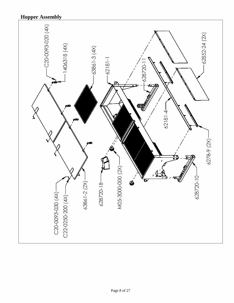
1 ....................... 62181-1_____ ...................... Hopper 10 Cu Ft 18-outlet, 2 Doors
Use: 4 Sight Window (610851/26)
8 Rail Sight Window Mount (610851/27)
24 Pop rivet (3/16 x 3/8) (C19-0187-030)
2 Decal, Caution Moving Parts (N02-0014-010)
2 Decal, Orbit Air 62 Series No Till (N02-0001-105)
1 Decal, Important Metering Wheel (N02-0062-040)
1 Decal, Tighten Bolts (N02-0062-050)
1 ....................... 628720-10 ............................ Mounting Arm, Hopper, Left
Use: 6 Hex Bolt (3/8 x1) (C03-0375-041)
8 Whiz Flange Nut (3/8) (C01-0375-030)
1 ....................... 628720-11 ............................ Mounting Arm, Hopper, Right
Use: 8 Hex Bolt (3/8 x 1) (C03-0375-041)
8 Whiz Flange Nut (3/8) (C01-0375-030)
4 ....................... 63861-3 ................................ Screen 10 Cu Ft Hopper
2 ....................... 63861-2_____ ...................... Cover 10 Cu Ft
Use: 4 Clevis Pin (1/4 x 2-5/8) (C22-0250-200)
4 Cotter Pin (3/32 x 3/4) (C20-0093-020)
4 ....................... 1406318 ............................... Cover Lock
Use: 4 Cotter Pin (3/32 x 3/4) (C20-0093-020)
2 ....................... 62852-24 .............................. Clear Windshield (For 10 Cu Ft Hopper)
Use: 10 Hex Bolt Self Tapping (1/4 x 3/4) (C03-0250-011)
10 Wrought Washer (5/16) (C02-0312-030)
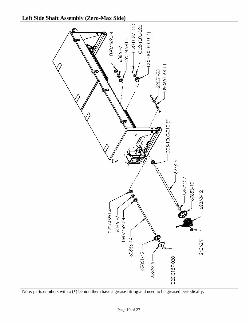
2 ....................... 62856-14 .............................. Shaft, Gear & Driven Sprocket (5/8 Round)
4 ....................... 63861-7 ................................ Bearing, Plastic (5/8 Bore)
8 ....................... 09074690-4 .......................... Flangette (For 63861-7 Bearing)
Use: 8 Carriage Bolt (1/4 x 5/8) (C04-0250-020)
8 Whiz Flange Nut (1/4) (C01-0250-030)
2 ....................... 62851-28 .............................. Mounting Bracket, Shaft Sensor
2 ....................... 628957-1 .............................. Sensor Shaft w/ Tabs
2 ....................... 62851-42 .............................. Chain Sprocket, 21-Tooth (5/8 Bore)
Use: 2 Cotter Pin (3/16 x 1-1/4) (C20-0187-030)
2 ....................... 62853-9 ................................ Sprocket, 24-Tooth, (5/8 Bore x 1-1/4 Hub)
Use: 2 Cotter Pin (3/16 x 1-1/4) (C20-0187-030)

Page 2 of 27
2 ....................... 6278-6 .................................. Shaft (31 x 1-inch Round)
Use: 2 SAE Washer (1-inch) (C02-1000-020)
2 Cotter Pin (3/16 x 1-1/2) (C20-0187-040)
4 ....................... D05-1000-010 ..................... Bearing (1-inch)
Use: 8 Hex Bolt (5/16 x 3/4) (C03-0312-030)
8 Lock Washer (5/16) (C02-0312-010)
8 Hex Nut (5/16) (C01-0312-010)
1 ....................... 62181-5 ................................ Drive Shaft Connector
Use: 2 Cotter Pin (3/16 x 1-1/2) (C20-0187-040)
1 ....................... L05-0010-001 ...................... Electric Clutch
Use: 1 Hex bolt (3/8 x 1-1/2) (C03-0375-061)
2 Whiz Flange Nut (3/8) (C01-0375-030)
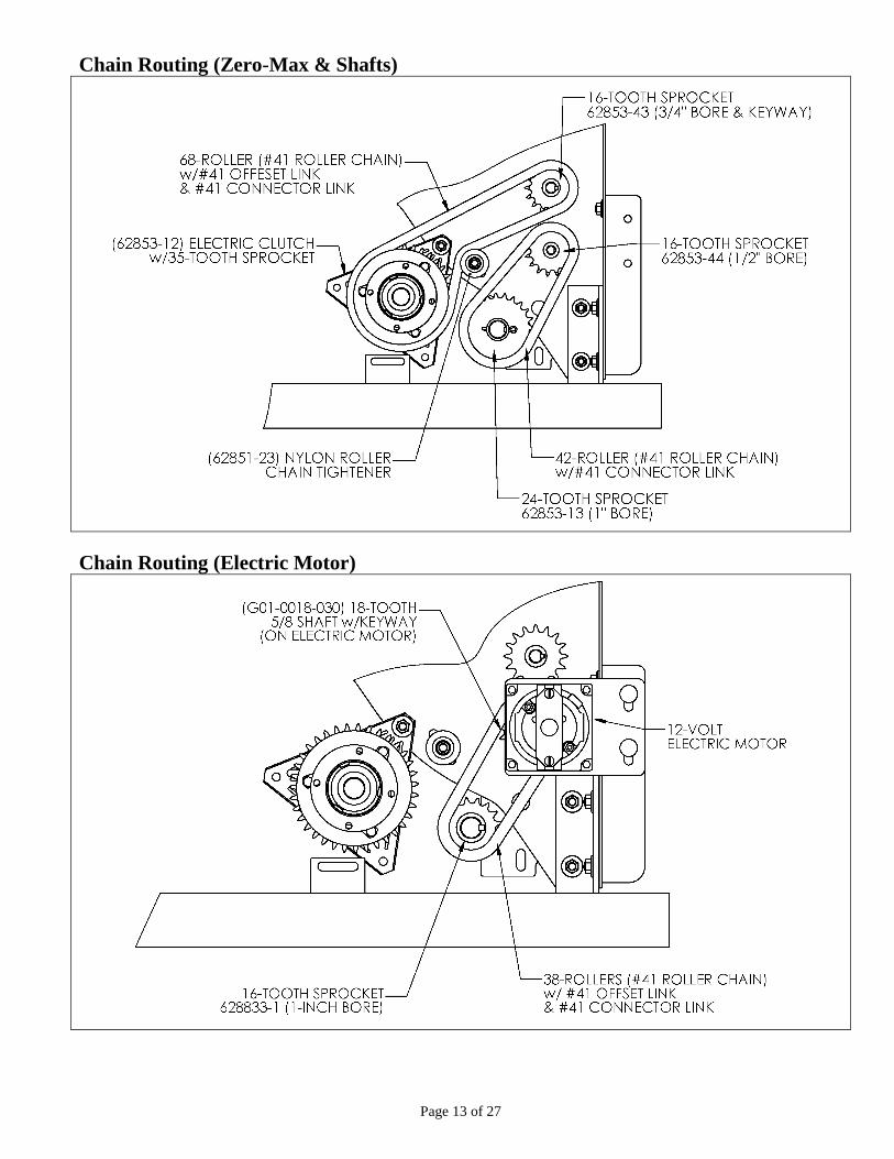
1 ....................... 62853-12 .............................. Electric Clutch w/ 35-Tooth Sprocket (Zero-max Side)
Use: 1 Hex Bolt (3/8 x 1-3/4) (C03-0375-071)
1 Whiz Flange Nut (3/8) (C01-0375-030)
4 Wrought Washer (3/8) (C02-0375-030)
2 ....................... 62853-10 .............................. Chain Sprocket, 32-Tooth (one Bolted to Each Clutch)
Use: 8 Hex Bolt (1/4 x 3/4) (C03-0250-030)
8 Whiz Flange Nut (1/4) (C01-0250-030)
2 ....................... 628720-7 .............................. Bushing (1-1/4 O.D. x 1-1/8 Long) (Clutch Spacer)
2 ....................... 2406251 ............................... Collar Locking (For 1-inch Shaft)
Use: 2 Set Screw (3/8 x 3/8) (C06-0375-030)
3.08 Ft. ............. F02-0041-000 ...................... Roller Chain #41 (68 Rollers) (From Zero Max to Clutch)
Use: 1 Connector Link (#41) (F02-0041-001)
1 Offset Link (#41) (F02-0041-002)
1 ....................... 62851-23 .............................. Nylon Roller (Chain Tightener)
Use: 1 Carriage Bolt (3/8 x 2-1/2) (C04-0375-100)
1 SAE Washer (7/16) (C02-0437-020)
2 Wrought Washer (3/8) (C02-0375-030)
1 Lock Washer (3/8) (C02-0375-010)
1 Hex Nut (3/8) (C01-0375-010)
1 Bushing (9/16 o.d. x 1-5/8 Long) (09065168-11)
1 ....................... 62853-43 .............................. Sprocket, 16-Tooth (5/8 Bore, 1-3/4 Hub)
Use: 2 Socket Set Screw (#10-24 x 5/16) (C06-0187-030)
1 ....................... 62853-44 .............................. Sprocket, 16-Tooth (1/2 Bore x 1-3/8 Hub)
Use: 1 Socket Set Screw (1/4 x 1/4) (C06-0250-020)
1 ....................... G06-0060-001 ..................... Speed Control (Y42 Zero Max)
Use: 4 Carriage Bolt (3/8 x 1) (C04-0375-040)
4 Lock Washer (3/8) (C02-0375-010)
4 Hex Nut (3/8) (C01-0375-010)
1 ....................... 62853-15 .............................. Housing Drive Shaft
Use: 1 Grease Fitting (D01-5010-050)
2 Hex Bolt (3/8 x 1-1/4) (C03-0375-051)
1 Carriage Bolt (3/8 x 1) (C04-0375-040)
2 Wrought Washer (3/8) (C02-0375-030)
3 Whiz Flange Nut (3/8) (C01-0375-030)
1 ....................... 629068-1 .............................. Shaft (7-1/2 x 1-inch Dia.)
Use: 2 SAE Washer (1-inch) (C02-1000-020)
1 Cotter Pin (3/16 x 1-1/2) (C20-0187-040)
1 ....................... 62853-13 .............................. Sprocket 24-Tooth (1-inch Bore x 1-1/2 Hub)
Use: 1 Cotter Pin (3/16 x 1-1/2) (C20-0187-040)
2.04 Ft. ............. F02-0041-000 ...................... Roller Chain #41 (42 Rollers) (24-T Spkt to Zero Max)
Use: 1 Connector Link #41 (F02-0041-001)

Page 3 of 27
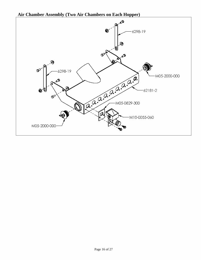
2 ....................... 62181-2 ................................ Air Chamber, 9-outlet Remote
Use: 12 Hex Bolt (3/8 x 3/4) (C03-0375-030)
12 Whiz Flange Nut (3/8) (C01-0375-030)
4 Strap Air Chamber Support (6298-19)
4 ....................... M05-2000-000 ..................... Rubber Plug (2-inch) (for Air Chamber Clean Outs)
18 ..................... M05-0829-300 ..................... Gasket, Mixing Chamber
18 ..................... M10-0055-060 ..................... Mixing Chamber (For 1-1/4 I.D. Tubing)
Use: 36 Hex Head TC Screw (5/16 x 3/4) (C03-0312-032)
2 ....................... M05-3000-000 ..................... Rubber Plug (3-inch) (for Hopper Clean Out)
1 ....................... 628720-18 ............................ Clean-Out Chute (4-inch)
Use: 1 Wing Nut (5/16) (C01-0312-020)
1 Wrought Washer (5/16) (C02-0312-030)
1 Decal, Caution Plug (N02-0062-051)
1 ....................... 62181-4 ................................ Angle Clamp, Tubing
2 ....................... 6278-9 .................................. Bar Clamp, Plastic Tubing
Use: 6 Hex Bolt (5/16 x 2-1/2) (C03-0312-101)
6 Lock Nut, Nylon (5/16) (C01-0312-040)
1 ....................... 62181-3 ................................ Mount, Electric Motor
Use: 1 Hex Bolt (3/8 x 3/4) (C03-0375-030)
1 Whiz Flange Nut (3/8) (C01-375-030)
1 ....................... 629068-5 .............................. Mounting Plate (Electric Motor)
Use: 2 Carriage Bolt (3/8 x 1) (C04-0375-040)
2 Whiz Flange Nut (3/8) (C01-0375-030)
1 ....................... L01-0012-007 ...................... Electric Motor, 12-Volt (Stature)
Use: 4 Hex Bolt (1/4 x 3/4) (C03-0250-030)
4 Lock Washer (1/4) (C02-0250-010)
1 ....................... 24223-2 ................................ Guard, Shaft, Electric Motor
Use: 1 Red Cap (11/16 I.D. x 1/2) (J02-0687-074)
2 Slotted Head Screw (#10-32 x 1/2) (C08-0187-072)
2 Lock Washer (3/16) (C02-0187-010)
1 ....................... G01-0018-030 ..................... Sprocket 18-Tooth (5/8 Bore, 3/16 Keyway)
Use: 1 Key (3/16 x 7/8) (24078179-11)
1 ....................... 628833-1 .............................. Sprocket 16-Tooth (1-inch Bore x 1-1/2 Hub)
Use: 2 Socket Set Screw (1/4 x 1/4) (C06-0250-020)
1 Key (1/4 x 1-3/8) (5508336-6)
2.83 Ft .............. F02-0041-000 ...................... Roller Chain #41 (40 Rollers) (From Electric Motor to 16-T Spkt)
Use: 1 Connector Link #41 (F02-0041-001)
1 ....................... 62181-7 ................................ Wire Harness (Clutch/Sensor)
Use: 12 Cable Tie (3/16 x 8) (L04-0001-000)
2 ....................... 5508442-35 .......................... Magnetic Hub (in Place on Hex Shaft of Each Metering Door)
Use: 2 Spring Pin (3/16 x 1) (C23-0187-140)
1 ....................... 62181-6 ................................ Air Pressure Switch (Mounted to Blower)
Use: 1 Air Pressure Switch Square & Mount Plate (62851-86)
2 Pan Head TC Screw (#8 x 1/2) (C07-0164-070)
1 ....................... 5508242-33 .......................... Gasket, Potting Box (for Air Pressure Switch & Cover)
1 ....................... L10-0016-010 ...................... Potting Box (Air Pressure Switch Cover)
Use: 2 Phillips Pan Head TC Screw (#8-32 x 1/2) (C07-0164-070)

Page 4 of 27
1 ....................... 62851-81 .............................. Remote Blower Housing 2-outlet (Bolted to Blower Assembly)
1 ....................... 62167-PKB ......................... Blower Assembly, Horizon Discharge,
4 GPM Hydraulic Motor, w/ Needle Valve 1 ............. B56-08636-1 ........................ Front Housing, Blower (Plastic)
Use: 14 Hex Bolt (1/4 x 3/4) (C03-0250-030)
28 SAE Washer (1/4) (C02-0250-020)
14 Lock Nut, Nylon (1/4) (C01-0250-040)
1 ............. B56-08636-2 ........................ Back Housing, Blower (Plastic)
1 ............. 5608636-4 ............................ Back-Up Plate
Use: 4 Carriage Bolt (3/8 x 1-1/4) (C04-0375-051)
4 Lock Nut, Nylon (3/8) (C01-0375-041)
1 ............. 62167-2 ................................ Mount, Blower (Plastic w/Coupler)
Use: 1 Decal, Warning Rotating (N02-0055-010)
1 Decal, Caution (N02-0062-050)
1 Decal, Important Hyd Motor (N02-0062-043)
4 Hex Bolt (3/8 x 1-1/2) (C03-0375-061)
4 Lock Washer (3/8) (C02-0375-010)
8 Wrought Washer (3/8) (C02-0375-030)
4 Hex Nut (3/8) (C01-0375-010)
1 ............. L01-0034-004 ...................... Fan, Impeller (For Plastic Housing)
Use: 1 Bushing (1-inch JA Bore) (L01-0033-002)
1 ............. 5408320-25 .......................... Key, Fan Shaft (1/4 x 1-inch)
1 ............. 62167-3 ................................ Shaft (6-inch Long)
1 ............. 28122-49 .............................. Key for Coupler (3/16 x 1-inch)
1 ............. K18-M024-000 .................... Coupler (9/16 x 7/8)
Replacement Parts ............... (K18-M024-003 Black Plastic Coupler Sleeve) (5508230-5 1/8 x1 Key)
(K18-M024-004 Coupler for 9/16 Shaft on Hydraulic Motor)
(K18-M024-005 Coupler for 7/8 Shaft on End of Fan Shaft)
1 ............. K01-0045-001 ..................... Hydraulic Motor, 4-GPM
Use: 2 Carriage Bolt (3/8 x 1-1/4) (C04-0375-051)
2 Washer, Motor Side, Stainless (62164-2)
2 Lock Nut, Nylon (3/8) (C01-0375-041)
2 ............. D05-1000-030 ..................... Bearing & Locking Collar (For 1-inch Shaft)
4 ............. D10-1000-011 ..................... Flangette, Round
Use: 6 Carriage Bolt (5/16 x 1) (C04-0312-040)
6 Lock Washer (5/16) (C02-0312-010)
6 Hex Nut (5/16) (C01-0312-010)
1 ............. 5608231-3 ............................ Screen, Blower
Use: 3 Ph Hd Sheet Screw (#10 x 3/4) (C07-0187-090)
1 ............. 5508336-7 ............................ Guard, Blower Shaft
Use: 2 Thumb Screw (5/16 x 3/4) (C09-0312-100)
2 ............. K02-0500-120 ..................... Hydraulic Hose, 1/2 x 120”
2 ............. K02-0500-012 ..................... Hydraulic Hose, 1/2” x 12”
2 ............. K02-0500-014 ..................... Hydraulic Hose, 1/2 x 14” With O-Ring Fitting On One End
1 ............. L04-0005-000 ...................... Cable Tie (5/16 x 15-1/4)
1 ............. N02-0062-043 ..................... Decal, Tag Important (Attached to Hyd Hoses)
1 ............. 62113 ................................... Hydraulic, By-Pass Block Assembly with Check Valve
1 ....... K05-CV10-200 .................... Check Valve
1 ....... 6296-1 .................................. Hydraulic By-Pass Block
1 ............. 6296 ..................................... Hydraulic, By-Pass Block Assembly w/Needle Valve
1 ....... K05-NV10-20D ................... Needle Calve Hydraulic By-Pass
1 ....... 6296-1 .................................. Hydraulic By-Pass Block

Page 5 of 27
1 ....................... 62181-A ............................... Metering Door Assembly, 9-Outlet Left
(Black Chemical (C) Wheels w/ one 1/2 Rate Wheel)
1 ............. 62851-11 .............................. Mounting Plate, (9-Outlets)
Use: 2 J-Bolt (C16-0312-020)
2 Wrought Washer (5/16) (C02-0312-030)
2 Wing Nut (5/16) (C01-0312-020)
3.17 FT. .. M05-0125-050 ..................... Rubber Strip with Adhesive (1/8 x 1/2)
9 ............. M10-0001-100 ..................... Metering Cup (1-1/4)
Use: 20 Whiz Flange Nut (3/16) (C01-0187-030)
9 ............. 62851-76 .............................. Hole Closure, Slotted
Use: 18 Extruded Washer (628720-20)
9 Hex Bolt (5/16 x 1-3/4) (C03-0312-071) (Stainless)
9 Comp. Spring (E00-0420-012)
1 ............. 62851-14 .............................. Hex Shaft, Metering Wheels (24-13/16 x 5/8 Hex)
2 ............. 63861-7 ................................ Plastic Bearing
4 ............. 09074690-4 .......................... Flangette, Bearing
Use: 4 Hex Bolt (1/4 x 1/2) (C03-0250-013) (Stainless)
4 Lock Washer (1/4) (C01-0250-012) (Stainless)
8 ............. 62851-75 .............................. Metering Wheels, Chemical, Black
16 ........... 62851-72 .............................. Wear Plates (Stainless)
2 ............. 62851-52 .............................. Spacer Block 5/16 Aluminum (1/2 Rate)
1 ............. M10-0001-025 ..................... Metering wheel 1/2 Rate Chemical (C) Black
1 ............. 62851-41 .............................. Sprocket, 21-Tooth (5/8 Bore)
Use: 1 Cotter Pin (3/16 x 1-1/4) (C20-0187-030)
1 ....................... 62181-B ............................... Metering Door Assembly, 9-Outlet Right
(Black Chemical (C) Wheels w/ one 1/2 Rate Wheel)
1 ............. 62851-11 .............................. Mounting Plate, (9-Outlets)
Use: 2 J-Bolt (C16-0312-020)
2 Wrought Washer (5/16) (C02-0312-030)
2 Wing Nut (5/16) (C01-0312-020)
3.17 FT. .. M05-0125-050 ..................... Rubber Strip with Adhesive (1/8 x 1/2)
9 ............. M10-0001-100 ..................... Metering Cup (1-1/4)
Use: 20 Whiz Flange Nut (3/16) (C01-0187-030)
9 ............. 62851-76 .............................. Hole Closure, Slotted
Use: 18 Extruded Washer (628720-20)
9 Hex Bolt (5/16 x 1-3/4) (C03-0312-071) (Stainless)
9 Comp. Spring (E00-0420-012)
1 ............. 62851-14 .............................. Hex Shaft, Metering Wheels (24-13/16 x 5/8 Hex)
2 ............. 63861-7 ................................ Plastic Bearing
4 ............. 09074690-4 .......................... Flangette, Bearing
Use: 4 Hex Bolt (1/4 x 1/2) (C03-0250-013) (Stainless)
4 Lock Washer (1/4) (C01-0250-012) (Stainless)
8 ............. 62851-75 .............................. Metering Wheels, Chemical, Black
16 ........... 62851-72 .............................. Wear Plates (Stainless)
2 ............. 62851-52 .............................. Spacer Block 5/16 Aluminum (1/2 Rate)
1 ............. M10-0001-025 ..................... Metering wheel 1/2 Rate Chemical (C) Black
1 ............. 62851-41 .............................. Sprocket, 21-Tooth (5/8 Bore)
Use: 1 Cotter Pin (3/16 x 1-1/4) (C20-0187-030)
Page 6 of 27
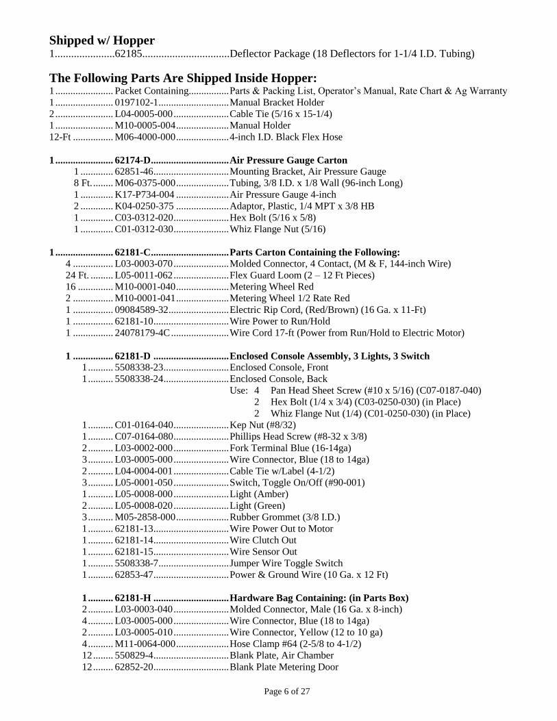
Shipped w/ Hopper 1......................62185................................Deflector Package (18 Deflectors for 1-1/4 I.D. Tubing)
The Following Parts Are Shipped Inside Hopper: 1 ....................... Packet Containing................ Parts & Packing List, Operator’s Manual, Rate Chart & Ag Warranty
1 ....................... 0197102-1 ............................ Manual Bracket Holder
2 ....................... L04-0005-000 ...................... Cable Tie (5/16 x 15-1/4)
1 ....................... M10-0005-004 ..................... Manual Holder
12-Ft ................ M06-4000-000 ..................... 4-inch I.D. Black Flex Hose
1 ....................... 62174-D ............................... Air Pressure Gauge Carton
1 ............. 62851-46 .............................. Mounting Bracket, Air Pressure Gauge
8 Ft. ........ M06-0375-000 ..................... Tubing, 3/8 I.D. x 1/8 Wall (96-inch Long)
1 ............. K17-P734-004 ..................... Air Pressure Gauge 4-inch
2 ............. K04-0250-375 ..................... Adaptor, Plastic, 1/4 MPT x 3/8 HB
1 ............. C03-0312-020 ...................... Hex Bolt (5/16 x 5/8)
1 ............. C01-0312-030 ...................... Whiz Flange Nut (5/16)
1 ....................... 62181-C ............................... Parts Carton Containing the Following:
4 ................ L03-0003-070 ...................... Molded Connector, 4 Contact, (M & F, 144-inch Wire)
24 Ft. ......... L05-0011-062 ...................... Flex Guard Loom (2 – 12 Ft Pieces)
16 .............. M10-0001-040 ..................... Metering Wheel Red
2 ................ M10-0001-041 ..................... Metering Wheel 1/2 Rate Red
1 ................ 09084589-32 ........................ Electric Rip Cord, (Red/Brown) (16 Ga. x 11-Ft)
1 ................ 62181-10 .............................. Wire Power to Run/Hold
1 ................ 24078179-4C ....................... Wire Cord 17-ft (Power from Run/Hold to Electric Motor)
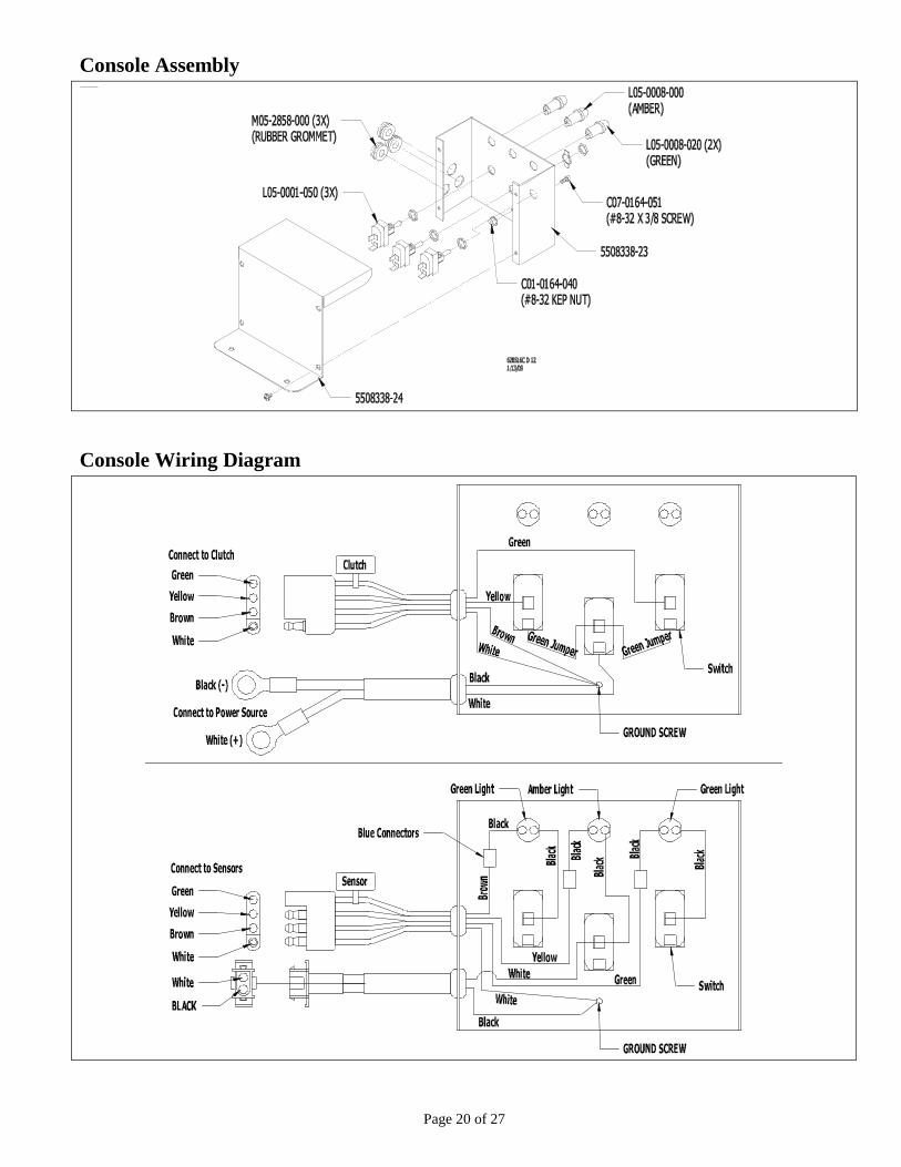
1 ................ 62181-D .............................. Enclosed Console Assembly, 3 Lights, 3 Switch
1 .......... 5508338-23 .......................... Enclosed Console, Front
1 .......... 5508338-24 .......................... Enclosed Console, Back
Use: 4 Pan Head Sheet Screw (#10 x 5/16) (C07-0187-040)
2 Hex Bolt (1/4 x 3/4) (C03-0250-030) (in Place)
2 Whiz Flange Nut (1/4) (C01-0250-030) (in Place)
1 .......... C01-0164-040 ...................... Kep Nut (#8/32)
1 .......... C07-0164-080 ...................... Phillips Head Screw (#8-32 x 3/8)
2 .......... L03-0002-000 ...................... Fork Terminal Blue (16-14ga)
3 .......... L03-0005-000 ...................... Wire Connector, Blue (18 to 14ga)
2 .......... L04-0004-001 ...................... Cable Tie w/Label (4-1/2)
3 .......... L05-0001-050 ...................... Switch, Toggle On/Off (#90-001)
1 .......... L05-0008-000 ...................... Light (Amber)
2 .......... L05-0008-020 ...................... Light (Green)
3 .......... M05-2858-000 ..................... Rubber Grommet (3/8 I.D.)
1 .......... 62181-13 .............................. Wire Power Out to Motor
1 .......... 62181-14 .............................. Wire Clutch Out
1 .......... 62181-15 .............................. Wire Sensor Out
1 .......... 5508338-7 ............................ Jumper Wire Toggle Switch
1 .......... 62853-47 .............................. Power & Ground Wire (10 Ga. x 12 Ft)
1 .......... 62181-H .............................. Hardware Bag Containing: (in Parts Box) 2 .......... L03-0003-040 ...................... Molded Connector, Male (16 Ga. x 8-inch)
4 .......... L03-0005-000 ...................... Wire Connector, Blue (18 to 14ga)
2 .......... L03-0005-010 ...................... Wire Connector, Yellow (12 to 10 ga)
4 .......... M11-0064-000 ..................... Hose Clamp #64 (2-5/8 to 4-1/2)
12 ........ 550829-4 .............................. Blank Plate, Air Chamber
12 ........ 62852-20 .............................. Blank Plate Metering Door

Page 7 of 27
Continued on next page…
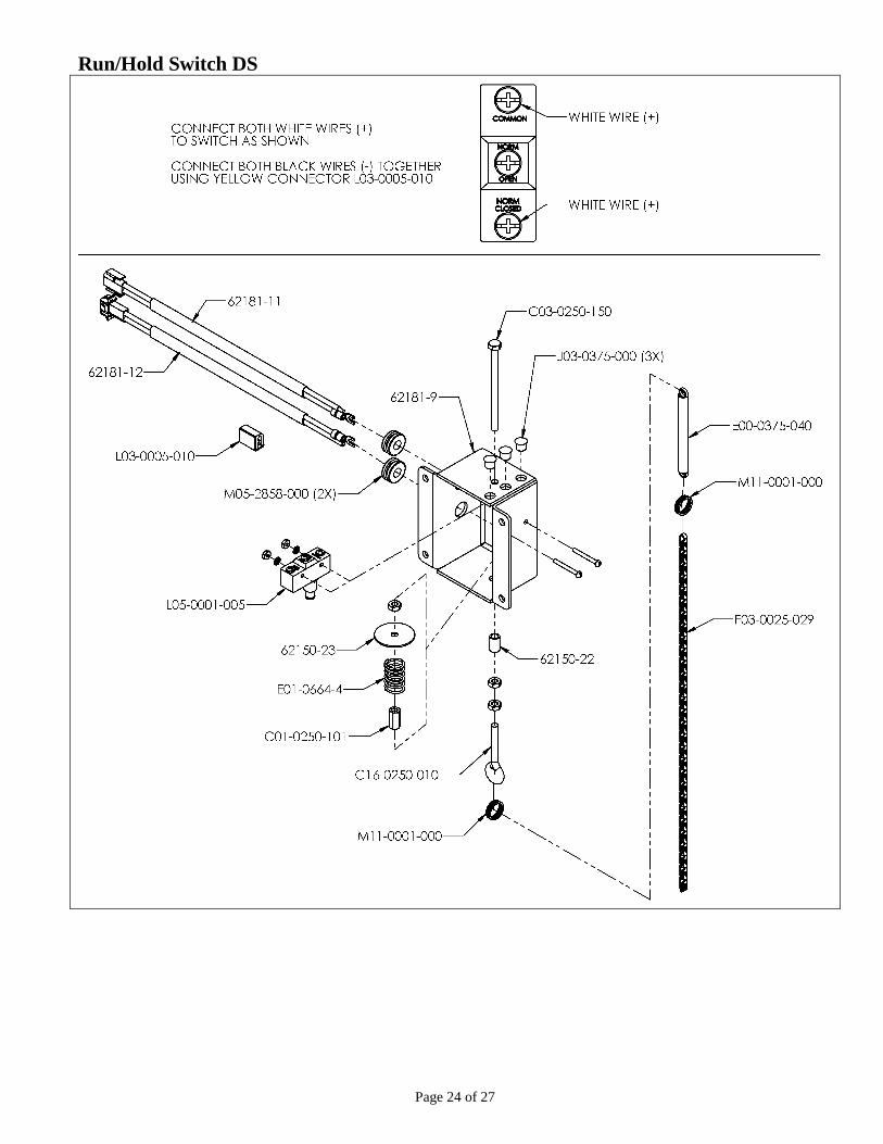
1 ............. 62181-E ............................... Run / Hold Switch DS
1 .......... 62181-9 ................................ Run/Hold Bracket
Use: 3 Hole Plug (3/8) (J03-0375-000)
3 Rubber Grommet (3/8) (M05-2858-000)
1 ........ L05-0001-005 ...................... Switch, Snap Action
Use: 2 Slot Rd Hd Mach Screw (#6-32 x 1-1/4) (C08-0138-140)
2 Shake Proof Washer (#6-32) (C02-0138-040)
2 Hex Nut (#6-32) (C01-0138-010)
1 ........ 62181-11 .............................. Wire Run/Hold Power In
1 ........ 62181-12 .............................. Wire Run/Hold Power Out
1 ........ L03-0005-010 ...................... Wire Connector, Yellow (12 to 10 ga)
1 ........ C16-0250-010 ...................... Eye Bolt (1/4 x 9/16 I.D. x 2-1/2)
Use: 1 Bushing (62150-22)
1 Stop Washer (62150-23)
3 Hex Nut (1/4) (C01-0250-010)
1 Coupling Nut (1/4) (C01-0250-101)
1 Hex Bolt (1/4 x 3-3/4) (C03-0250-150)
1 Compression Spring (E01-0666-4)
1 Sash Chain #25 (29 Links) (F03-0025-029)
2 Key Ring (5/8) (M11-0001-000)
1 Spring 3/8 x 4-inch (E00-0375-040)
Page 8 of 27
Hopper Assembly

Page 9 of 27
Zero-Max Side
Note: parts numbers with a (*) behind them have a grease fitting and need to be greased periodically.
Page 10 of 27
Left Side Shaft Assembly (Zero-Max Side)
Note: parts numbers with a (*) behind them have a grease fitting and need to be greased periodically.

Page 11 of 27
Right Side Shaft Assembly
Note: parts numbers with a (*) behind them have a grease fitting and need to be greased periodically.

Page 12 of 27
Electric Motor
Page 13 of 27
Chain Routing (Zero-Max & Shafts)
Chain Routing (Electric Motor)

Page 14 of 27
Metering Door 62181-A Assembly
Metering Door 62181-B Assembly

Page 15 of 27
Shaft Sensor
Page 16 of 27
Air Chamber Assembly (Two Air Chambers on Each Hopper)

Page 17 of 27
Blower to Remote Housing

Page 18 of 27
Hydraulic Blower Assembly

Page 19 of 27
Hydraulic Hose Connections (2 Port) 4 GPM Motor (K01-0045-001)
Note#1
This block needs to be left in place at all times. This block allows the blower to spin freely and cost out when the hydraulic
supply is shut-off, and also keeps from damaging the hydraulic motor and fan.
Note #2
This block is used to adjust the hydraulic flow to adjust the air pressure if you cannot adjust it from the parent implement. If
hydraulic flow can be adjusted from the parent source then this block can be removed or screwed shout to keep hydraulic fluid
from by-passing and generating extra hydraulic heat.
Page 20 of 27
Console Assembly
Console Wiring Diagram

Page 21 of 27
Wiring Schematics

Page 22 of 27
Wiring Connections: Mount Console in convenient location in tractor cab and connect wires as shown.

Page 23 of 27
Wiring Instructions: (See diagram on page 22.)
1) After mounting hopper and remote blower in desired locations mount console in a convergent location for
operator.
2) Locate wire components from parts carton and hardware bag.
3) Connect the ring terminals to a 12-volt power source. White Wire (+) Black Wire (-)
4) Connect the two 12 foot wire harness (L03-0003-010) to connectors on console and rout to connectors located on
hopper. Install one piece of black flex guard to each wire harness.
5) Locate the two red/brown 8” long molded connectors (L03-0003-040) and connect one to the hopper and one to
the air pressure switch on the remote blower. Locate the red/brown coiled wire (09084589-3) and route from the
air pressure switch to the hopper. Shorten wire to desired length and connect to the two molded connectors using
four blue connectors. Connect red to red and brown to brown.
6) Mounting the Run/Hold Switch. The Run/Hold switch is wired from the factory to be nominally open. The chain
has to be pulled to release the switch to start electric motor. Note: The Run/Hold switch only turn on or off the
electric motor. Fi stopping for long periods of time shut-off the center master switch to cut all power to motor
and clutches. Mount run/Hold switch box to parent implement so switch is sanitary. Connect chain to part of
implement that is being lowered/raised. Note: Chain may have to be lengthened to meet desired length needed.
Make sure if this part of the implement can float that there is enough tension on spring so Run/Hold switch is not
starting and stopping the electric motor when traveling.
7) Connect wire (62181-10) from console to run hold switch. Connect wire (240781798-4C1) to Run/Hold switch
and route to electric motor on hopper. Connect white (+) wire to black (+) wire on motor using yellow connector.
Connect black (-) wire to red (-) wire on motor using the yellow connector.
8) If run/Hold switch is not needed connect wires 62181-10 and 24078179-4C1 together and manual turn on and off
form console.
Page 24 of 27
Run/Hold Switch DS

Page 25 of 27
Blower Mounting: Mount blower in a convenient location, as close to the hopper as possible.
Cut the 4-inch diameter tubing to desired lengths. Connect tubing to remote blower and air manifolds under hopper
using the 4-inch hose clamps provided. See wiring schematic to connect air pressure switch.
Page 26 of 27
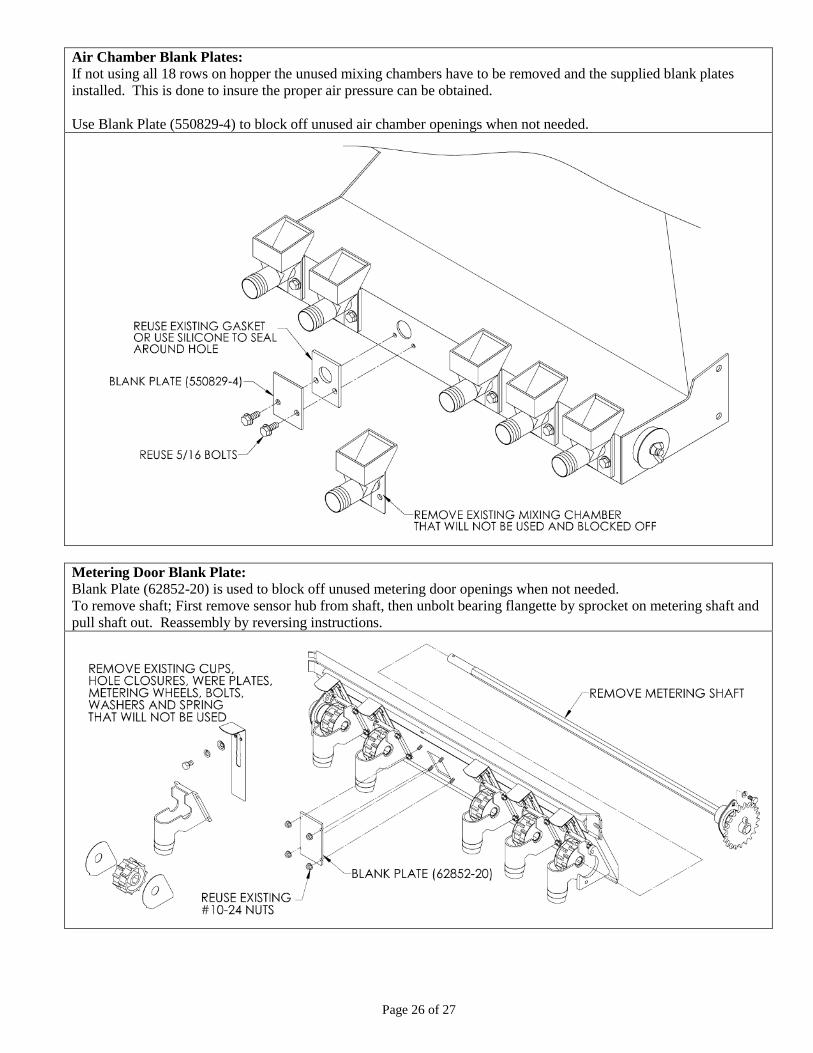
Air Chamber Blank Plates:
If not using all 18 rows on hopper the unused mixing chambers have to be removed and the supplied blank plates
installed. This is done to insure the proper air pressure can be obtained.
Use Blank Plate (550829-4) to block off unused air chamber openings when not needed.
Metering Door Blank Plate:
Blank Plate (62852-20) is used to block off unused metering door openings when not needed.
To remove shaft; First remove sensor hub from shaft, then unbolt bearing flangette by sprocket on metering shaft and
pull shaft out. Reassembly by reversing instructions.

Page 27 of 27
Manual Holder Bracket Mount manual holder to corner of hopper or convergent location on implement.
Store Operator’s manual, Packing List & Rate Chart of convergent access.
Maintenance
Check all bolts for tightness after first two hours of use; check periodically thereafter.
Grease all fittings regularly.
There are five grease fittings on this hopper. These must be greased before use and periodically during use.
Locations: See page 9, 10 & 11.
One grease fitting on each 1-inch bearing (D05-1000-010) (four) located on the 1-inch drive shafts (6278-6).
One grease fitting on drive shaft housing (62853-15) located under Speed control (G06-0060-001).
Lubricate chains as needed.
Periodically clean intake screen on hydraulic driven blower if needed.
See rate-chart for information on mounting deflectors (spacing & height).
February 22, 2013
Printed in the USA