Illumination Distribution from Brightness in Shadows ...Illumination Distribution from Brightness in...
8
Illumination Distribution from Brightness in Shadows: Adaptive Estimation of Illumination Distribution with Unknown Reflectance Properties in Shadow Regions Imari Sato, Yoichi Sato, and Katsushi Ikeuchi Institute of Industrial Science, University of Tokyo 7-22-1 Roppongi, Minato-ku, Tokyo 106-8558, Japan {imarik, ysato, ki}@iis.u-tokyo.ac.jp Abstract This paper describes a new method for estimating the illumination distribution of a real scene from a radiance distribution inside shadows cast by an object in the scene. First, the illumination distribution of the scene is approx- imated by discrete sampling of an extended light source. Then the illumination distribution of the scene is estimated from a radiance distribution inside shadows cast by an ob- ject of known shape onto another object in the scene. In- stead of assuming any particular reflectance properties of the surface inside the shadows, both the illumination dis- tribution of the scene and the reflectance properties of the surface are estimated simultaneously, based on iterative op- timization framework. In addition, this paper introduces an adaptive sampling of the illumination distribution of a scene. Rather than using a uniform discretization of the overall illumination distribution, we adaptively increase sampling directions of the illumination distribution based on the estimation at the previous iteration. Using the adap- tive sampling framework, we are able to estimate overall illumination more efficiently by using fewer sampling direc- tions. The proposed method is effective for estimating an illumination distribution even under a complex illumination environment. 1 Introduction Image brightness is a function of shape, reflectance, and illumination [4]. The relationship among them has pro- vided three major research areas in physics-based vision: shape-from-brightness (with a known reflectance and illu- mination) [6, 7, 8, 16], reflectance-from-brightness (with a known shape and illumination) [9, 1, 11, 12, 15, 17], and illumination-from-brightness (with a known shape and re- flectance). In the past, shape-from-brightness and reflectance-from- brightness have been extensively explored. In contrast, rel- atively limited amounts of research have been conducted in the third area, illumination-from-brightness [3, 14]. Some researchers attacked this problem as a related analysis of shape-from-shading. For example, Brooks and Horn de- termine shape as well as light sources from image bright- ness [7]. However, their analyses are conducted under very specific illumination conditions as in, for example, the case where there is only one direct light source in the scene; the analyses cannot be extended for more natural illumination conditions that include many types of direct and indirect il- lumination. Recently, we proposed a method to recover an illumi- nation distribution of a scene from image brightness with known shape and reflectance of an real object [19]. The method modeled illumination distribution of the scene with discrete sampling of the illumination radiance distribution, then formulated them as a simultaneous linear equation of unknown point sources. Then their brightness was deter- mined by solving them from observed radiance changes in- side shadows cast by an object of known shape onto an- other object surface of known shape and reflectance. 1 This method was effective and could estimate an illumination distribution even under a complex illumination environment such as an ordinary office, including reflections from the wall and other objects in the scene. This method, however, has two limitations. First, it as- sumes that the reflectance properties of the surface inside shadows are given a priori. Otherwise, the method is appli- cable only if the surface is a Lambertian surface. Second, since the method uses a uniform discretization of the over- all illumination for the estimation, the number of sampling 1 In the past, shadows have been used for determining the 3D shapes and orientations of an object which cast shadows onto the scene [2, 10, 13, 20], while very few studies have focused on the the illumination information which shadows could provide. 0-7695-0164-8/99 $10.00 (c) 1999 IEEE
Transcript of Illumination Distribution from Brightness in Shadows ...Illumination Distribution from Brightness in...

Illumination Distribution from Brightness in Shadows:Adaptive Estimation of Illumination Distribution withUnknown Reflectance Properties in Shadow Regions
Imari Sato, Yoichi Sato, and Katsushi IkeuchiInstitute of Industrial Science, University of Tokyo
7-22-1 Roppongi, Minato-ku, Tokyo 106-8558, Japan{imarik, ysato, ki}@iis.u-tokyo.ac.jp
Abstract
This paper describes a new method for estimating theillumination distribution of a real scene from a radiancedistribution inside shadows cast by an object in the scene.First, the illumination distribution of the scene is approx-imated by discrete sampling of an extended light source.Then the illumination distribution of the scene is estimatedfrom a radiance distribution inside shadows cast by an ob-ject of known shape onto another object in the scene. In-stead of assuming any particular reflectance properties ofthe surface inside the shadows, both the illumination dis-tribution of the scene and the reflectance properties of thesurface are estimated simultaneously, based on iterative op-timization framework. In addition, this paper introducesan adaptive sampling of the illumination distribution of ascene. Rather than using a uniform discretization of theoverall illumination distribution, we adaptively increasesampling directions of the illumination distribution basedon the estimation at the previous iteration. Using the adap-tive sampling framework, we are able to estimate overallillumination more efficiently by using fewer sampling direc-tions. The proposed method is effective for estimating anillumination distribution even under a complex illuminationenvironment.
1 Introduction
Image brightness is a function of shape, reflectance, andillumination [4]. The relationship among them has pro-vided three major research areas in physics-based vision:shape-from-brightness (with a known reflectance and illu-mination) [6, 7, 8, 16], reflectance-from-brightness (with aknown shape and illumination) [9, 1, 11, 12, 15, 17], andillumination-from-brightness (with a known shape and re-flectance).
In the past, shape-from-brightness and reflectance-from-brightness have been extensively explored. In contrast, rel-atively limited amounts of research have been conducted inthe third area, illumination-from-brightness [3, 14]. Someresearchers attacked this problem as a related analysis ofshape-from-shading. For example, Brooks and Horn de-termine shape as well as light sources from image bright-ness [7]. However, their analyses are conducted under veryspecific illumination conditions as in, for example, the casewhere there is only one direct light source in the scene; theanalyses cannot be extended for more natural illuminationconditions that include many types of direct and indirect il-lumination.
Recently, we proposed a method to recover an illumi-nation distribution of a scene from image brightness withknown shape and reflectance of an real object [19]. Themethod modeled illumination distribution of the scene withdiscrete sampling of the illumination radiance distribution,then formulated them as a simultaneous linear equation ofunknown point sources. Then their brightness was deter-mined by solving them from observed radiance changes in-side shadows cast by an object of known shape onto an-other object surface of known shape and reflectance.1 Thismethod was effective and could estimate an illuminationdistribution even under a complex illumination environmentsuch as an ordinary office, including reflections from thewall and other objects in the scene.
This method, however, has two limitations. First, it as-sumes that the reflectance properties of the surface insideshadows are given a priori. Otherwise, the method is appli-cable only if the surface is a Lambertian surface. Second,since the method uses a uniform discretization of the over-all illumination for the estimation, the number of sampling
1In the past, shadows have been used for determining the 3D shapes andorientations of an object which cast shadows onto the scene [2, 10, 13, 20],while very few studies have focused on the the illumination informationwhich shadows could provide.
0-7695-0164-8/99 $10.00 (c) 1999 IEEE

directions of illumination tends to be exceedingly large inorder to accurately approximate the illumination distribu-tion.
This paper presents a method to overcome these limi-tations. The solution consists of two main aspects. First,we combine the illumination analysis with an estimationof the reflectance properties of a surface inside shadows.As a consequence, the proposed method becomes applica-ble to the case where reflectance properties of a surface arenot known. This enlarges the variety of images to whichthe method can be applied. Second, we propose an adap-tive sampling framework for efficient estimation of illumi-nation distribution. Rather than using a uniform discretiza-tion of the overall illumination distribution, we adaptivelyincrease the sampling directions of the illumination distri-bution based on the estimation at the previous iteration. Us-ing this adaptive sampling framework, we can avoid un-necessarily dense sampling of the illumination and estimatethe entire illumination distribution more efficiently with asmaller number of sampling directions of the illuminationdistribution.
Our method estimates the illumination distribution of areal scene by using a single color image of the scene withshadows cast by an object. The rest of the paper refers tothe image with shadows as theshadow image, to the ob-ject which casts shadows onto the scene as theoccludingobject, and to the surface onto which theoccluding objectcasts shadows as theshadow surface. In our experiments,we recovered the camera parameters and the shape of theoccluding objectby using a photo-modeling tool interac-tively.2
The rest of the paper is organized as follows. We firstobtain a formula which relates an illumination distributionof a scene with the image irradiance of theshadow imagein Section 2. In Section 3, we describe the basic steps ofthe proposed method for simultaneously estimating both anillumination distribution of a scene and reflectance proper-ties of theshadow surface. In Section 4, we explain howto estimate an illumination radiance distribution from givenreflectance parameters of theshadow surfaceand the ob-served image irradiance of ashadow image. In Section 5,we describe how to estimate the reflectance parameters oftheshadow surfacefor a current estimation of the radiancedistribution of the scene. In Section 6, we introduce anadaptive sampling framework for efficient approximation ofthe entire illumination. In Section 7, we show experimentalresults of the proposed method applied to real images. InSection 8, we present concluding remarks.
2In our examples shown in Section 7, we used a modeling tool calledthe 3D Builder from 3D Construction Company [22] for modeling theshape of anoccluding objectfrom a shadow image. At the same time,the plane ofz = 0 is defined on theshadow surface.
2 Formula for Relating Illumination Radi-ance with Image Irradiance
In this section, we obtain a formula which relates an illu-mination distribution of a real scene with the image irradi-ance of ashadow image. The formula will later be used asa basis for estimating the illumination distribution of a realscene and reflectance properties of theshadow surface.
2.1 From Illumination Radiance to Scene Irradi-ance
First, we find a relationship between the illumination dis-tribution of a real scene and the irradiance at a surface pointin the scene. To take illumination from all directions into ac-count, let us consider an infinitesimal patch of the extendedlight source, of a sizeδθi in polar angle andδφi in azimuthas shown in Figure 1.
Seen from the center pointA, this patch subtends asolid angleδω = sinθiδθiδφi. Let L0(θi, φi) be theillumination radiance per unit solid angle coming fromthe direction (θi, φi); then the radiance from the patch isL0(θi, φi)sinθiδθiδφi[5], and the total irradiance of thesurface pointA is
E =∫ π
−π
∫ π2
0
L0(θi, φi)cosθisinθidθidφi (1)
Then occlusion of the incoming light by theoccluding ob-ject is considered as
E =∫ π
−π
∫ π2
0
L0(θi, φi)S(θi, φi)cosθisinθidθidφi (2)
whereS(θi, φi) are occlusion coefficients;S(θi, φi) = 0 ifL0(θi, φi) is occluded by the occluding object; OtherwiseS(θi, φi) = 1.
2.2 From Scene Irradiance to Scene Radiance
Some of the incoming light at pointA is reflected towardthe image plane. As a result, pointA becomes a secondarylight source with scene radiance.
The bidirectional reflectance distribution function(BRDF) f(θi, φi; θe, φe) is defined as a ratio of the radi-ance of a surface as viewed from the direction(θe, φe)to the irradiance resulting from illumination from thedirection (θi, φi). Thus, by integrating the product ofthe BRDF and the illumination radiance over the entirehemisphere, the scene radianceRs(θe, φe) viewed from thedirection(θe, φe) is computed as
Rs(θe, φe) =∫ π
−π
∫ π2
0
f(θi, φi; θe, φe)L0(θi, φi)
S(θi, φi)cosθisinθidθidφi (3)
0-7695-0164-8/99 $10.00 (c) 1999 IEEE

(a)
φ
θ
n
A
(b)δφ
n
A
δθi
i
Figure 1. (a) the direction of incident and emit-ted light rays (b) infinitesimal patch of an ex-tended light source
2.3 From Scene Radiance to Image Irradiance
Finally, the illumination radiance of the scene is relatedwith image irradiance on the image plane. Since what weactually observe is not image irradiance on the image plane,but rather a recorded pixel value in ashadow image, it isalso necessary to consider the conversion of the image ir-radiance into a pixel value of a corresponding point in theimage. This conversion includes several factors such as D/Aand A/D conversions in a CCD camera and a frame grabber.
Other studies concluded that image irradiance was pro-portional to scene radiance [5]. In our work, we calibratea linearity of the CCD camera by using a Macbeth colorchart with known reflectivity so that the recorded pixel val-ues also become proportional to the scene radiance of thesurface. From Equation 3 the pixel value of theshadow im-ageP (θe, φe) is thus computed as
P (θe, φe) = k
∫ π
−π
∫ π2
0
f(θi, φi; θe, φe)L0(θi, φi)
S(θi, φi)cosθisinθidθidφi (4)
where k is a scaling factor between scene radiance anda pixel value. Due to the scaling factork, we are ableto estimate unknownL0(θi, φi)(i = 1, 2, .., n) up to scale.To obtain the scale factork, we need to perform photo-metric calibration between pixel intensity and physical unit(watt/m2) for the irradiance.
2.4 Approximation of Illumination Distributionwith Discrete Sampling
In an actual implementation of our method, the illumi-nation distribution is approximated by discrete sampling ofradiance over the entire surface of the extended light source.This can be considered as representing the illumination dis-tribution of the scene by using a collection of imaginary
directional light sources. As a result, the double integral inEquation 4 is approximated as
P (θe, φe) =n∑
i=0
f(θi, φi; θe, φe)L(θi, φi)ωiS(θi, φi)cosθi
(5)wheren is the number of sampling directions,L(θi, φi) isthe illumination radiance per unit solid angle coming fromthe direction(θi, φi), which also includes the scaling factork between scene radiance and a pixel value, andωi is a solidangle for the sampling direction(θi, φi).
For instance, node directions of a geodesic dome canbe used for uniform sampling of the illumination distribu-tion. By usingn nodes of a geodesic dome in a northernhemisphere as a sampling direction, the illumination distri-bution of the scene is approximated as a collection of di-rectional light sources distributed with an equal solid angleω = 2π/n.
In our method, BRDFf(θi, φi; θe, φe) in Equation 5is then parameterized using a simplified Torrance-Sparrowmodel [15, 21]. Using the model, the pixel value of theshadow imageP (θe, φe), is computed as
P (θe, φe) =n∑
i=0
(Kdcosθi + Ks1
cosθre
−γ(θi,φi)2
2σ2 )
S(θi, φi)L(θi, φi)ωi (6)
whereθr is the angle between the surface normal and theviewing direction,γ(θi, φi) is the angle between the surfacenormal and the bisector of the light source direction and theviewing direction,Kd andKs are constants for the diffuseand specular reflection components, andσ is the standarddeviation of a facet slope of the Torrance-Sparrow reflectionmodel.
Note that, since each pixel consists of 3 color bands (R,G, and B), each band of radianceL(θi, φi) is also estimatedfrom the corresponding color band of the image separately.Also, based on the dichromatic reflection model, five pa-rameters (Kd,R, Kd,G, Kd,B, Ks, andσ) are considered asthe reflectance parameters of theshadow surface. Accord-ingly, L(θi, φi) is estimated usingKs, σ, and the corre-sponding color band ofKd. In this paper, we explain ourmethod by usingL(θi, φi),Kd, Ks, andσ for the simplic-ity of our discussion.
3 Basic Steps of the Proposed Method
Based on the formula in Equation 6 which relates the il-lumination radiance of the scene with the pixel values of theshadow image, the illumination radiance distribution of thescene is estimated from image brightness inside shadows asdescribed in the following steps.
0-7695-0164-8/99 $10.00 (c) 1999 IEEE

1. Initialize the reflectance parameters of theshadow sur-face. Typically, we assume theshadow surfaceto beLambertian, and the diffuse parameterKd is set to bethe pixel value of the brightest point on theshadowsurface. The specular parameters are set to be zero(Ks = 0, σ = 0). 3
2. Estimate radiance valuesL(θi, φi) of imaginary di-rectional light sources which model the illuminationdistribution of a real scene. By using the reflectanceparameters (Kd, Ks, σ) and image brightness insideshadows in theshadow image, the radiance distribu-tion L(θi, φi) is computed. (Section 4)
3. Estimate the reflectance parameters of theshadow sur-face(Kd, Ks, σ) from the obtained radiance distribu-tion of the sceneL(θi, φi) by using an optimizationtechnique. (Section 5)
4. Estimate the radiance distribution of the sceneL(θi, φi) from the obtained reflectance parameters(Kd, Ks, σ). (Section 4)
5. Proceed to the next step if there is no significantchange in the estimated valuesL(θi, φi),Kd, Ks, andσ. Otherwise, go back to Step 3. By estimatingboth the radiance distribution of the scene and the re-flectance parameters of theshadow surfaceiteratively,we can obtain the best estimation of those values fora given set of sampling directions of the illuminationradiance distribution of the scene.
6. Terminate the estimation process if the obtained illu-mination radiance distribution approximates the realradiance distribution with sufficient accuracy. Other-wise, proceed to the next step.
7. Increase the sampling directions of the illuminationdistribution adaptively based on the obtained illumina-tion radiance distributionL(θi, φi) (Section 6). Thengo back to Step 2.
We should clarify the assumptions that we made for theproposed method. In our method, it is assumed that lightsources in the scene are sufficiently distant from the objects,and thus all light sources project parallel rays onto the ob-ject surface. Also, the method does not take into accountinterreflection between a shadow region and anoccludingobjectcasting the shadow. We also assume that theshadowsurfacehas uniform reflectance properties over the entiresurface. Although these assumptions are not exactly true
3Note that the initial value ofKd is not so important since there is ascaling factor between the reflectance parameters and illumination radi-ance values in any case. To fix the scaling factor, we need to perform pho-tometric calibration of our imaging system with a calibration target whosereflectance is given a priori.
in real situations, we find through experiments that theseassumptions have little effect on estimated illumination dis-tribution in most cases.
In the following sections, each step of the proposedmethod will be explained in more detail.
4 Estimation of Radiance Distribution basedon Reflectance Parameters of Shadow Sur-face
In this section, we explain how to estimate the radiancedistribution of the sceneL(θi, φi) for a given set of re-flectance parameters (Kd, Ks, σ). In the following sections,we referL(θi, φi) as toLi for simplicity.
Using Equation 6 which relates the illumination radianceof the scene with the pixel values of theshadow image, illu-mination radiance is estimated based on the recorded pixelvalues of theshadow image. From Equation 6, a linearequation is obtained for each image pixel of theshadow im-ageas
a1L1 + a2L2 + a3L3 + · · · + a1nLn = P (7)
whereLi (i = 1, 2, .., n) aren unknown illumination radi-ance specified byn sampling directions of the radiance dis-tribution for the scene. The coefficientsai(i = 1, 2, .., n)
represent(Kdcosθi + Ks1
cosθre
−γ(θi,φi)2
2σ2 )S(θi, φi) (i =
1, 2, .., n); we computeθi, θr, γ(θi, φi), andS(θi, φi) basedon 3D geometry of the surface point corresponding to theimage pixel, the illumination direction, and the shape ofthe occluding object. P is the values of the image pixelP (θe, φe).
If we select a number of pixels, saym pixels, a set oflinear equations is obtained as
a11L1 + a12L2 + a13L3+ · · · + a1nLn = P1
a21L1 + a22L2 + a23L3+ · · · + a2nLn = P2
a31L1 + a32L2 + a33L3+ · · · + a3nLn = P3
· · · · · ·am1L1 + am2L2 + am3L3+ · · · + amnLn = Pm (8)
Therefore, by selecting a sufficiently large number of im-age pixels, we are able to solve for a unique solution set ofunknownLi’s.
In general, the number of image pixels in shadows is farlarger than the number of illumination radiance values tobe estimated. Thus we need to select appropriate imagepixels for better computational efficiency. In our method,image pixels are selected by considering their coefficientsai so that the set of linear equations (Equation 8) becomessufficiently over determined by a smaller number of imagepixels.
0-7695-0164-8/99 $10.00 (c) 1999 IEEE

5 Estimation of Reflectance Parameters ofShadow Surface based on Radiance Distri-bution
In this section, we describe how to estimate the re-flectance parameters of theshadow surface(Kd, Ks, σ) byusing the estimated radiance distribution of the sceneLi.
Unlike the estimation of the radiance distribution of thesceneLi which can be done by solving a set of linear equa-tions (Equation 8), we estimate the reflectance parametersof theshadow surfaceby minimizing a sum of squared dif-ference between the observed pixel intensities in theshadowimageand pixel values for the corresponding surface points.Hence the function to be minimized is defined as
f =m∑
j=0
(Pj′ − Pj)2 (9)
wherePj′ is the observed pixel intensities in shadows cast
by theoccluding object, Pj is the pixel value of the corre-sponding surface points computed by using the given radi-ance distribution of the sceneLi in Equation 6,m is thenumber of pixels used for minimization. In our method,the error function in Equation 9 is minimized with respectto the reflectance parametersKd, Ks, andσ by the Pow-ell method to obtain the best estimation of those reflectanceparameters.
6 Adaptive Sampling of Radiance Distribu-tion
If the estimated radiance distribution for a set of sam-pling directions does not approximate the illumination dis-tribution of the scene with sufficient accuracy, we increasethe sampling directions adaptively based on the current es-timation of the illumination radiance distribution.
Radiance distribution changes very rapidly around a di-rect light source such as a fluorescent light. Therefore,the radiance distribution has to be approximated by usinga large number of samplings so that the rapid change ofradiance distribution around a direct light source is cap-tured. Also, to correctly reproduce soft shadows cast byextended light sources, radiance distribution inside a directlight source has to be sampled densely.
On the other hand, coarse sampling of radiance distri-bution is enough for an indirect light source such as a wallwhose radiance remains small. As a result, the number ofsampling directions required for accurately estimating an il-lumination distribution of a real scene becomes exceedinglylarge.
To overcome this problem, we increase sampling direc-tions adaptively based on the estimation at the previous it-eration, rather than by using a uniform discretization of the
overall illumination distribution. In particular, we increasesampling directions around and within direct light sources.
Based on the estimated radiance distributionLi for thesampling directions at the previous step, additional sam-pling directions are determined as follows.
Suppose three sampling directions with radiance valuesL1, L2, andL3 are placed to form a triangleM1 as illus-trated in Figure 2. To determine whether a new samplingdirection needs to be added betweenL1 andL2 or not, weconsider the following cost function.
U(L1, L2) = diff(L1, L2) + αmin(L1, L2)angle(L1, L2)(10)
wherediff(L1, L2) is the radiance difference betweenL1
andL2, min(L1, L2) gives the smaller radiance ofL1 andL2, angle(L1, L2) is the angle between directions toL1
andL2, andα is a manually specified parameter which de-termines the relative weights of those two factors. The firstterm is required to capture the rapid change of radiance dis-tribution around direct light sources, while the second termleads to fine sampling of the radiance distribution inside di-rect light sources. The additional termangle(L1, L2) isused for avoiding unnecessarily dense sampling inside di-rect light sources. In our experiments,α is set to0.5.
If the costU is large, a new sampling direction is addedbetweenL1 andL2. In our experiments, we computed thecost function valuesU for all pairs of neighboring samplingdirections, then added additional sampling directions for thefirst 50% of all the pairs in order of the cost function valuesU .
L1
L2
L3
L1
L3
L2
Ln+1
M1
Figure 2. Subdivision of sampling directions
7 Experimental Results
We have tested the proposed method by using real im-ages taken in both indoor and outdoor environments.
An image with anoccluding object, i.e., shadow im-age, was taken under usual illumination environment inour office, including direct light sources such as fluorescentlamps, as well as indirect illumination such as reflectionsfrom a ceiling and a wall. The input image is shown in Fig-ure 3 (a).
First, the shape of theoccluding objectand the cameraparameters of the input image were obtained by using a
0-7695-0164-8/99 $10.00 (c) 1999 IEEE
(a) (b)
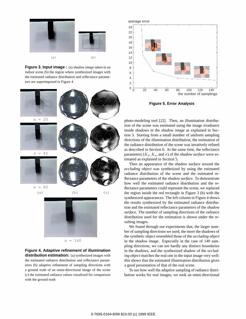
Figure 3. Input image : (a)shadow imagetaken in anindoor scene (b) the region where synthesized images withthe estimated radiance distribution and reflectance parame-ters are superimposed in Figure 4
n = 140
n = 20
n = 40
n = 80
(a) (b) (c)
Figure 4. Adaptive refinement of illuminationdistribution estimation: (a) synthesized images withthe estimated radiance distribution and reflectance param-eters (b) adaptive refinement of sampling directions witha ground truth of an omni-directional image of the scene(c) the estimated radiance values visualized for comparisonwith the ground truth
average error
the number of samplings
0
2
4
6
8
10
12
14
16
18
20
22
24
20 40 60 80 100 120 1400
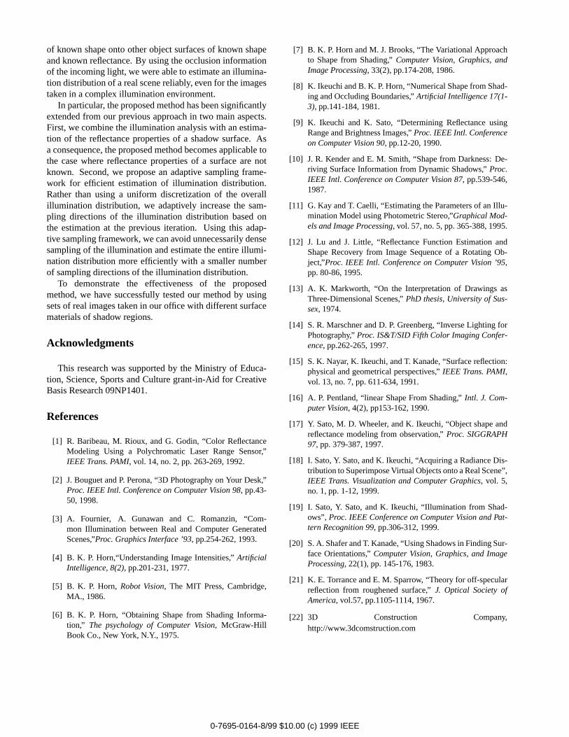
Figure 5. Error Analysis
photo-modeling tool [22]. Then, an illumination distribu-tion of the scene was estimated using the image irradianceinside shadows in theshadow imageas explained in Sec-tion 3. Starting from a small number of uniform samplingdirections of the illumination distribution, the estimation ofthe radiance distribution of the scene was iteratively refinedas described in Section 6. At the same time, the reflectanceparameters (Kd, Ks, andσ) of theshadow surfacewere es-timated as explained in Section 5.
Then an appearance of theshadow surfacearound theoccluding objectwas synthesized by using the estimatedradiance distribution of the scene and the estimated re-flectance parameters of theshadow surface. To demonstratehow well the estimated radiance distribution and the re-flectance parameters could represent the scene, we replacedthe region inside the red rectangle in Figure 3 (b) with thesynthesized appearances. The left column in Figure 4 showsthe results synthesized by the estimated radiance distribu-tion and the estimated reflectance parameters of theshadowsurface. The number of sampling directions of the radiancedistribution used for the estimation is shown under the re-sulting images.
We found through our experiments that, the larger num-ber of sampling directions we used, the more the shadows ofthe synthetic object resembled those of theoccluding objectin the shadow image. Especially in the case of 140 sam-pling directions, we can see hardly any distinct boundariesin the shadows, and the synthesized shadow of theocclud-ing objectmatches the real one in the input image very well:this shows that the estimated illumination distribution givesa good presentation of that of the real scene.
To see how well the adaptive sampling of radiance distri-bution works for real images, we took an omni-directional
0-7695-0164-8/99 $10.00 (c) 1999 IEEE

image of the office scene as a ground truth. The middle col-umn of Figure 4 shows the omni-directional image of thescene taken by placing a camera with a fisheye lens look-ing upward on theshadow surfacein Figure 3 (a). Theomni-directional image shows both direct light sources, i.e.,fluorescent lamps in our office, and indirect light sourcessuch as a ceiling and walls. The right column of Figure 4shows the estimated radiance values visualized for compar-ison with the ground truth. In those images in Figure 4 (b)and (c), we can see that sampling directions of the radi-ance distribution were nicely added only around the directlight sources at each step by the proposed adaptive samplingframework, starting from the coarse sampling directions atthe top row.
Figure 5 numerically shows the improvement of the ac-curacy by adaptive refinement of sampling directions andthe estimation of reflectance properties of theshadow sur-face. The vertical axis represents average error in pixel val-ues inside the synthesized images in the region shown inFigure 3 (b) compared with that in the input image Figure 3(a). Here, the initial average pixel values of shadow regionsin theshadow imageare set to100 %. The horizontal axisrepresents the number of sampling directions used for theestimation. From the plot in the figure, we can clearly seethat the accuracy improves rapidly as we adaptively increasesampling directions of the radiance distribution. Also thesmall pictures at the bottom show error distributions insidethe region. Darker color represents larger error in a pixelvalue in the shadow regions compared with the real shad-ows of theoccluding objectin theshadow image.
To confirm the merit of the adaptive sampling frame-work and the estimation of the reflectance parameters of theshadow surface, we also estimated the illumination radiancedistribution with uniform sampling and fixed reflectance pa-rameters. In that case, even 300 uniformly sampled direc-tions could not achieve the same level of accuracy as theestimation result obtained by 80 sampling directions withthe method proposed in this work.
Figure 6 (a) shows another example image taken outsidethe entrance lobby of our building in the late afternoon. Inthis image, we used the rectangular pole with two colors asanoccluding objectcasting shadows. In the same way as theprevious example, the shape of theoccluding objectand thecamera parameters of the input image were obtained by us-ing a photo-modeling tool. Then, an illumination distribu-tion of the scene was estimated using the image irradianceinside shadows in the input image as explained in Section 3.
Then an appearance of theshadow surfacearound theoccluding object, illustrated with a red rectangle in Figure 7(b), was synthesized by using the estimated radiance distri-bution of the scene and the estimated reflectance parame-ters of theshadow surface[18]. Figure 7 shows the result-
(a) (b)
Figure 6. Input image : (a) shadow imagetaken inan outdoor scene (b) the region where synthesized imageswith the estimated radiance distribution and reflectance pa-rameters are superimposed in Figure 7
n = 20 n = 40
n = 80 n = 140
Figure 7. Adaptive refinement of illuminationdistribution estimation: synthesized images with theestimated radiance distribution and reflectance parameters
ing images by our method. Although the grid pattern ontheshadow surfaceis missing in those synthesized imagesdue to the assumption of uniform reflectance on theshadowimage, the appearance of the shadow around theoccludingobjectsis virtually indistinguishable in the case of 140 sam-pling directions. This shows that the estimated illuminationdistribution gives a good representation of the characteris-tics of the real scene.
8 Conclusions
In this paper, we have proposed a new method for esti-mating an illumination distribution of a real scene from aradiance distribution inside shadows cast by a real object
0-7695-0164-8/99 $10.00 (c) 1999 IEEE
of known shape onto other object surfaces of known shapeand known reflectance. By using the occlusion informationof the incoming light, we were able to estimate an illumina-tion distribution of a real scene reliably, even for the imagestaken in a complex illumination environment.
In particular, the proposed method has been significantlyextended from our previous approach in two main aspects.First, we combine the illumination analysis with an estima-tion of the reflectance properties of a shadow surface. Asa consequence, the proposed method becomes applicable tothe case where reflectance properties of a surface are notknown. Second, we propose an adaptive sampling frame-work for efficient estimation of illumination distribution.Rather than using a uniform discretization of the overallillumination distribution, we adaptively increase the sam-pling directions of the illumination distribution based onthe estimation at the previous iteration. Using this adap-tive sampling framework, we can avoid unnecessarily densesampling of the illumination and estimate the entire illumi-nation distribution more efficiently with a smaller numberof sampling directions of the illumination distribution.
To demonstrate the effectiveness of the proposedmethod, we have successfully tested our method by usingsets of real images taken in our office with different surfacematerials of shadow regions.
Acknowledgments
This research was supported by the Ministry of Educa-tion, Science, Sports and Culture grant-in-Aid for CreativeBasis Research 09NP1401.
References
[1] R. Baribeau, M. Rioux, and G. Godin, “Color ReflectanceModeling Using a Polychromatic Laser Range Sensor,”IEEE Trans. PAMI, vol. 14, no. 2, pp. 263-269, 1992.
[2] J. Bouguet and P. Perona, “3D Photography on Your Desk,”Proc. IEEE Intl. Conference on Computer Vision 98, pp.43-50, 1998.
[3] A. Fournier, A. Gunawan and C. Romanzin, “Com-mon Illumination between Real and Computer GeneratedScenes,”Proc. Graphics Interface ’93, pp.254-262, 1993.
[4] B. K. P. Horn,“Understanding Image Intensities,”ArtificialIntelligence, 8(2), pp.201-231, 1977.
[5] B. K. P. Horn, Robot Vision, The MIT Press, Cambridge,MA., 1986.
[6] B. K. P. Horn, “Obtaining Shape from Shading Informa-tion,” The psychology of Computer Vision, McGraw-HillBook Co., New York, N.Y., 1975.
[7] B. K. P. Horn and M. J. Brooks, “The Variational Approachto Shape from Shading,”Computer Vision, Graphics, andImage Processing, 33(2), pp.174-208, 1986.
[8] K. Ikeuchi and B. K. P. Horn, “Numerical Shape from Shad-ing and Occluding Boundaries,”Artificial Intelligence 17(1-3), pp.141-184, 1981.
[9] K. Ikeuchi and K. Sato, “Determining Reflectance usingRange and Brightness Images,”Proc. IEEE Intl. Conferenceon Computer Vision 90, pp.12-20, 1990.
[10] J. R. Kender and E. M. Smith, “Shape from Darkness: De-riving Surface Information from Dynamic Shadows,”Proc.IEEE Intl. Conference on Computer Vision 87, pp.539-546,1987.
[11] G. Kay and T. Caelli, “Estimating the Parameters of an Illu-mination Model using Photometric Stereo,”Graphical Mod-els and Image Processing, vol. 57, no. 5, pp. 365-388, 1995.
[12] J. Lu and J. Little, “Reflectance Function Estimation andShape Recovery from Image Sequence of a Rotating Ob-ject,”Proc. IEEE Intl. Conference on Computer Vision ’95,pp. 80-86, 1995.
[13] A. K. Markworth, “On the Interpretation of Drawings asThree-Dimensional Scenes,”PhD thesis, University of Sus-sex, 1974.
[14] S. R. Marschner and D. P. Greenberg, “Inverse Lighting forPhotography,”Proc. IS&T/SID Fifth Color Imaging Confer-ence, pp.262-265, 1997.
[15] S. K. Nayar, K. Ikeuchi, and T. Kanade, “Surface reflection:physical and geometrical perspectives,”IEEE Trans. PAMI,vol. 13, no. 7, pp. 611-634, 1991.
[16] A. P. Pentland, “linear Shape From Shading,”Intl. J. Com-puter Vision, 4(2), pp153-162, 1990.
[17] Y. Sato, M. D. Wheeler, and K. Ikeuchi, “Object shape andreflectance modeling from observation,”Proc. SIGGRAPH97, pp. 379-387, 1997.
[18] I. Sato, Y. Sato, and K. Ikeuchi, “Acquiring a Radiance Dis-tribution to Superimpose Virtual Objects onto a Real Scene”,IEEE Trans. Visualization and Computer Graphics, vol. 5,no. 1, pp. 1-12, 1999.
[19] I. Sato, Y. Sato, and K. Ikeuchi, “Illumination from Shad-ows”, Proc. IEEE Conference on Computer Vision and Pat-tern Recognition 99, pp.306-312, 1999.
[20] S. A. Shafer and T. Kanade, “Using Shadows in Finding Sur-face Orientations,”Computer Vision, Graphics, and ImageProcessing, 22(1), pp. 145-176, 1983.
[21] K. E. Torrance and E. M. Sparrow, “Theory for off-specularreflection from roughened surface,”J. Optical Society ofAmerica, vol.57, pp.1105-1114, 1967.
[22] 3D Construction Company,http://www.3dcomstruction.com
0-7695-0164-8/99 $10.00 (c) 1999 IEEE
![Robust Lane Detection in Shadows and Low Illumination ... · shadows. A survey of the recent lane detection mes are prthod e-sented in [9, 10]. There has been progress in detection](https://static.fdocuments.us/doc/165x107/5e6e595ac5ca634bbc4b1bbf/robust-lane-detection-in-shadows-and-low-illumination-shadows-a-survey-of-the.jpg)