I,L! - Sears Parts Direct · Canada), ABS-DWV, or ABS-F628 Schedule ... see Air Delivery table for...
16
Heating & Cooling INSTALLATION FLEXIBILITY: CASING: COMBUSTION SYSTEM: 3-PASS PRIMARY HEAT EXCHANGERS: FLOW-THROUGH SECONDARY HEAT EXCHANGERS: LIMITED WARRANTY: MONOPORT INSHOT _ BURNERS: ® / FEATURES The 4-way multipoise design allows a model PG9MAA to be installed in an upflow, downflow, or horizon- tal orientation. Atl sizes of the PG9MAA may be installed in direct vent (2-pipe) applications. All sizes except the t40 size may be installed in non-direct vent (1-pipe) applications. The 140 size also has an elevation limitation of 7,000 ft. See "Combustion Air and Vent Pipe" table for more information. The casing also has the required openings for left- or right-side connection of gas, electric, drain, and vent connections. INTEGRATED CONTROL CENTER: COMBUSTION Enclosed burner assembly isolates operating noise without the expense of sound deadening devices. This design accelerates heat trans- fer and extracts heat that conven- tiona! heat exchangers waste up the flue. The primary heat ex- changer is made of aluminized steel for corrosion resistance. AIR AND VENTILATION: Each cell is laminated with our pa- tented polypropylene for greater corrosion resistance to help extend the life of the furnace for years of dependable performance. The heat exchanger is positioned in the fur- nace to extract additional heat from the combustion products regard- less of furnace orientation. CERTIFICATIONS: The PG9MAA is backed by a Life- time Warranty on the heat ex- changers in direct vent application (2O-year in non-direct vent applica- tions) and a 5-year Warranty on al! other parts. Produce precise air-to-gas mixture which gives a clean burn. The large monoport on the inshot or injec- QUALITY REGISTRATION: tion-type burners seldom, if ever, needs cleaning. The printed-circuit board has con- venient terminals which permit quick-connection of a thermostat, air conditioning control circuits, a humid- ifier, or an air cleaner. The control has a built-in status indicator and self-test feature. A self-test feature allows for a complete check of the major components in about 60 sec- onds. The control also features an adjustable blower off delay. The PG9MAA advanced design attows Schedute 40 PVC, Schedule 40 CPVC pipe and fit- tings, PVC-DWV, SDR-21 PVC, SDR-26 PVC (not approved in Canada), ABS-DWV, or ABS- F628 Schedule 40 pipe to bring air into the furnace for combus- tion and to be used for venting combustion products outside the structure. The vent pipe can ter- minate through a sidewall or through the roof. The PG9MAA units are CSA (for- medy A.G.A. and C.G.A.) design certified for use with natural and pro- pane gases, as welt as GAMA efficiency rating certified. The fur- nace is factory-shipped for use with natural gas. A CSA (formerly A.G.A. and C.G.A.) listed gas conversion kit is required to convert fumace for use with propane gas. The model PG9MAA meets Catifomia Air Qual- ity Management District emission requirements. The quality systems for this product have been registered by UL to ISO 900I Standards. m O I,L! or) O SS-PG9M-05
Transcript of I,L! - Sears Parts Direct · Canada), ABS-DWV, or ABS-F628 Schedule ... see Air Delivery table for...

Heating & Cooling
INSTALLATIONFLEXIBILITY:
CASING:
COMBUSTION
SYSTEM:
3-PASS
PRIMARYHEAT
EXCHANGERS:
FLOW-THROUGHSECONDARY
HEATEXCHANGERS:
LIMITED
WARRANTY:
MONOPORT
INSHOT
_ BURNERS:
®
/
FEATURES
The 4-way multipoise design allowsa model PG9MAA to be installed
in an upflow, downflow, or horizon-tal orientation. Atl sizes of the
PG9MAA may be installed in directvent (2-pipe) applications. All sizes
except the t40 size may beinstalled in non-direct vent (1-pipe)
applications. The 140 size alsohas an elevation limitation of 7,000ft. See "Combustion Air and Vent
Pipe" table for more information.
The casing also has the required
openings for left- or right-sideconnection of gas, electric, drain,and vent connections.
INTEGRATED
CONTROLCENTER:
COMBUSTION
Enclosed burner assembly isolatesoperating noise without the expense
of sound deadening devices.
This design accelerates heat trans-fer and extracts heat that conven-
tiona! heat exchangers waste upthe flue. The primary heat ex-
changer is made of aluminizedsteel for corrosion resistance.
AIR AND
VENTILATION:
Each cell is laminated with our pa-
tented polypropylene for greatercorrosion resistance to help extend
the life of the furnace for years ofdependable performance. The heat
exchanger is positioned in the fur-nace to extract additional heat from
the combustion products regard-less of furnace orientation.
CERTIFICATIONS:
The PG9MAA is backed by a Life-
time Warranty on the heat ex-
changers in direct vent application(2O-year in non-direct vent applica-
tions) and a 5-year Warranty on al!other parts.
Produce precise air-to-gas mixture
which gives a clean burn. The largemonoport on the inshot or injec-
QUALITYREGISTRATION:
tion-type burners seldom, if ever,needs cleaning.
The printed-circuit board has con-venient terminals which permit
quick-connection of a thermostat, airconditioning control circuits, a humid-
ifier, or an air cleaner. The controlhas a built-in status indicator andself-test feature. A self-test feature
allows for a complete check of the
major components in about 60 sec-onds. The control also features an
adjustable blower off delay.
The PG9MAA advanced designattows Schedute 40 PVC,
Schedule 40 CPVC pipe and fit-tings, PVC-DWV, SDR-21 PVC,
SDR-26 PVC (not approved inCanada), ABS-DWV, or ABS-
F628 Schedule 40 pipe to bringair into the furnace for combus-
tion and to be used for ventingcombustion products outside the
structure. The vent pipe can ter-minate through a sidewall or
through the roof.
The PG9MAA units are CSA (for-
medy A.G.A. and C.G.A.) designcertified for use with natural and pro-
pane gases, as welt as GAMAefficiency rating certified. The fur-
nace is factory-shipped for use withnatural gas. A CSA (formerly A.G.A.
and C.G.A.) listed gas conversion kitis required to convert fumace for use
with propane gas. The modelPG9MAA meets Catifomia Air Qual-
ity Management District emissionrequirements.
The quality systems for this producthave been registered by UL toISO 900I Standards.
m
O
I,L!
or)
O
SS-PG9M-05

IIx3
I
261_® ,
14 _" S}DE}NLET
Ti +i Z_
CONDENSATEDRAIN
TRAPLOCk'ON(OOWNFLOW&HORIZONTALLEFT)
_ iN DJA. i
32' I_-- _IN DIA _ 30 e, T '
ACCI S80'RY H ":9 ,pow,_ Nr[{Y "1 _
! 2
% CON DENS"_ZE 1
DP.AINT,_AP _,OCATION s(ALTERNATE "4JPF OW) _ _
\t l! !_CON " N_AI h
(UPFLOW)
A _ 2 '
_O_ _ / Typ J 19
OUTLET OU _t _ _,
'_t,,_._otY_ _ A_CO,_ ,"HO_I ONIA _<GH "h
l2£ 5' _1_ _- 2IN VENT CONN 39 15'
I 'I
1 la_/Ifl_aw' ! ......... iL ;
FOR HOR}ZONTAL}_ANG_NG
NOTES: Minimum retu_n-ai_ opening at furnace based on metalduct ;f flex duct is used see flex duct manufacturer's
recommendation for equivalent diameters:1 Fol 800 CFM 16-in fob'f_d or 14-112 X 12dn _ectangle2 For 1200 CFM 2Odn to@rid or 14-1/2 X 19-1/2 in rectangle3 FOr 1600 CFM 22-in rom]d or 14-1/2 X 23-1/4 in rectangle4 For aidiow requiFements above 1800 CFM, see Air DeB,_eryTab!e in p_oduct Specification Sheet for specific use of single sideinlets The use of both side inlets a combina£ion of 1 side and
the bottom or the bottom only will ensure adequate re_urn-ai_opemngs for airflow requirements above 1800 CFM at 05" VVC ESR
UNIT SIZE SHIP. WEIGHT(Lb)
024040 165
036040 166
024060 172
036060 174
048060 t74
036080 188
048080 194
060080 206
048100 219
060100 22t
060120 250
060140 250
DIMENSIONS (In.)
A D E
17-1/2 15-7/8 16
17-1/2 15W/8 16
17-I/2 15-7/8 16
17-I/2 15-7/8 16
t7-t/2 t5-7/8 t6
17-1/2 15-7/8 16
17-1/2 15W/8 16
2t 19-3/8 19-t/2
2t 19-3/8 19-t/2
2t t9-3/8 t9-t/2
24-1/2 22-7/8 23
24-1/2 22W/8 23
A02185

CONDENSATE TRAP
E_D FURNACE
OOR
TRAP(INSID_X_
FIELD--DRAINCONN
UPFLOW APPLICATIONS
/-'-- CONDENSATE
/ TRA_uRNADE--.
_r,--? /_ I_j_-_......?l II 4"
261/4 11/2
SIDE VIEW FRONT VIEW
DOWNFLOW AND ALTERNATEEXTERNAL UPFLOW APPLICATIONS
FURNACE
OOR
FIELD --
DRAINCONN
-- FURNACESIDE
-,,--I I-.,*-3/4
END VIEW FRONT VIEW
HORIZONTALAPPLICATIONS
SLOT FOR SCREW ---/HORIZONTAL
APPLICATION(OPTIONAL) ! ¢ OD
/ COLLECTOR BOX TOTRAP RELIEF PORT
INDUCER HOUSING
3/4__ t DRAIN CONNECTIONCOLLECTOR BOX
71/8 DRAIN CONNECTION
SCREW HOLE FORUPFLOW OR DOWN-FLOW APPLICATIONS
_DE/s IE t 7/8= (OPTIONAL): Vz-IN. PVC OR CPVC
(WHEN USED)
FRONT VIEW SIDE VIEWA93026
MEETS DOE RESIDENTIAL CONSERVATION SERVICESPROGRAM STANDARDS.
Before purchasing this appliance, read importantenergy cost and efficiency information availablefrom your retailer. ISO 8001:2000
As an ENERGY STAR®
partner, Payne Heating &Cooling has determined thatthis product meets theENERGY STAR® guidelinesfor energy efficiency.
m3m

SPECIFICATIONS
UN,TS,ZE I 02404°I 036°4°I 0240 0[ 03 0 0[ 048080[ 03 080RATINGS AND PERFORMANCE
Input Btuh* 40,000 40,000 60,000 60,000 60,000
Output Capacity% Nonweathedzed ICS 37,000 37,000 56,000 56,000 56,000
AFUE%t Upflow/Hodzontal Direct Vent Applications 92 1 92 1 92.1 92.1 92.1
Nonweatbedzed ICS Downftow Direct Vent Applications 91 5 91 5 91 5 91.5 91.5
Upftow/Horizontal Non-Direct Vent AppIications 900 900 90.0 90.0 90.0
Downflow Non-Direct Vent Applications 900 900 90.0 90.0 900
Certified Temperature Rise Range °F
Certified External Static Pressure
Airflow CFM$
Heating
Cooling
Heating
Cooling
ELECTRICAL
Unit Volts--Hertz--Phase
Operating Voltage Range Min--Max**
Maximum Unit Amps
Unit Ampacitytt
Minimum Wire Size
Maximum Wire Length (Ft)_:$
Maximum Fuse Size or Ckt Bkr Amps (Time-Delay Type Recommended)
Transformer (24v)
External Control Heating
Power Availabte Cooting
Air Conditioning Blower ReIay
CONTROLS
Limit Control
Heating Blower Control (Off DeIay)
Burners (Monoport)
Gas Connection Size
GAS CONTROLS
Gas Valve (Redundant) Manufacturer
Minimum Inlet Pressure (In. wc)
Maximum Inlet Pressure (In. wc)
30--60
0.10
050
85O
895
15--45
0.10
050
1125
1215
45--75
012
0.50
885
900
30--60
012
0.50
1065
1200
20--50
0.12
050
1320
1545
80,000
74,000
921
915
900
900
40--70
0.15
050
1190
1245
Ignition Device
BLOWER DATA
Direct-Drive Motor HP (Permanent Split Capacitor) 1/5 1/3 1/5 1/311/211/3
Motor Full Load Amps 49 58 4.9 5.8 / /79 58
RPM (Nominal)--Speeds 1075--3 1075--4 1075--3 1075--4
Blower Wheel Diameter x Width (In) 10X6 10X7 10X6 10X7 [ 11X8 _ 10X7
Fitter Size (In)--Permanent WashabIe (1) 16 X 25 X 1 I(1) 20 X 25 X 1
FACTORY-AUTHORIZED AND LISTED, DEALER-INSTALLED OPTIONS
Gas Conversion Kit_Natural-to-Propane KGANP2901ALL
Gas Conversion Kit_Propane-to-Natural KGAPN2301ALL
KGATW0601 [Twinning Kit N/A [ HS N/A
Manufactured (Mobite) Home Kittl-t KGAMH0101 KIT
Downflow Base*** KGASBO201ALL
Vent Termination Kit (Bracket Only for 2 Pipes)it1- 2-in.--KGAVTO101BRA 3-in --KGAVT0201BRA
Concentric Vent Termination Kit (Single Exit)tl-t 2-in --KGAVT0501CVT 3-in --KGAVT0601CVT
Condensate Freeze Protection Kit KGAHT0101CFP
Side Filter Rack (Without Filter)--Upflow ONLY KGAFR0206ALL
Thermostat--Programmable For Use With Air Conditioner--TSTATPPSAC01
Thermostat--Non-Programmable For Use With Air Conditioner--TSTATPPBAC01-B
Condensate Neutralizer Kit (obtained thru RCD) P908-0001
115--60--1
104--127
6.1 7.2
8.4 98
14 14
44 38
15 15
40va
12va
21va
Standard
SPST
SeIectable 90, 120, 150, or 180
2 _ 2 _ 3 [ 3 [ 3 [ 4
1/2-in NPT
White-Rodgers
4.5 (Natural Gas)
136 (Natural Gas)
Hot Surface
* Gas input ratings are certified for elevations to 2000 ft. For elevations above 2000 ft, reduce ratings 2 percent for each I000 ft above sea level. In Canada,derate the unit 5 percent from 2000 to 4500 ft above sea level.
t Capacity and AFUE in accordance with U.S. Government DOE test procedures.:l: Airflow shown is for bottom only return-air supply. For air delivery above 1800 CFM, see Air Delivery table for other options. A filter is required for each
return-air supply.** Permissible voltage limits for proper furnace operation.
1-t Unit ampacity =125 percent offul!loadampsoflargestcomponentsplusl00percent ful! load amps of all other potentiat operating components (EAC, humidi-tier, etc.).
_:$ Length shown is measured I way along wire path between unit and service panel for maximum 2 percent voltage drop.*** Required for installation on combustible floors when no coil box is used, or when any coil box other than a Payne CD5, CK5 or KCAKC cased coil is used.
11-1 For direct vent applications only.N/A--Not Applicable. Unit is not allowed in this installation application.ICS--Isolated Combustion System
--4--
61 7.4 96 77
84 10.0 128 10.4
14 14 14 14
44 37 29 36
15 15 15 15

SPECIFICATIONS Continued
UN,TS,ZE [ 048080L 080080L 048100L 080100L 0801=0L 080140RATINGS AND PERFORMANCE
Input Btuh* 80,000 80,000 100,000 100,000 120,000
Output Capacity1- Nonweatherized ICS 74:000 74:000 83,000 83,000 112:000
AFUE%t Upflow/Horizontal Direct Vent Applications 92.1 92.1 92 1 92 1 92 1
Nonweatherized iCS Downflow Direct Vent Applications 91.5 91.5 91.5 91 5 91 5
Upflow/Horizontal Non-Direct Vent Applications 90.0 90.0 900 900 900
Downflow Non-Direct Vent Applications 90.0 90.0 900 900 90.0
Certified Temperature Rise Range °F
Certified External Static Pressure
Airflow CFM_:
Heating
Cooling
Heating
Cooling
ELECTRICAL
Unit Volts--Hertz--Phase
Operating Voltage Range Min--Max**
Maximum Unit Amps
Unit Ampacityl-1-
Minimum Wire Size
Maximum Wire Length (Ft)$_:
Maximum Fuse Size or Ckt Bkr Amps (Time-Delay Type Recommended)
Transformer (24v)
External Controt Heating
Power Available Cooling
Air Conditioning Blower Relay
CONTROLS
Limit Control
Heating Btower Controt (Off Delay)
Burners (Monoport)
Gas Connection Size
GAS CONTROLS
Gas Valve (Redundant) Manufacturer
Minimum Intet Pressure (In wc)
Maximum inlet Pressure (In wc)
30--60
015
0.50
1285
1525
20--50
015
0.50
1785
1925/2035
45--75
0.20
050
1315
1570
30--60
0.20
050
1690
1930/2130
40--70
020
0.50
1720
2000/2130
138,000
127,000
92.1/92.0
90.0
N/A
N/A
50--80
020
0.50
1970
1990/2045
Ignition Device
BLOWER DATA
Direct-Drive Motor HP (Permanent Sprit Capacitor) 112t3/4tl/2t3/4t3/4t3/4Motor Fult Load Amps 7.9 11 1 7 9 11.1 11.1 11 1
RPM (Nominal)--Speeds 1075--4
Blower Wheel Diameter x Width (tn.) 11X8 L 11X10 L 11X8 L 11X10 t 11X10 L 11X10Filter Size (In.)--Permanent Washable (1) 20 X 25 X 1 (1) 24 X 25 X 1
FACTORY-AUTHORIZED AND LISTED, DEALER-INSTALLED OPTIONS
Gas Conversion Kit--Natural-to-Propane KGANP3001ALL*
Gas Conversion Kit--Propane-to-Natural KGAPN2301ALL
Twinning Kit KGATW0601HSl L N/A
Manufactured (Mobile) Home Kit1-1-1- KGAMH0101KIT / N/A
Downflow Base*** KGASB0201ALL
Vent Termination Kit (Bracket Only for 2 Pipes)l-t-I- 2-in --KGAVT0101BRA 3-in.--KGAVT0201BRA
Concentric Vent Termination Kit (Singte Exit)l-l-I- 2-in.--KGAVT0501CVT 3-in.--KGAVT0601CVT
Condensate Freeze Protection Kit KGAHT0101CFP
Side Filter Rack (Without Filter)--Upflow ON LY KGAFR0206ALL
Thermostat_Programmabie For Use With Air Conditioner--TSTATPPSAC01
Thermostat_Non-Programmable For Use With Air Conditioner--TSTATPPBAC01-B
Condensate Neutralizer Kit (obtained thru RCD) P908-0001
115--60--1
104--127
102 14.8
13.5 19.3
14 12
27 30
15 20
40va
12va
21va
Standard
SPST
Selectable 90, 120, 150, or 180
4 L 4 L 5 L 5 L 8 L 81/2qn. NPT
White-Rodgers
45 (Natural Gas)
13.6 (Natural Gas)
Hot Surface
* Gas input ratings are certified for elevations to 2000 ft. For elevations above 2000 ft, reduce ratings 2 percent for each 1000 ft above sea level. In Canada,derate the unit 5 percent from 2000 to 4500 ft above sea level.
1- Capacity and AFUE in accordance with U.S. Government DOE test procedures._: Airflow shown is for bottom only return-air supply. For air delivery above I800 CFM, see Air Delivery table for other options. A filter is required for each
return-air supply.** Permissible voltage limits for proper furnace operation.
1-1- Unit ampaeity = 125 percent of full load amps of largest components plus 100 percent full load amps of all other potential operating components (EAC, humidi-tier, etc.).
$_: Length shown is measured 1 way along wire path between unit and service panel for maximum 2 percent voltage drop.*** Required for installation on combustible floors when no coil box is used, or when any coil box other than a Payne CD5, CK5 or KCAKC cased coi! is used.
1-11- For direct vent applications only.N/A--Not Applicable. Unit is not allowed in this installation application.ICS--Isotated Combustion System
--5--
101 141 14.6 146
134 184 19.1 188
14 12 12 12
28 31 30 30
15 20 20 20

COMBUSTION-AIR AND VENT PIPING FOR DIRECT VENT (2 PIPE) APPLICATIONS
ALTITUDEABOVE SEA
LEVEL (FT)
0 to 2000
200I to 3000
300I to 4000
MAXIMUM ALLOWABLE PIPE LENGTH (FT)
UNIT SIZE
024040036040
024060036060048060
036080048080060080
048100060100
060120
060140
024040036040
024060036060048060
036080048080060080
048100060100
060120
060140
024040036040
024060036060048060
036080048080060080
048100060100
060120
060140
TERMINATIONTYPE
2 Pipe or 2-in. Concentric
2 Pipe or 2-in. Concentric
2 Pipe or 2-in. Concentric
2 Pipe or 3-in. Concentric
2 Pipe or 3-in. Concentric
2 Pipe or 3-in. Concentric
2 Pipe or 2-in. Concentric
2 Pipe or 2-in. Concentric
2 Pipe or 2-in. Concentric
2 Pipe or 3-in. Concentric
2 Pipe or 3-in. Concentric
2 Pipe or 3-in. Concentric
2 Pipe or 2-in. Concentric
2 Pipe or 2-in. Concentric
2 Pipe or 2-in. Concentric
2 Pipe or 3-in. Concentric
2 Pipe or 3-in. Concentric
2 Pipe or 3-in. Concentric
PIPEDIAMETER
(IN.)*1
I-1/2
2I-1/2
2
I-1/22
2-1/22
2-1/23
2-1/2 one disk
31-
31-no disk2-1/2 one disk
31-one disk31-no disk
41-no diskI-1/2
2I-1/2
2
2
2-I/22-1/2
33
31-no disk41-no disk
31-one disk31-no disk
41-no diskI-1/2
2I-1/2
2
2
2-/122-1/2
3
31-no disk
41-no disk31-one disk
31-no disk41-no disk
1
57O
7O2O
7O
I055
7O5
4O7O
I045
7O5
4O6O
7O67
7OI7
7O
49
7O35
7OI4
7O
7O2O39
7O64
7OI6
68
46
7O33
7O65
7OI1
3O7O
2
NA7O
7OI5
7O
NA5O
7ONA
3O7O
NA4O
7ONA
3556
7O62
7OI2
67
44
7O26
7O9
7O
7OI535
7O59
7OI1
63
41
7O24
7O58
7O6
267O
NUMBER OF 90 °
3
NA
65
70
10
70
NA
35
70
NA
20
70
NA
35
70
NA
30
52
70
57
70
7
66
30
70
16
70
NA
63
70
10
3I
70
54
70
6
62
28
70
15
70
5I
70
NA
22
70
ELBOWS
4
NA
60
70
5
70
NA
30
70
NA
20
70
NA
30
70
NA
25
48
70
52
70
NA
6I
25
70
16
70
NA
56
70
5
27
70
49
70
NA
57
23
70
14
66
44
70
NA
18
70
5
NA6O
7ONA
7O
NA3O
7ONA
107O
NA25
7ONA
2O44
7O52
7ONA
6I
25
7O6
66NA
50
7ONA23
7O48
7ONA
57
22
7O5
6I38
7ONA
147O
6
NA55
7ONA
7O
NA2O
7ONA
NA7O
NA2O
7ONA
I54O
7O47
7ONA
61
I5
7ONA
61NA
43
7ONAI9
7O43
7ONA
56
I3
7ONA
5631
7ONA
I07O
* Disk usage--Unless otherwise s _ecified, use perforated disk assembly (factory-supplied in loose parts bag). If one disk is stated, separate 2 halves of per-
forated disk assembly and use shouldered disk half. When using shouldered disk half, install screen side toward inlet box.
1- Wide radius elbow.
_: Vent sizing for Canadian installations above 4500 ft (1370m) above sea level are subject to acceptance by the local authorities having jurisdiction.
N/A -- Not Allowed. Pressure switch will not make.
NOTES:
I. Do not use pipe size greater than these specified in table or incomplete combustion, flame disturbance, or flame sense lockout may ocCUrs
2. Size both the combustion-air and vent pipe independently, then use the larger diameter for both pipes.
3. Assume two 45 ° elbows equal one 90 ° elbow. Long radius elbows are desirable and may be required in some cases.
4. Elbows and pipe sections within the furnace casing and at the vent termination should not be included in vent length or elbow count.
5. The minimum pipe length is 5 ft for all applications.
6. Use 3-in. diameter vent termination kit for installations requiring 4-in. diameter pipe.
m6m

ALTITUDEABOVE SEALEVEL (FT)
4001 to 50005
5001 to 60005
6001 to 70005
7001 to 80005
UNIT SIZE
024040036040
024060036060048060036080048080060080
048100060100
060120
060140
024040036040
024060036060048060
036080048080060080
048100060100
060120
060140
024040036040
024060036060048060036080048080060080
048100060100
060120
060140
024040036040
024060036060048060
036080048080060080
048100060100
060120
060140
MAXIMUM ALLOWABLE PIPE LENGTH (FT) Continued
TERMINATIONTYPE
2 Pipe or 2-in. Concentric
2 Pipe or 2-in. Concentric
2 Pipe or 2-in. Concentric
2 Pipe or 3-in. Concentric
2 Pipe or 3-in. Concentric
2 Pipe or 3-in. Concentric
2 Pipe or 2-In. Concentric
2 Pipe or 2-In. Concentric
2 Pipe or 2-In. Concentric
2 Pipe or 3-In. Concentric
2 Pipe or 3-In. Concentric
2 Pipe or 3-In. Concentric
2 Pipe or 2-In. Concentric
2 Pipe or 2-In. Concentric
2 Pipe or 2-In. Concentric
2 Pipe or 3-In. Concentric
2 Pipe or 3-In. Concentric
2 Pipe or 3-In. Concentric
2 Pipe or 2-In. Concentric
2 Pipe or 2-In. Concentric
2 Pipe or 2-In. Concentric
2 Pipe or 3-In. Concentric
2 Pipe or 3-In. Concentric
PIPEDIAMETER
(IN.)*
1-I/2
2
1-I/2
2
2
2-I/2
2-I/2
3
3t- no disk
41- no disk
31- no disk
41- no disk
1-I/2
2
1-I/2
2
2
2-I/2
2-I/2
3
31- no disk
41- no disk
31- no disk
41- no disk
1-I/2
2
1-I/2
2
2
2-I/2
2-I/2
3
31- no disk
41- no disk
41- no disk
1-I/2
2
1-I/2
2
2
2-I/2
2-I/2
3
31- no disk
41- no disk
1
6O
70
15
64
44
70
3I
70
53
70
2I
69
57
70
14
6O
4I
70
29
70
42
7O
12
42
53
7O
13
57
38
7O
27
68
3I
7O
17
49
66
12
53
36
66
25
63
2O
6I
2
5570
10
5939
70
2270
4670
1764
5270
9
5536
70
2I67
357O
8
37487O
8
5233
7O1963
247O
1244
657
48
3I
6517
5813
56NA
NUMBER OF 90 ° ELBOWS
3 4
50 4570 70
5 NA
58 5326 21
70 70
I3 I287 82
40 3370 70
I3 959 54
47 4270 70
NA NA
54 4923 I8
70 70
I2 I182 57
29 2270 70
NA NA
32 2743 3868 67
NA NA
50 4521 16
68 67I0 958 53
I8 I170 70
7 NA39 34
63 62NA NA
46 41
I9 I4
63 628 7
53 487 NA
51 46
5
447O
NA
522O
7O
NA57
267O
549
4O7O
NA
48I7
7O
NA52
I57O
NA
223766
NA
4415
66NA48
NA7O
NA33
6ONA
4O
I2
6ONA
43NA
41
6
39
70
NA
52
1I
70
NA
52
20
70
NA
44
35
70
NA
47
8
70
NA
47
9
7O
NA
17
32
64
NA
43
6
64
NA
43
NA
7O
NA
28
59
NA
38
NA
59
NA
38
NA
36
* Disk usage--Unless otherwise specified, use perforated disk assembly (factory-supplied in loose parts bag). If one disk is stated, separate 2 halves of per-
forated disk assembly and use shouldered disk half. When using shouldered disk half, install screen side toward inlet box.
1 Wide radius elbow.
5 Vent sizing for Canadian installations above 4500 ft (I370m) above sea level are subject to acceptance by the local authorities having jurisdiction.
N/A -- Not Allowed. Pressure switch wil! not make.
NOTES:
1. Do not use pipe size greater than those specified in table or incomplete combustion, flame disturbance, or flame sense lockout may occur.
2. Size both the combustion-air and vent pipe independently, then use the larger diameter for both pipes.
3. Assume two 45 ° elbows equal one 90 ° elbow. Long radius elbows are desirable and may be required in some cases.
4. Elbows and pipe sections within the furnace casing and at the vent termination should not be included in vent length or elbow count.
5. The minimum pipe length is 5 ft for all applications.
6. Use 3-in. diameter vent termination kit for installations requiring 4-in. diameter pipe.
m7m

MAXIMUM ALLOWABLE PIPE LENGTH (FT) ContinuedALTITUDE
ABOVE SEA
LEVEL (FT)
800I to 9000_:
UNIT SIZE
024040036040
024060036060048060036080048080060080
048100060100
060120
060140
024040036040
024060036060048060
90Olto 03608010,000_ 048080
060080
048100060100
060120
060140
* Disk usage--Unless otherwise s
TERMINATIONTYPE
2 Pipe or 2-In. Concentric
2 Pipe or 2-In. Concentric
2 Pipe or 2-In. Concentric
2 Pipe or 3-In. Concentric
2 Pipe or 3-In. Concentric
PIPEDIAMETER
(IN.)*I-1/2
2
I-1/2
22
2-1/2
2-1/23
31-no disk41-no disk
2 Pipe or 2-In. Concentric
2 Pipe or 2-In. Concentric
2 Pipe or 2-In. Concentric
2 Pipe or 3-In. Concentric
2 Pipe or 3-In. Concentric
I-1/2
2
NUMBER OF 90 °
3
36
58
NA
42
17
58
7
49
NA
25
ELBOWS
4
3I
56
NA
37
12
56
5
44
NA
20
1 2
46 4162 60
I1 6
49 4433 28
62 60
23 I559 54
I0 NA35 30
NA42 37
57 55
45 40
30 25
57 5521 I3
54 49I0 5
NA
5
29
55
NA
35
10
55
NA
39
NA
15
6
24
53
NA
34
NA
53
NA
34
NA
I0
20
47
2 29
32 27 25
53 5I 49
38 33 3I
14 9 7
53 5I 49
5 NA NA
44 39 34
NA NA NA
2
2-1/22-1/2
3
41-no disk
_ecified, use perforated disk assembly
NA
47
NA
29
NA
(factory-supplied in loose parts bag). If one disk is stated, separate 2 halves of per-forated disk assembly and use shouldered disk half. When using shouldered disk half, install screen side toward inlet box.
1- Wide radius elbow.
_: Vent sizing for Canadian installations above 4500 ft (1370m) above sea level are subject to acceptance by the local authorities having jurisdiction.N/A -- Not Allowed. Pressure switch will not make.
NOTES:
I. Do not use pipe size greater than those specified in table or incomplete combustion, flame disturbance, or flame sense lockout may occur.
2. Size both the combustionIair and vent pipe independently, then use the larger diameter for both pipes.
3. Assume two 45 ° elbows equal one 90 ° elbow. Long radius elbows are desirable and may be required in some cases.
4. Elbows and pipe sections within the furnace casing and at the vent termination should not be included in vent length or elbow count.
5. The minimum pipe length is 5 ft for all applications.
6. Use 3-in. diameter vent termination kit for installations requiring 4-in. diameter pipe.
m8m

MAXIMUM ALLOWABLE EXPOSED VENT PIPE LENGTH (FT) WITHOUT INSULATIONIN WINTER DESIGN TEMPERATURE AMBIENT FOR DIRECT-VENT APPLICATIONS*
WINTER DESIGN MAXIMUM PIPEUNIT TEMPERATURE DIAMETER WITHOUTSIZE (°F) (IN.) INSULATION
20 I-I/2 51
0 I-I/2 28
-20 I-I/2 I6040
20 2 45
0 2 22
-20 2 I 0
20 2 65
060 0 2 35
-20 2 20
20 2 55
0 2 48
-20 2 30080
20 2-I/2 70
0 2-I/2 47
-20 2-I/2 28
20 2-I/2 40
0 2-I/2 40
-20 2-I/2 38I00
20 3 70
0 3 50
-20 3 28
20 3 70
0 3 61
-20 3 37I20
20 4 70
0 4 48
-20 4 23
20 3 60
0 3 60
-20 3 44I40
20 4 70
0 4 57
-20 4 30
* Pipe length (ft) specified for maximum pipe lengths located in unconditioned spaces. Pipes located in unconditioned space cannot exceed
able pipe length as specified in Maximum Allowable Pipe Length table on pages 6 and 7.
1 insulation thickness based on R value of 3.5 per in.
WITH 3/8-1N. ORTHICKER INSULATIONt
70
70
70
70
70
58
70
70
70
55
55
55
70
70
70
40
40
4070
70
70
70
70
70
70
70
70
60
60
60
70
70
70
the total al!ow-
m9m

VENT PIPING FOR NON-DIRECT VENT (1 PIPE) APPLICATIONS
MAXIMUM ALLOWABLE VENT PIPE LENGTH (FT)
ALTITUDEABOVE SEA
LEVEL (FT)
0 to 2000
200I to 3000
300I to 4000
400I to 50001-
UNIT SIZE
024040036040
024060036060048060
036080048080060080
048100060100
060120
024040036040
024060036060048060
036080048080060080
048100060100
060120
024040036040
024060036060048060
036080048080060080
048100060100
060120
024040036040
024060036060048060
036080048080060080
048100060100
060120
* Wide radius elbow.
VENT PIPEDIAMETER
(IN.)*I
1-1/2
21-1/2
2
1-1/22
2-1/22
2-1/23
2-1/2 one disk
31-
31-no disk41-no disk
1-1/22
1-1/2
22
2-1/2
2-1/23
3
31-no disk
41-no disk1-1/2
21-1/2
2
2
2-/I22-1/2
3
31-no disk
41-no disk1-1/2
21-1/2
2
2
2-1/22-1/2
3
31-no disk
41-no disk
1
57O
7O2O
7O
I055
7O5
4O7O
I045
7O7O
677O
I7
7O49
7O
357O
I47O
7O64
7OI6
68
46
7O33
7O65
7O6O
7OI5
64
44
7O31
7O53
7O
2
NA7O
7OI5
7O
NA5O
7ONA
3O7O
NA4O
7O7O
627O
I2
6744
7O
267O
97O
7O59
7OI1
63
41
7O24
7O58
7O55
7OI0
59
39
7O22
7O46
7O
NUMBER OF 90 ° ELBOWS3 4
NA NA65 60
70 70I0 5
70 70
NA NA35 30
70 70NA NA
20 2070 70
NA NA35 30
70 7070 70
57 5270 70
7 NA
66 6130 25
70 70
I6 I670 70
NA NA63 56
70 7054 49
70 706 NA
62 57
28 23
70 70I5 I4
70 6651 44
70 7050 45
70 705 NA
58 53
26 21
70 70I3 I2
67 6240 33
70 70
5
NA6O
7ONA
7O
NA3O
7ONA
107O
NA25
7O7O
527O
NA
6I25
7O
666
NA50
7O48
7ONA
57
22
7O5
6I38
7O44
7ONA
52
2O
7ONA
5726
7O
1- Vent sizing for Canadian installations above 4500 ft (1370m) above sea level are subject to acceptance by the local authorities having jurisdiction.NA -- Not Allowed. Pressure switch will not make.
NOTES:
I1 D_ n_t use pipe size greater than th_se speci_ed in tabIe _r inc_mp_ete c_mbusti_n, f_ame disturbance_ _r f_ame sense l_ck_ut may _ccur`
2. Assume two 45 ° elbows equal one 90 ° elbow. Long radius elbows are desirable and may be required in some cases.
3. Elbows and pipe sections within the furnace casing and at the vent termination should not be included in vent length or elbow count.
4. The minimum pipe length is 5 ft for all applications.
6
NA55
70NA
70
NA20
70NA
NA70
NA20
7070
4770
NA
6I15
7O
NA6I
NA43
7O43
7ONA
56
13
7ONA
563I
7O39
7ONA
52
1I
7ONA
522O
7O
ml0m
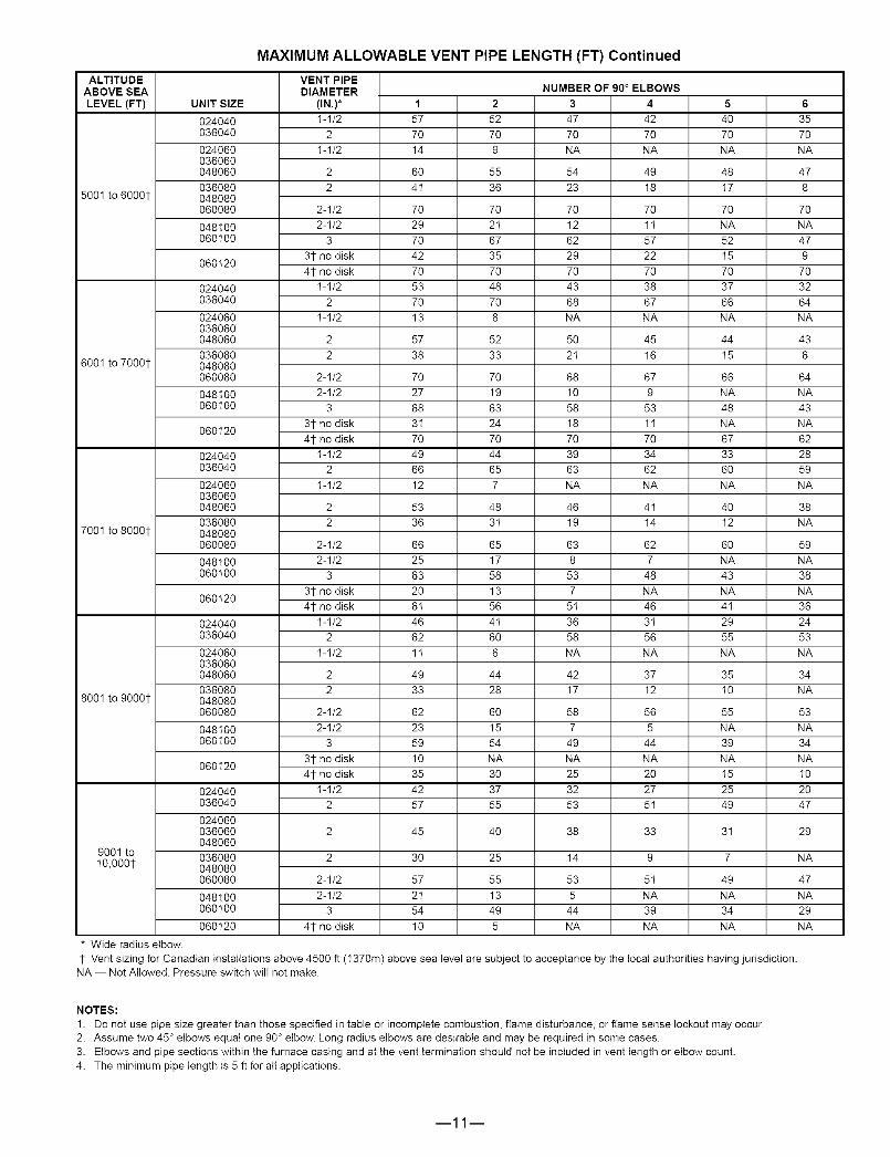
MAXIMUM ALLOWABLE VENT PIPE LENGTH (FT) Continued
ALTITUDEABOVE SEA
LEVEL (FT)
5001 to 60001-
6001 to 70001-
7001 to 80001-
8001 to 90001-
9001 toI0,0001-
* Wide radius elbow.
UNIT SIZE
024040036040
024060036060048060036080048080060080
048100060100
060120
024040036040
024060036060048060036080048080060080
048100060100
060120
024040036040
024060036060048060036080048080060080
048100060100
060120
024040036040
024060036060048060036080048080060080
048100060100
060120
VENT PIPEDIAMETER
(IN.)*I-I/2
2
I-I/2
22
2-I/2
2-I/23
31-no disk41-no disk
I-I/22
I-I/2
22
2-I/2
2-I/23
31-no disk41-no disk
I-I/22
I-I/2
22
2-I/2
2-I/23
31-no disk41-no disk
I-I/22
I-I/2
22
2-I/2
2-I/23
31-no disk41-no disk
I-I/22
1
577O
14
6O4I
7O
297O
427O
537O
13
5738
7O
2768
3I7O
4966
12
5336
66
2563
2O6I
4662
1I
4933
62
2359
1035
4257
2
52
70
9
55
36
70
2I
67
35
70
48
70
8
52
33
70
19
63
24
70
44
65
7
48
3I
65
17
58
13
56
4I
60
6
44
28
60
15
54
NA
30
37
55
5
40
70
NA
48
I7
70
NA
52
I5
70
37
66
NA
44
I5
66
NA
48
NA
67
33
6O
NA
4O
I2
6O
NA
43
NA
41
29
55
NA
35
I0
55
NA
39
NA
I5
25
49
NUMBER OF 90 ° ELBOWS3 4
47 4270 70
NA NA
54 4923 18
70 70
12 1I62 57
29 2270 70
43 3868 67
NA NA
50 452I 16
68 67
10 958 53
18 1I70 70
39 3463 62
NA NA
46 4I19 14
63 62
8 753 48
7 NA5I 46
36 3I58 56
NA NA
42 3717 12
58 56
7 549 44
NA NA25 20
32 2753 5I
38 33
14 9
53 5I
5 NA44 39
NA NA
6
35
70
NA
47
8
70
NA
47
9
70
32
64
NA
43
6
64
NA
43
NA
62
28
59
NA
38
NA
59
NA
38
NA
36
24
53
NA
34
NA
53
NA
34
NA
I0
2O
47
024040036040
024060036060 2 45 40 31 29048060
036080 2 30 25 7 NA048080060080 2-I/2 57 55 49 47
048100 2-I/2 2I 13 NA NA
060100 3 54 49 34 29
060120 41- no disk 10 5 NA NA
1- Vent sizing for Canadian installations above 4500 ft (I370m) above sea level are subject to acceptance by the local authorities having jurisdiction.NA -- Not Allowed. Pressure switch will not make.
NOTES:
1. Do not use pipe size greater than those specified in table or incomplete combustion, flame disturbance, or flame sense lockout may occur.
2. Assume two 45 ° elbows equal one 90 ° elbow. Long radius elbows are desirable and may be required in some cases.
3. Elbows and pipe sections within the furnace casing and at the vent termination should not be included in vent length or elbow count.
4. The minimum pipe length is 5 ft for all applications.
m11m

COMBUSTION-AIRPIPEFORNON-DIRECTVENTAPPLICATIONS
(Sizes 040 through 120 only)
._ FIELD-SUPPLIED2-IN. DIAMETER r- FIELD-SUPPLIED
PVC 90' ELBOW// 2-IN. DIAMETER
_" PVC PIPE
U-FA-_COMBUSTION-AIR DISC
(FACTORY-SUPPLIED INLOOSE PARTS BAG)
A96211
LENGTH OF STRAIGHT PIPE PORTION OF
COMBUSTION-AIR INLET PIPE ASSEMBLY (IN.)CASING WIDTH A
17-1/2 8-1/2 + 1/2
21 10-I/2 + I/2
24-1/2 12 + 1/2
ACCESSORIES
CONCENTRIC VENT(Direct Vent Applications Only)
B IN. DIA PVC
VENT/EXHAUST
I--- : .... :_
,-
._D,.. 11/2_._ _I3/_16 "_
l
L C IN. DIA
_ D "_J"
A--B IN. DIA PVC
INTAKE/COMBUSTION AIR
A97110
Note: See furnace Installation Instructions when venting multiple furnaces near each other.
DIMENSIONS (In.)
PART NO. A* B C Dt E F
KGAVTO50ICVT 33-3/8 2 3-I/2 16-5/8 6-I/4 5-3/4
KGAVT060ICVT 38-7/8 3 4-I/2 2I-1/8 7-3/8 6-1/2
* Dimension A will change accordingly as dimension D is lengthened or shortened.1- Dimension D may be lengthened to 60 in. maximum. Dimension D may also be shortened by cutting
the pipes provided in the kit to 12 in. minimum.
i12i

ACCESSORIES (Continued)
SIDE FILTER RACK*
A80199
*Accepts one 16 x 25 x 1 in. filter.
ACCESSORY DOWNFLOW SUBBASE
114"TYP
OPENING
FACTORY-SUPPLIED.FIELD-INSTALLED
INSULATION
Disassembled
A88207
Assembled
A97427
FURNACECASINGWIDTH
17-I/2
2I
24-I/2
FURNACE IN DOWNFLOW APPLICATION
Furnace with or without CD5, CK5 CoilAssembly or KCAKC Coil Box
Furnace with or without CD5, CK5 CoilAssembly or KCAKC Coil Box
Furnace with or without CD5, CK5 CoilAssembly or KCAKC Coil Box
* The plenum should be constructed 1/4dn. smaller in width and depth than the plenum dimensions shown above.
PLENUM OPENING*
A B
15-I/8 19
18-5/8 19
22-I/8 19
FLOOR OPENING
C D
I6-3/4 20-3/8
20-1/4 20-3/8
23-3/4 20-3/8
HOLE NO.FOR WIDTH
ADJUSTMENT
3
2
I
i13i

CLEARANCETOCOMBUSTIBLES
• This forced air fumace is equipped for use with naturaUgas at amtitudes 0 - 10,000 ft (0 m3,050m), except t40 size furnaces are onUy approved for aUtitudes 0 - 7,000 ft.(0 _2,135m).
o An accessory kit, suppJ_ed by the manufacturer, shah be used to convert toprepene gas use or may be required for some naturaUgas appUicetions.e This furnace is for indoor installation in a building constructed on site. This furnace may be installed in a manutactured (mobiKe) home when stated on rating plate and
using factory authorized kit..• This furnace may be instaIKed on cembustible flooring in alceve or deset at Minimum inches C|earance To Combusflb|e Construction as described below.• This furnace requires a special venting system. Refer to the installation in_ractbns for parts Uistand method of installation. This furnace is for use with scheduUe40 PVC,
PVC_DV_A/, CPVC, or ABS-DVVV pipe, and must not be vented in common with other gas-fired appUiances. Construction through which vent/air intake pipes may beinstalled is maximum 24 inches (610 ram), minimum 3/4 inches (19 ram) thickness (incUuding rooting matedals).
® Carte foumaise & air puls6 est 6quippe pour ufllisation avec gaz naturel et a_udes comprises entre 0 - 3,050m (0 - 10,000 pi),except6 queles foumaises de 140 tailmesent pour a_tudes compnses entre 0 - 2,135m (0 - 7,0OOpi).
• UtiUiserune trousse de conversion, foumie par mefabricant, pour passer au gaz propane ou pour cerLaines instaMations au gaz natureL• Cette foumaise & air puls6 est pour installation & I'intCrieur dans un b&timent consbreit sur place. Cette foumaise & air pulse peut _tre install6e dans une maison
prefabflquce (maisen mobiUe) si prescflt par mapUaque signamCtiqueet si'Uon utiUiseone treusse specifi6e par mefabricant.o _ette foureaise peut _tre install_ surun plancher sembustible dans un enfencement ou un placard en observant les D_gagement Mtairnu_ En Pouces Avec
E|6ments De Consttu_ion CombuetJbmee.® Cette foumaise n@_site on syst_me d'6vacuation sp_ciaJ. La m6thc<te d'instaHation et la Uistedes pieces n_ssaires flgurent dans Uesinstructions d'it_stalmatior_.Cette
foumaise dot s'u,flmiseravec _atuyauterie des nomenclatures 40 PVC, PVC_DVW, CPVC, ou ABSoDWV et e_e ne peat pes _ venti_e coojointment avec d'autresapperei_s a gaz. Epeisseur de la constm_on au travers de lequelle il est possible de faire passer Ins tuyaux d'a_ration (admission/6vacuation}: 24 pc (610 ram)maximum, 3/4 pe (19mm) minimum (y compris la toture).
For upSow and dcwnflow aplc_ications, furnace must be inst£1Hedbve], or pitched w_thin 1/2" of _ev_. For a M_N 1/4" TO 1/2" MAXhorizontal application, the furnace must be pitc_hedminimum 1/4" to maximum of 1/2" forward for properdrainage. See Installation Manual for _MPORTANT unit support details on berizootal app{ications.
Pour des appl_tJons de flux ascendar_ et descendant, la foumaise dot _t_e instalbe de nMsau ou indin6epes plus de 1/2" du niveau. Pour une ap#i_oo hodseeta_e, la fourcaLse dot _lre indir_e entre minimum UPFLOW1/4" et maximum 112" da niveau pour Redrainage apprepri& En ces d'instaSation en positk.)nhorizontab,
_lNl_U_ iNCHES CLEARANCE TO CO_BUSTIBLE CONSTRUCTIONALL POSmONS:
Minimum front c_earance for service 24 inches (610ram).1-1 140 size furnaces require 1 inch back clearance to Combustible materials.
DOWNFLOW POSmONS:
t: Forinstallatioooncembustiblefor_soolywheninstalledonspecia_baseNo. KGASBO2OIALL
Coil Assemb_, Part No. CD5 or CK5, or Coil Casing, Part No. KCAKC.
HORIZONTAL POSmONS:
Line contact is permissible only between lines formed by intersections d top and two sides of
furnace jacket, and building joists, studs, or framing.
§ Clearance shown is for air inlet and air outlet ends.
120 and 140 size farnaces require 1 inch bottom clearance to cornbustib_e materials.DEGAGE_ENT _INI_U_ EN POUCES AVEC ELEMENTS DE CONSTRUCTION COmBUSTiBLES
POUR TOU$LES POSmONS:D_agement avant minimum de 24 pc (610mm) pour I'entzetien.
1 1 Pour Ins foumaises de 140 tail_e, 1 pc (25rnm) d_gagement des materiaux cembustibles estreqUiS au-_rr_ere.
POURLA POSmON COURANT DESCENDANT:1" Pour _'instaHation sur le plancher combustible seulement quand on utilise la base s_ciale, piece
n° KdGASBO2OIALL, _'eesemble serpentin, piece n° CD5 ou CKe, ou le carter de serpentin,piC,cen ° KCAKC.
POUR LA POSmON NOR_ZONTALE:Le contact n'est perrnis qL_entre les _ignes for[Tl_es par Ins intersections du de,_sus et desdeuxc6tes de la chemise de la foumaise, et des so_ives, des montan#_ ou de _acharpente dub_timent.
§ La distance indiquee oonceme I'extt_mite du tuyau d'arriv6e d'air et I'exCr_mit_ du tuyau de sortied'air.Pour les foumaises de 120 et 140 taille, 1 po (25ram) d_agement des mat6riaux combusitbbsest requis au_essous,
This furnace isapproved for UPFLOW,DOWNFLOW andHORIZONTAL insta_ations.
Cette foumaise est approuv_e pour [installation HORIZONTALEet la drculation d'air VERS LE HAUT et VERS LE BAS.
C_earanceanows
do not change with ne change pas avecfurnace orientation. Fedentationde _a
g¢n@rateurd'air chaud.
Clearance in inches
D_gagement (pc).
'gent clearance tocombustibles O".
0(po) Degagementd'_vent avec combustibles.
328066-20! REV.C
14

AIR DELIVERyICFM (With Filter)*
EXTERNAL STATIC PRESSURE (In. wc)RETURN-AIR
UNIT SIZE SUPPLY SPEED 0.1 0.2 0.3 0.4 0.5 0.6 0.7 0.8
1 side High 1075 I040 995 945 895 840 760 670024040 or Med-Low 850 825 780 740 685 635 560 480
bottom Low 740 700 650 620 565 515 455 385
High 1470 I4 I5 I400 1285 1215 1120 995 8901 side Med-High 1315 I280 I235 1180 1115 I035 930 825
036040 or Med-Low 1I25 11 t0 I085 1045 990 915 830 740bottom Low 930 925 910 850 830 770 705 635
1 side High 1I00 I065 I005 945 900 805 730 610024060 or Med-Low 890 865 810 765 705 620 540 475
bottom Low 745 710 670 625 565 505 425 360
High 1430 I375 I325 1275 1200 1135 I040 9351 side Med-High 1270 I260 I215 1160 1105 I035 950 850
036060 or Med-Low 1070 I055 I045 1015 975 920 850 750bottom Low 915 895 885 865 840 800 720 650
High 1700 I695 I640 1580 1545 I450 I380 13101 side Med-High 1500 I465 I435 1385 1355 I300 I250 1185
048060 or Med-Low 1325 I295 I265 1230 1190 I150 I105 1050bottom Low 1205 1170 1145 1110 1080 I035 990 950
High 1535 I470 I405 1330 1245 1160 I065 9351 side Med-High 1395 I350 I300 1225 1I55 I080 985 880
036080 or Med-Low 1200 1175 1125 1065 1030 970 890 780bottom Low 1040 I020 990 960 910 860 785 680
High 1750 I685 I635 1575 1525 I445 I380 13101 side Med-High 1495 I455 I405 1355 1305 I250 I185 1120
048080 or Med-Low 1310 I260 I225 1170 1125 I095 I040 980bottom Low 1I35 1105 I075 1040 995 995 910 860
High 2200 2175 2085 2025 1925 I820 I735 16351 side Med-High 2100 2025 I945 1865 1785 I700 I620 1540
or Med-Low 1815 I760 I720 1670 1620 I550 I480 1405bottom
060080 Low 1560 I555 I515 1460 1435 I390 I340 1270
both sides or High 2360 2280 22I 0 2I 30 2035 1960 1875 1790I side and Med-High 1965 I925 I870 1830 1760 I710 I670 1575
bottom
High 1740 I705 I660 1615 1570 I500 I425 13551 side Med-High 1500 I470 I445 1410 1375 I330 I280 1210
048100 or Med-Low 1340 I315 I300 1270 1235 I200 I140 1095bottom Low 1I95 1175 1165 1 I30 1I00 I070 I030 975
High 2250 2175 2090 2020 1930 1855 1760 16701 side Med-High 2020 I950 I900 1840 1790 I7t0 I640 1545
or Med-Low 1725 I690 I660 1630 1575 I520 I460 1370bottom
060100 Low 1490 I480 I460 1440 1380 I340 I295 1230
both sides or High 2360 23t 5 2265 2200 2I 30 2055 1965 1890I side and Med-High 1960 I940 I930 1900 1850 I800 I740 1660
bottom
High 2350 2250 2160 2070 2000 I885 I790 1635bottom Med-High 2100 20t5 I955 1875 1810 I710 I650 1540
only Med-Low 1770 I720 I675 1620 1575 I5t5 I450 1365Low 1545 I520 I465 1415 1365 I325 I265 1 I85
060120 both sides or High 2435 2360 2285 2220 2I 30 2050 1965 1875I side and Med-High 2040 2000 I950 1905 1835 I790 I725 1650
bottom
High 2255 2190 21 I5 2045 1965 I890 I800 1710I side only Med-High 1985 I930 I890 1840 1780 I720 I645 1560
High 2285 2210 2140 2065 1990 I910 I830 1745bottom Med-High 2020 I970 I920 1870 1805 I730 I660 1590
only Med-Low 1675 I650 I620 1590 1560 I510 I450 1390Low 1460 I445 I430 1400 1370 I320 I275 1230
060140 both sides or High 2310 2255 2185 2120 2045 I965 I880 1800I side and Med-High 1975 I945 I900 1860 1835 I775 I720 1640
bottom
High 2140 2080 2025 1945 1875 I795 I725 1625I side only Med-High 1930 I850 I800 1740 1725 I660 I580 1495
A filter is required for each return-air supply.
* For horizontal and downflow applications, use "1 side or bottom" or "bottom only" as airflow reference.
i15i

© 2004 Payne Heating & Cooling 7310 West Morris Street. Indianapolis, IN 46231
1lcating& Cooling
--16--
SPECIFICATIONS SUBJECT TO CHANGE WITHOUT NOTICE
UNIT MUST BE INSTALLED IN ACCORDANCEWITH INSTALLATION INSTRUCTIONS
Cancels: SS-PG9M-04
PRINTED IN U.S.A. Catalog No 52PG-9M5 9-04