
IJCSMC, Vol. 5, Issue. 6, June 2016, pg.23 Indoor ... M. Ali et al, International Journal of...
18
Hamid M. Ali et al, International Journal of Computer Science and Mobile Computing, Vol.5 Issue.6, June- 2016, pg. 23-40 © 2016, IJCSMC All Rights Reserved 23 Available Online at www.ijcsmc.com International Journal of Computer Science and Mobile Computing A Monthly Journal of Computer Science and Information Technology ISSN 2320–088X IMPACT FACTOR: 5.258 IJCSMC, Vol. 5, Issue. 6, June 2016, pg.23 – 40 Indoor Pedestrian Tracking System Using Smartphone Hamid M. Ali 1 , Ahmed M. Hadi 2 1 Computer Engineering Dept., Baghdad University, Iraq 2 M.Sc. Student, Computer Engineering Dept., Baghdad University, Iraq 1 [email protected], 2 [email protected] Abstract---- Buildings nowadays have become very complicated which increases the need for a solution that helps offices tracking people for safety and security. One of the active solutions that address the above mentioned issue is the indoor tracking systems. Traditional camera based indoor tracking is static and tedious task. As the smartphone become an integrated part of human daily life with its capability of connecting to Wi-Fi network together with its inertial sensors can be used as a tool in tracking systems. The Global Position System (GPS) are commonly used for tracking in outdoor environment and are not accurate in indoor environment. The idea of the proposed system is to exploit the Wi-Fi access points, inside the building, together with smartphone accelerometer sensor for constructing accurate and reliable indoor pedestrian tracking system which lets the building administrator to watch and track pedestrians, carrying smartphones, wherever they move inside the building. Also, it is preferable that a user track path is sketched on real building map presented at the administrator monitor screen. This work consists of offline phase which is responsible for recording Wi-Fi fingerprint, while an online phase is used to determine and track user locations. This work mainly depends on Wi-Fi fingerprinting technique for locating the user in the building. But due to the instability of Wi-Fi signal, the localization task does not provide sufficient accuracy for spotting a correct user tracking path. To overcome from such localization insufficient accuracy, the proposed system exploited a matrix, constructed during offline phase that offer a legible path between building locations, and used to reform the correct path. Keywords: Indoor Tracking system, GPS, Smartphones, Smartphone accelerometer sensor, ArcGIS, Wi-Fi Fingerprinting I. Introduction Recently, there has been growing interest in Location-Based Services (LBS). Especially, with the widespread use of smartphones, developing a tracking scheme has become an important research issue. GPS are the most commonly used technique in tracking applications and find the device location; it provides high accuracy in outdoor environment. GPS receives the signal from different satellites to determine the device location, so that a line of sight (LoS) between satellites and device is obvious. However, the GPS signal is an ineffective inside
Transcript of IJCSMC, Vol. 5, Issue. 6, June 2016, pg.23 Indoor ... M. Ali et al, International Journal of...

Hamid M. Ali et al, International Journal of Computer Science and Mobile Computing, Vol.5 Issue.6, June- 2016, pg. 23-40
© 2016, IJCSMC All Rights Reserved 23
Available Online at www.ijcsmc.com
International Journal of Computer Science and Mobile Computing
A Monthly Journal of Computer Science and Information Technology
ISSN 2320–088X IMPACT FACTOR: 5.258
IJCSMC, Vol. 5, Issue. 6, June 2016, pg.23 – 40
Indoor Pedestrian Tracking
System Using Smartphone
Hamid M. Ali
1, Ahmed M. Hadi
2
1Computer Engineering Dept., Baghdad University, Iraq 2M.Sc. Student, Computer Engineering Dept., Baghdad University, Iraq
1 [email protected], 2 [email protected]
Abstract---- Buildings nowadays have become very complicated which increases the need for a solution that
helps offices tracking people for safety and security. One of the active solutions that address the above
mentioned issue is the indoor tracking systems. Traditional camera based indoor tracking is static and
tedious task. As the smartphone become an integrated part of human daily life with its capability of
connecting to Wi-Fi network together with its inertial sensors can be used as a tool in tracking systems. The
Global Position System (GPS) are commonly used for tracking in outdoor environment and are not accurate
in indoor environment. The idea of the proposed system is to exploit the Wi-Fi access points, inside the
building, together with smartphone accelerometer sensor for constructing accurate and reliable indoor
pedestrian tracking system which lets the building administrator to watch and track pedestrians, carrying
smartphones, wherever they move inside the building. Also, it is preferable that a user track path is sketched
on real building map presented at the administrator monitor screen. This work consists of offline phase which
is responsible for recording Wi-Fi fingerprint, while an online phase is used to determine and track user
locations. This work mainly depends on Wi-Fi fingerprinting technique for locating the user in the building.
But due to the instability of Wi-Fi signal, the localization task does not provide sufficient accuracy for
spotting a correct user tracking path. To overcome from such localization insufficient accuracy, the proposed
system exploited a matrix, constructed during offline phase that offer a legible path between building
locations, and used to reform the correct path.
Keywords: Indoor Tracking system, GPS, Smartphones, Smartphone accelerometer sensor, ArcGIS, Wi-Fi
Fingerprinting
I. Introduction
Recently, there has been growing interest in Location-Based Services (LBS). Especially, with the widespread use
of smartphones, developing a tracking scheme has become an important research issue. GPS are the most
commonly used technique in tracking applications and find the device location; it provides high accuracy in
outdoor environment. GPS receives the signal from different satellites to determine the device location, so that a
line of sight (LoS) between satellites and device is obvious. However, the GPS signal is an ineffective inside

Hamid M. Ali et al, International Journal of Computer Science and Mobile Computing, Vol.5 Issue.6, June- 2016, pg. 23-40
© 2016, IJCSMC All Rights Reserved 24
building due to the poor signals of satellites, dispersion of the signal [1]. In [2] an indoor tracking system using
Bluetooth technique is presented. This system needs additional hardware, Bluetooth adapter, for the purpose of
finding the location of the user in the building which increases the cost of the system. It uses at least three
Bluetooth APs to determine user location which imposes a constraint on the infrastructure of the building. Also,
the monitoring service in this system does not use a real map to reflect any interface reality of the building.[3]
Presents a location providing technique for self-location tracking using smartphone. This system is using the
inertial sensors available in smartphone (accelerometer and magnetometer) and Wi-Fi APs to provide physical
and logical location tracking services. Logical location service is generated from the signal properties of Wi-Fi
APs. Physical location tracking service based on the Dead Reckoning (DR). This service uses network location
provider to get the initial physical location and periodically revise the DR accumulated error. Such provider
gives inaccurate location technique [4] [5]. Also this service implies the user to initially enter her/his length and gender to calculate the step length of each user. In [6] indoor monitoring system named Pazl is implemented
using Pedestrian Dead Reckoning (PDR) and Wi-Fi fingerprinting. PDR is prone to the accumulative error after
certain period of time [7]. This system uses the magnetometer sensor to verify whether the user is walking in the
same corridor or turns to another corridor. Actually, the direction measured by magnetometer sensor is prone to
error [4]. Also, this system depends on the Wi-Fi fingerprinting localization to correct the accumulative error
produced from the PDR process. The Wi-Fi fingerprint is also prone to shift error which is not reliable source of
determining user location. This system is developed to run on the cloud, such cloud processing could delay the
response time which is very important in tracking system. In [8] indoor customer tracking is implemented using
the advantage of the cell of origin (CoO) technique. This technique divides the area of interest into many small
cells/polygons. This method assigns a unique cell or polygon for each Wi-Fi AP. This approach determines the
user in any cell, based on RSS from AP. The localization accuracy in this system is based on the size of cells which in turn relying on the number of APs in the building. Hence, wherever the cell is getting larger, the
accuracy of the tracking system will decrease. The proposed system used Wi-Fi fingerprint technique to
determine user location inside the building together with smartphone accelerometer sensor to track the user. The
proposed system consists of two phases: the offline phase and the online phase.
The rest of the paper is organized as follows: Section II describes the offline phase mechanism. Section III
describes the online phase mechanism. Section IV describes the performance evaluation of the proposed system.
Finally, section V concludes the paper.
II. Offline Phase
Fig1 shows the main components used in the offline phase. The administrator smartphone is loaded with
software that is responsible for handling the offline phase.
Fig 1 Offline Phase Components

Hamid M. Ali et al, International Journal of Computer Science and Mobile Computing, Vol.5 Issue.6, June- 2016, pg. 23-40
© 2016, IJCSMC All Rights Reserved 25
The following steps describe the functions of the offline phase conducted by the administrator:
1. The administrator passes through the whole building regions recording the MAC addresses of the building
APs and excluding all the APs that are detected and do not belong to the building.
2. At each preassigned location in the building, called RP, the administrator smartphone detects and collects a
vector of the entire APs Wi-Fi RSS fingerprint detected at that RP. Then each vector of each RP, together
with RP identification name, are sent and stored at the building database server. In this work, the RPs are
selected in all corridors and rooms of the building with 2.5 meter distance between each two adjacent RPs.
3. Also at the offline phase, each RP in the real building map is accurately positioned relative to the map
georeferencing presented on the administrator monitor screen. The real map of the building with associated
positioning of the RPs is saved in the database server to be retrieved at the online phase for displaying user
track path.
A. Real Building Map Georeferencing
Real map reflects the true reality of the environment which helps the administrator to view the user tracking
path when they are moving inside the building. The real building map and its assigned RPs have to be accurately
projected at the administrator monitoring screen. To facilitate the projection process, the Open Street Map
(OSM) with ArcGIS system is used to project the real building map with its associated RPs on their exact
locations on the screen map corresponding to their real locations in the building. Each RP is projected on its
exact location on the map by equal distance between them, 2.5m, as shown in fig 2.
Fig 2 RPs Positioned on their Exact Location on the Map
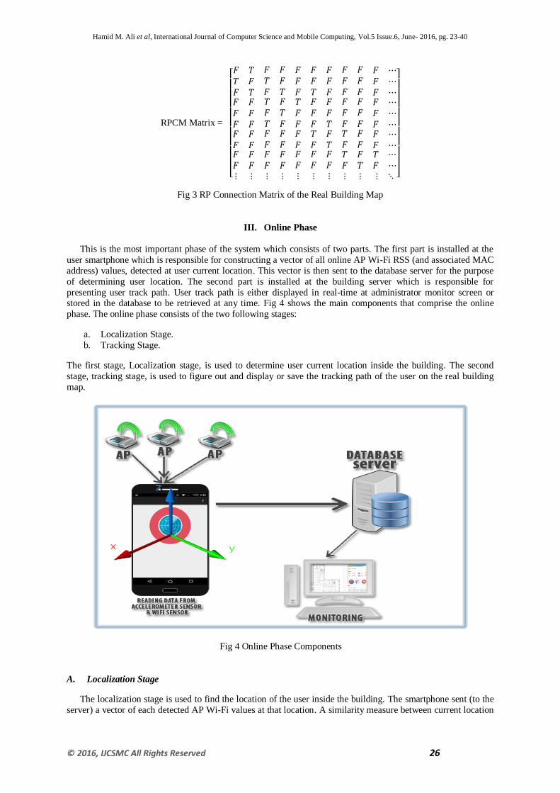
B. Reference Points Connection Matrix
For the purpose of determining user path, during tracking time, it is found essential for the system to
recognize the path between successive and neighbor RPs. Therefore, RPs connection matrix (RPCM) is
constructed during offline phase to link the RPs that have path between them. RPCM is constructed as shown in
fig 3 which illustrates the connection path between RPs in the real building map shown in fig 2.
Where:
RPCM (i, j): is square matrix.
i: symbolizes the row of the matrix which its value is from 1 to number of RPs.
j: symbolizes the column which its value from 1 to number of RPs.
Each item in the matrix contains either T or F. For example the value of RPCM (3, 6) is T which indicates that
there is a path between RP3 and RP6, while the value of RPCM (2, 7) is F which indicates that there is no path
between RP2 and RP7.
Hamid M. Ali et al, International Journal of Computer Science and Mobile Computing, Vol.5 Issue.6, June- 2016, pg. 23-40
© 2016, IJCSMC All Rights Reserved 26
RPCM Matrix =
[
]
Fig 3 RP Connection Matrix of the Real Building Map
III. Online Phase
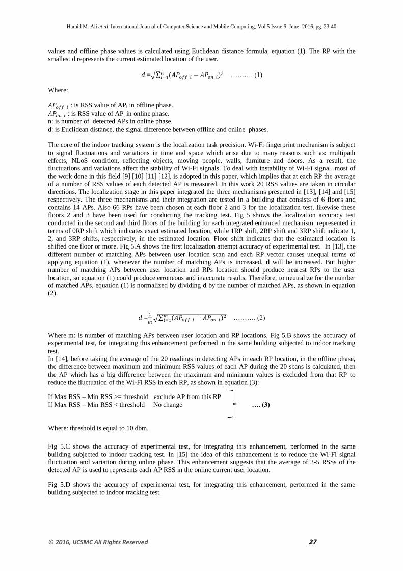
This is the most important phase of the system which consists of two parts. The first part is installed at the
user smartphone which is responsible for constructing a vector of all online AP Wi-Fi RSS (and associated MAC
address) values, detected at user current location. This vector is then sent to the database server for the purpose
of determining user location. The second part is installed at the building server which is responsible for
presenting user track path. User track path is either displayed in real-time at administrator monitor screen or stored in the database to be retrieved at any time. Fig 4 shows the main components that comprise the online
phase. The online phase consists of the two following stages:
a. Localization Stage.
b. Tracking Stage.
The first stage, Localization stage, is used to determine user current location inside the building. The second
stage, tracking stage, is used to figure out and display or save the tracking path of the user on the real building
map.
Fig 4 Online Phase Components
A. Localization Stage
The localization stage is used to find the location of the user inside the building. The smartphone sent (to the
server) a vector of each detected AP Wi-Fi values at that location. A similarity measure between current location
Hamid M. Ali et al, International Journal of Computer Science and Mobile Computing, Vol.5 Issue.6, June- 2016, pg. 23-40
© 2016, IJCSMC All Rights Reserved 27
values and offline phase values is calculated using Euclidean distance formula, equation (1). The RP with the
smallest d represents the current estimated location of the user.
=√∑
………. (1)
Where:
: is RSS value of APi in offline phase.
: is RSS value of APi in online phase.
n: is number of detected APs in online phase.
d: is Euclidean distance, the signal difference between offline and online phases.
The core of the indoor tracking system is the localization task precision. Wi-Fi fingerprint mechanism is subject
to signal fluctuations and variations in time and space which arise due to many reasons such as: multipath
effects, NLoS condition, reflecting objects, moving people, walls, furniture and doors. As a result, the
fluctuations and variations affect the stability of Wi-Fi signals. To deal with instability of Wi-Fi signal, most of
the work done in this field [9] [10] [11] [12], is adopted in this paper, which implies that at each RP the average
of a number of RSS values of each detected AP is measured. In this work 20 RSS values are taken in circular
directions. The localization stage in this paper integrated the three mechanisms presented in [13], [14] and [15] respectively. The three mechanisms and their integration are tested in a building that consists of 6 floors and
contains 14 APs. Also 66 RPs have been chosen at each floor 2 and 3 for the localization test, likewise these
floors 2 and 3 have been used for conducting the tracking test. Fig 5 shows the localization accuracy test
conducted in the second and third floors of the building for each integrated enhanced mechanism represented in
terms of 0RP shift which indicates exact estimated location, while 1RP shift, 2RP shift and 3RP shift indicate 1,
2, and 3RP shifts, respectively, in the estimated location. Floor shift indicates that the estimated location is
shifted one floor or more. Fig 5.A shows the first localization attempt accuracy of experimental test. In [13], the
different number of matching APs between user location scan and each RP vector causes unequal terms of
applying equation (1), whenever the number of matching APs is increased, d will be increased. But higher
number of matching APs between user location and RPs location should produce nearest RPs to the user
location, so equation (1) could produce erroneous and inaccurate results. Therefore, to neutralize for the number of matched APs, equation (1) is normalized by dividing d by the number of matched APs, as shown in equation
(2).
=
√∑
………. (2)
Where m: is number of matching APs between user location and RP locations. Fig 5.B shows the accuracy of
experimental test, for integrating this enhancement performed in the same building subjected to indoor tracking
test.
In [14], before taking the average of the 20 readings in detecting APs in each RP location, in the offline phase,
the difference between maximum and minimum RSS values of each AP during the 20 scans is calculated, then
the AP which has a big difference between the maximum and minimum values is excluded from that RP to
reduce the fluctuation of the Wi-Fi RSS in each RP, as shown in equation (3):
If Max RSS – Min RSS >= threshold exclude AP from this RP
If Max RSS – Min RSS < threshold No change …. (3)
10 dbm. Where: threshold is equal to
Fig 5.C shows the accuracy of experimental test, for integrating this enhancement, performed in the same
building subjected to indoor tracking test. In [15] the idea of this enhancement is to reduce the Wi-Fi signal
fluctuation and variation during online phase. This enhancement suggests that the average of 3-5 RSSs of the
detected AP is used to represents each AP RSS in the online current user location.
Fig 5.D shows the accuracy of experimental test, for integrating this enhancement, performed in the same
building subjected to indoor tracking test.

Hamid M. Ali et al, International Journal of Computer Science and Mobile Computing, Vol.5 Issue.6, June- 2016, pg. 23-40
© 2016, IJCSMC All Rights Reserved 28
Fig 5: (A) Accuracy of the First Experimental Test (B) Localization Accuracy of the First Enhancement (C)
Localization Accuracy of the Second Enhancement (D) Localization Accuracy of the Third Enhancement
B. Tracking Stage
This stage encompasses the main objective of this work which is responsible for tracking the user, then
reflecting and viewing user track path in real-time or non-real-time on the real building map display. Once the
indoor tracking system is activated on user smartphone, the following interleaved and overlapped operations and
functions, on the server side and smartphone side, are performed:
1. First, the software implemented at the user smartphone reads and sends to the server all the detected AP
RSS values at the user current location. Second, at the server side the localization stage is activated to
compute and find user current location. For example, at the beginning of the tracking journey the
localization stage initially located the user near RP1 as initial location of the tracking path starting point.
This action is reflected at the monitor screen by highlighting RP1 by blue color at the real building map as shown in fig 6.
Fig 6 Highlighted RP1 in Real Time Tracking
0%
10%
20%
30%
40%
50%
60%
70%
80%
90%
100%
AB
CD
0RP Shift
1RP Shift
2RP Shift
3RP Shift
floor Shift

Hamid M. Ali et al, International Journal of Computer Science and Mobile Computing, Vol.5 Issue.6, June- 2016, pg. 23-40
© 2016, IJCSMC All Rights Reserved 29
2. On each user stride, detected by smartphone accelerometer sensor, the user smartphone reads and sends to
the server all the detected AP RSS values at the user new location, in other words, finding the nearest RP to
the user new location. Then the server, upon receiving new AP RSS values, the localization stage is
executed again. This step is repeated until a new RP is found. For example, if RP1 is detected in step 1
above then the system searches for the next RP linked to RP1 as specified in RPCM which is RP2. Also,
RP2 is highlighted by blue color, on the real building map display, to illustrate where the user has arrived in
his journey, as shown in fig 7.
Fig 7 Highlighted of RP2 in Real Time Tracking
3. The real-time track path information is stored, in the server database, such as user ID, date and time as archive. The proposed system provides the ability to view the user track path in non-real-time state which let
the administrator to display the track path of specific user in certain period of time.
4. If the system, after detection RP1, detects a RP other than RP2 which indicates that the localization task has
produced RP shift error. This phenomenon is fully explained and analyzed later using a mechanism that
make the system recovers from some of the localization shift error.
5. The localization stage is not activated if the user is in steady state, not moving, detected by
smartphone accelerometer sensor. This reduces the computation process on the smartphone
which in turn minimize power consumption of the smartphone battery.
C. Improving Tracking Stage Accuracy
The tracking stage accuracy is completely based on the localization stage in determining user location and
track path construction. To recover from some RP shift error produced from the localization stage and improve
indoor tracking system accuracy, the RP connection matrix, created in the offline phase, is exploited to recover
from some RP shifts error. The following improvement cases illustrate how the tracking stage recovers from
some of the RP shift errors and then reforms the correct path:
Case 1: Referring to fig 8, suppose the system after currently locating the user at RP5, the user starts moving
either toward RP2 or toward RP6. The system expected to find RP2 or RP6 as long there are links between RP5
and RP2 from one side and RP6 from the other side, respectively. Hence, if the system detected RP1, RP3, RP4,
RP7, RP8 or RP9 instead, then the system concludes that one linked RP shift is occurred as long as there are
links between RP2 and RP1, RP3, and RP4 from one side and between RP6 and RP7, RP9, and RP8 from the other side. For example, if RP7 is detected while the user is moving toward RP6 and as long as there is no link
from RP5 to RP7 and there is a link between RP6 and RP7, then the system decides that this case is one linked
RP shift and the user must pass through RP6 to reach RP7. Hence, the system regards that RP6 is the next
located RP, in the tracking path, after RP5. Then the system, as long as the user is moving, starts to look for the

Hamid M. Ali et al, International Journal of Computer Science and Mobile Computing, Vol.5 Issue.6, June- 2016, pg. 23-40
© 2016, IJCSMC All Rights Reserved 30
expected RP (the next linked RP in the path) of RP6 (RP5, RP7, RP8, or RP9) in the same manner explained
above.
Fig 8 Connected RPs Prototype
Case 2: Referring to fig 9, suppose the system after currently locating the user at RP6, the user starts moving
either toward RP3 or toward RP7. The system expected to find RP3 or RP7 as long there are links between RP6 and RP3 from one side, and RP7 from other side, respectively. If the system detected the user at RP1 or RP11
which will be called 2 linked RP shift since RP1 or RP11 have no direct link to RP3 or RP7 respectively. Then
the system concludes that the user is proximate to RP3 if RP1 is located, as there is no direct path between RP3
and RP1. Otherwise the system concludes that the user is proximate to RP7 if RP11 is located, as there is no
direct path between RP7 and RP11. Then the system starts searching for the next expected RP of RP3 or of RP7.
Fig 9 Connected RPs Prototype
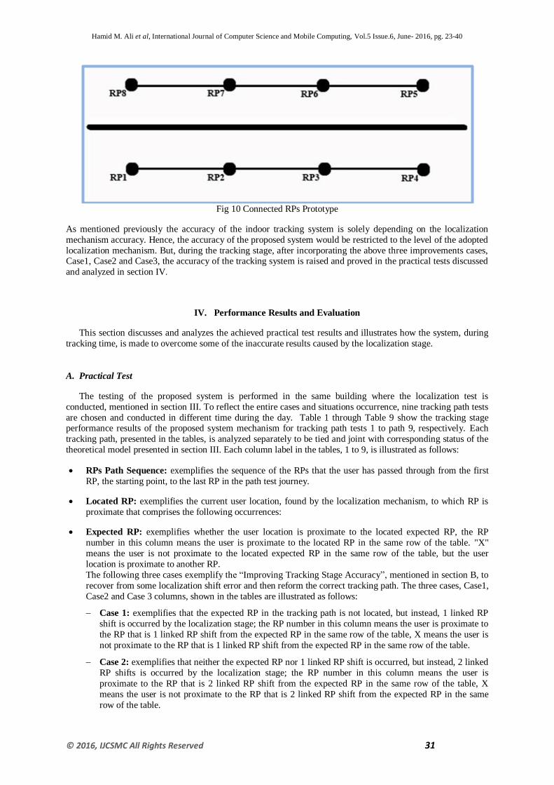
Case3: This case is concerned with locating RP that is neither expected RP nor 1 linked RP shift and nor 2
linked RP shift. Referring to fig 10, the thick dark black line represents, for example, a wall that prevents a path
(link) between upward and downward RPs. Now suppose the system after currently locating the user at RP1, the
user starts moving toward expected RP, which is RP2, and the system located the user for example at R8 or RP7
which are neither expected RP nor 1 linked RP shift and nor 2 linked RP shift. Then the system is configured to
ignore the current detected RP and wait for successive localization attempts, performed on each user stride, until
the excepted RP, Case1 or Case2 is occurred which will be treated as accepted status as explained above.
Hamid M. Ali et al, International Journal of Computer Science and Mobile Computing, Vol.5 Issue.6, June- 2016, pg. 23-40
© 2016, IJCSMC All Rights Reserved 31
Fig 10 Connected RPs Prototype
As mentioned previously the accuracy of the indoor tracking system is solely depending on the localization
mechanism accuracy. Hence, the accuracy of the proposed system would be restricted to the level of the adopted
localization mechanism. But, during the tracking stage, after incorporating the above three improvements cases, Case1, Case2 and Case3, the accuracy of the tracking system is raised and proved in the practical tests discussed
and analyzed in section IV.
IV. Performance Results and Evaluation
This section discusses and analyzes the achieved practical test results and illustrates how the system, during
tracking time, is made to overcome some of the inaccurate results caused by the localization stage.
A. Practical Test
The testing of the proposed system is performed in the same building where the localization test is
conducted, mentioned in section III. To reflect the entire cases and situations occurrence, nine tracking path tests
are chosen and conducted in different time during the day. Table 1 through Table 9 show the tracking stage performance results of the proposed system mechanism for tracking path tests 1 to path 9, respectively. Each
tracking path, presented in the tables, is analyzed separately to be tied and joint with corresponding status of the
theoretical model presented in section III. Each column label in the tables, 1 to 9, is illustrated as follows:
RPs Path Sequence: exemplifies the sequence of the RPs that the user has passed through from the first
RP, the starting point, to the last RP in the path test journey.
Located RP: exemplifies the current user location, found by the localization mechanism, to which RP is
proximate that comprises the following occurrences:
Expected RP: exemplifies whether the user location is proximate to the located expected RP, the RP
number in this column means the user is proximate to the located RP in the same row of the table. "X"
means the user is not proximate to the located expected RP in the same row of the table, but the user
location is proximate to another RP.
The following three cases exemplify the “Improving Tracking Stage Accuracy”, mentioned in section B, to
recover from some localization shift error and then reform the correct tracking path. The three cases, Case1,
Case2 and Case 3 columns, shown in the tables are illustrated as follows:
Case 1: exemplifies that the expected RP in the tracking path is not located, but instead, 1 linked RP
shift is occurred by the localization stage; the RP number in this column means the user is proximate to
the RP that is 1 linked RP shift from the expected RP in the same row of the table, X means the user is
not proximate to the RP that is 1 linked RP shift from the expected RP in the same row of the table.
Case 2: exemplifies that neither the expected RP nor 1 linked RP shift is occurred, but instead, 2 linked
RP shifts is occurred by the localization stage; the RP number in this column means the user is
proximate to the RP that is 2 linked RP shift from the expected RP in the same row of the table, X
means the user is not proximate to the RP that is 2 linked RP shift from the expected RP in the same
row of the table.

Hamid M. Ali et al, International Journal of Computer Science and Mobile Computing, Vol.5 Issue.6, June- 2016, pg. 23-40
© 2016, IJCSMC All Rights Reserved 32
Case 3: exemplifies that the located RP is neither the expected RP nor 1 linked RP shift or 2 linked RP
shift the user is proximate to the RP in the same row of the table; the RP number in this column
represents this case.
1) Test 1: Fig 11.A shows the test path taken by the user from RP3 to RP25, as highlighted by blue color, in the
second floor of the building. The localization stage has detected the user smartphone correctly when the user
passes through RP3, RP6, RP7, RP11, RP14, RP20 and RP25 as indicated by the RP number in the
“Expected RP” column, as shown in table 1. Now when the user is moving from RP7 to RP8 the system
didn’t locate RP8, but instead, it located another RP that is 1 linked RP shift to RP8 as indicated by X sign in
the “Expected RP” column and RP11 in the “Case1 - One linked RP shift” column of the RP8 row.
Consequently, “Case1” of the “Improving Tracking Stage Accuracy” procedure is applied by the system which concluded, that as long as RP8 is linked to RP7 and RP11 has a direct link to RP8, then it is one linked
RP shift error has occurred and then the system considered RP8 is the next RP approached after RP7. After
locating the expected RPs, the same discussion of locating RP8 is applied when locating RP15 as shown in
the table. The tracking stage mechanism of this test has overcome and recovered from the localization error
of two 1 linked RP shift produced from the localization stage, illustrated in table1, and achieved the correct
tracking path shown in fig 11.B.
(A) (B)
Fig11 (A) Tracking Path in the Second Floor (B) Table 1: Tracking Path in the Second Floor
2) Test 2: Fig 12.A shows the test path taken by the user from RP61 to RP28, as highlighted by blue color, in
the second floor of the building, as shown in table 2, that the localization stage has detected the user
smartphone correctly when the user passes through RP61, RP58, RP55, RP54, RP39 and RP28. Now when
the user is moving from RP54 to RP49 the system didn’t locate RP49, but instead, it located another RP that
is 1 linked RP shift to RP49, as indicated by X sign in the “Expected RP” column and RP50 in the “Case1 -
One linked RP shift” column of the RP49 row. Consequently, “Case1” of the “Improving Tracking Stage
Accuracy” procedure is applied by the system which concluded, that as long as RP50 is linked to RP49 and
RP50 has a direct link to RP49, then it is one linked RP shift error has occurred and then the system
considered RP49 is the next RP approached after RP54. The new state in this test is when the user is moving
from RP43 to RP42, looking for the expected RP, the system located RP44 instead of RP42 as shown in the
RP42 row of the Fig12.B. Hence as long as RP44 is expected RP for RP43, the system considered the user proximate to RP44, which is highlighted by red color shown in fig 12.A, but in fact the user is moving to
RP42 not to RP44. Hence after, in the successive localization tasks, the system is looking for expected RPs of
RP44 which are RP43 and RP45 as shown in fig 12.A. In the next localization process, the system located the
user at RP43 which is expected RP of RP44.Then the system concluded that the user at RP43. In this state
RP44 is marked visited by the user which is not. The tracking stage mechanism of this test has overcome and
recovered from the localization error of 1 linked RP shift produced from the localization stage, illustrated in
table 2, but produced one RP shift misleading location, as explained above, when the system located RP44
which is not in the path of the user.

Hamid M. Ali et al, International Journal of Computer Science and Mobile Computing, Vol.5 Issue.6, June- 2016, pg. 23-40
© 2016, IJCSMC All Rights Reserved 33
(A) (B)
Fig12 (A) Tracking Path in the Second Floor (B) Table 2: Tracking Path in the Second Floor
3) Test 3: Fig 13.A shows the test path taken by the user from RP15 to RP49, as highlighted by blue color, in the second floor of the building. In table 3, RP25 and RP43 are not detected while the user is moving from
RP20 to RP25 and from RP42 to RP43 respectively. The new state in this test is when the user is moving
from RP27 to RP28, the localization stage located the user proximate to RP that is neither proximate to the
expected RP nor to the RP that has a link to the expected RP (1 linked RP shift). But instead it located two
linked RP Shift, RP32 that is connected to RP29 which in turn is connected to RP28. The X sign in the
“Expected RP”, “Case1” columns respectively and RP32 in the “Case2” column of the RP28 row reflects this
state of the test as shown in Fig13.B. In this state of the test, the system ignored the currently located RP and
considered RP28 is the next RP approached after RP27 as long as RP32 is 2 linked RP shift from RP28. The
rest of the tracking process in this test has achieved similar performance results as discussed in Test1 above
for locating RP39, RP42, RP43, RP48 and RP49 respectively, as indicated in the table. The tracking stage
mechanism of this test has overcome and recovered from localization errors of one and two linked RP shift produced from the localization stage.
(A) (B)
Fig13 (A) Tracking Path in the Second Floor (B) Table 3: Tracking Path in the Second Floor

Hamid M. Ali et al, International Journal of Computer Science and Mobile Computing, Vol.5 Issue.6, June- 2016, pg. 23-40
© 2016, IJCSMC All Rights Reserved 34
4) Test 4: Fig 14.A shows the test path taken by the user from RP109 to RP90, as highlighted by blue color, in
the third floor of the building. The localization stage of this test has detected the user smartphone correctly
when the user passes through RP109, RP108, RP105, RP93 and RP90, as shown in Fig14.B. When the
system detected RP105 and looking for the next expected RP. The X sign in the “Expected RP”, “Case1”
columns respectively and RP92 in the “Case2” column of the RP94 row reflects this state of the test. In this
state of the test, the system ignored the currently located RP and considered RP94 is the next RP approached
after RP105 as long as RP92 is 2 linked RP shift from RP94, as shown in the Fig14.A. The tracking stage
mechanism of this test has overcome and recovers from the localization error of 2 linked RP shift and twice 1
linked RP shift produced from the localization stage.
(A) (B)
Fig14 (A) Tracking Path in the Third Floor (B) Table 4: Tracking Path in the Third Floor
5) Test 5: Fig 15.A shows the test path taken by the user from RP32 to RP55 as highlighted by blue color in the
second floor of the building as shown in fig 15.B. The new state in this test is when the user is moving from
RP32 to RP29, looking for the expected RP, the system located RP31 instead of RP29 as shown in the
“Expected RP”, column of the RP29 row in fig 15.B. Hence as long as RP31 is expected RP for RP32, the
system considered the user proximate to RP31, which is, for clarity, manually highlighted by red color
shown in fig 15.A, while the user in fact is moving to RP29. In the next localization attempt the system
located the user proximate to RP32 which is regarded as expected RP to RP31. In the next localization
attempt RP28 is located which is 1 linked RP shift to the RP32. Hence, RP29 is highlighted as the next RP
visited by the user. The tracking stage mechanism of this test has one RP mistaken when the system located
the user at RP31 while the user, in reality, is moving to RP29. But in the rest of the path, the mechanism has overcome and recovered from the localization error of 1 linked RP shift produced from the localization stage.
(A) (B)
Fig15 (A) Tracking Path in the Second Floor (B) Table 5: Tracking Path in the Second Floor

Hamid M. Ali et al, International Journal of Computer Science and Mobile Computing, Vol.5 Issue.6, June- 2016, pg. 23-40
© 2016, IJCSMC All Rights Reserved 35
6) Test 6: Fig 16.A shows the test path taken by the user from RP38 to RP15, as highlighted by blue color
except the starting point with green color, in the second floor of the building as shown in Fig 16.B. The new
state in this test is when the user is at RP38 location, the system located the user at RP37 as starting point of
the path, as illustrated in fig 16.A, that RP38 is not highlighted as the first located RP but instead RP37 is
highlighted as first located RP. For clarity, RP38 is manually highlighted with green color, so that it wouldn’t
be confused with detected blue colored RPs. In the next localization attempts the system was still locating
RP37 which is normal operation as long as RP37 is the current located RP until RP36 was located as
expected RP of RP37. The tracking stage mechanism of this test mistakes the starting RP of the path when
the system located the user at RP37 while in reality the user is at RP38; consequently, RP38 is not presented
on the path. Also, RP39 is marked visited by the user which is not, as it is for clarity, manually highlighted by a red color. But in the rest of the path, the mechanism has overcome and recovered from the localization
error of 1 linked RP shift produced from the localization stage.
(A) (B)
Fig16 (A) Tracking Path in the Second Floor (B) Table 6: Tracking Path in the Second Floor
7) Test 7: Fig 17.A shows the test path taken by the user from RP75 to RP101, as highlighted by blue color in
the third floor of the building as shown in Fig 17.B. The new state in this test is when the user is moving
from RP91 to RP92, the system didn’t locate RP92, but instead, it located RP107. R107 is not expected RP
neither 1 nor 2 linked RP shift to RP92. The X sign in the “Expected RP”, “Case1”, “Case2” columns
respectively and RP107 in the “Case3” column of the RP92 row reflects this state of the test. In this state, the system ignored the currently located RP, i.e. RP107, and waited for the next repetitive localization
attempts, performed on each user stride, until the expected, 1 or 2 linked RP shift to RP92 is located. In this
test, the system, in the next localization attempt, located RP93 which is 1 linked RP shift to RP92 and treated
it as explained in the previous tests. Then the system proceeded with the rest of the path tracking correctly
until trying to find the excepted RP of the RP94; the system located RP95, which is manually highlighted
with red color as it is not visited by the user. Then in next localization attempt RP101 is located. The tracking
stage mechanism of this test has overcome and recovered from the localization error of 1 linked RP shift and
from one not linked RP shift error produced from the localization stage and achieved correct tracking path.
Except that the system has marked RP95 as it is visited by the user which is not.

Hamid M. Ali et al, International Journal of Computer Science and Mobile Computing, Vol.5 Issue.6, June- 2016, pg. 23-40
© 2016, IJCSMC All Rights Reserved 36
(A) (B)
Fig17 (A) Tracking Path in the Third Floor (B) Table 7: Tracking Path in the Third Floor
8) Test 8: Fig 18.A shows the test path taken by the user from RP88 to RP114, as highlighted by blue color in
the third floor of the building. The new state in this test when the user is at RP88 location, the system located
the user at RP86 as starting point of the path, as illustrated in fig 18.A that RP88, which is manually
highlighted with green color, as the first located RP but instead RP86 is highlighted as first located RP. In the
next localization attempt, RP87 is located as expected RP of RP86; hence RP87 is highlighted as the second
RP visited by the user after RP86. Also RP87 will be shown on the map as starting point of the user track
path. The tracking stage mechanism of this test mistakes the starting RP of the path when the system located
the user at RP86 while in reality the user is at RP88; consequently, RP88 is not presented on the path. For the
rest of user path, the tracking stage mechanism of this test has overcome and recovered from the localization error of one not linked RP shift and one linked RP shift produced from the localization stage, illustrated in
Fig 18.B.
(A) (B)
Fig18 (A) Tracking Path in the Third Floor (B) Table 8: Tracking Path in the Third Floor
9) Test 9: Fig 19.A shows the test path taken by the user from RP55 to RP37, as highlighted by blue color, in
the second floor of the building as shown in Fig 19.B. The new state in this test is when the user is moving
from RP43 to RP42, the system located RP47 instead of RP42. RP47 is neither excepted RP nor 1 or 2
linked RP shift to RP42. In this state, the system ignored the currently located RP, i.e. RP47, and waited for

Hamid M. Ali et al, International Journal of Computer Science and Mobile Computing, Vol.5 Issue.6, June- 2016, pg. 23-40
© 2016, IJCSMC All Rights Reserved 37
the next repetitive localization attempts, performed on each user stride. In this test the system, in the first
localization attempt, located RP46 which is ignored by the system, because it is also not linked RP shift.
While in the second localization attempt, the system located RP40 which is 2 linked RP shift from RP42. The
tracking stage mechanism of this test has overcome and recovers from the localization error of one linked RP
shift and from one not linked RP shift, produced from the localization stage.
(A) (B)
Fig19 (A) Tracking Path in the Second Floor (B) Table 9: Tracking Path in the Second Floor
B. Locating Path Starting Point
The most critical task in indoor tracking is when determining the initial point of the user path. The initial
point determination is completely relying on the localization stage. Hence as long as the localization task is
subject to RP shift error and the tracking task has not yet collected enough information about the first located RP
and its relation to the surrounding RPs, then the tracking task could stuck in very lengthy operations looking for
the expected RP and then misses some of the RPs in user tracking path. The procedure and the reasons of
determining the initial point, in the proposed system, are listed below:
1- The first located RP is not treated by the system as initial RP until in the successive localization attempts
locates a new RP. If the new located RP is not expected RP neither 1 nor 2 linked RP shift to the current
located RP, then the system concludes that there is no path between the current RP and its neighbors.
Consequently, the system ignores the first located RP and takes the second located RP as initial RP and
repeats the same procedure mentioned above.
2- The purpose of waiting till the next RP is located is to let the system to obtain the average of the three RSS
readings from each AP, to be used by the localization stage, at the tracking time.
3- From the practical test, it is found that the procedure mentioned in step 1 above has recovered the system, in determining the initial RP, from a shift of not linked RP.
4- Without using the procedure mentioned in step 1 above. Then when the initial point is located with a shift of
not linked RP, the system spots this RP as visited by the user which is not. Also, the tracking path could
miss some realistic pathway.

Hamid M. Ali et al, International Journal of Computer Science and Mobile Computing, Vol.5 Issue.6, June- 2016, pg. 23-40
© 2016, IJCSMC All Rights Reserved 38
C. Test Results Discussion
The obtained test results reveal the reality that the tracking task is quite affected by the localization
mechanism. Referring to the tests of tables 1 through 9, the localization stage produced 23 misleading locations.
17 of these locations have been recovered and corrected by the tracking stage mechanism proposed in this work.
The other 6 misleading locations have not been recovered and produced location tracking shift of one RP shift. 4
RP misleading locations are marked as visited by the user while they are not; see Tables 2, 6 and 7. The other 2
misleading locations missed user starting location see Tables 6 and 8.
The following remarks have been extracted from the practical test, relative to Test 1 to Test 9 that reflects the
behavior of the proposed indoor tracking system:
1- Due the instability of the Wi-Fi APs, in time and space, it is found that if the same tracking path test is
repeated in different environment, then different results are obtained from the same track path. For example
the tracking path of test 1 is repeated which produced only 1 linked RP shift. While test 2 is repeated and
produced 1 linked RP shift and 2 linked RP shift. But, likewise, the tracking stage recovered from the linked
shifts of the repeated tests and produced correct path.
2- To assess and evaluate the system performance accuracy, then it is not realistic to say that the accuracy of
the system can be regarded as the same localization accuracy obtained from the localization mechanism,
adopted in this work, which is 75.89% exact location, 15.38% one RP shift and 8.71% two RP shift.
3- Based on the localization mechanism, the accuracy of the proposed indoor tracking system obtained from
the results, illustrated in Test 1 through Test 9, can be analyzed and counted in the following manner:
- 70 out of 93 locations have been correctly determined by the localization mechanism. Hence, the
percentage of determining the correct location is: 75.268%.
- 23 out of 93 locations have been incorrectly determined by the localization mechanism. Hence, the
percentage of determining the incorrect locations is: 24.731%.
4- After incorporating the proposed mechanism during the tracking stage; 17 out of 23 incorrect locations,
determined by the localization stage, have been predicted and treated correctly in spotting user tracking path
with percentage of 18.279%. Hence, the overall system accuracy, concerning Test 1 through Test 9, is
leveraged from 75.89%, of the localization stage, to 75.268% + 18.279% =93.547%.
5- The limitation of the proposed system, relative to Test 1 through Test 9, is bounded to the following states:
a. Locating the initial point of the user path track which is restricted by the localization stage accuracy that
is prone to 1 RP shift, as illustrated in Tests 6 and 8.
b. Locating expected RP that is not in the user track path, as illustrated in Test 5. This phenomenon occurs
when the system looking for the expected RP of the current located RP. Because most RPs are linked to
more than 1 RP and due to the localization stage that produces 1 or 2 RP linked shift, then the system in this state spots the expected RP (which is not in the user track path) as one that is visited by the user.
Actually, this has minor effect on the system performance as long as the distance between two RPs is
only 2.5m.
V. Conclusion
During the study and development of the indoor tracking pedestrian system, several points observed and noticed:
1. The core process of the indoor tracking system is the localization stage, which is continuously performed
task, on each user stride, during tracking time. The accuracy and functionality of the indoor tracking system
is thoroughly affected by the accuracy of localization stage.
2. Accurate indoor localization, based on Wi-Fi fingerprint, is not easy task to achieve due the fluctuations
and variations effects of Wi-Fi signals that cause big differences between the readings at different period of
time in the same location. This work has combined and integrated several latest approaches to improve the
accuracy of the localization stage. The proposed system improved the mechanism of using the well-known Euclidean distance fingerprint technique for dealing with Wi-Fi signals during the offline and online
phases.

Hamid M. Ali et al, International Journal of Computer Science and Mobile Computing, Vol.5 Issue.6, June- 2016, pg. 23-40
© 2016, IJCSMC All Rights Reserved 39
3. Even though, the localization stage is improved as explained in step 2 above, but it is still not sufficient for
achieving reasonable and dependable indoor tracking system. Therefore the proposed system, during the
tracking stage, exploited the relation between the RPs (as fixed in the RP connection matrix) to overcome
from some localization shift error.
4. The proposed system displays the user tracking path on real building map on the administrator monitor to
cover each region in the building.
5. The proposed system provides two important services:
The authorized administrator has the ability to watch and monitor, in real- time the user tracking path
inside the building on the real building map.
The proposed tracking system provides the ability to view the user track path in non-real-time state which
let the administrator to display the track path of specific user in certain period of time.
References
[1] Weilin X., "Spatial model-aided indoor tracking", MSc. Thesis, Delft University of Technology,
Netherlands, 2014.
[2] King S., "An indoor tracking system based on bluetooth technology", arxiv preprint arxiv journal, pp.1209-
3053, 2012.
[3] Dey J., "A Location Providing Technique for Self Location Tracking using Smartphone", JEST-M journal,
vol.3, PP.2, 2014.
[4] Milette G. and Stroud A., "Professional Android sensor programming", John Wiley & Sons, 2014.
[5] Site Android Developers, "Location Strategies", [Online].
Available: http://developer.android.com/intl/zhcn/guide/topics/locati/strategies.html
[6] Radu V., Kriara L. and Marina M., " Pazl: A mobile crowdsensing based indoor WiFi monitoring system",
in Network and Service Management (CNSM), pp.75-83, 2013.
[7] Fallah N., Apostolopoulos I., Bekris K. B., and Folmer F., "Indoor Human Navigation Systems: A Survey"
Interacting with Computers journal, vol. 25, pp. 21–33, 2013.
[8] Brian Y., Suqin W., Ren Y., Ong K., Retscher G., Kealy A., Tomko M., Sanderson M., Hongren W. and Zhang K., "A new approach for indoor customer tracking based on a single Wi-Fi connection",
International Conference in Indoor Positioning and Indoor Navigation (IPIN), pp.239-245, 2014.
[9] Verbree E., Zlatanova S., van K., van E., Makri A.,Taizhou L. and Haojun A., "To Localise or to be
Localised with Wi-Fi in the Hubei Museum", The International Archives of the Photogrammetry, Remote
Sensing and Spatial Information Sciences, vol.4, 2013.
[10] Kornuta C., Acosta N. and Toloza J., " Indoor Positioning Using the Modified Fingerprint Technique",
International Journal of Innovative Research in Computer and Communication Engineering, vol.1, Issue 10,
pp. 2282- 2290, 2013.
[11] Brian Y., Wu S., Retscher G., Kealy A., Holden L., Tomko M., Borriak A., Hu B., Sanderson M., Ren H.
and Zhang K., " A New Method for Improving Wi-Fi Based Indoor Positioning Accuracy ", Location
Based Services Journal, vol.8, No.3, pp.135-147, 2014.
[12] Ma R., Guo Q., Hu C. and Xue J., "An Improved WiFi Indoor Positioning Algorithm by Weighted Fusion",
Sensors journal, vol.15, No.9, pp. 21824-21843, 2015.

Hamid M. Ali et al, International Journal of Computer Science and Mobile Computing, Vol.5 Issue.6, June- 2016, pg. 23-40
© 2016, IJCSMC All Rights Reserved 40
[13] Gansemer S., Pueschel S., Frackowiak R., Hakobyan S. and Grossmann U., "Improved Rssi-Based
Euclidean Distance Positioning Algorithm for Large and Dynamic WLAN Environments ", International
Journal of Computing, vol.9, No.1, pp. 37-44, 2010.
[14] Alnabhan A. and Tomaszewski B.,"INSAR: Indoor Navigation System using Augmented Reality",
Proceedings of the Sixth Acm Sigspatial International Workshop on Indoor Spatial Awareness, pp.36-43,
2014.
[15] Pritt N., "Indoor Navigation with Use of Geomagnetic Anomalies", IEEE Geoscience and Remote Sensing
Symposium (IGARSS), pp. 1859-1862, 2014.


![IJCSMC, Vol. 7, Issue. 11, November 2018, pg.8 Student’s ...d.researchbib.com/f/cnnJcwp21wYzAioF9xo2AmY3OupTIlpl9Bo3... · Mobile learning is defined in [24] as “ a current technology](https://static.fdocuments.us/doc/165x107/6050c4ecc8f23e16a07f8717/ijcsmc-vol-7-issue-11-november-2018-pg8-studentas-d-mobile-learning.jpg)


![IJCSMC, Vol. 5, Issue. 9, September 2016, pg.93 An ... · that after transform [10]. Fig. 2shows the encryption image after applied Arnold transform over original image. Encryption](https://static.fdocuments.us/doc/165x107/5f58614ac67b71490477f202/ijcsmc-vol-5-issue-9-september-2016-pg93-an-that-after-transform-10.jpg)


