Iit 1782 designing for the internet of things (io t) v4 gb
37
© 2014 IBM Corporation IIT-1782A, Designing for the Internet of Things Eran Gery Distinguished Engineer, Rational Continuous Engineering [email protected] Graham Bleakley Ph.D Solution Architect, Unleash the Labs Automotive, Aerospace & Defense [email protected] Twitter @BleakleyGJ
-
Upload
graham-bleakley -
Category
Technology
-
view
374 -
download
0
Transcript of Iit 1782 designing for the internet of things (io t) v4 gb

© 2014 IBM Corporation
IIT-1782A, Designing for the Internet of ThingsEran Gery Distinguished Engineer, Rational Continuous [email protected]
Graham Bleakley Ph.DSolution Architect, Unleash the LabsAutomotive, Aerospace & [email protected] @BleakleyGJ

Please noteIBM’s statements regarding its plans, directions, and intent are subject to change or withdrawal without notice at IBM’s sole discretion.
Information regarding potential future products is intended to outline our general product direction and it should not be relied on in making a purchasing decision.
The information mentioned regarding potential future products is not a commitment, promise, or legal obligation to deliver any material, code or functionality. Information about potential future products may not be incorporated into any contract. The development, release, and timing of any future features or functionality described for our products remains at our sole discretion.
Performance is based on measurements and projections using standard IBM benchmarks in a controlled environment. The actual throughput or performance that any user will experience will vary depending upon many factors, including considerations such as the amount of multiprogramming in the user’s job stream, the I/O configuration, the storage configuration, and the workload processed. Therefore, no assurance can be given that an individual user will achieve results similar to those stated here.

Agenda
• What is the Internet of Things ?• IoT Characteristics and Example• Design Infastructure for the Internet of Things• Case Study
– Specification of the SoS– Validation of the specification
• Observations and Summary
3

What is the Internet of Things ?
4

The Internet of Things …
5
Physical Worldbuildings, hospitals, roads, pipelines,
grids, airports…
Digital World applications, workflows, models, analysis,
optimization…
sensors & actuators
networks
data integrationOur world is becoming
INTERCONNECTED
Virtually all things, processes and ways of working are becoming
INTELLIGENT
Our world is becoming
INSTRUMENTED
The Digital and Physical Worlds are converging, enabling us to leverage information to develop Insight and Wisdom
The Internet of Things connectsto the Instrumented world…
… is in integral part of IBM’s Smarter Planet Strategy
IBM Confidential

IoT high level view
6
ConstituentDevices
ConstituentDevices (Agents/Things)
IoT Cloud
In the Systems Engineering domain, “IoT” is classified as a System of Systems (SoS)
Communicationinfrastructure
SupportingServices
• Our goal:– Designing back end systems– Designing the constituent devices
• Connection to the IoT infrastructure– Optimizing the overall system architecture

IBM MessageSight: the communications infrastructure for IoT systems
Simplifies “Internet of things”, connected car, and mobile Designed for millions things, millions of events, very dense, very green
technology m2m engineered for wireless, with low latency, reliable delivery and
quality of service 93x faster, 10x less battery, 8x lower bandwidth versus HTTPS 1 rack does 273M messages/sec, 21M concurrent connections (like 1,000
web servers)
Source: http://stephendnicholas.com/archives/1217

IBM Internet of Things Cloud:Enabling services for creating cloud based IoT applications
Maximo Service
Managed APIs
Registration and messaging
PartnersCustomers
Developers
Employees
More Things
Real-timeAnalytics
HadoopAnalytics
Data HistorianService
CloudOEDev & Runtime
Zero CodeApps
10X
Rapid Device OnboardingSimple registration of connected things
Secure bi-directional communicationEvent-driven pub-sub modelSecure transmission of data
Time series analysisHigh speed data captureTime series query and analytics
Real-time analyticsStreaming data analysisData correlation and mediation
Rapid development of Cloud ApplicationsPolyglot development & runtime modelRapid cloud-based development tools

Example: Four Functional Areas for Connected Vehicle
1.Telematics • Safety, security and convenience-related features• Examples: stolen vehicle recovery, emergency calls (eCall), concierge services,
remote door unlock and start/stop activation, remote diagnostics2.Advanced Driver Assistance System (ADASs) and Highly Automated Driving
• Primarily accident-avoidance and driving-efficiency-focused features• Examples for Passive : blind spot detection, infrared night vision, acoustic parking aids
and lane departure warning system• Examples for Active : automated braking, dynamic cruise control, automated parking,
lane keeping system and automated powertrain and chassis adjustments3.Infotainment
• Information and entertainment-related functions including HTML5 based applications as well as traditional navigations and entertainment
• Examples are : IVI (In-Vehicle Infotainment) System defined by GENIVI Alliance4.Mobility Services
• Leverage vehicle-specific data and relate that information to a specific service on the Web
• Examples are e-mobility (remaining range, electric charging station, billing), automated parking spot reservation and payment service, usage-based insurance services including pay-as-you drive offerings, mileage-based vehicle tax and registration
Source : Thilo Koslowski, “Innovation Insight: The Connected Vehicle Will Dominate Automotive and Mobility Innovations”, Gartner, Dec 2012

IoT Characteristics and examples
10

IoT as a SoS - characteristics• The composition of devices (constituent systems) and the IoT cloud applications
makes up a System of Systems (SoS)SoS chareceristics:• Operational independence
– All of the constituent systems can operate independently from the SoS hub and from other constituent systems.
• Managerial independence– The constituent devices and the infrastructure are managed by different entities
• Evolutionary development– The SoS evolves over time due to the participation of new devices, modifications of infrastructure (i.e.
building new streets), and other changes to single constituent systems. With every change in a part of the SoS the overall behaviour of the SoS will change in some way.
• Emergent behaviour– The SoS allows a deeper cooperation between single systems – this enables the SoS to reach global goals
and improves the ability of single systems to reach their individual goals. Whenever changes to the SoS are applied, some kind of emergent behaviour can be observed (e.g., changes in the traffic flow when new streets are opened).
• Geographic distribution– An autonomous traffic system covers a huge geographic area (i.e., the whole world), over which the
participating systems are distributed. However, interaction between single systems will only be important considering a smaller area (e.g., one city or even a smaller part of the city).
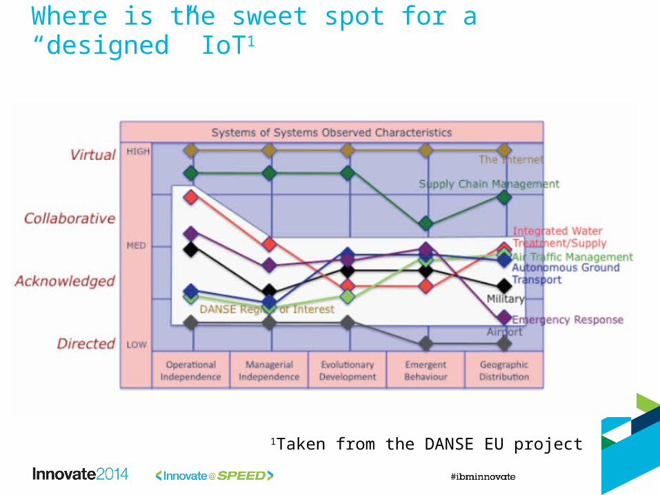
Where is the sweet spot for a “designed” IoT1
1Taken from the DANSE EU project

Design Infastructure for the Internet of Things
13

14
Continuous engineering - game-changing capabilities for systems design
• Continuous Verification“Measure twice, cut once”
continuously verify the emergent behavior of complex IoT systems
• Strategic Reuse“Don’t reinvent the wheel” Reusing cloud based services is key to efficient development of IoT systems and their quality
Unlocking Engineering Knowledge“Turn Insight into Outcomes”Access, understand all engineering information, regardless of source – to enable the right decisions at the right times
Continuous engineering is an enterprise capability that speeds delivery of increasingly complex and connected products by enabling engineers to accelerate learning throughout the lifecycle, while managing cost, quality and risk.
Continuous Engineering Practices are key to the design of complex systems such as those enabled by the Internet of Things

• Analyze, Architect, Optimize, Validate, and Generate complex systems software
Collaborative MBD with Rational Rhapsody
Continuous Validation
Test Automation
Trade Studies and
optimization
Domain Focused Modeling
SoS, SE, SwE
CollaborativeDesign
End to End Integration
Implementation Automation
“code generation”

Proposed IoT design flow
16
Service Design
Behavioral Analysis
Embedded SW design
Capability Analysis
DeviceIoT cloud
Automation of interface specs and data definitions (e.g. MQTT)
BehaviorSpecifications
IoT Architecture Framework (based on UPDM)
Service CatalogueBluemix services

Design objectives• Specifying and understanding the operation of the IoT architect
– Observe, Analyse, React : pattern for most smart systems– Develop high level understanding of IoT
• Synthesizing the architecture– Interfaces– Infrastructure components
• Optimizing architecture– MoEs, Objective functions– Optimization technology
• Understanding & Observing Emergent behavior– When Systems interact System of System show different properties
• Validating the solution: Simulation techniques for IoT– Agent Based Modelling– Continuous Modelling– Predictive analytics
• Automating the implementation– Generating interfaces and data definition for cloud services– Generating the device embedded application

Case Study: Autonomous Traffic Management Specification
18

Autonomous Traffic Management Case StudyScenarios•Trip Preparations•City traffic
– Interactions with other autonomous cars
– Interactions with pedestrians– Overtaking Situations
•Autonomous Parking•Public Driverless Taxi•PDL back to the airport•Private Car comes home•Billing
Needs a graphic of some sort

Autonomous Transportation System – key components• City Grid
– The city grid is the playground for the simulation upon which the different scenarios are to be run. It includes the models of the cars and pedestrians.
• Traffic Management– Maintains the overall traffic management – managing the traffic based on the density of cars over the
city districts. In addition it manages daytime dependent changes in the architecture of the city grid. It contains the local traffic management modules which optimise the traffic based on the global goal of shortest travel time over all participants within their district. Both traffic management parts will in separate Simulink modules. The linking of the control parts and the city grid will be done via a UPDM diagram
• Travel Management– The travel management is responsible for the planning of trips and the coordination of the chosen
modes of tranport. This includes coordinating both the use of private cars and public transports. The billing is done centralized after the trip has ended. The traffic management is not directly modelled. It influences the model through additional optimization and constraint goals.
• Autonomous Cars– Cars are controlled by the local traffic management modules but have emergency behaviour in case
the contact to the traffic management is interrupted. In such cases, they will need to behave without any routing information and infrastructure assistance, based on their own perception of the environment and direct communication with other traffic participants.
• Pedestrians– At a first step the pedestrians will cross the street without directly interacting with the autonomous
cars. The ‘intermediate’ pedestrian version will vary in his speed and waiting time according to studies. The last evolutionary step of the pedestrian model within this test case will include direct interaction between pedestrians and cars.

Methodology• Capability driven
– Consider operational aspects of the capabilities that need to be realised• High level what you want to do (very functional)
• Need to think service orientated– Services expose capabilities – Services act as an abstraction layer for different implementations– Drives reuse and keeps the “What“ separated from the “How”
• Provides a means to evolve the SoS
• Consider systems as platforms that use and provide services– Platforms as a service !
• Need to consider traceability across services and how they can be reused– Identifying reuse at a much higher level, fulfilling similar needs – MoEs are key here, captured as service levels.– MoEs heavily tied to infrastructure in this instance.
• Network considerations• Hardware considerations• Location and Environement
– MoEs drive the implementation of the IoT as they determine the “how”

Autonomous Transport Management
The reality of the situation, 380 Taxis over 24 hours

Mission and High level Specification
IoT Implementation Services
Simplified Architecture
Operational Analysis
Systems of Services
Application Services
Domain Services
Foundation Services

Autonomous Transportation:-Capability Views (CV-1/2)• Capability: ability to
achieve a desired affect• Capability Taxonomy
– Sets the context for the architecture
– Lets you think about what you are trying to achieve
– Can be used to capture reqs and desired effects (MoEs)
• Capability Dependencies– Widen the scope– Helps Identify
commonly used capabilities
• Reuse implementation
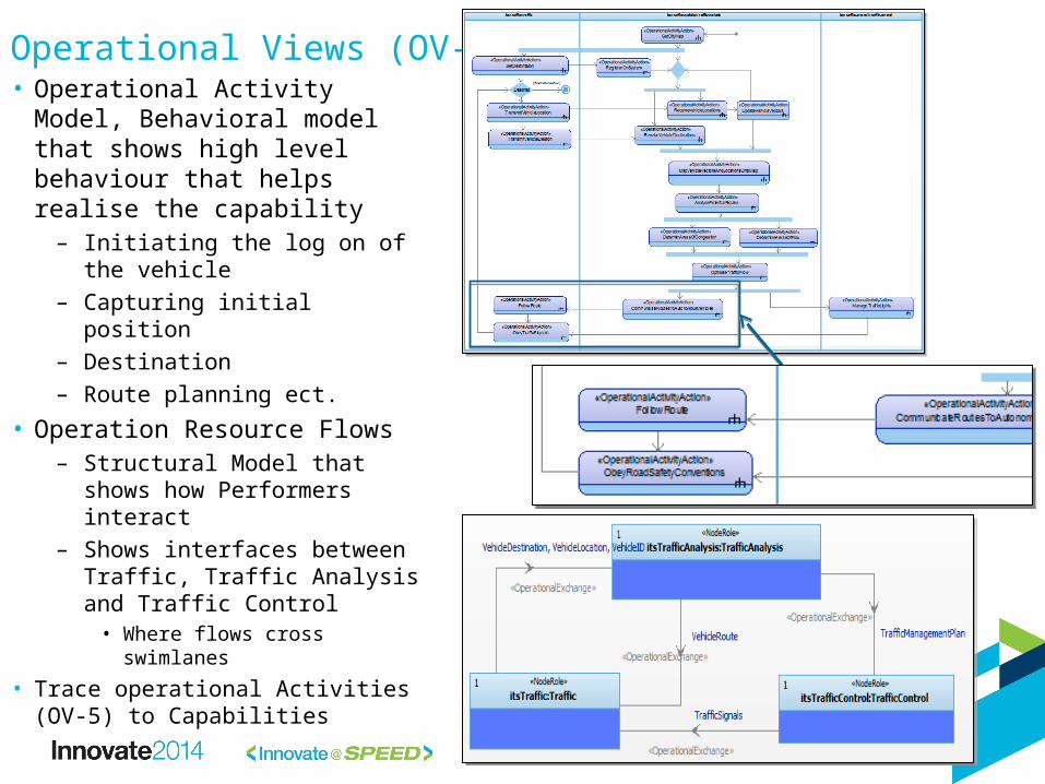
Operational Views (OV-5/2)• Operational Activity Model,
Behavioral model that shows high level behaviour that helps realise the capability– Initiating the log on of the
vehicle– Capturing initial position– Destination– Route planning ect.
• Operation Resource Flows– Structural Model that shows
how Performers interact– Shows interfaces between
Traffic, Traffic Analysis and Traffic Control
• Where flows cross swimlanes
• Trace operational Activities (OV-5) to Capabilities

System Behaviour (SV-4)• Putting more detail into the analysis
– Allocated to • Navigation• EngineControls• Traffic and PedestrianManagement• AutonomousRouteFollowing
– Traceability back to the higher level
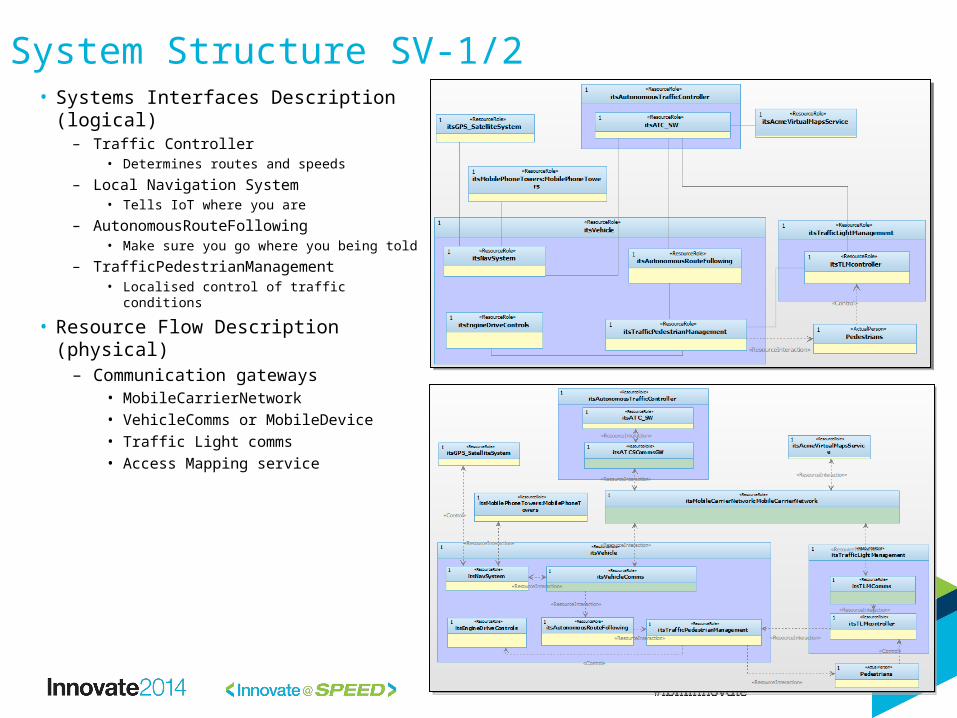
System Structure SV-1/2• Systems Interfaces Description
(logical)– Traffic Controller
• Determines routes and speeds– Local Navigation System
• Tells IoT where you are– AutonomousRouteFollowing
• Make sure you go where you being told– TrafficPedestrianManagement
• Localised control of traffic conditions
• Resource Flow Description (physical)– Communication gateways
• MobileCarrierNetwork• VehicleComms or MobileDevice• Traffic Light comms• Access Mapping service

Case-Study: Continuous Validation
28

Validating Behaviour• Need to ensure that IoT governance of “Things” does not lead to catastrophic results• Create Agent based simulation of part of the traffic flow scenario as an example
• Augmented the UPDM model with an Agent View expressed in SysML • Sub set of behaviour regarding the interaction of
– Autonomous Traffic Control system controlling maximum speed in an area– Individual parameters and control algorithms of vehicles– Interaction with pedestrians
• Takes an agent based approach
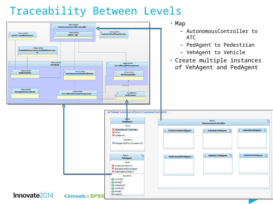
Traceability Between Levels• Map
– AutonomousController to ATC
– PedAgent to Pedestrian– VehAgent to Vehicle
• Create multiple instances of VehAgent and PedAgent
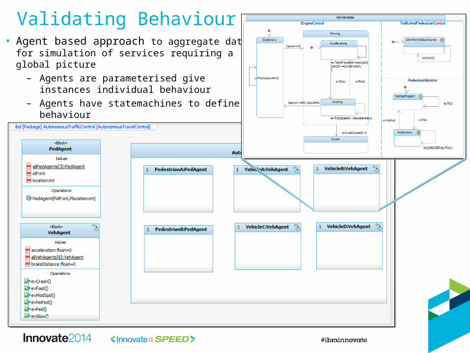
Validating Behaviour• Agent based approach to aggregate data for
simulation of services requiring a global picture– Agents are parameterised give instances
individual behaviour– Agents have statemachines to define
behaviour

Validating Behaviour• Global Autonomy
– IoT Autonomous controller controls max speed for a paricular street
• Already assumes sent out route coordinates to vehicles
• Local Autonomy– Vehicles know about vehicles in front, takes into braking effect– Vehicles also know pedestrians within a certain “safe braking”
range• When pedestrian detected vehicle brakes hard• If a vehicle goes past a pedestrian ! CRASH

Validating Behaviour• Run simulation showing
multiple vehicle agents
• Initial simulation shows crash with pedestrian can occur in Vehicle B

Continuous Engineering in Action… • Crash caused by factors outside of the control of IoT
– Braking constants for vehicles, Weather, Bad Tyres• Make Autonomous Controller “Smarter”
– Capture average speed of vehicles in area– If pedestrians detected then modify the maximum speed based upon a variation of the average
speed– SLOWS everything down in general area
• No Accident

Conclusion• IoT applications are essentially what Systems Engineering calls “Systems of Systems” – an area where
continuous engineering practices exist for quite some time– Emergent properties are more complex than we can currently perceive
• Need an enterprise/SoS approach to understand the true scope of emergent properties– Smart device will get smarter and we need to understand levels of autonomony
• Need to understand the evolution of devices and how they interact with legacy systems
• As such, in certain cases such IoT applications require a systems engineering approach, following continuous engineering principles
– Specify the functionality of the system in an operational context– Specify the MoEs for the IoT– Derive the system architecture and the required services– Validate the system before it is put into operation – Optimize parameters based on the MoEs
• We illustrated the validation of emergent behaviors using agent simulation approach– To identify unsafe situations– To optimize and analyze system MoEs
• Recommended future work– Specifying a profile with the necessary views to carry out IoT/SoS design– Develop a framework for IoT simulation following an agent simulation approach

Acknowledgements and Disclaimers
© Copyright IBM Corporation 2012. All rights reserved.– U.S. Government Users Restricted Rights - Use, duplication or disclosure restricted by GSA ADP Schedule Contract
with IBM Corp.
IBM, the IBM logo, ibm.com, Rational, and IBM Rational Rhapsody are trademarks or registered trademarks of International Business Machines Corporation in the United States, other countries, or both. If these and other IBM trademarked terms are marked on their first occurrence in this information with a trademark symbol (® or ™), these symbols indicate U.S. registered or common law trademarks owned by IBM at the time this information was published. Such trademarks may also be registered or common law trademarks in other countries. A current list of IBM trademarks is available on the Web at “Copyright and trademark information” at www.ibm.com/legal/copytrade.shtml
Mathworks, Matlab, Simulink, UPDM, SysML, UML, Modelica, Desrye, Plasma, Pheonix Integration, FMIOther company, product, or service names may be trademarks or service marks of others.
Availability. References in this presentation to IBM products, programs, or services do not imply that they will be available in all countries in which IBM operates.
The workshops, sessions and materials have been prepared by IBM or the session speakers and reflect their own views. They are provided for informational purposes only, and are neither intended to, nor shall have the effect of being, legal or other guidance or advice to any participant. While efforts were made to verify the completeness and accuracy of the information contained in this presentation, it is provided AS-IS without warranty of any kind, express or implied. IBM shall not be responsible for any damages arising out of the use of, or otherwise related to, this presentation or any other materials. Nothing contained in this presentation is intended to, nor shall have the effect of, creating any warranties or representations from IBM or its suppliers or licensors, or altering the terms and conditions of the applicable license agreement governing the use of IBM software.
All customer examples described are presented as illustrations of how those customers have used IBM products and the results they may have achieved. Actual environmental costs and performance characteristics may vary by customer. Nothing contained in these materials is intended to, nor shall have the effect of, stating or implying that any activities undertaken by you will result in any specific sales, revenue growth or other results.

Thank You!
Your Feedback is Important!
Access the Innovate agenda tool to complete your session surveys from your smartphone, laptop or
conference kiosk.