Symptom association probability and symptom sensitivity index ...

32DFL02.E 3 - 1
III. MAINTENANCE AND TROUBLESHOOTING egular maintenance of the Ricon Innovator Wheelchair Lift will reduce the frequency of repairs and contribute to optimum performance and safe operation. This chapter contains cleaning and lubrication instructions, a maintenance schedule, a troubleshooting section, plus hydraulic and electrical diagrams.
WARNING!
THIS RICON PRODUCT IS HIGHLY SPECIALIZED. MAINTENANCE AND REPAIRS MUST BE PERFORMED BY A RICON AUTHORIZED SERVICE TECHNICIAN USING RICON REPLACEMENT PARTS. MODIFYING OR FAILING TO PROPERLY MAINTAIN THIS PRODUCT WILL VOID THE WARRANTY, AND MAY RESULT IN UNSAFE OPERATING CONDITIONS. AFTER THE WARRANTY PERIOD, RICON RECOMMENDS THAT TROUBLESHOOTING BE CONTINUED BY A RICON AUTHORIZED SERVICE TECHNICIAN.
A. CLEANING Regular cleaning with mild soap and water (i.e. liquid dish soap or liquid car wash soap) and then drying thoroughly will protect painted lift surfaces. Cleaning the lift is especially important in areas of the country where roads are salted in winter or when dirt, mud, snow, etc. can be tracked into vehicle.
B. MAINTENANCE CHECKLIST Under normal operating conditions, maintenance inspections are required at least every six months (1750 cycles) and a thorough inspection should be performed as specified in Table 3-1. Service should be more frequent when the lift is used ten times per day, or more.
TABLE 3-1: MAINTENANCE CHECKLIST
SERVICE POINT ACTION TO PERFORM
Decals Refer to Figure 2-5. Verify that all lift decals are properly affixed, clearly visible, and legible. Replace if necessary.
Overall condition Inspect lift for damaged or missing parts.
Control pendant Check control pendant for damage and verify that its cable connections are secure.
Electrical wiring Inspect all accessible electrical wiring for damaged wires (cut, frayed, unsecured) and loose connectors.
Handrail Verify that handrail fasteners are properly tightened.
Lift mounting points
• Verify that the mounting hardware is secure and undamaged. • Verify that mounting bracket screws are properly tightened.
Main lifting pivots Check that all traveling frame pins are in place, free from damage, and locked in position.
• Check for hydraulic fluid leakage along all lines. • Check that backup pump manual release valve is lightly closed. • Check hydraulic cylinder for leaks. • Inspect hydraulic hoses for damage. • Verify that all fittings are tightly secured.
CAUTION
Add hydraulic fluid when platform is at ground level. Filling reservoir when platform is above ground level will result in overflow from reservoir when platform is lowered.
Hydraulic system
• Lower platform to ground level and check hydraulic fluid level. If level is below FULL mark, add Texaco 01554 Aircraft Hydraulic Oil, or equivalent fluid per U.S. Mil Spec H5606G.
R

32DFL02.E 3 - 2
TABLE 3-1: MAINTENANCE CHECKLIST
SERVICE POINT ACTION TO PERFORM
Operation • Operate lift through several full cycles (deploy, lower, raise, stow) using control pendant. Note unusual noises or movements.
• Deploy lift to floor level. Set Wrap Disable switch to on position and stow lift using control pendant. Platform must fold into vertical position and move into vehicle, but not wrap (Figure 1-3).
• Deploy lift to floor level. Set Wrap Disable switch to off position and stow lift using control pendant. Platform must fully fold and wrap into vehicle (Figure 1-4).
Handrail mounted control switch
• Verify switch moves platform from floor level to ground when held in Down position. • Verify switch moves platform from ground to floor level when held in Up position.
Platform rollstop Check for proper rollstop operation when platform contacts ground; side barriers and front rollstop must deploy (unfold) fully and lay flush against ground.
Manual operation 1) Manually unfold platform by using manual release T-handle as specified in Chapter III of the Operator Manual. Platform must unfold smoothly, with no binding or jamming.
2) Lower platform to vehicle floor level using manual backup pump release valve. Close release valve when platform reaches vehicle floor level. Platform must deploy smoothly, with no binding or hesitation.
3) With platform at floor level, attempt to lower (unfold) bridgeplate without pushing bridgeplate release lever. Bridgeplate must resist unfolding. Push bridgeplate release lever and deploy bridgeplate to its horizontal position. Check that bridgeplate moves into horizontal position. Raise and lock bridgeplate in vertical position.
4) Verify that side barriers and front rollstop resist deployment (unfolding) when not at ground level.
5) Verify that side barriers and front rollstop can be fully deployed (unfolded) manually when platform is at ground level.
6) Manually stow platform as specified in Chapter III of the Operator Manual. Platform must lock in place when T-handle is released.
Cleaning and lubrication
Clean exposed lift surfaces with mild soap and water; dry thoroughly. Inhibit rust by using a clean, soft cloth to apply a light film of oil to all surfaces. Remove excess oil.
END OF TABLE
C. TROUBLESHOOTING
1. TROUBLESHOOTING GUIDE The troubleshooting guide is intended to provide a logical starting point for general lift problems. However, not all possible problems or combinations of problems are listed. The guide assumes that the vehicle battery is fully charged and its connections are clean and tight.
WARNING!
THE TROUBLESHOOTING GUIDE DOES NOT INCORPORATE ROUTINE SAFETY PRECAUTIONS OR PRELIMINARY PROCEDURES. TROUBLESHOOTING MUST BE PERFORMED BY A TRAINED, AUTHORIZED RICON SERVICE TECHNICIAN DURING THE RICON WARRANTY PERIOD. IT IS RECOMMENDED THAT TROUBLESHOOTING ALSO BE PERFORMED BY AN AUTHORIZED RICON SERVICE TECHNICIAN AFTER THE WARRANTY PERIOD.

32DFL02.E 3 - 3
TABLE 3-2: TROUBLESHOOTING GUIDE
SYMPTOM POSSIBLE CAUSE REMEDY
Main Circuit Breaker (located in engine compartment) has tripped.
Reset circuit breaker.
Control System Circuit Breaker (located on lift tower) has tripped.
Reset circuit breaker.
Lift does not operate when Deploy button is pressed
Faulty lift power wiring. Repair wiring.
Safety interlock not engaged. Engage safety interlock.
Control pendant Stow–Deploy switch is defective (deploy contacts open).
Replace stow/deploy switch.
Lift wrap motor is defective. Replace motor.
Controller unwrap circuit is defective. Replace controller.
Lift does not operate when Deploy button is pressed; circuit breakers have not tripped
Loose or faulty wiring. Repair wiring.
Down Valve is defective. Replace down valve.
Controller down valve circuit is defective. Replace controller.
Lift unwraps but does not unfold when Deploy button is pressed
Loose or faulty wiring. Repair wiring.
Platform folding linkage (connected to fold bracket) requires adjustment.
Adjust linkage rod ends. Platform does not unfold or fold completely
Debris between folding platform cam follower and track (part of platform folding bracket).
Clean cam follower and track.
Platform Unwrapped limit switch is defective (contacts open) or out of adjustment.
Replace switch.
Faulty Platform Unwrapped limit switch wiring. Repair wiring.
Wrap motor continues to run when platform is fully unwrapped
Controller platform wrapping circuit is defective. Replace controller.
Control pendant Up–Down switch is defective (down contacts shorted).
Replace switch.
Handrail-mounted control switch is defective (down contacts shorted).
Replace switch.
Lift moves down automatically from floor
Faulty pendant or control switch wiring. Repair wiring.
Platform Above Floor limit switch is defective or out of adjustment.
Repair or adjust switch.
Platform Below Floor limit switch is defective or out of adjustment.
Repair or adjust switch.
Platform stops above or below vehicle floor level when Deploy button is pressed
Loose or faulty floor level switch wiring. Repair wiring.

32DFL02.E 3 - 4
TABLE 3-2: TROUBLESHOOTING GUIDE
SYMPTOM POSSIBLE CAUSE REMEDY
Hydraulic pump motor is defective. Replace motor.
Front and rear platform contacts are dirty or do not touch.
Clean or adjust platform contacts.
Rollstop and Barrier Up limit switch is defective (left or right side) or out of adjustment.
Repair or adjust switch.
Side Barrier Locked limit switch (left or right side) is defective or out of adjustment.
Repair or adjust switch.
Loose or faulty wiring. Repair wiring
Controller pump circuit is defective. Replace controller.
Control pendant Up–Down switch is defective (up contacts open).
Replace control pendant.
Handrail-mounted control switch is defective (up contacts open).
Replace control switch.
Up function inoperative; pump motor does not operate
Pump motor solenoid is open Replace solenoid.
Platform overloaded. Load must not exceed 660 lbs (300 kg).
Backup pump manual release valve open. Close valve lightly, taking care not to over-tighten.
Hydraulic fluid level low. Check fluid level; add fluid as necessary.
Down valve open. Replace down valve.
Air in hydraulic system. Cycle lift several times or bleed system.
Up function inoperative; pump motor operates
Leak in hydraulic system. Check lines and fittings; repair or tighten as necessary.
Bridgeplate motor is defective. Replace motor.
Platform Above Floor or Platform Below Floor limit switches are defective or out of adjustment.
Repair or adjust switches.
Controller bridgeplate circuit is defective. Replace controller.
Bridgeplate mechanism is jammed or defective. Repair or replace bridgeplate mechanism.
Bridgeplate does not stow or does not deploy
Loose or faulty bridgeplate motor wiring. Repair wiring.

32DFL02.E 3 - 5
TABLE 3-2: TROUBLESHOOTING GUIDE
SYMPTOM POSSIBLE CAUSE REMEDY
Rollstop motor is defective. Replace rollstop motor.
Platform On Ground limit switch is defective or out of adjustment.
Repair or adjust switch.
Rollstop mechanical linkage is defective. Repair rollstop linkage.
Controller rollstop lowering circuit is defective. Replace controller.
Rollstop does not open
Loose or faulty rollstop motor wiring. Repair wiring.
Rollstop motor is defective. Replace motor.
Controller rollstop circuit is defective. Replace controller.
Rollstop mechanical linkage is defective. Repair rollstop linkage.
Rollstop does not close
Loose or faulty rollstop motor wiring. Repair wiring.
Rollstop does not latch
Debris in latch mechanism (part of actuator shoe assy).
Remove debris.
Lift operates with rollstop open
Rollstop and Barrier Up limit switches (left or right side), is defective or out of adjustment.
Repair or adjust switch.
Rollstop opens at any lift position
Platform On Ground limit switch, is defective or out of adjustment.
Repair or adjust switch.
Control pendant Up–Down switch is defective (up contacts shorted) or handrail-mounted control switch is defective (up contacts shorted).
Replace switch. Lift moves up automatically from ground
Control pendant or control switch faulty wiring. Repair wiring.
Platform stops above floor level when Up button is pressed
Platform Below Floor limit switch is defective or out of adjustment.
Repair or adjust switch.
Pump solenoids chatter
Poor electrical connection between negative bus bar, pump block, or solenoid plate.
Tighten or clean connections.
Fold Cutoff limit switch is defective or out of adjustment.
Repair switch or wiring.
Control pendant Stow–Deploy switch is defective (stow contacts open).
Replace switch wiring.
Platform Pressure Switch is defective. Replace pressure switch.
Lift will not stow
Loose or faulty wiring. Repair wiring.
Control pendant Stow–Deploy switch is defective (stow contacts shorted).
Replace switch. Lift stows automatically when at floor level or above
Faulty control pendant wiring. Repair wiring.

32DFL02.E 3 - 6
TABLE 3-2: TROUBLESHOOTING GUIDE
SYMPTOM POSSIBLE CAUSE REMEDY
Fold Cutoff limit switch is defective or out of adjustment.
Repair switch or wiring.
Faulty Fold Cutoff limit switch wiring. Repair wiring.
Pump motor runs after lift is stowed
Controller Fold Cutoff circuit is defective. Replace controller.
Platform Wrapped limit switch is defective or out of adjustment.
Repair switch or wiring.
Controller platform wrapping circuit is defective. Replace controller.
Wrap motor runs after lift is stowed
Loose or faulty wiring. Repair wiring.
Wrap Disable switch set to ON. Set Wrap Disable switch to OFF.
Platform folds into vehicle but does not wrap when Stow button is pressed Wrap Disable switch, or its wiring, faulty. Repair switch or wiring.
Platforms fully wraps into vehicle with Wrap Disable switch set to ON
Wrap Disable switch, or its wiring, faulty. Replace switch.
Power door operator circuit breaker (located on lift tower) is tripped.
Reset circuit breaker.
Left power door operator motor is defective. Replace power door operator.
Loose or faulty wiring. Repair wiring.
Power door operator mechanical linkage is defective. Repair door operator linkage.
Power door operators do not open vehicle doors
Controller vehicle door operator circuit is defective. Replace controller.
Power door operator mechanical linkage is defective. Repair door operator linkage.
Loose or faulty wiring. Repair wiring.
Platform Wrapped limit switch is defective or out of adjustment.
Repair switch or wiring.
Power door operators do not close vehicle doors
Controller vehicle door operator circuit is defective. Replace controller.
END OF TABLE

32DFL02.E 3 - 7
2. ELECTRICAL SYSTEM DIAGNOSTIC DISPLAYS Observe the LED display on the main controller board (located at the lower front of the tower) to monitor electrical events that occur in the lift. These lights provide an indication of what the lift status is, such as the position of components (rollstop up, platform wrapped, platform below floor level, etc), or occurrence of output signals that energize electrical components (hydraulic pump, rollstop motor, etc), or the need for precaution (high current in certain circuits, vehicle door open, etc). Refer to Figure 3-1 and Table 3-3 on the following pages for the location of each light and a description of what each light indicates. Refer to Tables 3-4 through 3-8 on the following pages. Also located on the main controller board is a numerical LED display that is useful for troubleshooting electrical problems. Each platform motion (deploy, lower, raise, stow) can be divided into a series of steps, and one or more events occur during that step. Each event has input and output signals associated with it. If a problem occurs during one of those steps, a number representing the step will be shown on the display. Table 3-4 describes the main controller’s numerical display. Tables 3-5 through 3-8 describe each platform motion. When one of the motions begins, all of the numbers listed at the top of the appropriate platform motion table will quickly flash in sequence. If a problem occurs during that motion, the number for the faulty step will be displayed continuously. Refer to the table column below the number displayed for the events that occur during that step. The problem could be caused by one of the controllers, an input signal switch, an output component (motor, valve, etc), or the related wiring and connectors. Each platform motion table is formatted to reflect lift operation. The table has a status number at the top of a column with a list of input switches, controller commands, and output relays. The state of each input and output is specified for a given step. If the state is specified as ON, then the switch must be closed, the controller command must be active, or the output relay coil must be energized during that step. If the state is specified as OFF, then the switch must be open, the controller command must be inactive, or the output relay coil must be de-energized (no power applied). A blank space means that the input or output is ignored during that step.

32DFL02.E 3 - 8
FIG
UR
E 3
-1:
MA
IN C
ON
TR
OL
LE
R D
IAG
NO
ST
IC L
ED
LA
YO
UT

32DFL02.E 3 - 9
TABLE 3-3: DIAGNOSTIC LED DISPLAY GUIDE LED LABEL DESCRIPTION
Bridgeplate is down On when bridgeplate is fully lowered.
Bridgeplate is up On when bridgeplate is fully folded (perpendicular to platform).
Close vehicle doors On when controller sends a close signal to door operators.
Com 1 circuit is shorted On when a high-current condition occurs in COM1 circuit.
Com 2 circuit is shorted On when a high-current condition occurs in COM2 circuit.
Communications failure On if remote controller does not respond to commands from main controller.
Deploy signal On when Deploy button is pressed on control pendant.
Down signal On when Down button is pressed on control pendant.
Lower bridgeplate On when controller sends a lower signal to bridgeplate motor.
Lower rollstop On when controller sends a lower signal to left and right rollstop motors.
Lift status Counter display provides lift status number.
Open down valve On when controller energizes the down valve.
Open vehicle doors On when controller sends an open signal to power door operators.
Platform-below-floor warning
On when platform is lower than floor level; 12VDC will be available at pin 5 of P2.
Platform is above floor level
On when platform is higher than floor level.
Platform is below floor level
On when platform is lower than floor level.
Platform is folded On when platform is fully folded.
Platform is on ground On when platform has fully settled on ground.
Platform is unwrapped On when the platform is fully folded but not wrapped.
Platform is wrapped On when platform is fully folded and wrapped.
Platform occupied On when there is no weight present on platform; off when 50 lbs, or more, is present.
Processor status Blinks when controller microprocessor is operating normally.
Raise bridgeplate On when controller sends a raise signal to bridgeplate motor.
Raise rollstop On when controller sends a raise signal to left and right rollstop motors.
Remote error On if main controller receives a communications error signal from remote controller (commands not accepted).
Rollstop is up On when both front rollstops are raised.
Side barriers are locked On when both side barriers are raised and locked.
Stow signal On when Stow button is pressed on the control pendant.
Turn hydraulic pump on On when controller energizes hydraulic pump solenoids.
Unwrap platform On when controller sends an unwrap signal to the platform wrap motor.
Up signal On when Up button is pressed on the control pendant.
Vehicle doors are open On when power door operator (if installed) detects that vehicle doors adjacent to lift are open, indicating that lift can be deployed. This light is on continuously when the power door operator jumper is connected to J5.
Vehicle engine is running On when vehicle engine speed is at idle, or higher.

32DFL02.E 3 - 10
TABLE 3-3: DIAGNOSTIC LED DISPLAY GUIDE LED LABEL DESCRIPTION
Wrap enable On when wrap disable switch is off. When switch is off, the platform wraps normally.
Wrap platform On when controller sends a wrap signal to the platform wrap motor.
TABLE 3-4: NUMERICAL DISPLAY DESCRIPTIONS STATUS NUMBER FUNCTION LIFT CONDITION
00 None selected
Default display; control pendant and handrail control switch are not in use. Platform is at rest in any position.
05 UP Platform on ground; rollstops in transition (moving from horizontal to vertical position).
07 UP Front platform assembly not in contact with ground; rear platform assembly still in contact with ground.
10 UP Platform off ground and moving up to vehicle floor level.
15 UP Platform at vehicle floor level; bridgeplate moving from vertical to horizontal position.
20 UP Platform at vehicle floor level; bridgeplate is in horizontal position.
26 DOWN Platform in motion from vehicle floor level to ground level.
30 DOWN Rear platform assembly in contact with ground; front platform assembly settling to ground level.
35 DOWN Platform is on ground; rollstops are down (horizontal).
50 DEPLOY Displayed only if vehicle door operators are installed. Platform is fully wrapped; Open Door command sent to vehicle door operators.
60 DEPLOY Platform in motion from fully wrapped to fully unwrapped position.
62 DEPLOY Platform fully unwrapped and still in vertical position.
65 DEPLOY Platform unfolding from vertical to horizontal position.
70 DEPLOY Platform at vehicle floor level.
75 STOW Error message; displayed only when platform is at floor level and there is no communication between front and rear platform assemblies (contact switch assembly is open).
76 STOW Error message; displayed only when platform is below vehicle floor level and there is no communication between front and rear platform assemblies (contact switch assembly is open).
77 STOW Platform in motion from floor level to vertical position.
78 STOW Platform in vertical position and is unwrapped.
80 STOW Platform in motion from fully unwrapped to fully wrapped position.
82 STOW Platform fully wrapped.
85 STOW Platform fully wrapped. Close Door command sent to door operators (if installed).

32DFL02.E 3 - 11
TABLE 3-5: DISPLAY NUMBER DESCRIPTIONS FOR DEPLOY MOTION
STATUS NUMBER 50 (SEE NOTE 5)
60 62 65 70
INPUT SWITCHES (SEE NOTE 4) GROUND CONTACT
ROLLSTOP IS UP ON ON ON ON PLATFORM IS WRAPPED
(SEE NOTE 1) ON
PLATFORM IS UNWRAPPED ON ON ON BRIDGEPLATE IS DOWN ON
BRIDGEPLATE IS UP ROLLSTOP IS LOCKED ON ON ON ON
REMOTE ERROR PLATFORM OCCUPIED ON ON
VEHICLE DOORS ARE OPEN (SEE NOTE 6) ON ON ON ON ON
PLATFORM BELOW FLOOR LEVEL PLATFORM ABOVE FLOOR LEVEL ON ON ON OFF
PLATFORM IS FOLDED ON ON WRAP ENABLE (SEE NOTE 2) ON ON ON ON
CONTROLLER COMMANDS (SEE NOTES 3 AND 4) CLOSE DOORS OPEN DOORS ON
LOWER ROLLSTOP RAISE ROLLSTOP
LOWER BRIDGEPLATE RAISE BRIDGEPLATE UNWRAP PLATFORM ON ON
WRAP PLATFORM OFF
OUTPUT RELAYS (SEE NOTE 4) OPEN DOWN VALVE ON OFF
HYDRAULIC PUMP ON CLOSE DOORS OPEN DOORS ON ON ON ON ON
BELOW FLOOR ALARM SPEED ON
NOTES:
1. Lit momentarily at beginning of sequence if platform is fully wrapped. 2. Lit continuously when WRAP DISABLE switch is in the OFF (wrap enabled) position. 3. Command LEDs illuminate only while controller sends command to lift and are off at all other times. 4. When marked ON: switch must be closed, controller command must be active, or relay must be energized.
When marked OFF: switch must be open, controller must not issue command, or relay must not be energized. Blank: Don’t care.
5. Displayed only when power door operators are installed. 6. Lit continuously when the power door operator jumper is connected to J5.

32DFL02.E 3 - 12
TABLE 3-6: DISPLAY NUMBER DESCRIPTIONS FOR DOWN MOTION
STATUS NUMBER 25 26 30 35
INPUT SWITCHES (SEE NOTE 3) GROUND CONTACT ON
ROLLSTOP IS UP ON ON OFF PLATFORM IS WRAPPED
PLATFORM IS UNWRAPPED ON ON ON BRIDGEPLATE IS DOWN
BRIDGEPLATE IS UP ON ON ROLLSTOP IS LOCKED ON ON OFF
REMOTE ERROR PLATFORM OCCUPIED ON ON ON
VEHICLE DOORS ARE OPEN (SEE NOTE 4) ON ON ON
PLATFORM BELOW FLOOR LEVEL ON ON PLATFORM ABOVE FLOOR LEVEL OFF
PLATFORM IS FOLDED WRAP ENABLE (SEE NOTE 1) ON ON ON
CONTROLLER COMMANDS (SEE NOTES 2 AND 3) CLOSE DOORS OPEN DOORS
LOWER ROLLSTOP ON RAISE ROLLSTOP
LOWER BRIDGEPLATE RAISE BRIDGEPLATE ON UNWRAP PLATFORM
WRAP PLATFORM
OUTPUT RELAYS (SEE NOTE 3) OPEN DOWN VALVE ON ON OFF
HYDRAULIC PUMP ON CLOSE DOORS OPEN DOORS
BELOW FLOOR ALARM ON ON SPEED ON ON ON
NOTES:
1. Lit continuously when WRAP DISABLE switch is in the OFF (wrap enabled) position. 2. Command LEDs illuminate only while controller sends command to lift and are off at all other times. 3. When marked ON: switch must be closed, controller command must be active, or relay must be energized.
When marked OFF: switch must be open, controller must not issue command, or relay must not be energized. Blank: Don’t care.
4. Lit continuously when the power door operator jumper is connected to J5.

32DFL02.E 3 - 13
TABLE 3-7: DISPLAY NUMBER DESCRIPTIONS FOR UP MOTION
STATUS NUMBER 05 07 10 15 20
INPUT SWITCHES (SEE NOTE 3) GROUND CONTACT ON OFF
ROLLSTOP IS UP ON ON ON ON PLATFORM IS WRAPPED
PLATFORM IS UNWRAPPED ON ON ON ON ON BRIDGEPLATE IS DOWN ON
BRIDGEPLATE IS UP ON ON ON ROLLSTOP IS LOCKED ON ON ON
REMOTE ERROR PLATFORM OCCUPIED ON ON ON ON
VEHICLE DOORS ARE OPEN (SEE NOTE 4) ON ON ON ON ON
PLATFORM IS BELOW FLOOR LEVEL ON ON ON OFF
PLATFORM IS ABOVE FLOOR LEVEL OFF
PLATFORM IS FOLDED WRAP ENABLE (SEE NOTE 1) ON ON ON ON ON
CONTROLLER COMMANDS (SEE NOTES 2 AND 3) CLOSE DOORS OPEN DOORS
LOWER ROLLSTOP RAISE ROLLSTOP ON ON
LOWER BRIDGEPLATE ON RAISE BRIDGEPLATE UNWRAP PLATFORM
WRAP PLATFORM
OUTPUT RELAYS (SEE NOTE 3) OPEN DOWN VALVE
HYDRAULIC PUMP ON ON ON CLOSE DOORS OPEN DOORS
BELOW FLOOR ALARM ON ON ON SPEED ON ON ON ON ON
NOTES:
1. Lit continuously when WRAP DISABLE switch is in the OFF (wrap enabled) position. 2. Command LEDs illuminate only while controller sends command to lift and are off at all other times. 3. When marked ON: switch must be closed, controller command must be active, or relay must be energized.
When marked OFF: switch must be open, controller must not issue command, or relay must not be energized. Blank: Don’t care.
4. Lit continuously when the power door operator jumper is connected to J5.
32DFL02.E 3 - 14
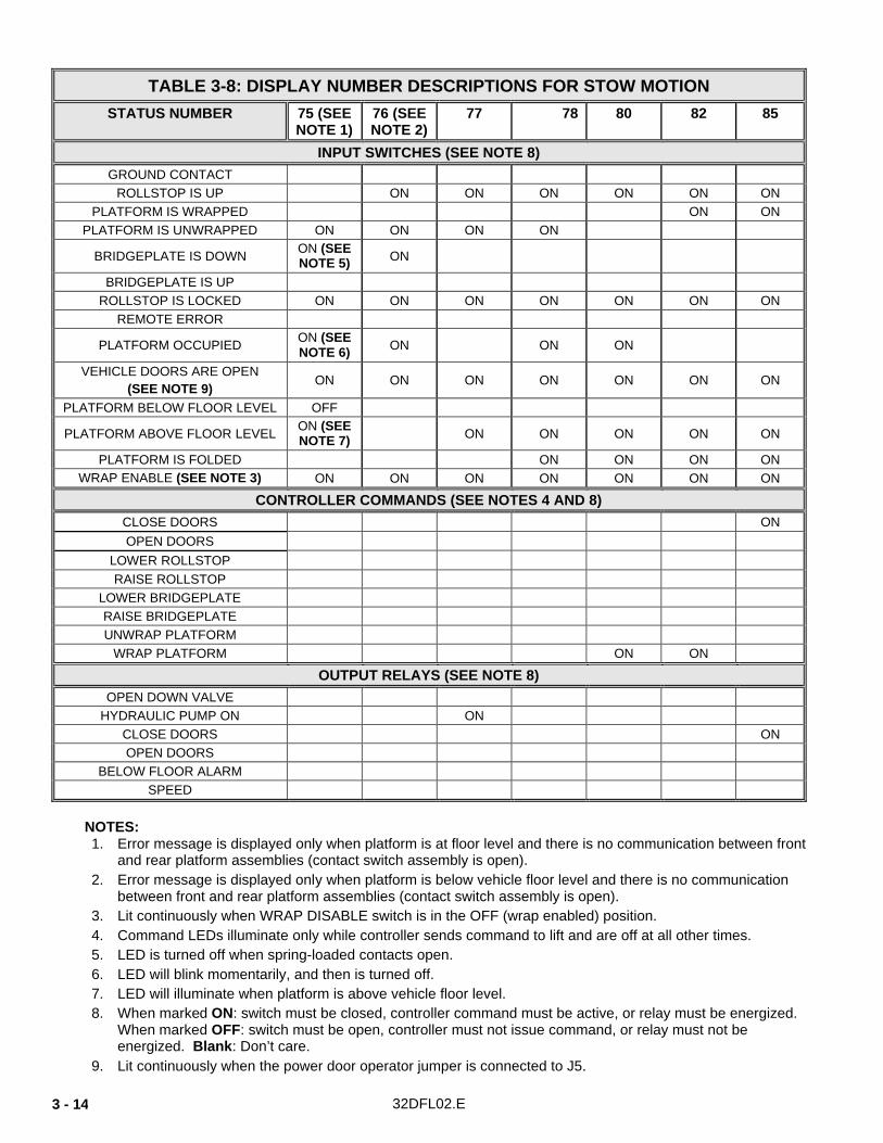
TABLE 3-8: DISPLAY NUMBER DESCRIPTIONS FOR STOW MOTION
STATUS NUMBER 75 (SEE NOTE 1)
76 (SEE NOTE 2)
77 78 80 82 85
INPUT SWITCHES (SEE NOTE 8) GROUND CONTACT
ROLLSTOP IS UP ON ON ON ON ON ON PLATFORM IS WRAPPED ON ON
PLATFORM IS UNWRAPPED ON ON ON ON
BRIDGEPLATE IS DOWN ON (SEE NOTE 5) ON
BRIDGEPLATE IS UP ROLLSTOP IS LOCKED ON ON ON ON ON ON ON
REMOTE ERROR
PLATFORM OCCUPIED ON (SEE NOTE 6) ON ON ON
VEHICLE DOORS ARE OPEN (SEE NOTE 9)
ON ON ON ON ON ON ON
PLATFORM BELOW FLOOR LEVEL OFF
PLATFORM ABOVE FLOOR LEVEL ON (SEE NOTE 7) ON ON ON ON ON
PLATFORM IS FOLDED ON ON ON ON WRAP ENABLE (SEE NOTE 3) ON ON ON ON ON ON ON
CONTROLLER COMMANDS (SEE NOTES 4 AND 8) CLOSE DOORS ON OPEN DOORS
LOWER ROLLSTOP RAISE ROLLSTOP
LOWER BRIDGEPLATE RAISE BRIDGEPLATE UNWRAP PLATFORM
WRAP PLATFORM ON ON
OUTPUT RELAYS (SEE NOTE 8) OPEN DOWN VALVE
HYDRAULIC PUMP ON ON CLOSE DOORS ON OPEN DOORS
BELOW FLOOR ALARM SPEED
NOTES: 1. Error message is displayed only when platform is at floor level and there is no communication between front
and rear platform assemblies (contact switch assembly is open). 2. Error message is displayed only when platform is below vehicle floor level and there is no communication
between front and rear platform assemblies (contact switch assembly is open). 3. Lit continuously when WRAP DISABLE switch is in the OFF (wrap enabled) position. 4. Command LEDs illuminate only while controller sends command to lift and are off at all other times. 5. LED is turned off when spring-loaded contacts open. 6. LED will blink momentarily, and then is turned off. 7. LED will illuminate when platform is above vehicle floor level. 8. When marked ON: switch must be closed, controller command must be active, or relay must be energized.
When marked OFF: switch must be open, controller must not issue command, or relay must not be energized. Blank: Don’t care.
9. Lit continuously when the power door operator jumper is connected to J5.

32DFL02.E 3 - 15
HYDRAULIC SYSTEM
FIGURE 3-2: HYDRAULIC SYSTEM

32DFL02.E 3 - 16
D. LIFT ELECTRICAL WIRING
1. DIAGRAM LEGENDS
a. Wire Color Codes
TABLE 3-4: WIRE COLOR CODES LETTER COLOR LETTER COLOR
BLK Black RED Red
BLU Blue WHT White
BRN Brown YEL Yellow
GRN Green YEL/BLK Yellow w/ black stripe
VIO Violet ORG Orange
WHT/ORG White w/ orange stripe GRY Grey
GRN/BLK Green w/ black stripe
END OF TABLE
b. Electrical Symbols
-
-
-
(P) (J)
FIGURE 3-3: ELECTRICAL SYMBOLS

32DFL02.E 3 - 17
2. ELECTRICAL CONNECTORS Refer to Figure 3-4 for standard pin arrangements of several plugs and receptacles used in the lift electrical wiring. Note that receptacles are designated on the electrical diagram with the letter J, and plugs with the letter P.
3. WIRING DIAGRAM LABELS
TABLE 3-5: WIRING DIAGRAM LABEL DEFINITIONS
LABEL DESCRIPTION
+12 VDC System operating voltage.
BRIDGEPLATE Electric motor; raises and lowers bridgeplate.
BRIDGEPLATE DOWN Limit switch; closes when bridgeplate is lowered (horizontal).
BRIDGEPLATE UP Limit switch; closes when bridgeplate is fully stowed (perpendicular to platform).
CLOSE VEHICLE DOOR Signal; from controller to power door operator; closes doors adjacent to lift.
CONTROL PENDANT Hand-held device; controls platform motions of deploy, stow, up, and down.
DEPLOY SIGNAL Signal; from control pendant; unfolds platform and lowers it to floor height.
DOWN SIGNAL Signal; from control pendant or handrail switch; lowers platform from any height.
DOWN VALVE Signal; from controller; opens down valve.
FOLD CUTOFF Limit switch; closes when platform is fully folded.
GROUND Common point for electrical system.
HYDRAULIC PUMP Electric motor; coupled to hydraulic pump.
HYDRAULIC PUMP SOLENOIDS
Signal; from controller to pump solenoids; solenoids provide current to hydraulic pump motor.
LEFT ROLLSTOP Electric motor; raises and lowers left side barrier and left front rollstop.
LEFT SIDE BARRIER LOCKED Limit switch; closes when barrier on left side is upright and locked.
LEFT SIDE ROLLSTOP AND BARRIER UP
Limit switch; closes when rollstop is fully raised (upright).
MAIN CONTROLLER Electronic component; located in base of tower; controls lift functions and processes inputs from limit switches. Linked to remote controller by data bus.
FIGURE 3-4: PIN ARRANGEMENTS FOR ELECTRICAL CONNECTORS

32DFL02.E 3 - 18
TABLE 3-5: WIRING DIAGRAM LABEL DEFINITIONS
LABEL DESCRIPTION
OPEN VEHICLE DOOR Signal; from controller to power door operator; opens doors adjacent to lift.
PLATFORM ALARM Signal; +12 VDC 1A output available to vehicle for passenger warning.
PLATFORM OCCUPIED Pressure switch; opens when platform is loaded with 50 lbs or more.
PLATFORM ON GROUND Limit switch; closes when platform contacts ground.
PLATFORM UNWRAPPED Limit switch; closes when platform is fully unwrapped (Figure 1-3).
PLATFORM UP-DOWN Toggle switch; mounted on handrail; raises or lowers platform.
PLATFORM WRAP Electric motor; unwraps or wraps platform.
PLATFORM WRAPPED Limit switch; closes when platform is fully wrapped in stow position.
POWER DOOR OPERATOR JUMPER
Connector; installed in absence of power door operator; enables deploy function.
REMOTE CONTROLLER Electronic component; located on bottom side of platform; controls lift functions and processes inputs from limit switches. Linked to main controller by data bus.
RIGHT ROLLSTOP Electric motor; raises and lowers right side barrier and right front rollstop.
RIGHT SIDE BARRIER LOCKED
Limit switch; closes when barrier on right side is upright and locked.
RIGHT SIDE ROLLSTOP AND BARRIER UP
Limit switch; closes when rollstop is fully raised (upright).
RX+, RX-, TX+, and TX- Signals; data bus signals transfer data between main and remote controllers.
STOW SIGNAL Signal; from control pendant; raises platform and folds it into vehicle.
UP SIGNAL Signal; from control pendant or handrail switch; raises platform from any height.
VEHICLE DOORS ARE OPEN Signal; from power door operator; enables deploy function.
WRAP DISABLE Control switch; user operated to prevent platform from wrapping after it has been folded.
END OF TABLE
4. WIRING DIAGRAMS
Refer to Figures 3-5 and 3-6 on the following pages.

32DFL02.E 3 - 19
This page intentionally left blank.

32DFL02.E 3 - 20
FIGURE 3-5: INNOVATOR ELECTRICAL WIRING (SHEET 1 OF 2)

32DFL02.E 3 - 21
FIGURE 3-6: INNOVATOR ELECTRICAL WIRING (SHEET 2 OF 2)

32DFL02.E 3 - 22
This page intentionally left blank.
-GO TO NEXT CHAPTER- -BACK TO TABLE OF CONTENTS-