III 1 1 - International Society for Photogrammetry and ...€¦ · There are data from tacheometric...
10
DTH GENERATION FROM DIGITAL CONTOUR DATA USING ASPECT INFORMATION 1 .. Introduction K.. Inaba Geographical Survey Institute Ministry of Construction Kitazato-l, Yatabe-Machi Tsukuba-Gun, Ibaraki-Ken 305 Japan G. Aumann and HeEbner Chair for Photogrammetry Technical University of Munich ArcisstraBe 21, D 8000 Munchen 2 Federal Republic of Germany Commission III During the last thirty years Digital Terrain Models (DTMs) are subject of research, development and practical application (Miller and Laflamme, 1958) .. Nowadays DTMs are used for many different tasks and countrywide DTMs are generated.. At the Technical University of Munich DTMs are part of the research work for about ten years .. As generally agreed, a ·DTM is understood as a description of a terrain surface by digital data.. The as referred to in this paper, is a raster consisting of square grid meshes. The heights of the grid points are interpolated from the heights of given reference points. It is possible to generate DTMs from different input data. There are data from tacheometric survey, photogrammetric stereo measurement or from digitization of contour lines. The quality of the DTM highly depends on the input information. In this paper we deal with contour lines as input data for DTM generation. Using contour lines some specific problems appear. The data may be touched up cartographically already and important geomorphological information, like breaklines and skeleton lines usually do not exist explicitelly.. They are shown, however, implicitly-through the form of the contours. The conventional method of DTM generation from contour lines uses only the points, considering contour lines as random data. As mentioned above, not only the heights of points can be read from contours, but also geomorphological information.. Such information can be derived from the direction of steepest slope, or 'aspect' along the contour lines. Accordingly, the presented paper deals withDTM generation from digital contours using aspect information.. The capability of this method is checked by numerical calculations. The research work was started during a stay of the first author at the Chair for Photogrammetry of the Technical University of Munich as a guest scientist and was finished after his return to the Geographical Survey Institute, Tsukuba, Japan. III .... 1 1
Transcript of III 1 1 - International Society for Photogrammetry and ...€¦ · There are data from tacheometric...
DTH GENERATION FROM DIGITAL CONTOUR DATA USING ASPECT INFORMATION
1 .. Introduction
K.. Inaba Geographical Survey Institute Ministry of Construction Kitazato-l, Yatabe-Machi Tsukuba-Gun, Ibaraki-Ken 305 Japan
G. Aumann and HeEbner Chair for Photogrammetry Technical University of Munich ArcisstraBe 21, D 8000 Munchen 2 Federal Republic of Germany
Commission III
During the last thirty years Digital Terrain Models (DTMs) are subject of research, development and practical application (Miller and Laflamme, 1958) .. Nowadays DTMs are used for many different tasks and countrywide DTMs are generated.. At the Technical University of Munich DTMs are part of the research work for about ten years .. As generally agreed, a ·DTM is understood as a description of a terrain surface by digital data.. The as referred to in this paper, is a raster consisting of square grid meshes. The heights of the grid points are interpolated from the heights of given reference points. It is possible to generate DTMs from different input data. There are data from tacheometric survey, photogrammetric stereo measurement or from digitization of contour lines. The quality of the DTM highly depends on the input information. In this paper we deal with contour lines as input data for DTM generation. Using contour lines some specific problems appear. The data may be touched up cartographically already and important geomorphological information, like breaklines and skeleton lines usually do not exist explicitelly.. They are shown, however, implicitly-through the form of the contours. The conventional method of DTM generation from contour lines uses only the points, considering contour lines as random data. As mentioned above, not only the heights of points can be read from contours, but also geomorphological information.. Such information can be derived from the direction of steepest slope, or 'aspect' along the contour lines. Accordingly, the presented paper deals withDTM generation from digital contours using aspect information.. The capability of this method is checked by numerical calculations. The research work was started during a stay of the first author at the Chair for Photogrammetry of the Technical University of Munich as a guest scientist and was finished after his return to the Geographical Survey Institute, Tsukuba, Japan.
III .... 1 1

2 .. Basic Idea
At the starting point we have digitized contours, which means, that we have points on the contour lines and the heights of these points. since our aim is to generate grid DTM, we need the heights of points between the ·contour lines .. When a human being tries to find the height of point P in figure 1, he will use two neighbouring contour lines of P. Estimating the line of steepest .slope passing P, he finds the intersections with the two neighbouring contour lines (points A and B) and can estimate the height at P from the heights at A and B, e.g .. by linear interpolation. Doing this he makes use of the fact that the direction of steepest slope or aspect is perpendicular to the contours.
Figure 1: Human interpolation process
The basic idea of DTM generation from contours presented in this paper is similar to this procedure.. First, the aspect on the contour lines is computed. Then the aspect at the grid points is interpolated from these data.. Finally, the DTM is generated using the aspect information.
3. simulation Data and Flow Diagram of the study
An existing map of scale 1 : 25000 is used as data source for digital contour data. Raster data are acquired from the contour map through scanning, then the raster data are converted into vector data. The investigated area is 680m by 680m, and the basic mesh size of the DTM is 20 m. The contour interval is 10m, but only every second contour line (for example 510m, 530m, 550m) is considered as input information, the other contour lines (for example 520m, 540m,560m) are used for checking. In order to evaluate the quality of the DTM, the representation of the characteristics of the terrain in the DTM is checked. This is done by comparing the contour lines derived from the DTM with the check contour lines. The flow diagram of the study is shown in figure 2.
111 .... 102

I contour line data I
calculation of aspect on contour lines
calculation of aspect at grid points
I trace of aspect J
generation of DTM using aspect information
derivation of contour lines from the DTM
check of contour lines
Figure 2: Flow diagram of the study
4. Calculation of Aspect information
4.1. Aspect vectors on Contour Lines
The aspect vector is perpendicular to the line between two neighbouring points of the contour and its origin is assigned to the middle of this line. The direction of the vector is from higher part to lower part. The length of the vector is 1 (unit vector). Figure 3 shows the aspect vectors on contour lines in principle.
IU-103

Figure 3: Aspect vectors on contour lines, prineiple
4.2. Calculation of Aspect vectors at Grid Points
The aspect vector at each grid point is calculated from the aspect vectors on the contour lines. The method is as follows: (i) The vectors on contour lines are decomposed into x and y
components .. (ii) The x and y components at grid points are interpolated
separately from the x and y components of the vectors on the contour lines by the Finite Element Method (FEM). The interpolation by FEM shall only briefly described, for details see (Ebner and Reiss, 1984). First, an interpolation surface is defined, which is formed of the individual grid meshes. For each mesh a seperate bilinear polynomial is used, and continuity along the borders of adjacent meshes is guarenteed. The interpolation surface is determined by a minimization of the weighted sum of squares of the discrepancies of the given reference data from the interpolation surface and of the second differences of the unknown function values of neighbouring grid points. In our case, the reference data are the x and y components of the aspect vectors on the contour lines and the unknown function values are the x and y components of the aspect vectors at the grid points.
(iii) The aspect vectors at grid points are composed from the x and y components calculated in step (ii).
The vectors at the grid points of the test area are shown in figure 4.
4.3. Traoe of Aspeot
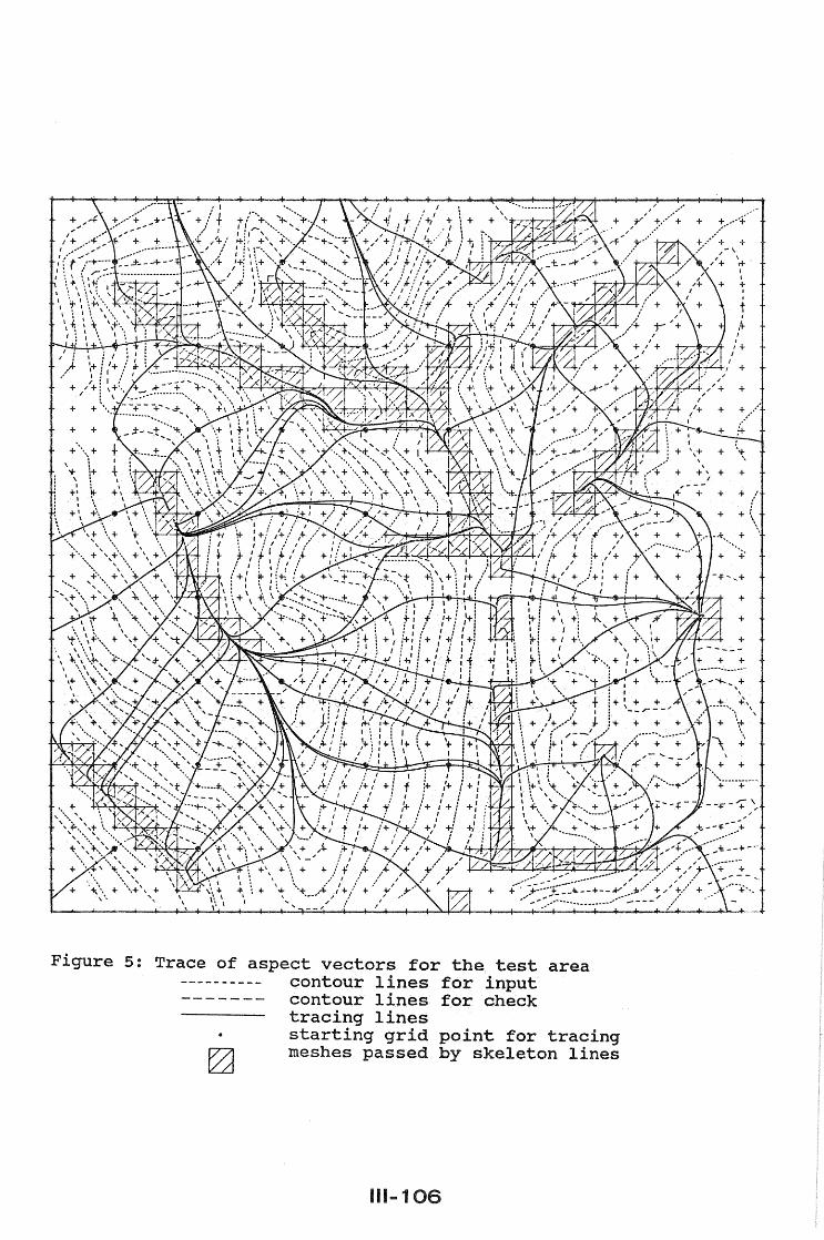
The aspect vector in a mesh can be interpolated bilinearely from the aspect vectors at the four grid points of the mesh. Using this bilinear interpolation, it is possible to trace the aspect starting from grid points. Figure 5 shows the result of tracing, starting from several grid points to higher and lower direction. From figure 5 it is clear, that the characteristics of the terrain surface can be derived reasonably well from the aspect vectors at the grid points. In figure 5, several tracing lines join to one line respectively. These lines are skeleton lines. They can be detected by an analysis of the aspect vectors in the neighbourhood of the tracing lines. If successive aspect vectors on both sides of a tracing line
IU-1

Figure 4: Aspect vectors at the grid points of the test area contour lines for input
------ contour lines for check
111 ... 105
".
Figure 5: Trace of aspect vectors for contour lines contour lines tracing lines
the test for input for check
area
starting grid point for tracing meshes passed by skeleton lines
111 ... 106
I I
+ . , t , It
J
+
+
+
+
+
+

are directed towards this line, it is a skeleton line (see fig.6). In figure 5 meshes passed by skeleton lines are shown by hatching ..
Figure 6: Detection of skeleton lines
s. utilization of Aspect Information in DTH Generation
DTM interpolation by FEM using the second differences of the heights of neighbouring grid points as described in (Ebner and Reiss, 1984), can be altered in such a way, that the aspect information at the grid points is taken into account. In this case the second differences of the heights are applied to points on the trace of the aspect. Tracing from grid point Pi j: in both directions as shown in figure 7 results in the intersections A and B with grid lines. The heights of A and B can be expressed by:
ZA = (1-dy)Zi+1,j + dYZi+1,j+1 ZB = (1-dx)Zi,j-l + dXZi-1,j-l
Pi-1,j+l Pi,j+1
B dx
Pi+l, j+1 A
P'+l · ~ ,)
Pi+l,j-1
(1) (2)
Figure 7: Intersection of aspect tracing line and mesh lines
Let the distance between Pi j and A be lA and between Pi,j and B be lB' then the second dl~ference equation can be expressed as:
V= ZA - z· · J.,J
(3)
The quality of the interpolated DTM is checked by comparing the contour lines derived from the DTM and the original contours.
111 ... 107

.... :;.. __ .
+ + +/"'F' .... t_ " " + +,,+ + + ,,-
,,¥/ + + + + I
+ . ~+ + + + + ..... -----,
\ '" .... i-._~" + + +
Figure 8: Results from the DTM, generated by FEM using the second differences' of the heights of neighbouring grid points
contour lines contour lines contour lines
111 ... 108
for input for check derived from the DTM
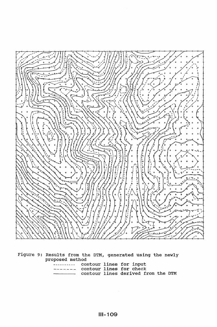
Figure 9: Results from the DTM, proposed method
contour contour contour
generated using the newly
lines lines lines
111-109
for input for check derived from the DTM

Figure 8 shows the results from the DTM, which was generated by FEM using the second differences of the heights of neighbouring grid points. In figure 9 the contours from the newly proposed method using second difference equations from type (3) are represented. A comparison of figure 8 and figure 9 shows, that the utilization of aspect information leads to better contours, especially in the neighbourhood of skeleton lines.
6 .. Conclusion
The first task, the calculation of the aspect at the grid points is solved very satisfactory. The aspect vectors represent the characteristics of the terrain even in critical areas. Moreover, tracing of the aspects allows for a detection of skeleton lines. The second task was the utilization of aspect information in DTM interpolation by FEM. The results show improvements in comparison to the results, obtained up to now, especially in the neighbourhood of skeleton lines. But they do not yet satisfy completely. There are other ways, however, to take into account the quality of the aspect vectors at the grid points. One possibility is to interpolate reference points along the tracing lines of aspect and to use these additional points with lower weights in the present DTM interpolation by FEM. The individual tracing lines may start at the grid points or at the contour lines and are continued in both directions until the nearest contour lines are reached. This approach will be investigated in the near future. In summary, it can be stated, that aspect information from given contours is very valuable for the generation of high quality grid DTMs from contour lines. Interpolation py FEM is a well suited tool for the solution of this task.
References
Ebner, H. and Reiss, P.: Experience with Height Interpolation by Finite Elements.- Photogrammetric Engineering and Remote Sensing 50 (1984),pp.177-182.
Miller, e.L. and Laflamme, R.A.: The Digital Terrain Model Theory and Application. Photogrammetric Engineering 24 (1958),pp. 433- 442.
IU ... 110