II.A Baseband Transmission (Definitions &...
42
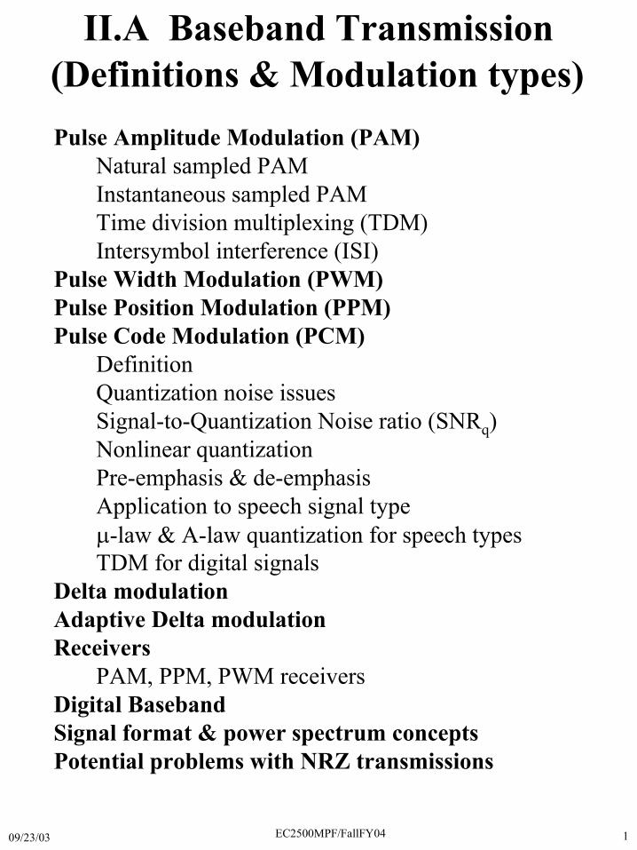
09/23/03 EC2500MPF/FallFY04 1 II.A Baseband Transmission Pulse Amplitude Modulation (PAM) Natural sampled PAM Instantaneous sampled PAM Time division multiplexing (TDM) Intersymbol interference (ISI) Pulse Width Modulation (PWM) Pulse Position Modulation (PPM) Pulse Code Modulation (PCM) Definition Quantization noise issues Signal-to-Quantization Noise ratio (SNR q ) Nonlinear quantization Pre-emphasis & de-emphasis Application to speech signal type -law & A-law quantization for speech types TDM for digital signals Delta modulation Adaptive Delta modulation Receivers PAM, PPM, PWM receivers Digital Baseband Signal format & power spectrum concepts Potential problems with NRZ transmissions (Definitions & Modulation types)
Transcript of II.A Baseband Transmission (Definitions &...
09/23/03 EC2500MPF/FallFY04 1
II.A Baseband Transmission
Pulse Amplitude Modulation (PAM)Natural sampled PAMInstantaneous sampled PAMTime division multiplexing (TDM)Intersymbol interference (ISI)
Pulse Width Modulation (PWM)Pulse Position Modulation (PPM)Pulse Code Modulation (PCM)
DefinitionQuantization noise issuesSignal-to-Quantization Noise ratio (SNRq)Nonlinear quantizationPre-emphasis & de-emphasisApplication to speech signal type�-law & A-law quantization for speech typesTDM for digital signals
Delta modulationAdaptive Delta modulationReceivers
PAM, PPM, PWM receiversDigital BasebandSignal format & power spectrum conceptsPotential problems with NRZ transmissions
(Definitions & Modulation types)
09/23/03 EC2500MPF/FallFY04 2
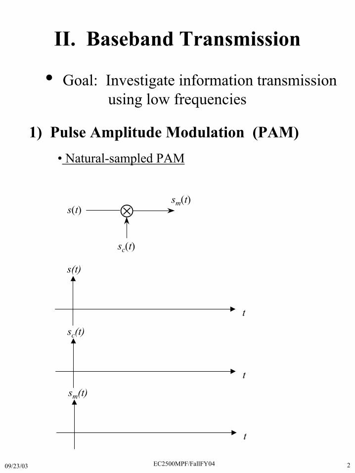
II. Baseband Transmission
• Goal: Investigate information transmission using low frequencies
1) Pulse Amplitude Modulation (PAM)• Natural-sampled PAM
�s(t)sm(t)
sc(t)
s(t)
t
sc(t)
t
sm(t)
t
09/23/03 EC2500MPF/FallFY04 3
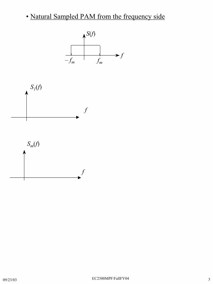
S(f)
f– fm fm
S1(f)
f
Sm(f)
f
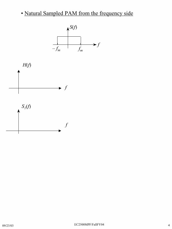
• Natural Sampled PAM from the frequency side
09/23/03 EC2500MPF/FallFY04 4
S(f)
f– fm fm
H(f)
S1(f)
f
f
• Natural Sampled PAM from the frequency side

09/23/03 EC2500MPF/FallFY04 5
�s(t)sm(t)
sc(t)
H(f)s1(t)
• Instantaneous-sampled PAM
s(t)
t
sc(t)
t
s1(t)
t
t
sm(t)
09/23/03 EC2500MPF/FallFY04 6
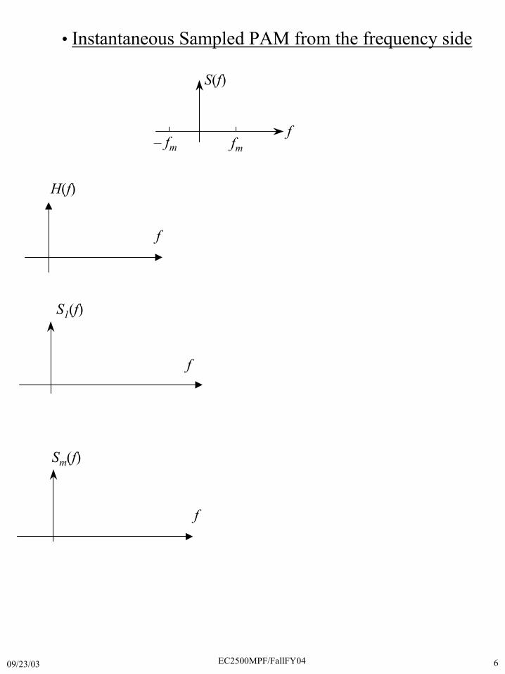
H(f)
S1(f)
f
f
Sm(f)
f
• Instantaneous Sampled PAM from the frequency side
S(f)
f– fm fm
09/23/03 EC2500MPF/FallFY04 7
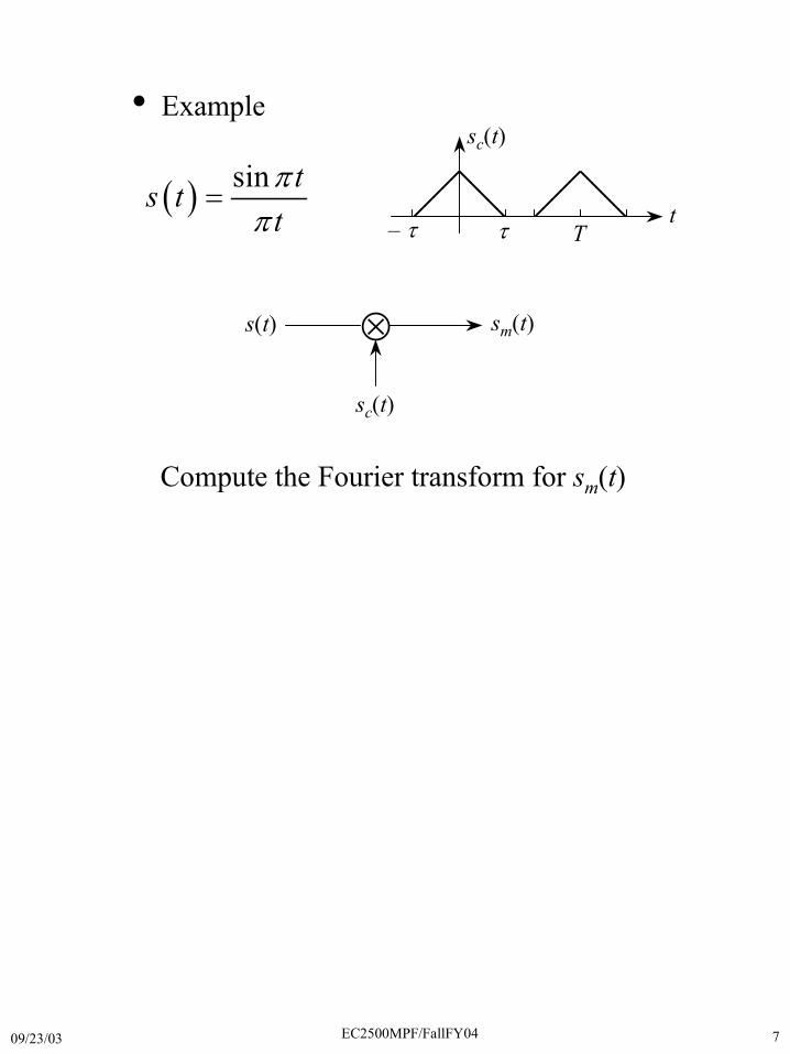
�s(t) sm(t)
sc(t)
� �sin ts t
t�
�
�
sc(t)
t– � � T
Compute the Fourier transform for sm(t)
• Example

09/23/03 EC2500MPF/FallFY04 8
09/23/03 EC2500MPF/FallFY04 9
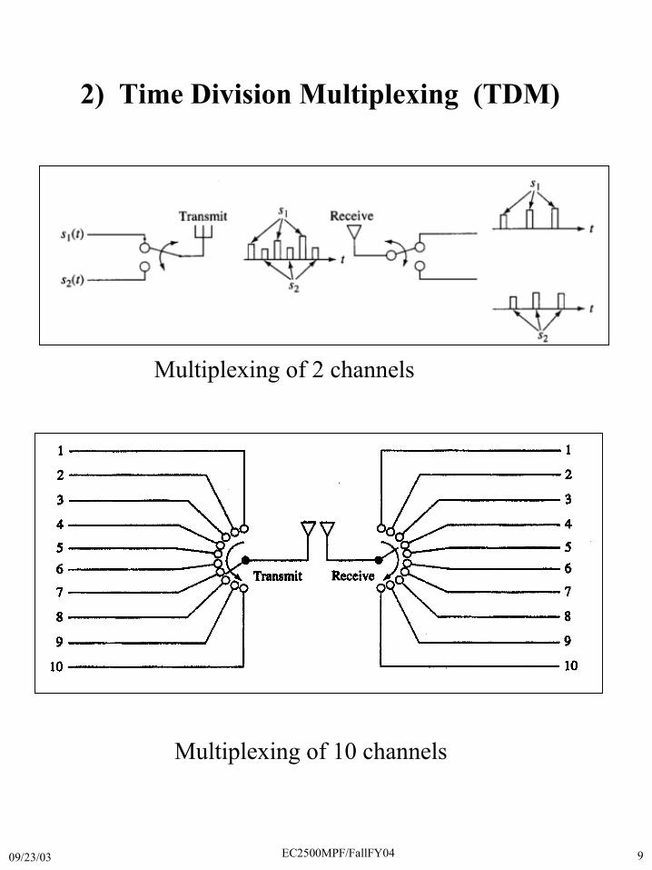
2) Time Division Multiplexing (TDM)
Multiplexing of 2 channels
Multiplexing of 10 channels
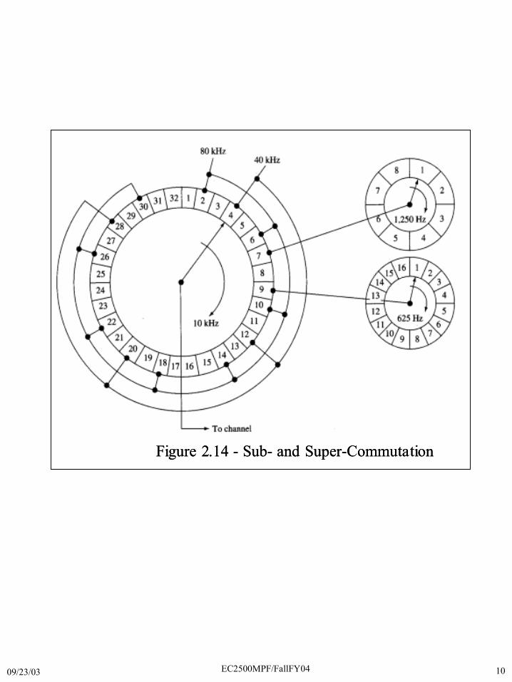
09/23/03 EC2500MPF/FallFY04 10
Figure 2.14 - Sub- and Super-CommutationFigure 2.14 - Sub- and Super-Commutation
09/23/03 EC2500MPF/FallFY04 11
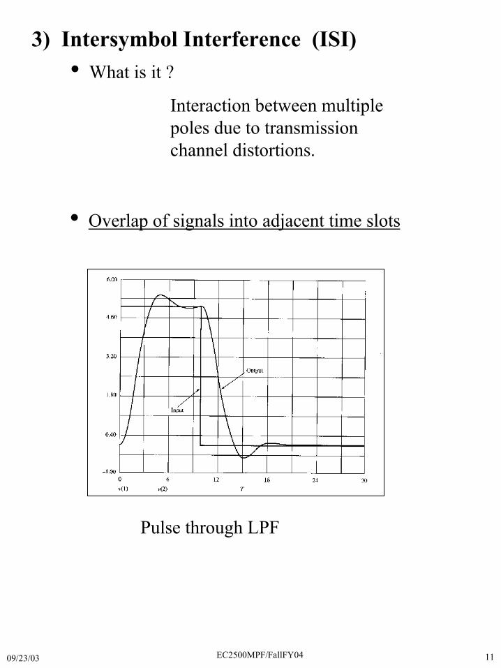
• What is it ?
Interaction between multiplepoles due to transmissionchannel distortions.
3) Intersymbol Interference (ISI)
• Overlap of signals into adjacent time slots
Pulse through LPF
09/23/03 EC2500MPF/FallFY04 12
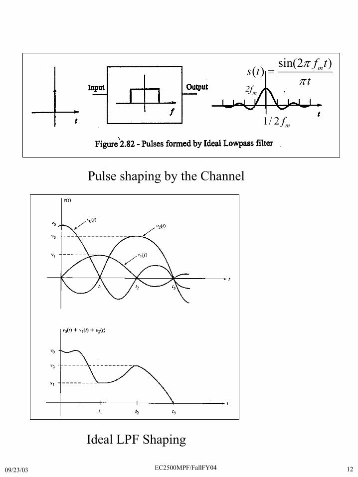
Pulse shaping by the Channel
sin(2 )( ) mf t
s tt�
�
�
1/ 2 mf
2fm
Ideal LPF Shaping
09/23/03 EC2500MPF/FallFY04 13
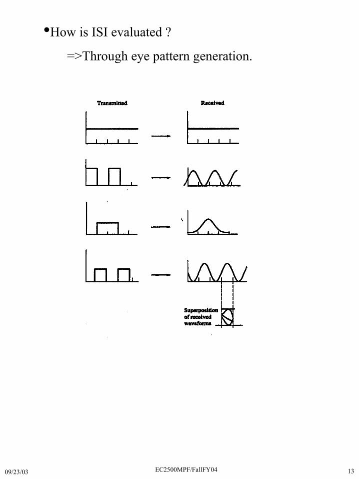
•How is ISI evaluated ?
=>Through eye pattern generation.
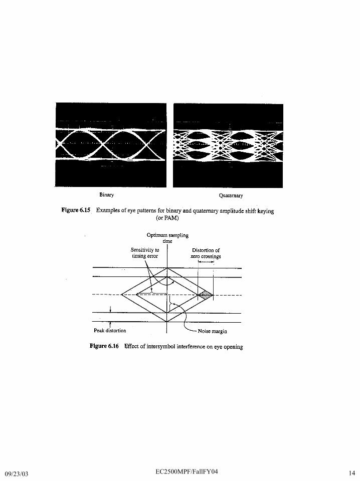
09/23/03 EC2500MPF/FallFY04 14
09/23/03 EC2500MPF/FallFY04 15
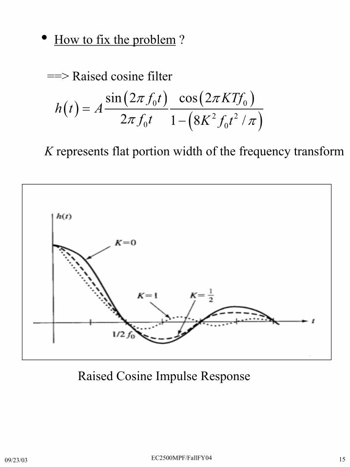
==> Raised cosine filter
� �� � � �
� �0 0
2 20 0
sin 2 cos 22 1 8 /
f t KTfh t A
f t K f t� �
� �
�
�
K represents flat portion width of the frequency transform
Raised Cosine Impulse Response
• How to fix the problem ?
09/23/03 EC2500MPF/FallFY04 16
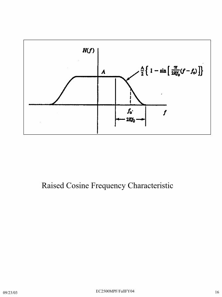
Raised Cosine Frequency Characteristic
09/23/03 EC2500MPF/FallFY04 17
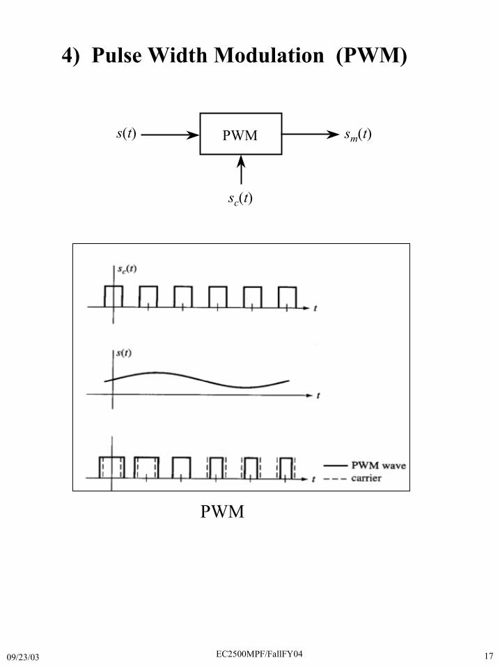
s(t) sm(t)
sc(t)
PWM
4) Pulse Width Modulation (PWM)
PWM

09/23/03 EC2500MPF/FallFY04 18
• PWM Generator
09/23/03 EC2500MPF/FallFY04 19
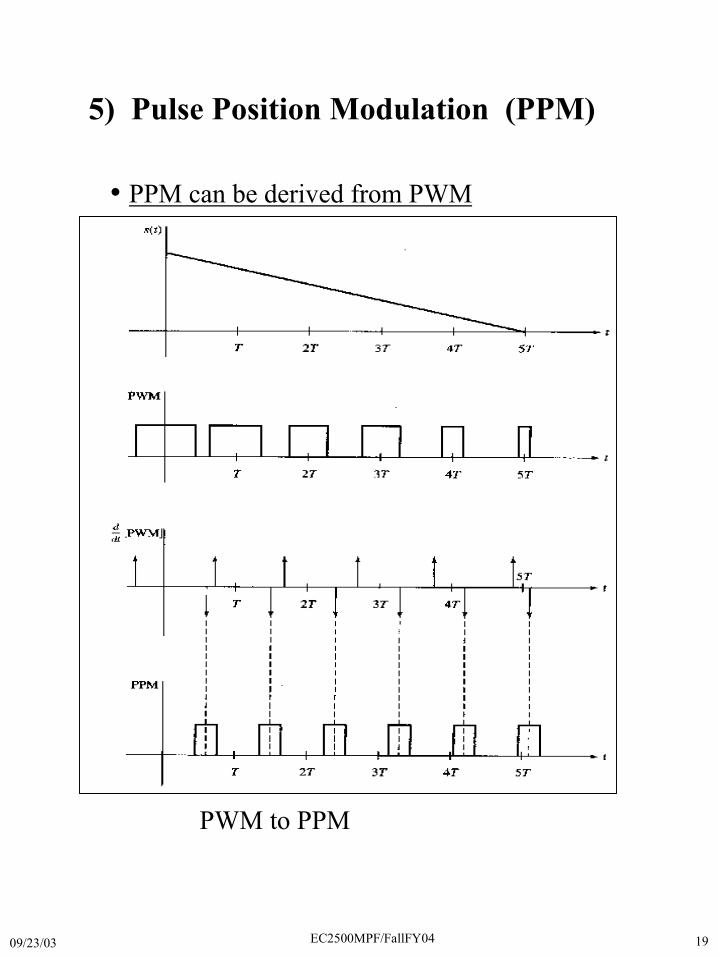
5) Pulse Position Modulation (PPM)
• PPM can be derived from PWM
PWM to PPM
09/23/03 EC2500MPF/FallFY04 20
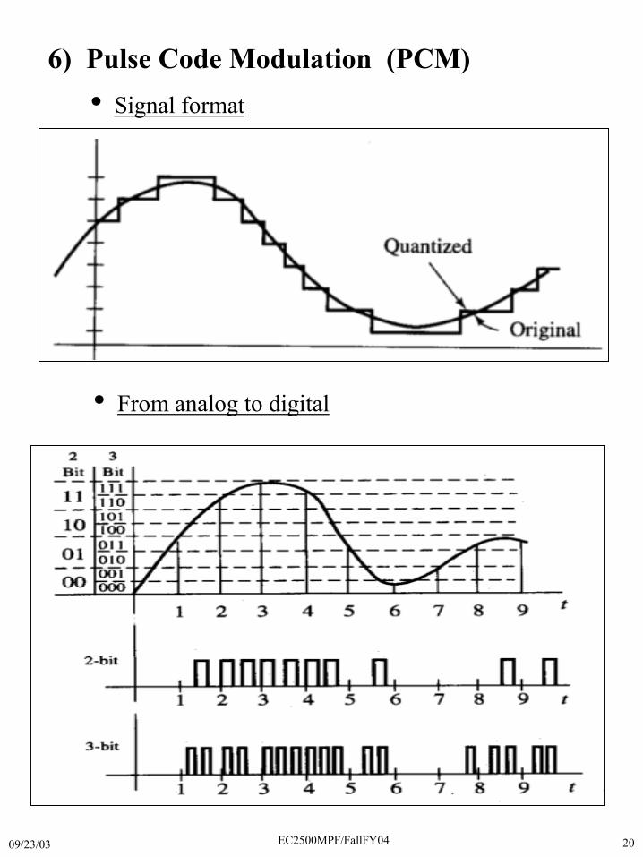
• Signal format
6) Pulse Code Modulation (PCM)
• From analog to digital
09/23/03 EC2500MPF/FallFY04 21
• Quantization noise issues
- Quantization error is a measure of effectivenessof a quantization scheme
- Quantization noise level is directly related to thenumber of quantization levels
- Assume quantization error e(n) to be equally likelyto occur in the range D
pdf of e
p(e)
e
s(t)
t
09/23/03 EC2500MPF/FallFY04 22
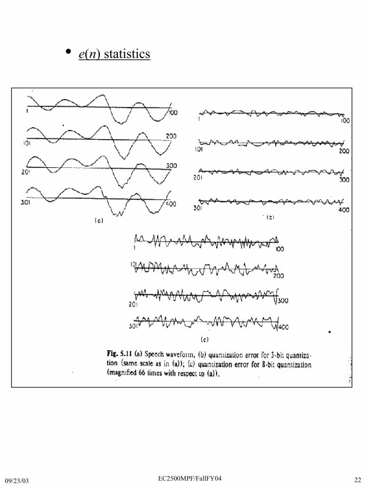
• e(n) statistics
09/23/03 EC2500MPF/FallFY04 23
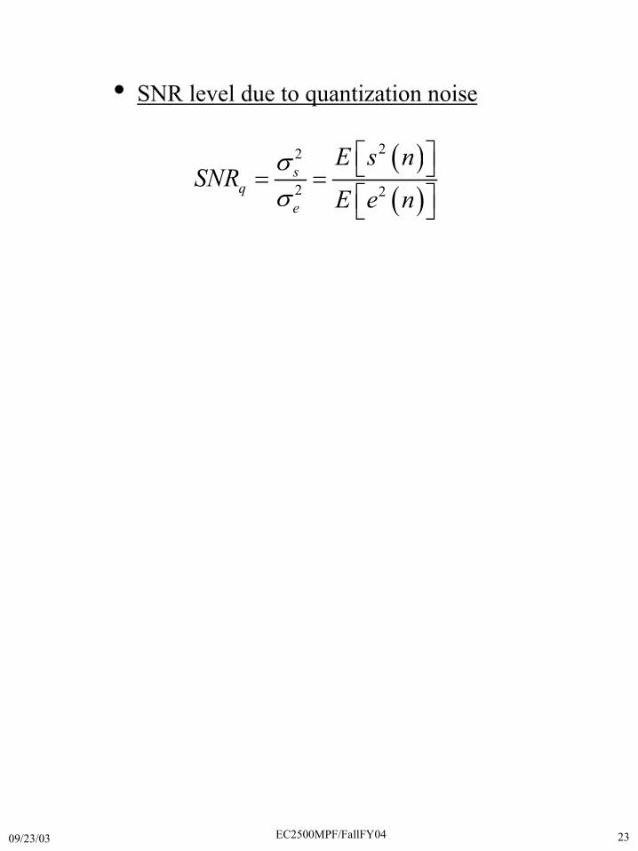
• SNR level due to quantization noise
� �
� �
22
2 2s
qe
E s nSNR
E e n�
�
� �� �� �� �� �
09/23/03 EC2500MPF/FallFY04 24
• Example
� � � �2cos 500s t t��
1) Compute SNRq when using 8-bit PCM
2) Compute the minimum number of bits needed to get SNRq � 20 dB
09/23/03 EC2500MPF/FallFY04 25
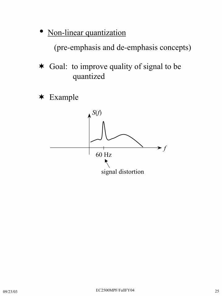
• Non-linear quantization
(pre-emphasis and de-emphasis concepts)
� Goal: to improve quality of signal to be quantized
� Example
S(f)
f60 Hz
signal distortion
09/23/03 EC2500MPF/FallFY04 26
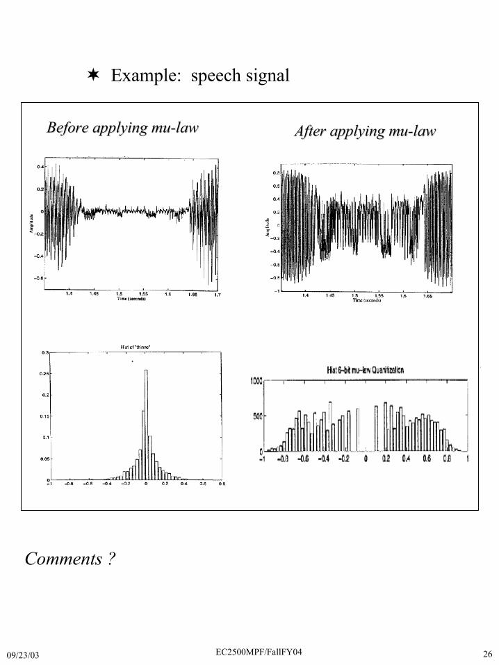
� Example: speech signal
Before applying Before applying mumu-law-law After applying After applying mumu-law-law
Comments ?
09/23/03 EC2500MPF/FallFY04 27
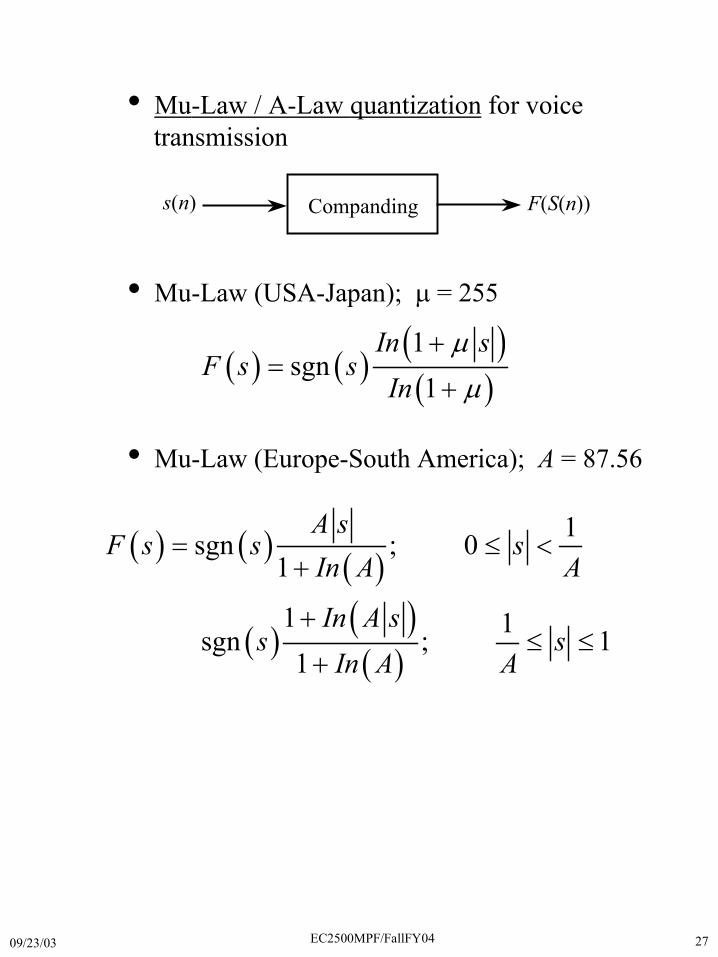
• Mu-Law / A-Law quantization for voice transmission
• Mu-Law (USA-Japan); � = 255
• Mu-Law (Europe-South America); A = 87.56
� � � �� �� �
1sgn
1In s
F s sIn
�
�
�
�
�
� � � �� �
� �� �� �
1sgn ; 01
1 1sgn ; 11
A sF s s s
In A A
In A ss s
In A A
� � �
�
�
� �
�
s(n) F(S(n))Companding
09/23/03 EC2500MPF/FallFY04 28
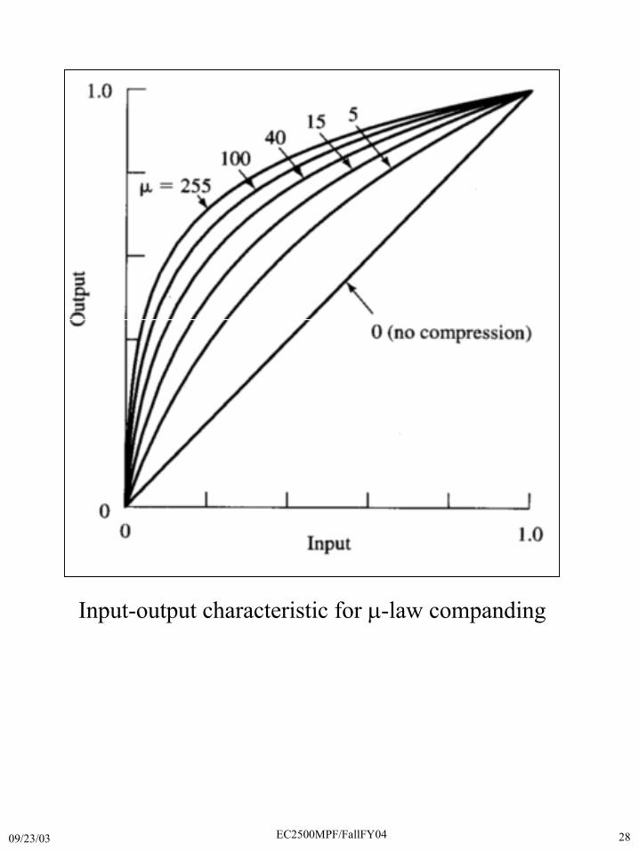
Input-output characteristic for �-law companding
09/23/03 EC2500MPF/FallFY04 29
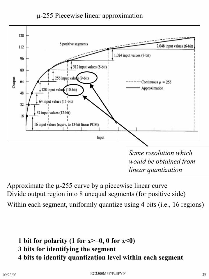
�-255 Piecewise linear approximation
Same resolution whichwould be obtained fromlinear quantization
1 bit for polarity (1 for x>=0, 0 for x<0)3 bits for identifying the segment4 bits to identify quantization level within each segment
Approximate the �-255 curve by a piecewise linear curveDivide output region into 8 unequal segments (for positive side)Within each segment, uniformly quantize using 4 bits (i.e., 16 regions)
09/23/03 EC2500MPF/FallFY04 30
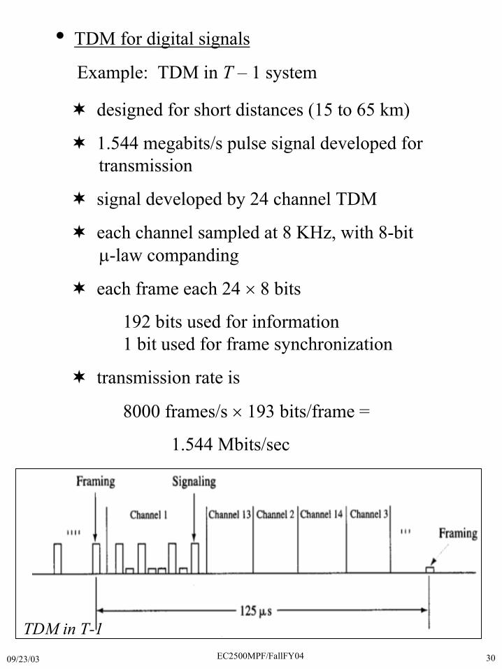
• TDM for digital signals
Example: TDM in T – 1 system
� designed for short distances (15 to 65 km)
� 1.544 megabits/s pulse signal developed for transmission
� signal developed by 24 channel TDM
� each channel sampled at 8 KHz, with 8-bit �-law companding
� each frame each 24 � 8 bits
192 bits used for information 1 bit used for frame synchronization
� transmission rate is
8000 frames/s � 193 bits/frame =
1.544 Mbits/sec
TDM in T-1

09/23/03 EC2500MPF/FallFY04 31
7) Delta Modulation
• Simplified 1-bit PCM
• Quantization issues
slope overload granular noise
09/23/03 EC2500MPF/FallFY04 32
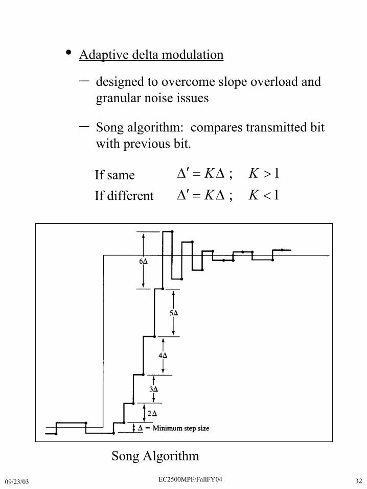
• Adaptive delta modulation
– designed to overcome slope overload and granular noise issues
– Song algorithm: compares transmitted bit with previous bit.
If sameIf different
; 1; 1
K KK K
�� � � �
�� � � �
Song Algorithm
09/23/03 EC2500MPF/FallFY04 33
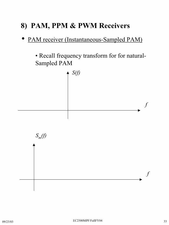
8) PAM, PPM & PWM Receivers
• PAM receiver (Instantaneous-Sampled PAM)
• Recall frequency transform for for natural-Sampled PAM
f
S(f)
f
Sm(f)
09/23/03 EC2500MPF/FallFY04 34
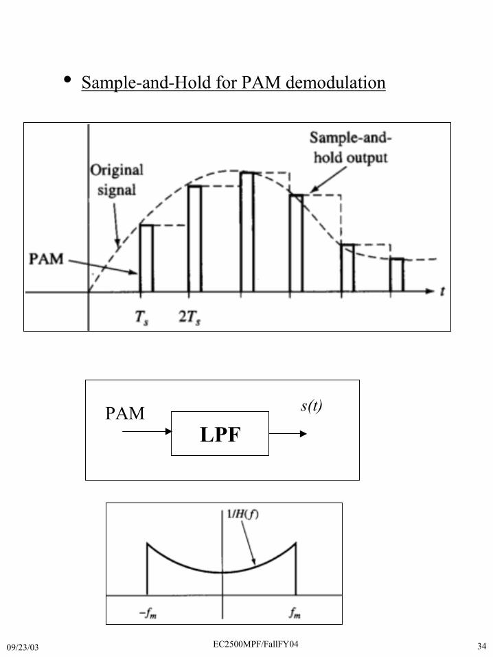
• Sample-and-Hold for PAM demodulation
LPFPAM s(t)
09/23/03 EC2500MPF/FallFY04 35
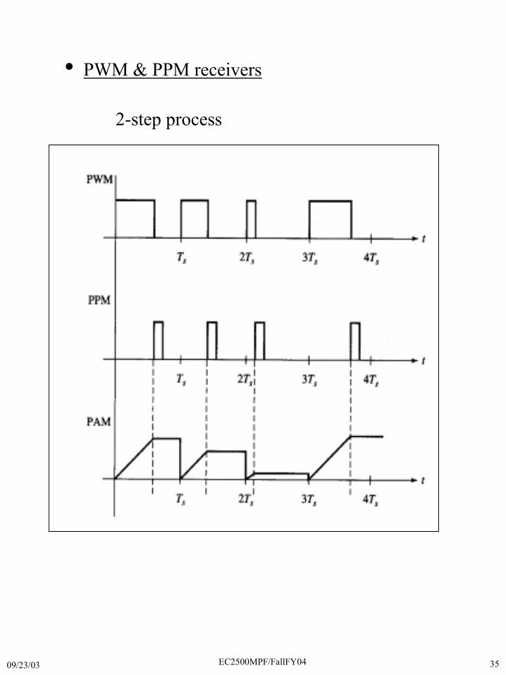
• PWM & PPM receivers
2-step process
09/23/03 EC2500MPF/FallFY04 36
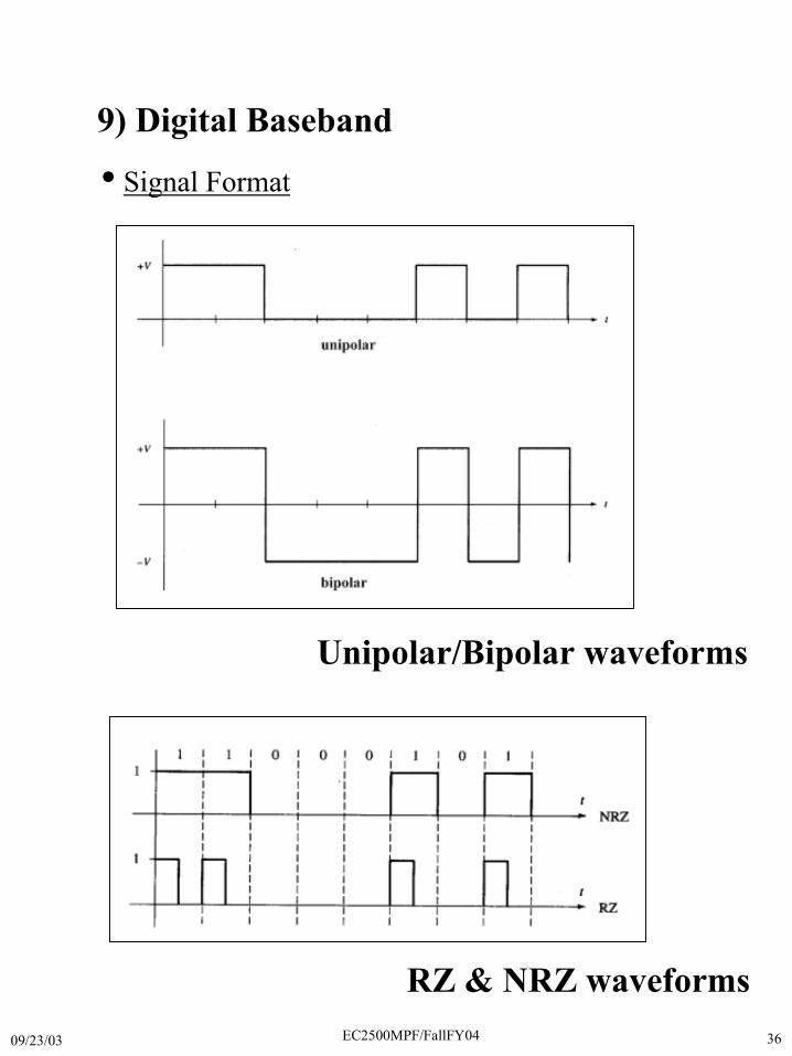
9) Digital Baseband
Unipolar/Bipolar waveforms
• Signal Format
RZ & NRZ waveforms
09/23/03 EC2500MPF/FallFY04 37
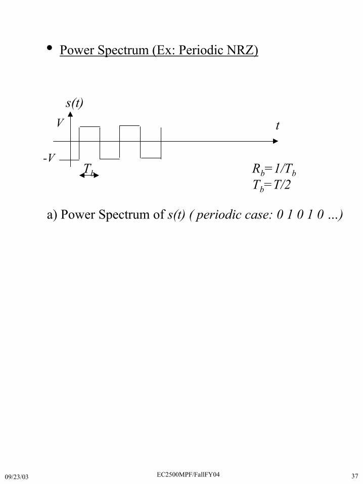
• Power Spectrum (Ex: Periodic NRZ)
t
s(t)
Tb Rb=1/TbTb=T/2
a) Power Spectrum of s(t) ( periodic case: 0 1 0 1 0 …)
V
-V

09/23/03 EC2500MPF/FallFY04 38
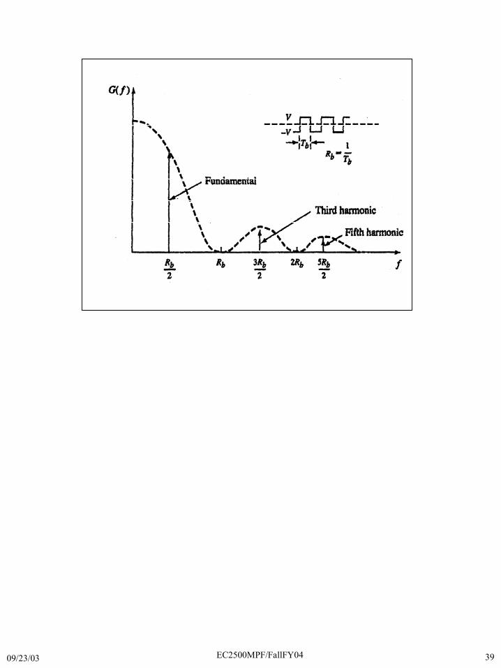
09/23/03 EC2500MPF/FallFY04 39
Figure 2.27
09/23/03 EC2500MPF/FallFY04 40
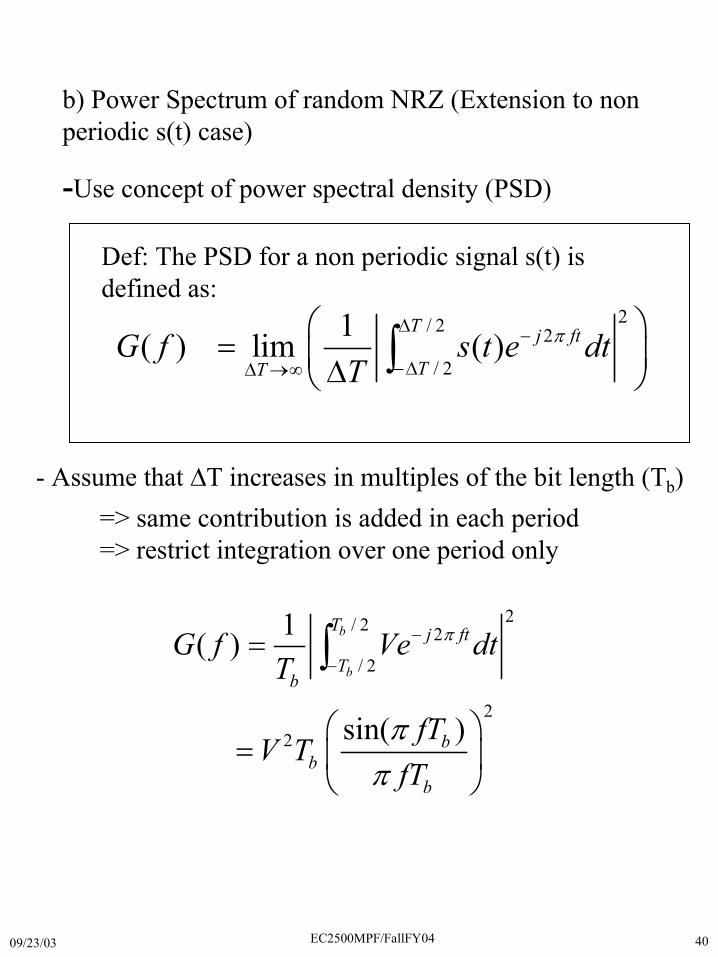
b) Power Spectrum of random NRZ (Extension to nonperiodic s(t) case)
-Use concept of power spectral density (PSD)
- Assume that �T increases in multiples of the bit length (Tb)=> same contribution is added in each period=> restrict integration over one period only
2/ 2 2
/ 2
22
1( )
sin( )
b
b
T j ft
Tb
bb
b
G f Ve dtT
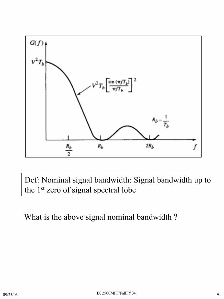
fTV T
fT
�
�
�
�
�
�
� �� � �
� �
�
2/ 2 2
/ 2
1( ) lim ( )T j ft
TTG f s t e dt
T�
��
��� ��
� �� � ��� �
�
Def: The PSD for a non periodic signal s(t) isdefined as:
09/23/03 EC2500MPF/FallFY04 41
Def: Nominal signal bandwidth: Signal bandwidth up tothe 1st zero of signal spectral lobe
What is the above signal nominal bandwidth ?
09/23/03 EC2500MPF/FallFY04 42
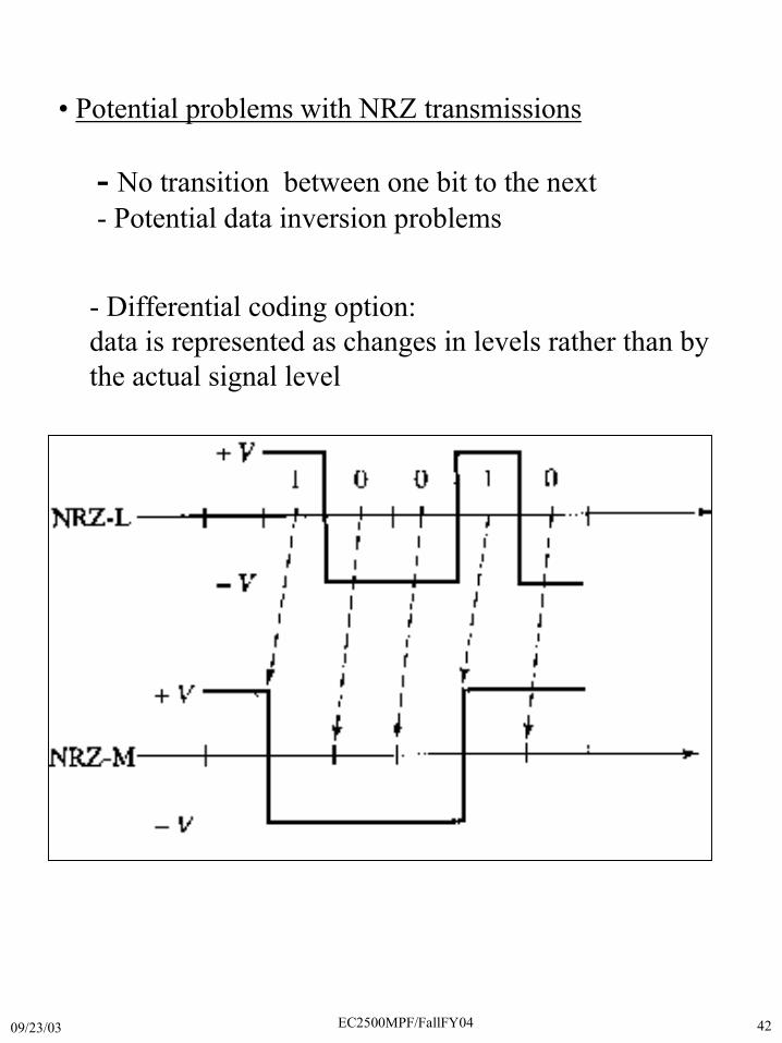
• Potential problems with NRZ transmissions
- No transition between one bit to the next- Potential data inversion problems
- Differential coding option:data is represented as changes in levels rather than bythe actual signal level