· ii) Type : Micadur-Compact iii) Corona protection : outer d) Dielectric test voltage kV : 28.6...
30
Transcript of · ii) Type : Micadur-Compact iii) Corona protection : outer d) Dielectric test voltage kV : 28.6...


BHARAT ALUMINIUM COMPANY LTD.
SPECIFICATIONS FOR
SYNCHRONOUS GENERATOR 1.00.00 GENERAL
1.01.00 Make :
Jinan Power Equipment Factory
1.02.00 Type :
WX21Z-073LLT
1.03.00 Reference Standard :
GB/T7064-2002
1.04.00 Enclosure :
IP54
1.05.00 Type of Cooling
a) Stator Winding :
Air-cooled
b) Stator Core :
Air-cooled
c) Rotor :
Air-cooled
d) Main Exciter :
ÎÞ£¬¾²Ö¹Àø´Å
1.06.00 Rated Speed r.p.m. :
3000
2.00.00 MAIN RATINGS
2.01.00 Guaranteed Ratings at designed closed cycle auxiliary cooling water inlet temperature and 0.8 Lagging Power Factor
a) Rated output MW :
135
b) Maximum continuous rating (M.C.R.) MW :
135
c) Rated Power Factor :
0.8
d) Rated Terminal Voltage KV :
13.8
e) Rated Stator Current Amps. :
7060
f) Phase Nos. :
3

g) Rated Frequency Hz :
50
h) Excitation at rated output
i) Voltage Volts :
252.8
ii) Current Amps. :
1526.7
i) Short Circuit Ratio at rated output :
0.475
j) Permissible ± Tolerance in S.C.R. :
±15%
2.02.00 Ratings at designed closed cycle auxiliary cooling water inlet temperature and 0.85 lagging Power Factor
a) Continuous output MW :
143
b) Maximum continuous rating (MCR) MW :
143
c) Excitation at Continuous Output
i) Voltage Volts :
245.0
ii) Current Amps :
1478.8
2.03.00 Ratings at designed closed cycle auxiliary cooling water inlet temperature and 0.9 Lagging Power Factor
a) Continuous output MW :
151
b) Maximum continuous rating (MCR) MW :
151
c) Excitation at Continuous Output
i) Voltage Volts :
235.8
ii) Current Amps :
1422.8
3.00.00 PERFORMANCE
3.01.00 Efficiency at rated p.f.
a) 100% load
% : 98.72
b) 75% load
% : 98.57

c) 50% load
% : 98.15
d) 40% load
% : 97.5
e) 25% load
% : 96.73
3.02.00 At Generator Rated Output, Rated Speed & Power Factor, the Permissible Variation Range in
a) Terminal Voltage
% : ±5
b) Frequency
% : -5 % to +3 %
c) Absolute sum of combined voltage and frequency variation
%
: ±5
3.05.00 Generator Reactive Capability
a) Maximum Inductive Loading (Zero Lag) MVAR : 110
b) Maximum Capacitive Loading (Zero Lead)
MVAR : 110
c) Capacitive Loading at Rated Load (MW) and Voltage
MVAR : 101.25
3.06.00 Permissible Unbalanced Loading subject to current not being exceeded the rated current in any phase
a) Maximum continuous negative sequence current - I2
% : 8
b) Maximum value of I22t for transient
operation under system fault (I2 in p.u. and t in secs)
: 10
3.07.00 Generator Asynchronous Operation
a) Permissible Load
% f.l. : 67.5
b) Duration
min. : 15
3.09.00 Overload Performance
a) Stator Current
% f.l. : 150

b) Time
Sec. : 30
3.11.00 Maximum Continuous Generator Capability under One cooler section out of operation
MVA : 80%
4.00.00 TEMPERATURES
4.01.00 Ambient Temperature
a) Cooling Water at Inlet to Heat Exchanger
°C : 33
b) Ambient Air
°C :
4.02.00 Guaranteed Temperature Rise over specified Ambient Temperature
a) Stator Winding
°C : 60 Deg C
b) Stator Core -
i) In contact with Insulated Winding
°C : 55 Deg C
ii) Not in contact with Insulated Winding
°C : 55 Deg C
c) Rotor Winding
°C : 50 Deg C
5.07.00 Maximum Allowable Overspeed
r.p.m. : 3600
6.00.00 REACTANCES ETC. (In % at Rated MVA & KV)
6.01.00 Direct Axis Reactances (Saturated/ Unsaturated)
a) Synchronous - xd
% : 235/210.6
b) Transient - xd'
% : 25.5/23.9
c) Sub-transient - xd"
% : 19.3/15.1

6.02.00 Quadrature Axis Reactances (Saturated/ Unsaturated)
a) Synchronous - xq
% : 220.2/220.2
b) Transient - xq'
% : 41.5/37.3
c) Sub-transient - xq"
% : 20.7/15.9
6.03.00 Negative Sequence Reactance - x2
% : 19.7/15.7
6.04.00 Zero Sequence Reactance - x0
% : 8.3/6.5
6.05.00 Potier Reactance - Xp
% : 25.3
6.06.00 Permissible Tolerance in all Guaranteed Reactance Values
% : ±15
6.07.00 Effective Winding Capacitance to Earth
a) Per Phase
mfd : 0.437
b) All phases connected to earth
mfd : 1.311
6.08.00 Effective Surge Impedance to Neutral per phase
ohm :
6.09.00 Armature Resistance per Phase at
a) 25°C
ohm : 0.001028
b) 75°C
ohm : 0.001226
6.10.00 Field Resistance at
a) 25°C
ohm : 0.1256
b) 75°C
ohm : 0.1491
7.00.00 TIME CONSTANTS
7.01.00 Direct Axis Transient
a) Open Circuit Time Constant Td'o
Sec. : 9.455
b) Short Circuit Time Constant Td'
Sec. : 1.028
7.02.00 Direct Axis Sub-transient

a) Open Circuit Time Constant Td"o
Sec : 0.023
b) Short Circuit Time Constant Td"
Sec : 0.017
7.03.00 Quadrature Axis Transient
a) Open Circuit Time Constant Tq'o
Sec : 0.905
b) Short Circuit Time Constant Tq'
Sec : 0.170
7.04.00 Quadrature Axis Sub-transient
a) Open Circuit Time Constant Tq"o
Sec : 0.034
b) Short Circuit Time Constant Tq"
Sec : 0.017
7.05.00 Armature Short Circuit Time Constant Ta
Sec : 0.578
8.00.00 SHORT CIRCUIT CURRENT (In p.u.)
8.01.00 Sub-transient Current
a) 3-Phase Short Circuit
% : 663.6
b) 2-Phase Short Circuit
% : 497.6
c) 1-Phase to Neutral Short Circuit
% : 695.1
8.02.00 Transient Current
a) 3-Phase Short Circuit
% : 418.8
b) 2-Phase Short Circuit
% : 397.1
c) 1-Phase to Neutral Short Circuit
% : 577.3
8.03.00 Steady State Current
a) 3-Phase Short Circuit
% : 146
b) 2-Phase Short Circuit
% : 236
c) 1-Phase to Neutral Short Circuit
% : 397
9.00.00 DESIGN AND CONSTRUCTION
9.01.00 Stator Core

a) Type of Mounting : laminated
b) Grade of Steel
i) Thickness mm : 0.5
ii) Loss figure Watt / Kg : 0.0031
c) Generator air gap mm : 55
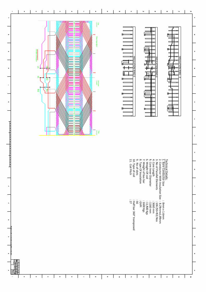
9.02.00 Stator Winding
a) Winding transposed Yes/No : Yes
b) Phase connection : Y
c) Insulation
i) Class : F
ii) Type : Micadur-Compact
iii) Corona protection : outer
d) Dielectric test voltage kV : 28.6
e) Impulse voltage strength kVp :
f) Insulation Class
i) Slot : F
ii) End coil : F
g) Arrangement of partial discharge measurement within stator windings during running condition of generator
Yes/No : yes
9.03.00 Terminals
a) No. of Terminals brought out
i) Phase : 3
ii) Neutral : 3
b) Type of terminal bushings : No
c) Net space available for mounting bushing current transformers
: no

d) Bushing CT furnished Yes/No : No
e) If yes state No. and specification of Bushing CT
: No
f) Dielectric test voltage KV :
9.04.00 Rotor
a) Material for
i) Rotor forging : 26NiCrMoV145
ii) Retaining ring : X8CrMn1818
iii) Rotor wedge : CuNi2Si
9.05.00 Rotor Winding
a) Insulation
i) Class : F
ii) Type : Nomex
b) Turns per pole : 12
c) Dielectric test voltage KV : 2.528
9.06.00 Bearing
a) Type : Bracket
b) Oil quantity per bearing lit/sec : 164
c) Oil pressure Kg/ cm²(g) : 1.2
10.00.00 EXCITATION SYSTEM
10.01.00 Nominal Exciter response ratio
a) With generator at no load Sec-1 :
b) With generator at rated load Sec-1 : ¡Ý2
10.02.00 Excitation System voltage response time Sec. : ¡Ü0.1
10.03.00 Ceiling Current Amps : 3053.4
10.04.00 Ceiling Voltage Volts : 505.6

10.05.00 Ceiling Duty duration Sec. :
10.06.00 "Rapid De-fluxing" time and the technique used
Sec. : 1.8
10.07.00 Type pf de-excitation system : ¿ª¹ØÃð´Å
10.08.00 Field reversal capability :
10.09.00 Excitation system time constant Sec. :
10.10.00 Auxiliary power requirement KW :
10.11.00 Forced Cooling System requirement :
10.12.00 Base field voltage Volts :
10.13.00 Natural frequency of T.G. torsional oscillations
Hz :
10.14.00 Space requirement including clearance mm :
10.15.00 Shelf life of the solid state spares :
10.16.00 Time for which spare parts (including solid state) will be kept available
:
11.00.00 AUTOMATIC VOLTAGE REGULATOR
11.01.00 Make : Guangzhou Electric Apparatus Research Institute
11.02.00 Type : Exc2000
11.03.00 Power supply to regulator Volts : 252.8
11.04.00 Range of Voltage adjustments
a) Auto : 10-130
b) Manual : 5-130
11.05.00 Range of Operation
a) Frequency Hz :
b) Temperature °C : 0-50
11.06.00 Accuracy : £¼0.5%
11.07.00 Dead Band :

11.08.00 Response time to apply field forcing voltage with a 5% drop
milli sec.
:
19.00.00 GENERATOR LOSSES
19.01.00 Iron Loss
a) At no load KW :
b) At full load KW : 292.8
19.02.00 Stator Copper loss KW : 183.4
19.03.00 Rotor Copper Loss
a) At no load KW :
b) At full load KW : 298.6
18.04.00 Stray Load Loss KW : 203.0
18.05.00 Friction and windage loss KW : 752.5
18.06.00 Excitation Losses
a) Exciter loss KW : ÎÞ
b) Rotary rectifier loss KW : ÎÞ
c) Collector-brush contact loss KW : 17.1
20.00.00 MAIN WEIGHTS
20.01.00 Weight of the Generator Stator Tonnes : 131.6
20.02.00 Weight of the Generator Rotor Tonnes : 33.7
20.03.00 Weight of the Complete Generator (Stator plus Rotor)
Tonnes : 172.1

Serial number
Name Unit Design Value
1 Make Jinan Electric Equiooments Ltd, China Generator Type WX21Z-073LLT Rated Capacitance MVA 168. 75 Rated Power MW 135 Maximum Continuous
Output Power MW 145
Rated Power Factor 0. 8 Rated Stator Voltage KV 13. 8 Rated Stator Current A 7060 Rated Frequency HZ 50 Rated Rotate Speed r/min 3000 Rated Excitation Voltage V 252. 8 Rated Excitation Current A 1526. 7 Connection Mode of
Stator Coil Y
Cooling Mode Air Cooling Excitation Mode Stator Thyristor 2 Parameter Performance Allowable Frequency
Error ±% -5— +3
Serial number
Name Unit Design Value
Allowable Stator Voltage Error
±% 5
Leading Phase Operation Ability
MW 135,Leading Phase 0. 95
Leading Phase Operation Time
Long Time
3 Loss and Efficiency Stator Circuit Copper
Loss KW 183. 4
Stator Iron Loss KW 292. 8 Excitation Loss KW 298. 6+17. 1 Short Circuit Additional
Loss KW 203
Mechanism Loss KW 752. 5 Total Loss KW 1747. 4 Fully Loaded
Efficiency % 98. 72
4 Insulation Class and Temperature
Stator Circuit Insulation Class
F
Rotator Circuit Insulation Class
F
Stator Iron Core Insulation Class
F
Stator Circuit Limit Temperature
℃ 120
Rotator Circuit Limit ℃ 105

Temperature Stator Iron Core Limit
Temperature ℃ 120
Generator Inlet Air Temperature
℃ ≤40
Generator Outlet Air Temperature
℃ ≤90
5 Flow Rate and Temperature of Cooling Medium
Air Condenser Number 6 Air Condenser Inlet
Water Temperature ℃ ≤33
Air Condenser Outlet Water Temperature
℃ ≤38
Bearing Lubricating Oil Inlet Temperature
℃ ≤45
Bearing Lubricating Oil Outlet Temperature
℃ ≤65
Bearing Lubricating Oil Allowance
L/min 164
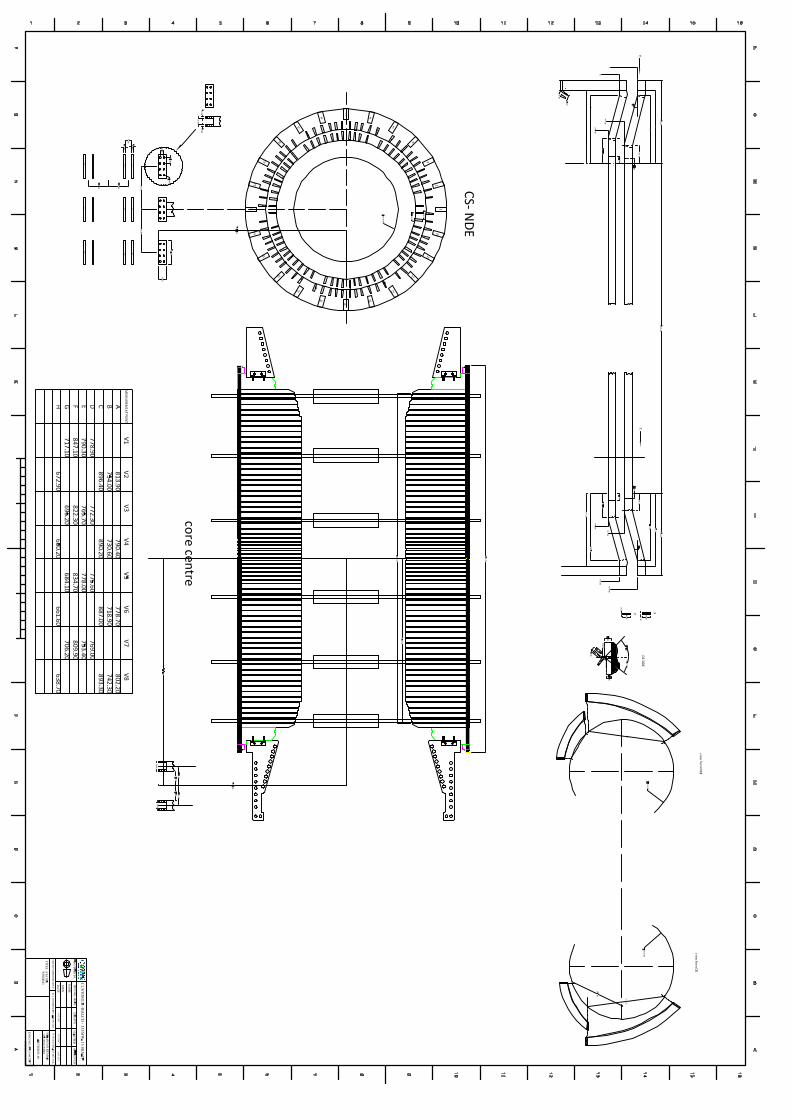
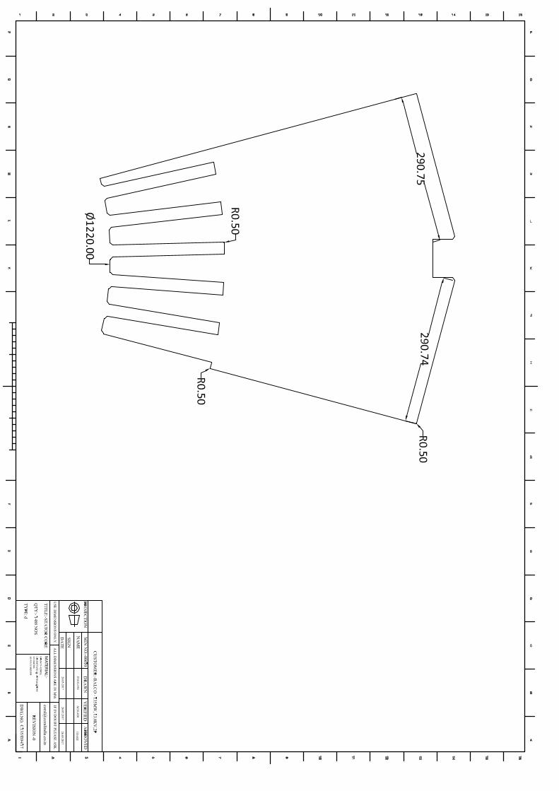
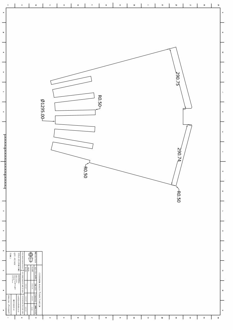
6 The Main Dimension Stator Iron Core Inside
Diameter mm 1160
Stator Iron Core Outside Diameter
mm 250
Stator Iron Core Length mm 3360 Grip (Single Side) mm 55 The number of Stator
Slot 66
The Number of Stator Circuit Parallel Branch
2
The Number of Circuit in Slot
212
Total Weight of Stator t 131. 6 Rotor Outside Diameter mm 1050 Rotor Effective Length mm 3660 The number of Rotor
Slot 32
Turn Number in Rotor per Slot
12
Rotor Inter-turn Insulation Thickness
mm 0. 76


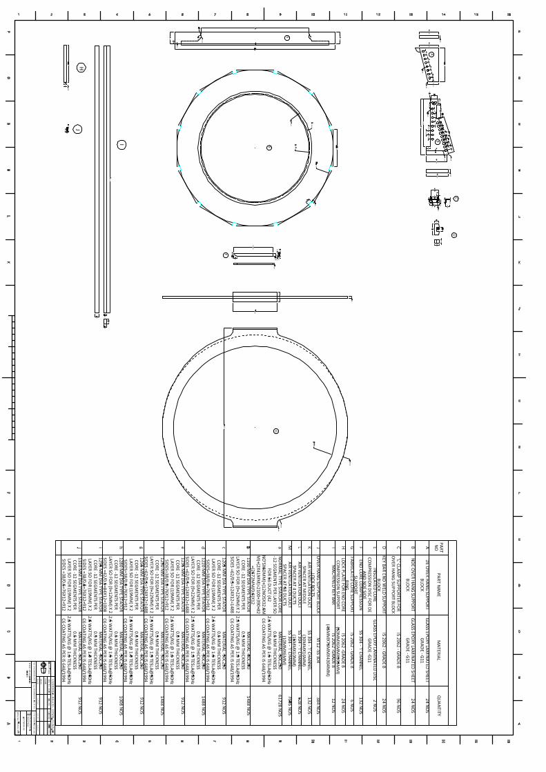
Scope of Vendor Scope of the Vendor will be as mentioned below:
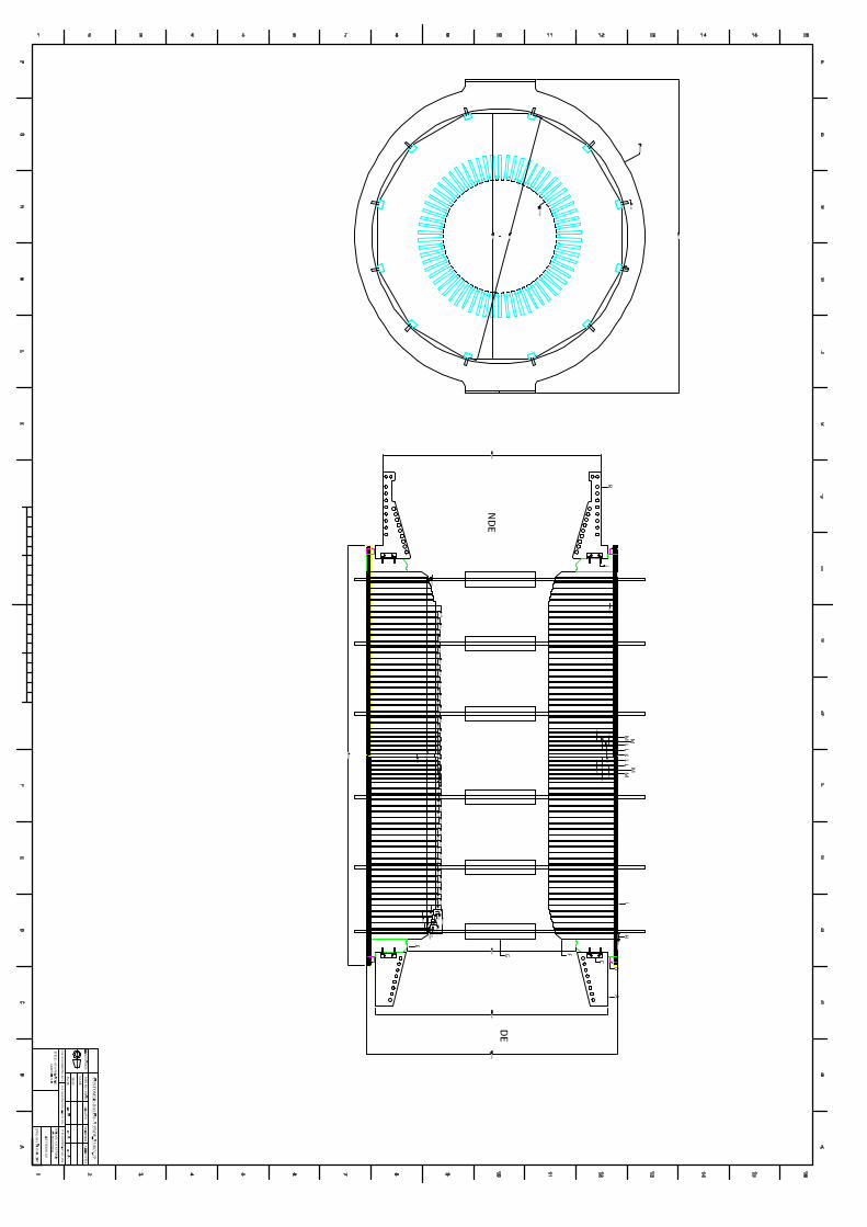
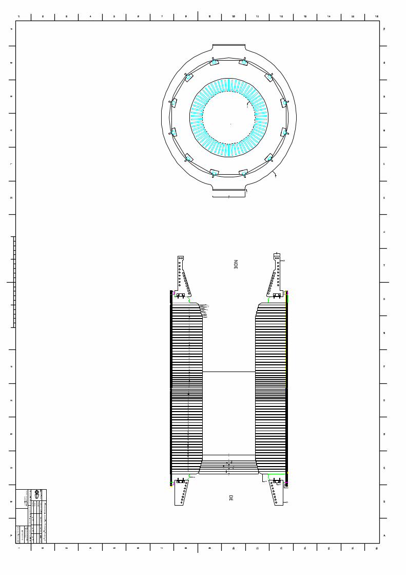
1. BALCO will be providing technical details of generator and required drawings of machine and stator bars.
2. One set of generator stator bars will consist of 132 number of bars that includes different type of top and bottom coils.
3. Vendor should provide design details, BOQ and test certificates of raw materials that will be used for manufacturing of stator bars
4. Once Order has been awarded, vendor should provide details quality assurance plan on manufacturing of stator bars
5. All the coils should be of VPI technology 6. BALCO representatives will be witnessing initial manufacturing process and final testing of new
manufactured stator bars at vendors facility 7. Detailed test reports will be submitted to BALCO by vendor, based on which final dispatch
clearance will be provided by BALCO 8. Stator bars should be delivered to BALCO in a well packed container, which will be completely
sealed one and will have provision to maintain the temperature of container at higher level compared to atmospheric condition
9. Warranty for the supplied coil will be 10 Yrs from the dated of delivery or 8 yrs from the date of installation, whichever is lower.
10. Vendor will also be doing the complete rewinding job also at BALCO site for the supplied stator bars. Separate order will be awarded for same.
11. Vendor will be keeping minimum additional coils with the supplied bars, which can be used in case of failure of any of the bars during site testing at the time of rewinding activity. Same will be taken back by vendor once rewinding work get completes.