II Harness Kit 4-Port/3-Plug Isolation Module Light System...
14
A DIVISION OR SUBSIDIARY OF DOUGLAS DYNAMICS, L.L.C. May 24, 2007 Lit. No. 28561, Rev. 04 8436, 8437-1, 8438, 8439, 8442, 8443, 27480-1, 27780, 27890, 28028, & 28400 HARNESS KIT 4-PORT ISOLATION MODULE LIGHT SYSTEM w/3-PLUG SYSTEM HARNESSES Installation Instructions CAUTION Read this document before installing the snowplow. CAUTION See your sales outlet/Web site for specific vehicle application recommendations before installation. The Kit Selection Guide/Selection List has specific vehicle and snowplow requirements.
-
Upload
nguyenthuy -
Category
Documents
-
view
213 -
download
0
Transcript of II Harness Kit 4-Port/3-Plug Isolation Module Light System...

A DIVISION OR SUBSIDIARY OF DOUGLAS DYNAMICS, L.L.C.
May 24, 2007Lit. No. 28561, Rev. 04
8436, 8437-1, 8438, 8439,8442, 8443, 27480-1, 27780,
27890, 28028, & 28400HARNESS KIT
4-PORT ISOLATION MODULELIGHT SYSTEM
w/3-PLUG SYSTEM HARNESSES
Installation Instructions
CAUTIONRead this document before installing thesnowplow.
CAUTIONSee your sales outlet/Web site for specificvehicle application recommendations beforeinstallation. The Kit Selection Guide/SelectionList has specific vehicle and snowplowrequirements.

Lit. No. 28561, Rev. 04 2 May 24, 2007
8436, 8437-1, 8438, 8439, 8442, 8443, 27480-1, 27780, 27890, 28028, 28400
SAFETY DEFINITIONS
NOTE: Indicates a situation or action that can leadto damage to your snowplow and vehicle or otherproperty. Other useful information can also bedescribed.
FUSES
The snowplow electrical and hydraulic systems containseveral automotive blade-style fuses. If a problemshould occur and fuse replacement is necessary, thereplacement fuse must be of the same type andamperage rating as the original. Installing a fuse with ahigher rating can damage the system and could start afire. Fuse replacement, including fuse ratings andlocations, is located in the Maintenance section of theOwner's Manual.
BATTERY SAFETY
CAUTIONIndicates a potentially hazardous situation that,if not avoided, may result in minor or moderateinjury. It may also be used to alert againstunsafe practices.
TORQUE CHART
Recommended Fastener Torque Chart (Ft.-Lb.)
SizeSAE
Grade 2SAE
Grade 5SAE
Grade 8
1/4-205/16-183/8-163/8-247/16-141/2-139/16-125/8-11 3/4-10 7/8-9 1-8
611192430456693150150220
91831465075110150250378583
1328 46 68 75 115 165 225 370 591 893
Metric Grade 8.8 (Ft.-Lb.)
Size TorqueSizeTorque
M 6M 8M 10
M 12M 14M 16
717 35
60 95 155
These torque values apply to fastenersexcept those noted in the instruction.
CAUTIONRead instructions before assembling. Fastenersshould be finger tight until instructed to tightenaccording to the torque chart. Use standardmethods and practices when attachingsnowplow, including proper personalprotective safety equipment.
CAUTIONBatteries normally produce explosive gaseswhich can cause personal injury. Therefore, donot allow flames, sparks or lit tobacco to comenear the battery. When charging or workingnear a battery, always cover your face andprotect your eyes, and also provide ventilation.Batteries contain sulfuric acid which burnsskin, eyes and clothing.Disconnect the battery before removing orreplacing any electrical components.
WARNINGIndicates a potentially hazardous situation that,if not avoided, could result in death or seriouspersonal injury.

Lit. No. 28561, Rev. 04 3 May 24, 2007
8436, 8437-1, 8438, 8439, 8442, 8443, 27480-1, 27780, 27890, 28028, 28400
TYPICAL SYSTEM DIAGRAM
Iso
lati
on
Mo
du
le
43
21
Park
/Tu
rn
Lam
ps
Fa
cto
ry V
eh
icle
Ha
rne
ss
Veh
icle
Head
lam
ps
Veh
icle
Batt
ery
Cab
le
Long Plug-In Harness
Sh
ort
Plu
g-I
n H
arn
ess
Veh
icle
Head
lam
ps
Park
/Tu
rn
Lam
ps
Fa
cto
ry V
eh
icle
Ha
rne
ss
Veh
icle
Lig
hti
ng
Harn
ess (
11-P
in)
Batt
ery
Batt
ery
Cab
le
RE
D
BRN/RED
BLK/ORN
RE
D
RED/GRN
Fir
e W
all
15.0
-Am
p F
use
(P
ark
/Turn
)
7.5
-Am
p F
use
(Str
aig
ht B
lade C
ontr
ol)
10.0
-Am
p F
use
(V-P
low
Contr
ol)BLK/ORN (Str)
BRN/GRN (V)
Veh
icle
Co
ntr
ol H
arn
ess (
3-P
in –
Str
aig
ht)
Veh
icle
Co
ntr
ol H
arn
ess (
7-P
in –
V-P
low
)T
o S
no
wp
low
Co
ntr
ol
To
Sw
itch
ed
Accesso
ry
BLK
BLK/ORN
Mo
tor
Rela
y
RED

Lit. No. 28561, Rev. 04 4 May 24, 2007
8436, 8437-1, 8438, 8439, 8442, 8443, 27480-1, 27780, 27890, 28028, 28400
MOTOR RELAY AND VEHICLE BATTERYCABLE INSTALLATION
NOTE: When instructed, make all snowplowbattery cable connections to the auxiliary battery,if vehicle is so equipped.
NOTE: For vehicles equipped with a tilt cab or tilthood, a service loop will be necessary whenmaking harness or cable transitions from thecab/hood to the frame. Check the cable installationfor interference by raising and lowering thecab/hood a number of times. Add anti-chafingmaterial (installer-supplied) as needed.
1. Turn off the vehicle ignition.
2. Disconnect both the NEGATIVE (–) and thePOSITIVE (+) battery cables.
3. Choose a location on the vehicle where the motorrelay will be protected from road splash and debris.Motor relay must be within 18" of the vehiclebattery. (The motor relay can be farther from thebattery if the battery cable provided with either theplug-in harness or adapter kit is longer than 22".)
NOTE: Position motor relay terminals up,horizontal or in between.
CAUTIONBatteries normally produce explosive gaseswhich can cause personal injury. Therefore, donot allow flames, sparks or lit tobacco to comenear the battery. When charging or workingnear a battery, always cover your face andprotect your eyes, and also provide ventilation.Batteries contain sulfuric acid which burnsskin, eyes and clothing.Disconnect the battery before removing orreplacing any electrical components.
CAUTIONBefore installing self-drilling screws or drillingmounting holes, check the selected mountingarea for any wires, hoses, or other obstructions.
4. Drill two 9/32" mounting holes using the motor relaymounting plate as a template. Mount the motorrelay using 1/4" x 3/4" cap screws, washers, andlocknuts.
5. Route the supplied vehicle battery cable from thegrille or bumper to the location chosen for mountingthe motor relay, avoiding any sharp edges and hotor moving parts. Cable tie only the end sectionclosest to the grille. Lengthening the vehicle batterycable may be necessary on vehicles with batterieslocated under or behind the cab. If lengtheningcables is necessary, use the same gauge wire asthe vehicle battery cable, and cover all connectionswith dual-wall heatshrink tubing to prevent shorting.
6. Attach the red wire from the vehiclebattery cable to one of the largeterminals on the motor relay. Securewith a lock washer and 5/16" nut,and tighten to a maximum of35 in-lb.
NOTE: Use dielectric grease on all electricalconnections to prevent corrosion. Fill receptaclesand lightly coat ring terminals and blades beforeassembly.
7. Route the black wire from the vehicle battery cableto the NEGATIVE (–) battery terminal. Do notconnect at this time. On vehicles with the batterieslocated under or behind the cab, connect the blackwire from the vehicle battery cable to the frameusing an existing hole or ground bolt. Prior toattaching, clean away any paint or dirt to ensure agood ground connection. The black/orange wirefrom the vehicle battery cable will connect to themating connector on the vehicle control harness.
CAUTIONOvertightening terminal attaching nuts maycause seal failure, resulting in prematurefailure of motor relay.
Red Vehicle Battery Cable
(Tighten nut to max. 35 in-lb.)

Lit. No. 28561, Rev. 04 5 May 24, 2007
8436, 8437-1, 8438, 8439, 8442, 8443, 27480-1, 27780, 27890, 28028, 28400
ISOLATION MODULE MOUNTING
The design of the Isolation Module allows it to bemounted to a variety of surfaces within the enginecompartment. The function of the Isolation Module willnot be affected by its mounting orientation.
Locate a flat surface within the engine compartment ofthe vehicle for mounting the Isolation Module. Forexample, the fire wall, fender well or radiator shroud arepossible mounting locations. If a flat surface cannot belocated, cable tie the Isolation Module to existingbrackets or harnessing. Reclosable fastener strips,cable ties, and self-drilling screws are supplied formounting the Isolation Module. When using thereclosable fastener strips, the mounting surface mustbe free of dirt and grease. If using self-drilling screws,install the screws in opposite corners if possible.
Molded Plug
Plug Cover
PLUG COVER INSTALLATION
1. Stretch the rectangular opening of the plug coverstrap over the end of the molded plug. Place theplug cover over the molded plug when snowplow isnot in use.
2. If grille plates were not provided, secure the vehiclebattery cable so it is protected when not in use andis easily retrieved for connection to the snowplow.
3. If grille plates were provided or you choose to usethem, pick the one most suitable for yourinstallation. Slide the plug into the plate.
NOTE: When choosing a location for the grilleplate, keep in mind the connection between thevehicle and the snowplow. Mounting the grilleplate too close to the center of the vehicle maymake it difficult to make your electrical connectionto the snowplow.
Isolation Module Bottom View
Screw Mounting Holes (4)
Cable Tie Mounting Holes (4)
Cable Tie Mounting Holes (4)
ReclosableFastener
Strips
CAUTIONBefore installing self-drilling screws or drillingmounting holes, check the selected mountingarea for any wires, hoses, or other obstructions.
Lit. No. 28561, Rev. 04 6 May 24, 2007
8436, 8437-1, 8438, 8439, 8442, 8443, 27480-1, 27780, 27890, 28028, 28400
VEHICLE LIGHTING AND VEHICLECONTROL HARNESS INSTALLATION
Vehicle lighting and vehicle control harnesses aredesigned to plug into one another when thesnowplow is not attached. Plug the harnessestogether before cable tying them to ensure adequatelength.
NOTE: For vehicles equipped with a tilt cab or tilthood, a service loop will be necessary when makingharness or cable transitions from the cab/hood to theframe. Check the cable installation for interferenceby raising and lowering the cab/hood a number oftimes. Add anti-chafing material (installer-supplied)as needed.
1. Route both harnesses around or through theradiator bulkhead to the Isolation Module.
2. Make the following connections:• Vehicle control harness to Port 1 on Isolation
Module.*• Vehicle lighting harness to Port 2 on Isolation
Module.*• Single-wire connector (black/orange wire) from
vehicle control harness to single-wire connector(black/orange wire) on vehicle lighting harness.
• For the 8437-1 or 27780 Harness Kit: Connectsupplied dust cover to vehicle control harness3-position plug near Isolation Module.
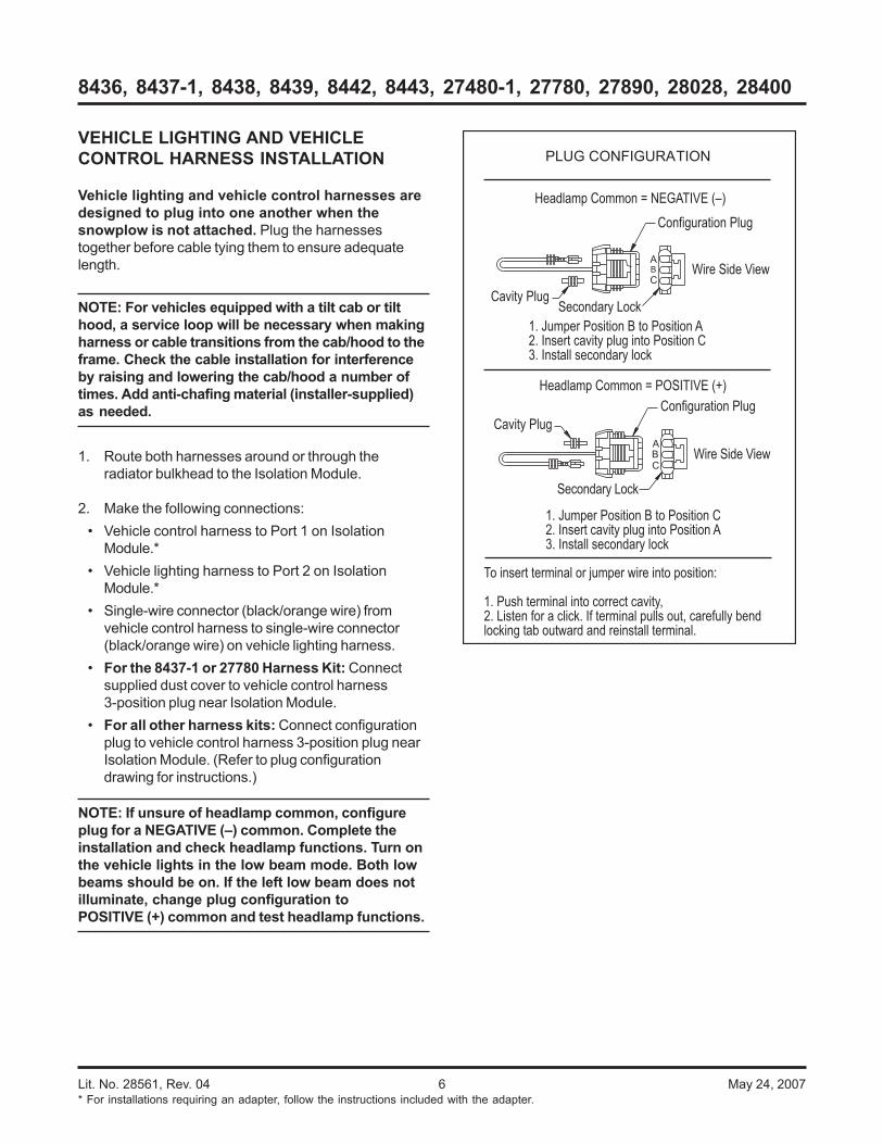
• For all other harness kits: Connect configurationplug to vehicle control harness 3-position plug nearIsolation Module. (Refer to plug configurationdrawing for instructions.)
NOTE: If unsure of headlamp common, configureplug for a NEGATIVE (–) common. Complete theinstallation and check headlamp functions. Turn onthe vehicle lights in the low beam mode. Both lowbeams should be on. If the left low beam does notilluminate, change plug configuration toPOSITIVE (+) common and test headlamp functions.
1. Jumper Position B to Position A2. Insert cavity plug into Position C3. Install secondary lock
Headlamp Common = NEGATIVE (–)
Headlamp Common = POSITIVE (+)
To insert terminal or jumper wire into position:
1. Push terminal into correct cavity,2. Listen for a click. If terminal pulls out, carefully bend locking tab outward and reinstall terminal.
Cavity Plug
Wire Side View
Configuration Plug
Secondary Lock
B
C
A
PLUG CONFIGURATION
1. Jumper Position B to Position C2. Insert cavity plug into Position A3. Install secondary lock
Configuration Plug
Cavity Plug
Wire Side View
Secondary Lock
A
CB
* For installations requiring an adapter, follow the instructions included with the adapter.

Lit. No. 28561, Rev. 04 7 May 24, 2007
8436, 8437-1, 8438, 8439, 8442, 8443, 27480-1, 27780, 27890, 28028, 28400
Red Battery Cable
Tighten to max. 35 in-lb.
Brown/Red Wire
Vehicle Control Harness
Wire from Vehicle Control Harness Straight Blade: Black/Orange V-Plow: Brown/Green
Tighten to max. 15 in-lb.
Red/GreenWire
3. Route the end of the vehicle control harness withthe white, 6-pin connector or the 10 loose terminalsto the fire wall. Route the vehicle control harnessbreakout with four wires to the motor relay.
Motor relay small terminal connections:Straight blades: brown/red and black/orangeV-plows: brown/red and brown/green
Secure wires to small terminals of motor relay with#10 lock washers and 10-32 nuts, and tighten to15 in-lb.
4. Connect the single-wire connector (black/orangewire) from the vehicle control harness breakout tothe single-wire connector (black/orange wire) fromthe vehicle battery cable. Do not cable tie theharness at this time.
5. Attach the supplied red battery cable and thered/green wire from the vehicle control harness to alarge terminal on the motor relay with a lock washerand 5/16" nut, and tighten to a maximum 35 in-lb.Route the supplied red battery cable between motorrelay terminal and POSITIVE (+) battery terminal,avoiding sharp edges and hot or moving parts. Donot make battery connection at this time.
6. On the driver side, locate anexisting hole through the fire wallfor the vehicle control harness. Ifaccess through the fire walldoes not exist, drill a 5/8"hole through the fire wall ofthe vehicle in a convenientlocation away from sharpedges, and hot or movingparts.
CAUTIONBefore installing self-drilling screws or drillingmounting holes, check the selected mountingarea for any wires, hoses, or other obstructions.
7. Remove the packing material from the end of thevehicle control harness if present. Carefully pushthe end of the harness through fire wall hole into thecab. Use a grommet, existing plug cover, or properchafing material to protect the harness where itpasses through the fire wall. Route the harness tothe selected control mounting location. If theharness has 10 socket-type terminals, follow theinstructions in the next section to attach theterminals to the connector. To mount the control,follow the instructions supplied with the control.
8. Locate an accessory wire controlled by the ignitionswitch. Acceptable accessory wires show +12Vwhen the ignition switch is on, and 0V when it is off.
9. Route the red wire from the vehicle control harnessto this location and trim away excess length.
10. Following the recommended splicing procedure, splicethe red wire into the switched accessory wire usingthe supplied parallel splices and heatshrink tubing.
CAUTIONOvertightening terminal attaching nuts maycause seal failure, resulting in prematurefailure of motor relay.

Lit. No. 28561, Rev. 04 8 May 24, 2007
8436, 8437-1, 8438, 8439, 8442, 8443, 27480-1, 27780, 27890, 28028, 28400
PLUG-IN HARNESS INSTALLATION:COLORADO/CANYON
With Headlamp DRLs
Follow instructions for all other applications starting onPage 10.
With Turn Signal DRLs
For vehicles where snowplow daytime runninglights (DRL’s) are required: 8437-1 Plug-In HarnessKit and 28555 Adapter Kit will be necessary. Follow theinstallation instructions provided with kits.
For vehicles where snowplow daytime runninglights (DRL’s) are not required: 27480-1 Plug-InHarness Kit will be necessary. The pink wire from theshort plug-in harness will not be used; cut and discardthe pink wire.
The 8437-1 Plug-In Harness and 28555 Adapter Kits andInstructions can also be used for DRL-equipped vehiclesin the United States if snowplow DRL's are desired.
Prior to installing the plug-in harnesses, you willneed to do the following: Open the convoluted tubingapproximately 6" from the 10-position connector. Locatethe purple turn signal wires and carefully pull each wireout of the harness tubing toward the 10-positionconnector.
1. Remove the headlamp connectors. Connect theplug-in harnesses to the mating connectorsremoved from the headlamps. Connect the plug-inharnesses to the mating connections at theheadlamps. Route the plug-in harnesses to theIsolation Module. Connect the driver-side plug-inharness to Port 3 on the Isolation Module. Connectpassenger-side plug-in harness to Port 4 on theIsolation Module.
NOTE: Only the short plug-in harness connects tothe vehicle parking light circuit.
2. Splice the brown wire from the short plug-in harnessinto the parking light wire at the vehicle headlampfollowing the splicing procedure.
3. On the driver side, locate the vehicle 16-positionrear lighting connector located at the lower rearcorner of the battery tray (see photo). Removal ofthe battery cover may be necessary.
4. Release the light gray connector lock, and separatethe connector halves. The rear half of connector isheld in place by a push-in plastic fender anchor;removal of this anchor will be required. With theconnector free, open the convoluted tubing, andlocate the yellow and dark green wires.
5. Splice the purple wire from the driver-side plug-inharness into the yellow wire following the splicingprocedure and trimming the purple wire as needed.
6. Splice the purple wire from the passenger-sideplug-in harness into the dark green wire followingthe splicing procedure and trimming the purple wireas needed.
7. Connect the two 16-position connector halves andreset the light gray connector lock. Reinstall thepush-in plastic fender anchor.
8. Cable tie the vehicle control harness, vehiclelighting harness, and both plug-in harnesses awayfrom any sharp, hot or moving parts. The vehiclecontrol harness and vehicle lighting harness aredesigned to plug into one another for storage.
Yellow
DarkGreen
RearLighting
Connector
Lit. No. 28561, Rev. 04 9 May 24, 2007
8436, 8437-1, 8438, 8439, 8442, 8443, 27480-1, 27780, 27890, 28028, 28400
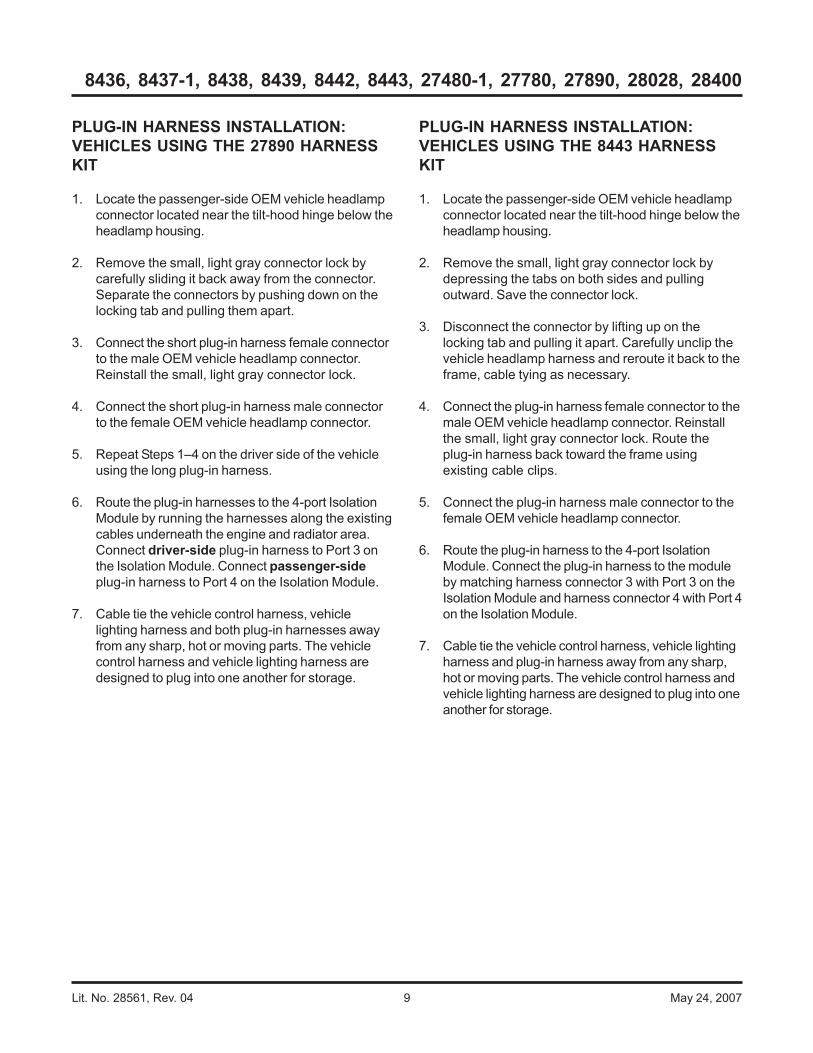
PLUG-IN HARNESS INSTALLATION:VEHICLES USING THE 27890 HARNESSKIT
1. Locate the passenger-side OEM vehicle headlampconnector located near the tilt-hood hinge below theheadlamp housing.
2. Remove the small, light gray connector lock bycarefully sliding it back away from the connector.Separate the connectors by pushing down on thelocking tab and pulling them apart.
3. Connect the short plug-in harness female connectorto the male OEM vehicle headlamp connector.Reinstall the small, light gray connector lock.
4. Connect the short plug-in harness male connectorto the female OEM vehicle headlamp connector.
5. Repeat Steps 1–4 on the driver side of the vehicleusing the long plug-in harness.
6. Route the plug-in harnesses to the 4-port IsolationModule by running the harnesses along the existingcables underneath the engine and radiator area.Connect driver-side plug-in harness to Port 3 onthe Isolation Module. Connect passenger-sideplug-in harness to Port 4 on the Isolation Module.
7. Cable tie the vehicle control harness, vehiclelighting harness and both plug-in harnesses awayfrom any sharp, hot or moving parts. The vehiclecontrol harness and vehicle lighting harness aredesigned to plug into one another for storage.
PLUG-IN HARNESS INSTALLATION:VEHICLES USING THE 8443 HARNESSKIT
1. Locate the passenger-side OEM vehicle headlampconnector located near the tilt-hood hinge below theheadlamp housing.
2. Remove the small, light gray connector lock bydepressing the tabs on both sides and pullingoutward. Save the connector lock.
3. Disconnect the connector by lifting up on thelocking tab and pulling it apart. Carefully unclip thevehicle headlamp harness and reroute it back to theframe, cable tying as necessary.
4. Connect the plug-in harness female connector to themale OEM vehicle headlamp connector. Reinstallthe small, light gray connector lock. Route theplug-in harness back toward the frame usingexisting cable clips.
5. Connect the plug-in harness male connector to thefemale OEM vehicle headlamp connector.
6. Route the plug-in harness to the 4-port IsolationModule. Connect the plug-in harness to the moduleby matching harness connector 3 with Port 3 on theIsolation Module and harness connector 4 with Port 4on the Isolation Module.
7. Cable tie the vehicle control harness, vehicle lightingharness and plug-in harness away from any sharp,hot or moving parts. The vehicle control harness andvehicle lighting harness are designed to plug into oneanother for storage.

Lit. No. 28561, Rev. 04 10 May 24, 2007
8436, 8437-1, 8438, 8439, 8442, 8443, 27480-1, 27780, 27890, 28028, 28400
* For installations requiring an adapter, follow the instructions included with the adapter.
ABC
BL
UE
Low
RE
DO
RA
NG
E
HighCommon
E
D
B
C
A
F
G
J
H
K
Blue from Molded Plug to A
Yellow from Molded Plug to J
10-PIN CONNECTOR:
BLUE – POSITION AYELLOW – POSITION J
E
D
B
C
A
F
G
J
H
K
Yellow from Molded Plug to A
Blue from Molded Plug to J
10-PIN CONNECTOR:
BLUE – POSITION JYELLOW – POSITION A
ABC
OR
AN
GE
Common
RE
DB
LU
E
LowHigh
Install wires in both connectors as shown.Install supplied secondary connectory locks.
HB-1 Headlamps(9004)
HB-5 Headlamps(9007)
PLUG-IN HARNESS INSTALLATION:ALL OTHER APPLICATIONS
NOTE: For vehicles equipped with a tilt cab or tilthood, a service loop will be necessary when makingharness or cable transitions from the cab/hood to theframe. Check the cable installation for interferenceby raising and lowering the cab/hood a number oftimes. Add anti-chafing material (installer-supplied)as needed.
1. For vehicles using the 8436 Harness Kit withthe 26641 or 28860 Adapter Kit: Refer to theillustration below, and configure both plug-inharnesses for HB-5.
For vehicles using the 28028 Harness Kit: Theplug-in harnesses connect to the headlamphousings, not the headlamp bulbs.
For all other vehicles using the 8436 HarnessKit: Refer to the previous illustration, and configureboth plug-in harnesses according to the vehicle'sheadlamp type.
2. Remove the headlamp or headlamp housingconnectors. Connect the plug-in harnesses to themating connectors removed from the headlamps orheadlamp housings.* Connect the plug-inharnesses to the mating connections at theheadlamps or headlamp housings. Route harnessesto the Isolation Module. Connect driver-side plug-inharness to Port 3 on the Isolation Module. Connectpassenger-side plug-in harness to Port 4 on theIsolation Module.
NOTE: Only the short plug-in harness connects tothe vehicle parking light and DRL circuits.
For vehicles with dedicated DRL bulbs: Splicethe pink wire from the short plug-in harness into theDRL POSITIVE (+) wire following the splicingprocedure.
For vehicles with headlamp DRLs: The pink wirefrom the short plug-in harness, if present, is notneeded. Cut and discard the pink wire.
3. If not already done during adapter installation,locate the turn signal wire on each side of thevehicle. Splice the purple wire from each plug-inharness into the signal wire on the correspondingside following the recommended splicing procedure.
4. If not already done during adapter installation, splicethe brown wire from the short plug-in harness intothe parking light wire following the splicingprocedure.
5. Cable tie the vehicle control harness, vehiclelighting harness, and both plug-in harnesses awayfrom any sharp, hot or moving parts. The vehiclecontrol harness and vehicle lighting harness aredesigned to plug into one another for storage.

Lit. No. 28561, Rev. 04 11 May 24, 2007
8436, 8437-1, 8438, 8439, 8442, 8443, 27480-1, 27780, 27890, 28028, 28400
Washer
(See Step 4)
Red Battery Cable
Vehicle Cable
Battery
ClampCap Screw
(See Step 4)
BATTERY CABLE CONNECTIONS
Top Post Batteries w/Lead Cable Ends
1. Attach the POSITIVE (+) OEM cable to the batterypost. Attach the red battery cable to the bolt in theOEM terminal with the original fastener.
2. Attach the NEGATIVE (–) OEM cable to the batterypost. Attach the black wire from the vehicle battery cableto the OEM terminal bolt with the original fastener.
Top Post Batteries w/Stamped SteelBattery Terminals
Top Post Batteries, Style One
These terminals are secured with a 6mm washer-headcap screw and nut.
1. If the cap screw is long enough for the addedthickness of the cable terminal, washer, and nut, it willnot need to be replaced, and Step 2 may be skipped.
2. Carefully lift retainer tabs (if present), and remove theshort cap screw. Insert the supplied longer cap screwthrough a 3/16" washer and into the hole in the clamp.Carefully bend the retainer tabs back into place.
3. Attach POSITIVE (+) OEM battery clamp to batterypost, and secure clamp.
4. Place the red battery cable over the end of the batteryterminal screw. If added terminal has large contactarea with the battery clamp, retain with a washer andnut. If the terminal contact area is small (i.e., terminalhole almost passes over a 6mm nut), add a washer toboth sides of the cable, and secure with a nut.
5. Connect the black wire from the vehicle batterycable and the OEM NEGATIVE (–) cable to theNEGATIVE (–) battery terminal following the sameprocedure used in Steps 1–4.
UNDER-DASH VEHICLE CONTROLHARNESS CONNECTOR PINASSIGNMENTS (Certain Models Only)
If the end of the harness already has a connector, skipto the next section. If the end of the harness has 10socket-type terminals, follow the instructions in thissection to install the terminals into the connector housing.
1. In the cab, pass the 10 socket-type terminalsthrough the vehicle harness bracket.
2. Insert each of the 10 socket-type terminals into theconnector housing. Refer to chart below.
NOTE: You will feel a snap as the terminals aresuccessfully inserted. An extraction tool isprovided for removing pin terminals if necessary.Keep this tool for future use.
3. Attach the vehicle harness bracket to the vehiclewith the supplied #8-18 x 5/8" tapping screws.Secure the connector housing to the vehicleharness bracket with #6 x 1/4" tapping screws andlock washers.
NOTE: Cable tie control harness and accessorytap away from any moving parts, brake, clutch,gas or parking brake pedals.
Wire Color Pin No. Light Blue w/ Orange Stripe 1 Blue w/ Orange Stripe 2 Black w/ White Stripe 3 Light Green 4 Light Blue 5 White w/ Yellow Stripe 6 Brown w/ Red Stripe 7 Red w/ Yellow Stripe 8 Black w/ Orange Stripe 9 Brown w/ Green Stripe 10
Insert Pins into This Side
Vehicle Harness Bracket
Connector Housing

Lit. No. 28561, Rev. 04 12 May 24, 2007
8436, 8437-1, 8438, 8439, 8442, 8443, 27480-1, 27780, 27890, 28028, 28400
Top Post Batteries, Style Two
These terminals are secured with a 6mm tapered nutand cam.
1. Make the connections to the POSITIVE (+) terminalas follows:
a. Remove cable assembly from battery post byloosening the nut. Trim plastic terminal cover asshown.
b. Carefully bend tab securing the cam upward sothe cam can be lifted off the stamped terminalafter the nut has been removed.
c. Place the red battery cable over the batteryterminal screw.
d. Slide the cam over the terminal screw and tab.Reinstall the nut.
e. Place cable assembly on battery post, align redbattery cable with the opening in the cover, andtighten nut. Close plastic terminal cover.
2. Make the connections to the NEGATIVE (–)terminal as follows:
a. Remove cable assembly from battery post byloosening the nut.
b. Carefully bend tab securing the cam upward sothe cam can be lifted off the stamped terminalafter the nut has been removed.
c. Place the black wire from the vehicle batterycable over the battery terminal screw.
Nut
CamTab
Trim marked areas
d. Slide the cam over the terminal screw and tab.Reinstall the nut.
e. Place cable assembly on battery post, andtighten nut.
Top Post Batteries, Style Three
These terminals are similar to Style Two, but do nothave a visible cam or tab.
1. Make the connections to the POSITIVE (+) terminalas follows:
a. Remove cable assembly from battery post byremoving the nut. Trim plastic terminal cover asnecessary to accommodate the red snowplowbattery cable.
b. Place the red battery cable over the batteryterminal screw and reinstall the nut.
c. Place cable assembly on battery post, align redbattery cable with the opening in the cover, andtighten nut. Close plastic terminal cover.
2. Make the connections to the NEGATIVE (–)terminal as follows:
a. Remove cable assembly from battery post byremoving the nut.
b. Place the black wire from the vehicle batterycable over the battery terminal screw andreinstall the nut.
c. Place cable assembly on battery post, andtighten nut.
Side Terminal Batteries
1. Use the furnished battery cable adapter to attachthe red battery cable to the POSITIVE (+) terminalof the battery. Position the cable, and tighten theadapter to 124–178 in-lb.
2. Connect the OEM POSITIVE (+) cable to theadapter on the battery. Position the cable, and whileholding the adapter, tighten the battery cable bolt to124–178 in-lb.
3. Connect the black wire from the vehicle batterycable and the OEM NEGATIVE (–) cable to theNEGATIVE (–) battery terminal following the sameprocedure used in Steps 1 and 2.

Lit. No. 28561, Rev. 04 13 May 24, 2007
8436, 8437-1, 8438, 8439, 8442, 8443, 27480-1, 27780, 27890, 28028, 28400
Crimp and solder each splice.
Cover the splice with heatshrink tubing. Using a hot air source, apply heat until tubing
recovers and glue can be seen around the edges. Allow tubing to cool before handling.
From park, turn, or DRL lamp
From OEM vehicle harness
From plug-inharness
Splicing Procedure
Butt Splice
5/16"
Insert wires into splice.
Heatshrink tubingGlue
RECOMMENDED SPLICING PROCEDURE
1. Locate wire to be spliced into.
2. Cut wire at least 1-1/2" from any other splice,connector, or terminal. If wires are covered by tubingor braid, remove enough of it to achieve theminimum clearance required.
3. Strip away 5/16" of the insulation from the ends ofthe wires to be spliced.
4. Slide two wires into one end of the supplied parallelsplice.
5. Place a piece of heatshrink tubing (3/16" x 1-1/4"long) over the remaining wire to be spliced. Cuttubing into 1-1/4" lengths if required.
6. Insert wire into the open end of the splice and crimpusing an appropriate crimp tool. One or two crimpsmay be necessary to ensure a good connection. Nowire strands should be visible outside of the splice.
7. Preheat a soldering tool for at least one minute tohelp promote even solder flow.
8. Apply heat to the splice. Avoid heating too close tothe insulation. Apply solder to the wires. Use justenough solder to produce an even flow through thesplice. Use rosin core solder ONLY. Do not useacid core solder.
NOTE: Avoid using an excessive amount of solderas it can result in wicking. Wicking occurs whensolder travels up the wire core. This may cause thewire to become stiff or brittle which could lead to abroken or open circuit.
9. Check circuits for continuity.
10. Cover the splice with heatshrink tubing. The tubingshould extend beyond the splice on both sides.
11. Using a hot air source, starting in the center andworking to either side, apply heat until the tubingrecovers and glue can be seen around the edges.Allow the tubing to cool before handling.
NOTE: The splices supplied will accommodate18-gauge wires as shown. For larger gauge wires,cut the wire, strip the ends 3/8" to 1/2", and twisttogether. Apply solder to the splice and coverwith heatshrink tubing.

Lit. No. 28561, Rev. 04 14 May 24, 2007
8436, 8437-1, 8438, 8439, 8442, 8443, 27480-1, 27780, 27890, 28028, 28400
The company reserves the right under its product improvement policy to change construction or design details and furnish equipment when soaltered without reference to illustrations or specifications used. This equipment manufacturer or the vehicle manufacturer may require orrecommend optional equipment for snow removal. Do not exceed vehicle ratings with a snowplow. The company offers a limited warranty forall snowplows and accessories. See separately printed page for this important information.
Printed in U.S.A.

![38+83 $*5,7(&+ ,1',$ 35,9$7( /,0,7('Quantitative Aptitude Q 1] Which one of the following cannot be the square of a natural number ? a] 30976 b] 75625 c] 28561 dl 143642 e] None of](https://static.fdocuments.us/doc/165x107/5e77fdb5d263f369d602b065/3883-57-1-3597-07-quantitative-aptitude-q-1-which-one-of.jpg)