
IHE Radiation Oncology (RO) Technical Framework Volume 1 ...€¦ · 1.7.1.5 National Electrical...
55
Copyright © 2020: IHE International, Inc. Integrating the Healthcare Enterprise IHE Radiation Oncology (RO) 5 Technical Framework Volume 1 IHE RO TF-1 10 Profiles 15 Revision 2.0 - Final Text 20 April 7, 2020 Please verify you have the most recent version of this document, which is published here. 25
Transcript of IHE Radiation Oncology (RO) Technical Framework Volume 1 ...€¦ · 1.7.1.5 National Electrical...
Copyright © 2020: IHE International, Inc.
Integrating the Healthcare Enterprise
IHE Radiation Oncology (RO) 5
Technical Framework
Volume 1 IHE RO TF-1 10
Profiles 15
Revision 2.0 - Final Text 20
April 7, 2020
Please verify you have the most recent version of this document, which is published here. 25
IHE Radiation Oncology Technical Framework, Vol. 1 (RO TF-1): Profiles ______________________________________________________________________________
______________________________________________________________________________ Rev. 2.0 – Final Text 2020-04-07 2 Copyright © 2020: IHE International, Inc.
CONTENTS
1 Introduction ................................................................................................................................ 4
1.1 Introduction to IHE ............................................................................................................. 4 1.2 Introduction to IHE Radiation Oncology Domain (RO) .................................................... 4 30 1.3 Intended Audience .............................................................................................................. 4 1.4 Prerequisites and Reference Material ................................................................................. 5
1.4.1 Actor Descriptions ....................................................................................................... 5 1.4.2 Transaction Descriptions ............................................................................................. 5 1.4.3 IHE Integration Statements.......................................................................................... 5 35
1.5 Overview of Technical Framework Volume 1 ................................................................... 5 1.6 Comment Process................................................................................................................ 6 1.7 Copyright Licenses ............................................................................................................. 6
1.7.1 Copyright of Base Standards ....................................................................................... 6 1.8 Trademark ........................................................................................................................... 7 40 1.9 Disclaimer Regarding Patent Rights ................................................................................... 7 1.10 History of Document Changes ............................................................................................ 8
2 Radiation Oncology Integration Profiles ................................................................................... 9 2.1 Dependencies among Integration Profiles .......................................................................... 9 2.2 Integration Profiles Overview ........................................................................................... 10 45
2.2.1 This section is reserved. ............................................................................................. 11 2.2.2 This section is reserved. ............................................................................................. 11
3 Basic Radiation Therapy Objects Integration Profile II (BRTO-II) ........................................ 12 3.1 Actors / Transactions ........................................................................................................ 12
3.1.1 Actor Descriptions and Actor Profile Requirements ................................................. 14 50 3.2 Basic RT Objects Integration Profile Options .................................................................. 15 3.3 BRTO II Required Actor Groupings................................................................................. 15 3.4 BRTO II Overview ........................................................................................................... 15
3.4.1 Concepts .................................................................................................................... 15 3.4.2 Use Cases ................................................................................................................... 16 55
3.5 BRTO II Security Considerations ..................................................................................... 19 3.6 BRTO II Cross Profile Considerations .............................................................................. 19
4 Multimodality Image Registration for Radiation Oncology 2018 (MMRO-III) Profile ......... 20 4.1 Actors / Transactions ........................................................................................................ 20
4.1.1 Actor Descriptions and Actor Profile Requirements ................................................. 22 60 4.2 MMRO-III Actor Options ................................................................................................. 23 4.3 MMRO-III Actor Required Groupings ............................................................................. 24 4.4 MMRO-III Overview ........................................................................................................ 24
4.4.1 Concepts .................................................................................................................... 24 4.4.2 Use Cases ................................................................................................................... 28 65
4.5 MMRO-III Security Considerations ................................................................................. 32 4.6 MMRO-III Cross Profile Considerations.......................................................................... 32
5 Treatment Planning – Plan Content Integration (TPPC) Profile .............................................. 33

IHE Radiation Oncology Technical Framework, Vol. 1 (RO TF-1): Profiles ______________________________________________________________________________
______________________________________________________________________________ Rev. 2.0 – Final Text 2020-04-07 3 Copyright © 2020: IHE International, Inc.
5.1 Actors / Transactions ........................................................................................................ 33 5.1.1 Actor Descriptions and Actor Profile Requirements .................................................. 37 70
5.2 TPPC Transaction Options ................................................................................................. 37 5.2.1 Producer / Consumer Transaction Groupings............................................................ 40
5.3 TPPC Actor Required Groupings....................................................................................... 40 5.4 TPPC Overview ................................................................................................................. 40
5.4.1 Concepts ..................................................................................................................... 41 75 5.4.2 Use Cases ................................................................................................................... 43
5.5 TPPC Security Considerations .......................................................................................... 44 5.6 TPPC Cross Profile Considerations .................................................................................. 45
Appendices .................................................................................................................................... 46 Appendix A – Actor Descriptions................................................................................................. 46 80 Appendix B – Transactions ........................................................................................................... 50 IHE Glossary ................................................................................................................................. 55
Radiation Oncology Glossary Terms ....................................................................................... 55
85

IHE Radiation Oncology Technical Framework, Vol. 1 (RO TF-1): Profiles ______________________________________________________________________________
______________________________________________________________________________ Rev. 2.0 – Final Text 2020-04-07 4 Copyright © 2020: IHE International, Inc.
1 Introduction This document, Volume 1 of the IHE Radiation Oncology (RO) Technical Framework, describes the clinical use cases, actors, content module, and transaction requirements for the Radiation Oncology profiles.
1.1 Introduction to IHE 90
Integrating the Healthcare Enterprise (IHE) is an international initiative to promote the use of standards to achieve interoperability among health information technology (HIT) systems and effective use of electronic health records (EHRs). IHE provides a forum for care providers, HIT experts and other stakeholders in several clinical and operational domains to reach consensus on standards-based solutions to critical interoperability issues. 95 The primary output of IHE is system implementation guides, called IHE profiles. IHE publishes each profile through a well-defined process of public review and Trial Implementation and gathers profiles that have reached Final Text status into an IHE Technical Framework, of which this volume is a part. For general information regarding IHE, refer to www.ihe.net. It is strongly recommended that, 100 prior to reading this volume, the reader familiarizes themselves with the concepts defined in the IHE Technical Frameworks General Introduction.
1.2 Introduction to IHE Radiation Oncology Domain (RO) In support of IHE aims, The American Association of Physicists in Medicine American Society for Radiology Oncology (AAPM) supports a multi-society Task Force and the IHE Radiation 105 Oncology Planning and Technical Committees to undertake an initiative to promote seamless connectivity and integration of radiotherapy equipment and the patient health information systems. The Task Force will include members from ASTRO, RSNA, AAPM, the American College of Radiology (ACR) and the Medical Imaging and Technology Alliance (MITA). In addition, 110 members of the International community have also been invited to participate in IHE-RO Planning and Technical Committees. The IHE-RO Task Force, in close collaboration with radiotherapy product manufacturers, will oversee development of appropriate integration profiles for radiation therapy and setup a demonstration of seamless communication among the full array of radiotherapy products. 115
1.3 Intended Audience The intended audience of IHE Technical Frameworks Volume 1 (Profiles) is:
• Those interested in integrating healthcare information systems and workflows
• IT departments of healthcare institutions
• Technical staff of vendors participating in the IHE initiative 120

IHE Radiation Oncology Technical Framework, Vol. 1 (RO TF-1): Profiles ______________________________________________________________________________
______________________________________________________________________________ Rev. 2.0 – Final Text 2020-04-07 5 Copyright © 2020: IHE International, Inc.
1.4 Prerequisites and Reference Material For more general information regarding IHE, refer to www.ihe.net. It is strongly recommended that, prior to reading this volume, the reader familiarizes themselves with the concepts defined in the IHE Technical Frameworks General Introduction. Additional reference material available includes: 125
1.4.1 Actor Descriptions Actors are information systems or components of information systems that produce, manage, or act on information associated with operational activities in the enterprise. A list of Radiation Oncology actors is available in Appendix A of this RO Volume 1 document A list of actors defined for all other domains and their brief descriptions can be found as 130 Appendix A to the IHE Technical Frameworks General Introduction.
1.4.2 Transaction Descriptions Transactions are interactions between actors that transfer the required information through standards-based messages. A list of Radiation Oncology transactions is available in Appendix B of this RO Volume 1 135 document. A list of transactions defined for all other domains, their transactions numbers, and a brief description can be found as Appendix B to the IHE Technical Frameworks General Introduction.
1.4.3 IHE Integration Statements IHE Integration Statements provide a consistent way to document high level IHE implementation 140 status in products between vendors and users. The instructions and template for IHE Integration Statements can be found as Appendix F to the IHE Technical Frameworks General Introduction. IHE also provides the IHE Product Registry (http://www.ihe.net/IHE_Product_Registry) as a resource for vendors and purchasers of HIT systems to communicate about the IHE compliance 145 of such systems. Vendors can use the Product Registry to generate and register Integration Statements.
1.5 Overview of Technical Framework Volume 1 Volume 1 is comprised of several distinct sections:
• Section 1 provides background and reference material. 150
• Section 2 presents the conventions used in this volume to define the profiles.
• Sections 3 and beyond define Radiation Oncology profiles, actors, and requirements in detail.
The appendices in Volume 1 provide clarification of uses cases or other details.
IHE Radiation Oncology Technical Framework, Vol. 1 (RO TF-1): Profiles ______________________________________________________________________________
______________________________________________________________________________ Rev. 2.0 – Final Text 2020-04-07 6 Copyright © 2020: IHE International, Inc.
A glossary of terms and acronyms used in the IHE Technical Framework is provided in 155 Appendix D to the IHE Technical Frameworks General Introduction. Radiation Oncology Glossary terms are available in this document here.
1.6 Comment Process AAPM welcomes comments on this document and the IHE-RO initiative. They should be submitted at http://www.ihe.net/Radiation_Oncology_Public_Comments or to: 160
Jill I. Moton, MBA Program Manager American Association of Physicists in Medicine (AAPM) 1631 Prince Street Alexandria, VA [email protected] 165
1.7 Copyright Licenses IHE International hereby grants to each Member Organization, and to any other user of these documents, an irrevocable, worldwide, perpetual, royalty-free, nontransferable, nonexclusive, non-sublicensable license under its copyrights in any IHE profiles and Technical Framework documents, as well as any additional copyrighted materials that will be owned by IHE 170 International and will be made available for use by Member Organizations, to reproduce and distribute (in any and all print, electronic or other means of reproduction, storage or transmission) such IHE Technical Documents. The licenses covered by this Copyright License are only to those copyrights owned or controlled by IHE International itself. If parts of the Technical Framework are included in products that also 175 include materials owned or controlled by other parties, licenses to use those products are beyond the scope of this IHE document and would have to be obtained from that other party.
1.7.1 Copyright of Base Standards IHE technical documents refer to and make use of a number of standards developed and published by several standards development organizations. All rights for their respective base 180 standards are reserved by these organizations. This agreement does not supersede any copyright provisions applicable to such base standards. Copyright license information for frequently referenced base standards is provided below.
1.7.1.1 DICOM (Digital Imaging and Communications in Medicine) DICOM® is the registered trademark of the National Electrical Manufacturers Association for its 185 standards publications relating to digital communications of medical information.
1.7.1.2 HL7 (Health Level Seven) HL7®, Health Level Seven®, CDA®, FHIR®, and the FHIR [FLAME DESIGN] ® are registered trademarks of Health Level Seven International.
IHE Radiation Oncology Technical Framework, Vol. 1 (RO TF-1): Profiles ______________________________________________________________________________
______________________________________________________________________________ Rev. 2.0 – Final Text 2020-04-07 7 Copyright © 2020: IHE International, Inc.
Health Level Seven, Inc. has granted permission to IHE to reproduce tables from the HL7 190 standard. The HL7 tables in this document are copyrighted by Health Level Seven, Inc. All rights reserved. Material drawn from these documents is credited where used.
1.7.1.3 LOINC (Logical Observation Identifiers Names and Codes) LOINC® is registered United States trademarks of Regenstrief Institute, Inc.
1.7.1.4 SNOMED CT (Systematized Nomenclature of Medicine -- Clinical Terms) 195 Some IHE Profiles incorporate SNOMED® CT, which is used by permission of the International Health Terminology Standards Development Organisation. SNOMED CT© was originally created by the College of American Pathologists. SNOMED CT is a registered trademark of the International Health Terminology Standards Development Organisation, all rights reserved.
1.7.1.5 National Electrical Manufacturers Association (NEMA) 200 The National Electrical Manufacturers Association (NEMA) has granted permission to IHE to incorporate portions of the DICOM standard. Material drawn from these documents is credited where used.
1.8 Trademark IHE® and the IHE logo are trademarks of the Healthcare Information Management Systems 205 Society in the United States and trademarks of IHE Europe in the European Community. They may only be used with the written consent of the IHE International Board Operations Committee, which may be given to a Member Organization in broad terms for any use that is consistent with the IHE mission and operating principles.
1.9 Disclaimer Regarding Patent Rights 210
Attention is called to the possibility that implementation of the specifications in this document may require use of subject matter covered by patent rights. By publication of this document, no position is taken with respect to the existence or validity of any patent rights in connection therewith. IHE International is not responsible for identifying Necessary Patent Claims for which a license may be required, for conducting inquiries into the legal validity or scope of Patents 215 Claims or determining whether any licensing terms or conditions provided in connection with submission of a Letter of Assurance, if any, or in any licensing agreements are reasonable or non-discriminatory. Users of the specifications in this document are expressly advised that determination of the validity of any patent rights, and the risk of infringement of such rights, is entirely their own responsibility. Further information about the IHE International patent 220 disclosure process including links to forms for making disclosures is available at http://www.ihe.net/Patent_Disclosure_Process. Please address questions about the patent disclosure process to the secretary of the IHE International Board: [email protected].

IHE Radiation Oncology Technical Framework, Vol. 1 (RO TF-1): Profiles ______________________________________________________________________________
______________________________________________________________________________ Rev. 2.0 – Final Text 2020-04-07 8 Copyright © 2020: IHE International, Inc.
1.10 History of Document Changes 225
This section provides a brief summary of changes and additions to this document.
Date Document Revision
Change Summary
2007 Initiated the IHE Radiation Oncology Technical Frameworks with the Basic Radiation Therapy Objects Integration Profile (BRTO).
2011 Updated the front matter sections of Volumes 1 and 2 of the IHE Radiation Oncology Technical Frameworks to be consistent with newly released domain-wide sections.
2014 Updated Volumes 1 and 2 of the IHE Radiation Oncology Technical Frameworks to include approved 2013 change proposals and technical frameworks formatting changes.
2020 2.0 Updated Volumes 1 and 2 of the IHE Radiation Oncology Technical Frameworks to include profiles voted to Final Text Also initiated a Volume 3 to include DICOM Content Modules. Updated format of Section 1 to match current released Volume 1 template.
2

IHE Radiation Oncology Technical Framework, Vol. 1 (RO TF-1): Profiles ______________________________________________________________________________
______________________________________________________________________________ Rev. 2.0 – Final Text 2020-04-07 9 Copyright © 2020: IHE International, Inc.
2 Radiation Oncology Integration Profiles IHE Radiation Oncology Integration Profiles (Figure 2-1), offer a common language that 230 healthcare professionals and vendors can use to discuss integration needs of healthcare enterprises and the integration capabilities of information systems in precise terms. Integration Profiles specify implementations of standards that are designed to meet identified clinical needs. They enable users and vendors to state which IHE capabilities they require or provide, by reference to the detailed specifications of the IHE Radiation Oncology Technical Framework. 235 Integration profiles are defined in terms of IHE actors and transactions. Actors (see RO TF-1: Appendix A) are information systems or components of information systems that produce, manage, or act on information associated with clinical and operational activities in the enterprise. Transactions (see RO TF-1: Appendix B) are interactions between actors that communicate the required information through standards-based messages. 240 Vendor products support an Integration Profile by implementing the appropriate actor(s) and transactions. A given product may implement more than one actor and more than one integration profile. Some profiles are content only and are vehicles for defining how attributes and values are grouped to give useful backing to the other, workflow-based profiles.
245
Figure 2-1: IHE Radiation Oncology Integration Profiles
2.1 Dependencies among Integration Profiles Dependencies among IHE Integration Profiles exist when implementation of one integration 250 profile is a prerequisite for achieving the functionality defined in another integration profile. Figure 2-1 provides a graphical view of the dependencies among IHE Radiation Oncology Integration Profiles and between IHE RO Integration Profiles and Integration Profiles from other domains (such as Radiology). The arrows in the figure point from a given integration profile to the integration profile(s) upon which it depends. Table 2.1-1 defines these dependencies in 255 tabular form.
Basic Radiation Therapy Objects II(establishes baseline interoperability for simple RT objects from image
acquisition through dose display. )
Treatment Planning - Plan Content(A profile that describes the attribute and value makeup of external radiation
beams in terms that are consistent and grouped by treatment technique )
Multi-Modality Image Registration for Radiation Oncology 2018(specifies communications between systems creating and registering
image sets, encompassing the spatial registration process)

IHE Radiation Oncology Technical Framework, Vol. 1 (RO TF-1): Profiles ______________________________________________________________________________
______________________________________________________________________________ Rev. 2.0 – Final Text 2020-04-07 10 Copyright © 2020: IHE International, Inc.
Some dependencies require that an actor supporting one profile be grouped with one or more actors supporting other integration profiles. For example (see the ITI TF), Enterprise User Authentication (EUA) requires that different actors be grouped with the Time Client Actor that participates in the Consistent Time (CT) Integration Profile. The dependency exists because 260 EUA Actors must refer to consistent time in order to function properly.
Table 2.1-1: Integration Profiles Dependencies Integration Profile Depends on Dependency Type Purpose
Basic Radiation Therapy Objects II
Scheduled Workflow
Acquisition Modality Image Storage (RAD-8)
CT Images will be stored in the archive in
accordance with the referenced transaction
Multimodality Image Registration for Radiation Oncology 2018
Scheduled Workflow
Acquisition Modality Image Storage (RAD-8)
Modality Images (CT, MR, PT… ) will be stored in the archive in accordance with the referenced transaction
Multimodality Image Registration for Radiation Oncology 2018
Scheduled Workflow
Creator Images Stored (RAD-18) Created Images (CT, MR, PT… ) will be stored in the archive in accordance with the referenced transaction
Multimodality Image Registration for Radiation Oncology 2018
Basic Radiation Therapy Objects
II
Dose Storage [RO-5] RT Dose will be stored in the archive in accordance
with the referenced transaction
To support a dependent profile, an actor must implement all required transactions in the prerequisite profiles in addition to those in the dependent profile. In some cases, the prerequisite 265 is that the actor selects any one of a given set of profiles.
2.2 Integration Profiles Overview In this document, each IHE Integration Profile is defined by:
• The IHE actors involved
• The specific set of IHE transactions exchanged by each IHE actor. 270 Some supplements to the Technical Framework are Content Profiles, their main effect is to add consistent sets of attribute descriptions to Volume 3 of the Technical Framework. These requirements are presented in the form of a table of transactions required for each actor supporting the Integration Profile. Actors supporting multiple Integration Profiles are required to support all the required transactions of each Integration Profile supported. When an Integration 275 Profile depends upon another Integration Profile, the transactions required for the dependent Integration Profile have not been included in the table. Note that IHE Integration Profiles are not statements of conformance to standards, and IHE is not a certifying body. Users should continue to request that vendors provide statements of their conformance to standards issued by relevant standards bodies, such as HL7 and DICOM. 280 Standards conformance is a prerequisite for vendors adopting IHE Integration Profiles.

IHE Radiation Oncology Technical Framework, Vol. 1 (RO TF-1): Profiles ______________________________________________________________________________
______________________________________________________________________________ Rev. 2.0 – Final Text 2020-04-07 11 Copyright © 2020: IHE International, Inc.
Also note that there are critical requirements for any successful integration project that IHE cannot address. Successfully integrating systems still requires a project plan that minimizes disruptions and describes fail-safe strategies, specific and mutually understood performance expectations, well-defined user interface requirements, clearly identified systems limitations, 285 detailed cost objectives, plans for maintenance and support, etc.
2.2.1 This section is reserved.
2.2.2 This section is reserved.

IHE Radiation Oncology Technical Framework, Vol. 1 (RO TF-1): Profiles ______________________________________________________________________________
______________________________________________________________________________ Rev. 2.0 – Final Text 2020-04-07 12 Copyright © 2020: IHE International, Inc.
3 Basic Radiation Therapy Objects Integration Profile II (BRTO-II) The Basic Radiation Therapy Objects II Integration Profile involves the flow of DICOM®1 290 images and treatment planning data, from CT scan through dose display, for 3D conformal, external beam radiation therapy. Detailed plan content for different types of delivery are specified in separate profiles. The emphasis for this integration profile is on reducing ambiguity and facilitating basic interoperability in the exchange of DICOM RT objects. The BRTO II Profile has the following implications: 295
• All related DICOM objects (CT images, RT Structure Sets, RT Plans, and RT Doses) are required to be in the same frame of reference and have the same Frame of Reference UID.
• The orientation of images, structures, plans, and doses must be consistent, with the exception that head-first/feet-first directions may be altered between scans and treatment 300 delivery.
The profile also addresses some capabilities that have been shown to affect interoperability of applications during the Radiation Oncology Treatment Planning Process. The issues addressed include the following:
• Variable Slice Spacing – As above, CT devices may produce image datasets with 305 different slice spacing within a single series. All applications must be able to accept such datasets.
• If a Contourer creates an RT Structure Set based on a resampled image set, the Contourer must be able to store the resampled image
• Dose Grid Spacing – Many applications are capable of producing RT Dose objects with 310 different spacing in the X, Y, and Z dimensions. This implies that dose grids are regular inplane, but not guaranteed to have equal row and column spacing. Z-spacing (slice spacing) can be different from the X and Y spacing. This profile requires equidistant Z-spacing for the RT Dose.
3.1 Actors / Transactions 315
Table 3.1-1 lists the transactions for each actor directly involved in the Basic Radiation Therapy Objects II Integration Profile. In order to claim support of this Integration Profile, an implementation must perform the required transactions (labeled “R”). A complete list of options defined by this Integration Profile and that implementations may choose to support is listed in IHE RO TF-1: 3.2. 320
1 DICOM is the registered trademark of the National Electrical Manufacturers Association for its standards publications relating to digital communications of medical information.

IHE Radiation Oncology Technical Framework, Vol. 1 (RO TF-1): Profiles ______________________________________________________________________________
______________________________________________________________________________ Rev. 2.0 – Final Text 2020-04-07 13 Copyright © 2020: IHE International, Inc.
Table 3.1-1: Basic RT Objects Integration Profile II - Actors and Transactions Actors Transactions Optionality Section
Archive Single/Contoured Series Image Retrieval [RO-1] R RO TF-2: 3.1
Structure Set Storage [RO-2] R RO TF-2: 3.2
Off-slice Structure Set Storage [RO-BRTO-II-1] R RO TF-2: 3.3
Dosimetric Plan Storage [RO-4] R RO TF-2: 3.4
Dose Storage [RO-BRTO-II-5] R RO TF-2: 3.5
DVH Dose Storage [RO-BRTO-II-3] R RO TF-2: 3.6
Structure Set Retrieval [RO-7] R RO TF-2: 3.7
Off-slice Structure Set Retrieval [RO-BRTO-II-2] R RO TF-2: 3.8
Geometric Plan Retrieval [RO-8] R RO TF-2: 3.9
Dosimetric Plan Retrieval [RO-9] R RO TF-2: 3.10
Dose Retrieval [RO-BRTO-II-6] R RO TF-2: 3.11
DVH Dose Retrieval [RO-BRTO-II-4] R RO TF-2: 3.12
Resampled/Combined CT Series Storage [RO-11] R RO TF-2: 3.13
Contourer Single/Contoured Series Image Retrieval [RO-1] R RO TF-2: 3.1
Structure Set Storage [RO-2] R RO TF-2: 3.2
Off-slice Structure Set Storage [RO-BRTO-II-1] O RO TF-2: 3.3
Structure Set Retrieval [RO-7] O RO TF-2: 3.7
Off-slice Structure Set Retrieval [RO-BRTO-II-2] O RO TF-2: 3.8
Resampled/Combined CT Series Storage [RO-11] O RO TF-2: 3.13
Dosimetric Planner
Dosimetric Plan Storage [RO-4] R RO TF-2: 3.4
Dose Storage [RO-BRTO-II-5] R RO TF-2: 3.5
DVH Dose Storage [RO-BRTO-II-3] O RO TF-2: 3.6
Structure Set Storage [RO-2] R RO TF-2: 3.2
Off-slice Structure Set Storage [RO-BRTO-II-1] O RO TF-2: 3.3
Geometric Plan Retrieval [RO-8] O RO TF-2: 3.9
Structure Set Retrieval [RO-7] R RO TF-2: 3.7
Off-slice Structure Set Retrieval [RO-BRTO-II-2] O RO TF-2: 3.8
Single/Contoured Series Image Retrieval [RO-1] R RO TF-2: 3.1
Resampled/Combined CT Series Storage [RO-11] O RO TF-2: 3.13
Dose Displayer Dose Retrieval [RO-BRTO-II-6] R RO TF-2: 3.11
DVH Dose Retrieval [RO-BRTO-II-4] O RO TF-2: 3.12
Dosimetric Plan Retrieval [RO-9] R RO TF-2: 3.10
Structure Set Retrieval [RO-7] R RO TF-2: 3.7
Off-slice Structure Set Retrieval [RO-BRTO-II-2] O RO TF-2: 3.8
Single/Contoured Series Image Retrieval [RO-1] R RO TF-2: 3.1
325

IHE Radiation Oncology Technical Framework, Vol. 1 (RO TF-1): Profiles ______________________________________________________________________________
______________________________________________________________________________ Rev. 2.0 – Final Text 2020-04-07 14 Copyright © 2020: IHE International, Inc.
Figure 3.1-1 shows the actors directly involved in the Basic RT Objects II Integration Profile and the relevant transactions between them. Other actors that may be indirectly involved due to their participation in Scheduled Workflow are not necessarily shown.
Figure 3.1-1: Basic RT Objects Actor Diagram 330
3.1.1 Actor Descriptions and Actor Profile Requirements Most requirements are documented in Transactions (Volume 2) and Content Modules (Volume 3). This section documents any additional requirements on profile’s actors. Acquisition Modality – A system that acquires and creates medical images while a patient is present, e.g., a Computed Tomography scanner or Nuclear Medicine camera. A modality may 335 also create other evidence objects such as Grayscale Softcopy Presentation States for the consistent viewing of images or Evidence Documents containing measurements. Archive – A system that provides long term storage of evidence objects such as images, presentation states, Key Image Notes and Evidence Documents. Contourer – A system that consumes one or more CT image series and creates an RT Structure 340 Set. If the Contourer consumes multiple CT image series or has an internal requirement for
IHE Radiation Oncology Technical Framework, Vol. 1 (RO TF-1): Profiles ______________________________________________________________________________
______________________________________________________________________________ Rev. 2.0 – Final Text 2020-04-07 15 Copyright © 2020: IHE International, Inc.
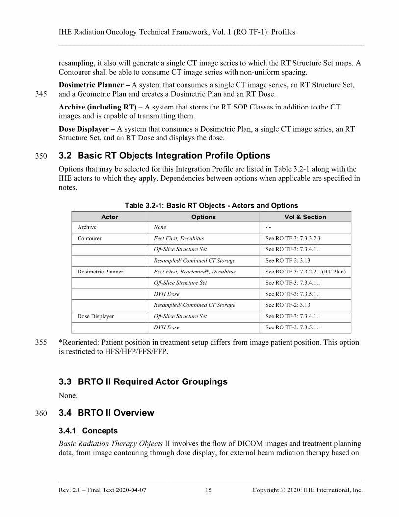
resampling, it also will generate a single CT image series to which the RT Structure Set maps. A Contourer shall be able to consume CT image series with non-uniform spacing. Dosimetric Planner – A system that consumes a single CT image series, an RT Structure Set, and a Geometric Plan and creates a Dosimetric Plan and an RT Dose. 345 Archive (including RT) – A system that stores the RT SOP Classes in addition to the CT images and is capable of transmitting them. Dose Displayer – A system that consumes a Dosimetric Plan, a single CT image series, an RT Structure Set, and an RT Dose and displays the dose.
3.2 Basic RT Objects Integration Profile Options 350
Options that may be selected for this Integration Profile are listed in Table 3.2-1 along with the IHE actors to which they apply. Dependencies between options when applicable are specified in notes.
Table 3.2-1: Basic RT Objects - Actors and Options Actor Options Vol & Section
Archive None - -
Contourer Feet First, Decubitus See RO TF-3: 7.3.3.2.3
Off-Slice Structure Set See RO TF-3: 7.3.4.1.1
Resampled/ Combined CT Storage See RO TF-2: 3.13
Dosimetric Planner Feet First, Reoriented*, Decubitus See RO TF-3: 7.3.2.2.1 (RT Plan)
Off-Slice Structure Set See RO TF-3: 7.3.4.1.1
DVH Dose See RO TF-3: 7.3.5.1.1
Resampled/ Combined CT Storage See RO TF-2: 3.13
Dose Displayer Off-Slice Structure Set See RO TF-3: 7.3.4.1.1
DVH Dose See RO TF-3: 7.3.5.1.1
*Reoriented: Patient position in treatment setup differs from image patient position. This option 355 is restricted to HFS/HFP/FFS/FFP.
3.3 BRTO II Required Actor Groupings None.
3.4 BRTO II Overview 360
3.4.1 Concepts Basic Radiation Therapy Objects II involves the flow of DICOM images and treatment planning data, from image contouring through dose display, for external beam radiation therapy based on

IHE Radiation Oncology Technical Framework, Vol. 1 (RO TF-1): Profiles ______________________________________________________________________________
______________________________________________________________________________ Rev. 2.0 – Final Text 2020-04-07 16 Copyright © 2020: IHE International, Inc.
volumetric images. The emphasis for this Integration Profile is on reducing ambiguity and facilitating basic interoperability in the exchange of DICOM RT objects. 365 Structures used within the scope of this profile may be drawn on a CT slice (on-slice contour) or optionally between the CT slices (off-slice contour). Off-slice contouring may be used to represent more detailed structural information. Such information may come from other imaging modalities or from processing CT-derived structures.
3.4.2 Use Cases 370
Figure 3.4.2-1: Basic Process Flow in Basic RT Objects Profile
3.4.2.1 Use Case #1: Segmentation of Treatment-Relevant Structures At the beginning of the planning process for a Radiation Therapy, treatment-relevant structures have to be contoured based on an image data set. These structures shall be persisted in an RT 375 Structure Set.
3.4.2.1.1 Segmentation of Treatment-Relevant Structures Use Case Description The user wants to create a structure object containing the target volume(s) and organs at risk relevant for a treatment planning. These objects are contoured on an initial CT image set. When the contouring is finished the structure object will be persisted in an archive. 380

IHE Radiation Oncology Technical Framework, Vol. 1 (RO TF-1): Profiles ______________________________________________________________________________
______________________________________________________________________________ Rev. 2.0 – Final Text 2020-04-07 17 Copyright © 2020: IHE International, Inc.
3.4.2.1.2 Segmentation of Treatment-Relevant Structures Process Flow
Figure 3.4.2.1.2-1: Segmentation of Treatment-Relevant Structures Process Flow in
BRTO-II Profile 385
Pre-conditions: The initial image set is available. Main Flow: The initial image set is retrieved by the contouring system, which sends the RT Structure Set back to the archiving system. 390 Post-conditions: The RT Structure Set is archived.
3.4.2.2 Use Case #2: Treatment Planning Based on Segmented Objects Based on the previously contoured structures a treatment planning is performed. As a result an RT Plan and an RT Dose object are persisted, representing the planning result. 395
3.4.2.2.1 Treatment Planning Based on Segmented Objects Use Case Description The user wants to create a treatment plan for the patient based on previously contoured object definitions. These object definitions and referenced image sets are retrieved by the Treatment Planning System (TPS) acting as a Dosimetric Planner. The user creates an appropriate plan for treatment. The content of such a plan is beyond the scope of this profile. The resulting RT Plan 400 and a corresponding dose distribution shall be saved back to an archive. Optionally the Dose Volume Histogram (DVH) is saved back to the archive.
3.4.2.2.2Treatment Planning Based on Segmented Objects Process Flow
Single/Contoured Series CT Retrieval [RO-1]
Resampled/Combined CT Series Storage [RO-11]
Single/Contoured Series CT Retrieval [RO-1]
Off-slice Structure Set Storage [RO-BRTO-II-1]
Structure Set Storage [RO-2]
:Archive :Contourer
Version 1.0 2016-01-27

IHE Radiation Oncology Technical Framework, Vol. 1 (RO TF-1): Profiles ______________________________________________________________________________
______________________________________________________________________________ Rev. 2.0 – Final Text 2020-04-07 18 Copyright © 2020: IHE International, Inc.
405
Figure 3.4.2.2.2-1: Treatment Planning Based on Segmented Objects Process Flow in BRTO-II Profile
Pre-conditions: The initial image set and RT Structure Set are available. 410 Main Flow: The initial image set(s) and RT Structure Set are retrieved by the Treatment Planning System (TPS). The user creates RT Plan on the TPS and calculates the dose. The TPS send the results sends back to the archiving system. Post-conditions: 415 The RT Plan and RT Dose objects are archived.
3.4.2.3 Use Case #3: Dose Display of Treatment Planning Results The result of previous treatment planning is shown to the user.
3.4.2.3.1 Dose Display of Treatment Planning Results Use Case Description The user wants to inspect the result of previous treatment planning. The created object 420 definitions including the dose distribution are retrieved by the Dose Displayer and shown to the user. Optionally the Dose Volume Histogram (DVH) is imported and displayed.
Dosimetric Planner
DVH Dose Storage [RO-BRTO-II-3]
Geometric Plan Retrieval [RO-8]
Structure Set Retrieval [RO-7]
Single/Contoured Series CT Retrieval [RO-1]
Off-slice Structure Set Retrieval [RO-BRTO-II-2]
:Archive
Structure Set Storage [RO-2]
Off-slice Structure Set Storage [RO-BRTO-II-1]
Dose Storage [RO-BRTO-II-5]
Dosimetric Plan Storage [RO-4]
Version 1.2 2018-02-

IHE Radiation Oncology Technical Framework, Vol. 1 (RO TF-1): Profiles ______________________________________________________________________________
______________________________________________________________________________ Rev. 2.0 – Final Text 2020-04-07 19 Copyright © 2020: IHE International, Inc.
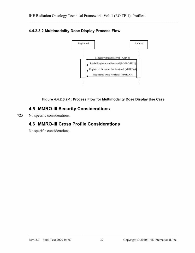
3.4.2.3.2 Dose Display of Treatment Planning Results Process Flow
425 Figure 3.4.2.3.2-1: Dose Display of Treatment Planning Results Process Flow in BRTO-II
Profile
Pre-conditions: The planning CT image set, RT Structure Set, RT Plan and RT Dose are available. 430 Main Flow: The planning CT image set, RT Structure Set, RT Plan and RT Dose are retrieved by the Dose Displayer, which shows the given information to the user. Post-conditions: None. 435
3.5 BRTO II Security Considerations There are no explicit security considerations in this profile.
3.6 BRTO II Cross Profile Considerations Segmentation requirements of this profile are expected to be referenced by other profiles. 440
DVH Dose Retrieval [RO-BRTO-II-4]
Dosimetric Plan Retrieval [RO-9]
Dose Retrieval [RO-BRTO-II-6]
Off-slice Structure Set Retrieval [RO-BRTO-II-1]
Structure Set Retrieval [RO-7]
Archive Dose Viewer
Single/Contoured Series CT Retrieval [RO-1] Version 1.2 2018-02-07

IHE Radiation Oncology Technical Framework, Vol. 1 (RO TF-1): Profiles ______________________________________________________________________________
______________________________________________________________________________ Rev. 2.0 – Final Text 2020-04-07 20 Copyright © 2020: IHE International, Inc.
4 Multimodality Image Registration for Radiation Oncology 2018 (MMRO-III) Profile
This Integration Profile specifies how images, RT Structure Sets, RT Doses, and associated spatial registration information can be exchanged, stored, processed and displayed. For a display workstation, it is essential that a workstation correctly identifies the corresponding image sets, 445 matches data from single-slice and multi-slice datasets, matches coordinate systems, and performs spatial translations. The use of relevant DICOM objects (Spatial Registration) is clarified and constrained in order to avoid misinterpretation. The Multimodality Image Registration for Radiation Oncology 2018 (MMRO-III) Profile focuses on content for image registration and does not define a registration workflow. Such 450 workflow could be managed by using mechanisms described in the Post-Acquisition Workflow Integration Profile (see RAD TF-1: 12). The MMRO-III Profile currently only handles rigid registration. Deformable registration will be addressed in a separate Profile in the future. The MMRO-III Profile does not specify the use of quantification methods for the image data that 455 are created or displayed. In particular, interoperability for PET Standard Uptake Values (SUV) is considered a relevant future work item for IHE. Note that vendors may wish to provide SUV capability even though not required under this Profile. The MMRO-III Profile has implicit limitations imposed by its dependency on the IHE-RO BRTO-II Profile. The most significant of these are listed here: 460
• Only the following patient orientations {HFS, HFP, FFS, FFP} shall be considered to be within the scope of this profile. Actors participating in this profile may be capable of handling additional orientations (decubitus), but such orientations will not be tested with this profile.
The primary image set shall be of modality CT or MR. The image orientation of the “primary” 465 shall be transversal. The “secondary” image set shall be a rectilinear, not skewed, not sheared image set of modality CT, MR or PET. Their image orientation shall be one of the cardinal planes +/-30°. Other image orientations are out of scope of this profile. RT Dose shall be in the Registered Frame of Reference, e.g., in the same Frame of Reference as its referenced image set. 470
4.1 Actors / Transactions Figure 4.1-1 shows the actors directly involved in the MMRO-III Profile and the relevant transactions between them. If needed for context, other actors that may be indirectly involved due to their participation in other related profiles are shown in dotted lines. Actors which have a mandatory grouping are shown in conjoined boxes. 475 This Profile uses the MMRO Registered Contourer Actor, which must be compatible with RT Structure Set objects created by the BRTO-II Profile Contourer Actor.

IHE Radiation Oncology Technical Framework, Vol. 1 (RO TF-1): Profiles ______________________________________________________________________________
______________________________________________________________________________ Rev. 2.0 – Final Text 2020-04-07 21 Copyright © 2020: IHE International, Inc.
480
Figure 4.1-1: MMRO-III Actor Diagram
Table 4.1-1 lists the transactions for each actor directly involved in the MMRO-III Profile. In order to claim support of this Profile, an implementation of an actor must perform the required transactions (labeled “R”) and may support the optional transactions (labeled “O”). Actor groupings are further described in Section 4.3. 485 490
Registrator
Registered Display
Registered Dose Display
Registered Contourer
Archive
Modality Images Stored [RAD-8] Registered Structure Set Retrieval [RO-MMRO-2] Spatial Registration Retrieval [RO-MMRO-5]
Modality Images Stored [RAD-8] Registered Structure Set Retrieval [RO-MMRO-2] Registered Dose Retrieval [RO-MMRO-3] Spatial Registration Retrieval [RO-MMRO-5]
Modality Images Stored [RAD-8] Registered Structure Set Retrieval [RO-MMRO-2] Spatial Registration Retrieval [RO-MMRO-5]
Registered Structure Set Storage [RO-MMRO-1}
Modality Images Stored [RAD-8] Spatial Registration Retrieval [RO-MMRO-5]
Spatial Registration Storage [RO-MMRO-4]
Creator Images Stored

IHE Radiation Oncology Technical Framework, Vol. 1 (RO TF-1): Profiles ______________________________________________________________________________
______________________________________________________________________________ Rev. 2.0 – Final Text 2020-04-07 22 Copyright © 2020: IHE International, Inc.
Table 4.1-1: MMRO-III Profile – Actors and Transactions Actors Transactions Optionality Section in
Vol. 2 Archive Modality Images Stored R RAD 4.8
Creator Images Stored R RAD 4.18 Registered Structure Set Storage R MMRO-3 Spatial Registration-III Storage R MMRO-III-1 Spatial Registration-III Retrieval R MMRO-III-2 Registered Dose Retrieval R MMRO-5 Registered Structure Set Retrieval R MMRO-4
Registrator Modality Images Stored R RAD 4.8 Creator Images Stored O RAD 4.18 Spatial Registration-III Retrieval O MMRO-III-2 Spatial Registration-III Storage R MMRO-III-1
Registered Contourer Modality Images Stored R RAD 4.8 Registered Structure Set Storage R MMRO-3 Registered Structure Set Retrieval R MMRO-4 Spatial Registration-III Retrieval R MMRO-III-2
Registered Display Modality Images Stored R RAD 4.8 Registered Structure Set Retrieval R MMRO-4 Spatial Registration-III Retrieval R MMRO-III-2
Registered Dose Display Modality Images Stored R RAD 4.8 Registered Structure Set Retrieval R MMRO-4 Registered Dose Retrieval R MMRO-5 Spatial Registration-III Retrieval R MMRO-III-2
4.1.1 Actor Descriptions and Actor Profile Requirements No special requirements 495

IHE Radiation Oncology Technical Framework, Vol. 1 (RO TF-1): Profiles ______________________________________________________________________________
______________________________________________________________________________ Rev. 2.0 – Final Text 2020-04-07 23 Copyright © 2020: IHE International, Inc.
4.2 MMRO-III Actor Options Options that may be selected for this Profile are listed in the Table 4.2-1 along with the actors to which they apply. Dependencies between options when applicable are specified in notes.
Table 4.2-1: MMRO-III - Actors and Options 500 Actor Options Volume & Section
Archive No options defined - - Registrator Creator Images Stored RAD 4.18
Spatial Registration-III Retrieval MMRO-III-2 Registered Contourer No options defined - - Registered Display No options defined - - Registered Dose Display No options defined - -

IHE Radiation Oncology Technical Framework, Vol. 1 (RO TF-1): Profiles ______________________________________________________________________________
______________________________________________________________________________ Rev. 2.0 – Final Text 2020-04-07 24 Copyright © 2020: IHE International, Inc.
4.3 MMRO-III Actor Required Groupings None.
4.4 MMRO-III Overview
505 Figure 4.4-1: Overall Process Flow in MMRO Profile
4.4.1 Concepts
4.4.1.1 Creating Datasets The MMRO-III Profile applies to many types of data. Although each type may need to be handled differently, fused display is possible with each type. 510 The image sets will usually be created by Acquisition Modality Actors, however in some scenarios the image sets could be the result of post-processing by a Registrator Actor.
Registered Structure Set Retrieval [MMRO-4]
Modality Images Stored [RAD-8]
Registrator Contourer Registered
Display Registered
Dose Display Registered
Archive
Modality Images Stored [RAD-8]
Spatial Registration-III Retrieval [MMRO-III-2]
Register Images
Creator Images Stored [RAD-18]
Spatial Registration-III Storage [MMRO-III-1]
Modality Images Stored [RAD-8]
Spatial Registration-III Retrieval [MMRO-III-2]
Registered Structure Set Retrieval [MMRO-4]
Contour Images
Registered Structure Set Storage [MMRO-3]
Spatial Registration-III Retrieval [MMRO-III-2]
Modality Images Stored [RAD-8]
Spatial Registration-III Retrieval [MMRO- III-2]
Registered Structure Set Retrieval [MMRO-4]
Registered Dose Retrieval [MMRO-5]

IHE Radiation Oncology Technical Framework, Vol. 1 (RO TF-1): Profiles ______________________________________________________________________________
______________________________________________________________________________ Rev. 2.0 – Final Text 2020-04-07 25 Copyright © 2020: IHE International, Inc.
This profile only addresses the registration of volumetric datasets, RT Structure Set and RT Dose objects. Volumetric datasets refer to a collection of planar images which span a volume and each image 515 has a defined location in space. Typical examples include a set of CT transverse slices, MR slice stacks and PET transaxial images. In the “easiest” situation, multiple volumetric datasets are created in the same Frame Of Reference. Datasets with the same Frame of Reference value are inherently registered and so a registration step is not strictly necessary. A shared Frame of Reference may be the result of: 520
• A hybrid scanner such as a PET/CT being used to image the patient.
• A positioning system, such as a fixed head frame, being used to position the patient at the same location and orientation each time for imaging.
• A single scanner being used to image the patient at several closely spaced time intervals (e.g., gated cardiac or pulmonary imaging). 525
• A second image set being created by a post-processing step (e.g., tissue enhancement or tumor segmentation) and inheriting the Frame of Reference of the first image set.
Note that image sets with a shared Frame of Reference UID implies they are in the same reference coordinate system, but does not guarantee that they overlap. For example, a pelvis series and a head series from the same MR scan may share a Frame of Reference. 530 More typically, volumetric datasets are each created with a unique Frame Of Reference. Different Frames of Reference may be the result of:
• Different equipment being used to image the patient
• The same piece of equipment being used to image the patient at different times
• Different patients/subjects being imaged (as in a comparative study or when patient 535 images are mapped to an atlas for display or analysis)
4.4.1.2 Registering Datasets To perform registration when datasets do not share a Frame of Reference, it is necessary to define a relationship between them. Even if two datasets do share a Frame of Reference, for example on the basis of assuming no patient motion, or assuming two acquisition systems are 540 perfectly calibrated, it is sometimes still useful to perform a registration based on fiducials, image content or something else. Once the registration is complete, the resulting transformation is recorded in a Spatial Registration object which is typically stored in the study with the image data. The DICOM Spatial Registration object supports rigid registrations (translation and rotation).. The “primary” 545 image data set is the one that shares the same Frame of Reference as the Spatial Registration Object and shall have an identity transformation matrix. Spatial Registration objects will usually be created by Registrator Actors; however in some situations a registration object will not be strictly required (if the datasets share the same Frame of Reference).

IHE Radiation Oncology Technical Framework, Vol. 1 (RO TF-1): Profiles ______________________________________________________________________________
______________________________________________________________________________ Rev. 2.0 – Final Text 2020-04-07 26 Copyright © 2020: IHE International, Inc.
There are many methods/algorithms for registration: matching fiducials that are visible in the 550 datasets, using operator input to help align the data, correlating the information content in the datasets, etc. Specifying a method/algorithm to use to arrive at the transformation is outside the scope of this profile. The specific method/algorithm used may be of interest to the user (especially when several different registrations exist between the same datasets) so it is recommended that the name and description of the method be recorded in the resulting Spatial 555 Registration Object. If the application wishes to allow registration of more than 2 volumetric datasets it shall produce multiple Spatial Registration objects. The first Spatial Registration Object shall establish the Registered Frame of Reference for all of the Spatial Registration Objects. Subsequent objects shall transform a single volumetric dataset into the Registered Frame of Reference. 560 In some cases, it is conceivable that an Registrator may combine existing registration information without performing a registration process. For example if a registration exists to map dataset A into Frame of Reference C and another registration exists to map dataset B into Frame of Reference C, the Registrator could use those transforms to produce a new set of Spatial Registration Objects for dataset A and B which transform into a Registered Frame of Reference. 565 When registering volumetric datasets, the mapping describes the spatial transformation between Frames of Reference. Since the specific images exist in one of those Frames of Reference, they can be mapped to each other. This profile does not address registering datasets which share a common Frame of Reference. If the application wishes to provide this functionality it should store one or both of the datasets with 570 a new Frame of Reference UID and allow the user to perform the registration with those datasets. This avoids the need to define a non-unity transform from a Frame of Reference to itself. This capability is not required to satisfy this profile. Identifying and obtaining an appropriate matching pair of datasets to register is necessary but is not defined by this profile. IHE ensures that some useful query parameters are available, but in 575 the end this task is left to the implementer.
4.4.1.3 Resampling Datasets After a Spatial Registation has been applied, the data in the two datasets is in the same coordinate system, but may still have different pixel resolution, pixel spacing, slice thickness, number of slices, slice positions or even slice orientations. Before display is possible, it is 580 necessary to resample the registered dataset into the Registered Frame of Reference. Also, the Image Orientation and Patient Position of the resampled dataset shall match that of the Base dataset. Note that when resampling values, such as NM and PET counts, that are not normalized to the volume represented by the pixel, the resampled pixel value may be quite different from the 585 original pixel value. For example, when creating a new image with twice the number of pixels in the X and Y directions, 1 pixel in the original data is now 4 pixels in the resampled data, and the value of each of the new pixels would be expected to be roughly ¼ of the value of the original pixel. When resampling values that are not directly linked to the area/volume of the pixel (such

IHE Radiation Oncology Technical Framework, Vol. 1 (RO TF-1): Profiles ______________________________________________________________________________
______________________________________________________________________________ Rev. 2.0 – Final Text 2020-04-07 27 Copyright © 2020: IHE International, Inc.
as Hounsfield units), the new pixels will have values similar to the original pixel (partial volume 590 effects notwithstanding). The exact values produced by resampling also depends on the interpolation algorithm used. The specification of such algorithms is outside the scope of this profile. In the Radiotherapy domain there will also be instances of RT Structure Set and RT Dose objects which exist in the same Frame of Reference as one of the datasets being registered. The 595 structures described as contours in the RT Structure Sets will be subject to resampling prior to display. The resampling of the contours depends on the resampling algorithm used and is outside the scope of this profile. Resampling of RT Dose objects is not supported within this profile. The Registered Display Actor is required to be able to perform any resampling needed for the 600 display. Some Modalities or Registrators may choose to generate resampled datasets. The advantage is that such datasets might be useful to non-registration aware display stations, and even when provided to IHE Registered Display Actors, might conceivably provide improved display performance. In most cases, however, storing the resampled data will significantly increase bandwidth and storage costs. This capability is not required to satisfy this profile. 605 Note that the stepping interval when scrolling through slices may be of primary importance to users and care should be taken in that respect. Sometimes the user may wish to step in increments of the original slices of the underlying set, and sometimes in the increments of the original slice or pixel spacing of the superimposed data set.
4.4.1.4 Presenting Registered Datasets 610 Presentation of the Registered Datasets is performed by the Registered Display Actor. No DICOM Query transaction for Spatial Registration objects exists currently. For the purpose of this profile it will be assumed that the registered images and the required Spatial Registration objects will be made available to the Registered Display Actor. The data will be transferred via C-STORE operations, but the initiation of the action is out of band for this profile. 615 The Registered Display transforms the datasets by applying the spatial registrations according to the DICOM specification, and resamples the datasets as necessary for display. Simple registered display could involve presentation of a single frame at a time. For some clinical interpretation tasks, presentation of a registered MPR (Multi Planar Reconstructed) view is considered essential. Many users will also expect to be able to change the transparency of the 620 fusion overlay (blending factor), the color map for the overlay, the Window Width/Level for each data set, and other display parameters. For PET data, controls for upper & lower Window Level are valuable.
4.4.1.5 Spatial Registrations and Frame of Reference This profile requires the Spatial Registration object not only to contain the Frame of References 625 that are registered, but also registered instances (e.g., images). This is required for safety when registering two frames of references without further capability of verification. As an example, there are scanners that acquire two sequential image series, both with the same Frame of

IHE Radiation Oncology Technical Framework, Vol. 1 (RO TF-1): Profiles ______________________________________________________________________________
______________________________________________________________________________ Rev. 2.0 – Final Text 2020-04-07 28 Copyright © 2020: IHE International, Inc.
Reference. If the patient moves between image acquisitions, there will exist two image series with the same Frame of Reference, but spatially inconsistent image information. 630 Applications are required to warn users if they receive Spatial Registration objects without image references. Similarly, warnings should occur if the displayed image sets include images not explicitly listed in the Spatial Registration objects.
4.4.1.6 Well-known Frame of Reference This profile defines the content and usage of Registrations between image series. Registering 635 image series to a Well-known Frame of Reference is possible, but out of scope of this profile. Note that when registering multiple image series to a Well-known FOR, ambiguities may occur due to the transitive nature.
4.4.2 Use Cases
4.4.2.1 Use Case #1: Multimodality Contouring 640 Two or more series of images, for example, CT, MR and PET, are acquired and stored to an archive system. The images, potentially with different Frames of Reference, are read in, registered, and then used for identifying volumes of interest (VOI) which are stored using an RT Structure Set object.
4.4.2.1.1 Multimodality Contouring Use Case Description 645
• Two or more series of images, for example a CT, MR and PET series, are acquired and reconstructed on multiple different Acquisition Modalities.
• The image sets, each with a different Frame of Reference, are stored to the Archive.
• Contrary to prior definitions of this profile, the actors defined here do not require establishing a Registered Frame of Reference which is the Frame of Reference of a CT 650 image series. For example: to describe the registration of all 3 image sets, 2 Spatial Registration objects will be required. The first may register the CT to the MR, and the second may register the PET to the MR. A Registrator shall be able to accept any combination of Spatial Registration objects and may then internally re-organize the registrations. Any registrations created by a Registrator shall reflect the registrations that 655 were actually performed by the user.
• A Registered Contourer Actor receives the image sets and Spatial Registrations and creates an RT Structure Set in the same Frame of Reference as one of the datasets. If the image sets are a superset of the images listed in the Spatial Registration IOD, the application shall warn the user of the use of potentially non-registered images. Each 660 dataset may have a RT Structure Set created in its Frame of Reference. Note that in case structures are resampled from one image set to another, it is currently not possible to indicate where the structures originated.
• The Registered Contourer will store the RT Structure Set(s) to the Archive.

IHE Radiation Oncology Technical Framework, Vol. 1 (RO TF-1): Profiles ______________________________________________________________________________
______________________________________________________________________________ Rev. 2.0 – Final Text 2020-04-07 29 Copyright © 2020: IHE International, Inc.
• To render the display, the Registered Display uses the transformation in the Spatial 665 Registration to translate the superimposed data into the same space as the underlying image data. Since each RT Structure Set shares a Frame of Reference UID with one of the datasets, the structures can be transformed by resampling using the same transformation for the volume of interest as defined for the underlying image set.
• The appearance of the fused display is out of band for this profile. 670
4.4.2.1.2 Multimodality Contouring Process Flow
Figure 4.4.2.1.2-1: Process Flow for Multimodality Contouring Use Case
4.4.2.2 Use Case #2: Shared Frame of Reference Hybrid Modalities, (e.g., PET/CT Scanner) combine two modalities into a single system. 675 Typically they calibrate the couch motion and scan space and, assuming the patient does not move, store two image sets mapped into a common space (described by a single Frame of
Registered Structure Set Retrieval [MMRO-4]
Modality Images Stored [RAD-8]
Registrator Registered Registered Archive
Modality Images Stored [RAD-8]
Spatial Registration Retrieval [MMRO-III-2]
Register Images
Creator Images Stored [RAD-18]
Spatial Registration Storage [MMRO-III-1]
Modality Images Stored [RAD-8]
Spatial Registration Retrieval [MMRO-III-2]
Registered Structure Set Retrieval [MMRO-4]
Contour Images
Registered Structure Set Storage [MMRO-3]
Spatial Registration Retrieval [MMRO-III-2]

IHE Radiation Oncology Technical Framework, Vol. 1 (RO TF-1): Profiles ______________________________________________________________________________
______________________________________________________________________________ Rev. 2.0 – Final Text 2020-04-07 30 Copyright © 2020: IHE International, Inc.
Reference). This also applies to RT objects, such as RT Structure Set and RT Dose objects, as they will share a common Frame of Reference with an image set.
4.4.2.2.1 Shared Frame of Reference Use Case Description 680
• Two series of images, for example a PET series and a CT series, are acquired and reconstructed on a single hybrid system.
• The image sets, each with the same Frame of Reference, are stored to the Archive. A common Frame of Reference implies that the two image sets are already in the same coordinate system and no transformation is required. 685
• A Registered Contourer Actor retrieves the image sets and creates RT Structure Sets in the same Frame of Reference as the image sets. Each RT Structure Set shall reference only a single image set. If structures are defined for both image sets, two RT Structure Set instances will be created.
• The Registered Contourer will store the RT Structure Set(s) to the Archive. 690
• However, if the patient moves between scans, the shared Frame of Reference does not correctly identify that related pixel information of the separate image datasets are in the same spatial location. Verification and /or an additional registration step is recommended to verify/ensure the correct relation. See also 4.5.1.2 and 4.5.1.5.
• A Registered Display is sent the image sets and RT Structure Set(s), and observes that no 695 Spatial Registration object is referenced. It also observes that the two image sets and the RT Structure Set share the same Frame of Reference.
• The Registered Display re-samples the image sets, if necessary to match resolutions for display. No spatial registration transformation is required.
• The appearance of the fused display is out of band for this profile. 700

IHE Radiation Oncology Technical Framework, Vol. 1 (RO TF-1): Profiles ______________________________________________________________________________
______________________________________________________________________________ Rev. 2.0 – Final Text 2020-04-07 31 Copyright © 2020: IHE International, Inc.
4.4.2.2.2 Shared Frame of Reference Process Flow
Figure 4.4.2.2.2-1: Process Flow for Shared Frame of Reference Use Case
4.4.2.3 Use Case #3: Multimodality Dose Display Two or more series of images, for example, CT, MR and PET, are acquired and stored to an 705 archive system. The images, potentially with different Frames of Reference, are read in, registered, and then used for identifying volumes of interest (VOI) which are stored using an RT Structure Set object. An RT Dose object is created (out of band) utilizing the information and stored in the Frame of Reference of one of the image sets.
4.4.2.3.1 Multimodality Dose Display Use Case Description 710
• Two or more series of images, for example a CT, MR and PET series, are acquired and reconstructed on multiple different Acquisition Modalities.
• The image sets, each with a different Frame of Reference, are stored to the Archive.
• A treatment plan is created from the image sets, along with RT Structure Sets, an RT Dosimetric Plan, and an RT Dose object. 715
• A Registered Dose Display is sent the image sets, RT Structure Set(s) and RT Dose along with the required Spatial Registrations.
• The Registered Dose Display re-samples the image sets, RT Structure Sets, and RT Dose as needed for appropriate display.
• The appearance of the fused display is out of band for this profile. 720
Registered Structure Set Retrieval [MMRO-4]
Modality Images Stored [RAD-8]
Registered Contourer
Registered Display
Archive
Modality Images Stored [RAD-8]
Spatial Registration Retrieval [MMRO-III-2]
Registered Structure Set Retrieval [MMRO-4]
Contour Images
Registered Structure Set Storage [MMRO-3]
Spatial Registration Retrieval [MMRO-III-2]
IHE Radiation Oncology Technical Framework, Vol. 1 (RO TF-1): Profiles ______________________________________________________________________________
______________________________________________________________________________ Rev. 2.0 – Final Text 2020-04-07 32 Copyright © 2020: IHE International, Inc.
4.4.2.3.2 Multimodality Dose Display Process Flow
Figure 4.4.2.3.2-1: Process Flow for Multimodality Dose Display Use Case
4.5 MMRO-III Security Considerations No specific considerations. 725
4.6 MMRO-III Cross Profile Considerations No specific considerations.
Registered Archive
Modality Images Stored [RAD-8]
Spatial Registration Retrieval [MMRO-III-2]
Registered Structure Set Retrieval [MMRO-4]
Registered Dose Retrieval [MMRO-5]

IHE Radiation Oncology Technical Framework, Vol. 1 (RO TF-1): Profiles ______________________________________________________________________________
______________________________________________________________________________ Rev. 2.0 – Final Text 2020-04-07 33 Copyright © 2020: IHE International, Inc.
5 Treatment Planning – Plan Content Integration (TPPC) Profile 730
This integration profile involves the exchange of RT Plan information between treatment planning systems and between treatment planning systems and treatment management systems. The emphasis for this profile is on reducing ambiguity involved in re-planning and incorporation of the planning information into the treatment management system in anticipation of transfer to a treatment delivery system. The transactions revolve around content rather than workflow. 735 This profile addresses a broad variety of “Beam Techniques” that exist in Radiation Therapy. Rather than define actors that had broad involvement in many optional transactions, a large number of actors were defined which have specific mandatory/required transactions and a small number of optional transactions related to beam modifiers. The actors are either producers or consumers of a DICOM RT Plan. 740
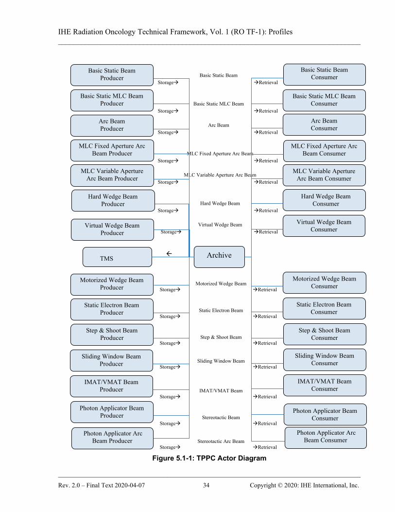
5.1 Actors / Transactions Figure 5.1-1 shows the actors directly involved in the TPPC Profile and the relevant transactions between them. If needed for context, other actors that may be indirectly involved due to their participation in other related profiles are shown in dotted lines. Actors which have a mandatory grouping are shown in conjoined boxes. 745
IHE Radiation Oncology Technical Framework, Vol. 1 (RO TF-1): Profiles ______________________________________________________________________________
______________________________________________________________________________ Rev. 2.0 – Final Text 2020-04-07 34 Copyright © 2020: IHE International, Inc.
Figure 5.1-1: TPPC Actor Diagram
Basic Static Beam Producer
Archive
Basic Static Beam Storage Retrieval
Basic Static MLC Beam Storage Retrieval
Arc Beam
Storage Retrieval
MLC Fixed Aperture Arc Beam Storage Retrieval
MLC Variable Aperture Arc Beam
Storage Retrieval
Hard Wedge Beam Storage Retrieval
Virtual Wedge Beam
Storage Retrieval
IMAT/VMAT Beam Producer
Basic Static MLC Beam
Producer
Arc Beam Consumer
Sliding Window Beam
Producer
Arc Beam Producer
Motorized Wedge Beam
Producer
Photon Applicator Arc Beam Producer
Static Electron Beam
Producer
Hard Wedge Beam Consumer
MLC Variable Aperture
Arc Beam Consumer
Step & Shoot Beam
Producer
Photon Applicator Beam Producer
Virtual Wedge Beam
Producer
Hard Wedge Beam
Producer
Motorized Wedge Beam
Consumer
Basic Static Beam Consumer
Basic Static MLC Beam
Consumer
Step & Shoot Beam
Consumer
Static Electron Beam Consumer
Virtual Wedge Beam Consumer
MLC Fixed Aperture Arc Beam Consumer
IMAT/VMAT Beam Consumer
Sliding Window Beam
Consumer
Photon Applicator Arc Beam Consumer
Photon Applicator Beam Consumer
MLC Fixed Aperture Arc
Beam Producer
MLC Variable Aperture
Arc Beam Producer
Motorized Wedge Beam Storage Retrieval
Static Electron Beam Storage Retrieval
Step & Shoot Beam Storage Retrieval
Sliding Window Beam Storage Retrieval
IMAT/VMAT Beam Storage Retrieval
Stereotactic Beam Storage Retrieval
Stereotactic Arc Beam Storage Retrieval
TMS

IHE Radiation Oncology Technical Framework, Vol. 1 (RO TF-1): Profiles ______________________________________________________________________________
______________________________________________________________________________ Rev. 2.0 – Final Text 2020-04-07 35 Copyright © 2020: IHE International, Inc.
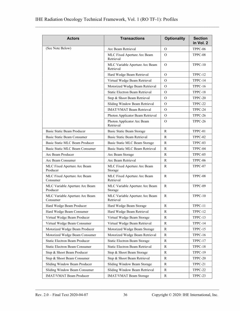
Table 5.1-1 lists the transactions for each actor directly involved in the TPPC Profile. In order to claim support of this Profile, an implementation of an actor must perform the required 750 transactions (labeled “R”) and may support the optional transactions (labeled “O”). Actor groupings are further described in Section 5.3.
Table 5.1-1: TPPC Profile - Actors and Transactions Actors Transactions Optionality Section
in Vol. 2 Archive Basic Static Beam Storage R TPPC-01
Basic Static Beam Retrieval R TPPC-02 Basic Static MLC Beam Storage R TPPC-03 Basic Static MLC Beam Retrieval R TPPC-04 Arc Beam Storage R TPPC-05 Arc Beam Retrieval R TPPC-06 MLC Fixed Aperture Arc Beam Storage
R TPPC-07
MLC Fixed Aperture Arc Beam Retrieval
R TPPC-08
MLC Variable Aperture Arc Beam Storage
R TPPC-09
MLC Variable Aperture Arc Beam Retrieval
R TPPC-10
Hard Wedge Beam Storage R TPPC-11 Hard Wedge Beam Retrieval R TPPC-12 Virtual Wedge Beam Storage R TPPC-13 Virtual Wedge Beam Retrieval R TPPC-14 Motorized Wedge Beam Storage R TPPC-15 Motorized Wedge Beam Retrieval R TPPC-16 Static Electron Beam Storage R TPPC-17 Static Electron Beam Retrieval R TPPC-18 Step & Shoot Beam Storage R TPPC-19 Step & Shoot Beam Retrieval R TPPC-20 Sliding Window Beam Storage R TPPC-21 Sliding Window Beam Retrieval R TPPC-22 IMAT/VMAT Beam Storage R TPPC-23 IMAT/VMAT Beam Retrieval R TPPC-24 Photon Applicator Beam Storage R TPPC-25 Photon Applicator Beam Retrieval R TPPC-26 Photon Applicator Arc Beam Storage
R TPPC-27
Photon Applicator Arc Beam Retrieval
R TPPC-28
Treatment Management System (TMS)
Basic Static Beam Retrieval O TPPC-02 Basic Static MLC Beam Retrieval O TPPC-04
IHE Radiation Oncology Technical Framework, Vol. 1 (RO TF-1): Profiles ______________________________________________________________________________
______________________________________________________________________________ Rev. 2.0 – Final Text 2020-04-07 36 Copyright © 2020: IHE International, Inc.
Actors Transactions Optionality Section in Vol. 2
(See Note Below) Arc Beam Retrieval O TPPC-06 MLC Fixed Aperture Arc Beam Retrieval
O TPPC-08
MLC Variable Aperture Arc Beam Retrieval
O TPPC-10
Hard Wedge Beam Retrieval O TPPC-12 Virtual Wedge Beam Retrieval O TPPC-14 Motorized Wedge Beam Retrieval O TPPC-16 Static Electron Beam Retrieval O TPPC-18 Step & Shoot Beam Retrieval O TPPC-20 Sliding Window Beam Retrieval O TPPC-22 IMAT/VMAT Beam Retrieval O TPPC-24 Photon Applicator Beam Retrieval O TPPC-26 Photon Applicator Arc Beam Retrieval
O TPPC-26
Basic Static Beam Producer Basic Static Beam Storage R TPPC-01 Basic Static Beam Consumer Basic Static Beam Retrieval R TPPC-02 Basic Static MLC Beam Producer Basic Static MLC Beam Storage R TPPC-03 Basic Static MLC Beam Consumer Basic Static MLC Beam Retrieval R TPPC-04 Arc Beam Producer Arc Beam Storage R TPPC-05 Arc Beam Consumer Arc Beam Retrieval R TPPC-06 MLC Fixed Aperture Arc Beam Producer
MLC Fixed Aperture Arc Beam Storage
R TPPC-07
MLC Fixed Aperture Arc Beam Consumer
MLC Fixed Aperture Arc Beam Retrieval
R TPPC-08
MLC Variable Aperture Arc Beam Producer
MLC Variable Aperture Arc Beam Storage
R TPPC-09
MLC Variable Aperture Arc Beam Consumer
MLC Variable Aperture Arc Beam Retrieval
R TPPC-10
Hard Wedge Beam Producer Hard Wedge Beam Storage R TPPC-11 Hard Wedge Beam Consumer Hard Wedge Beam Retrieval R TPPC-12 Virtual Wedge Beam Producer Virtual Wedge Beam Storage R TPPC-13 Virtual Wedge Beam Consumer Virtual Wedge Beam Retrieval R TPPC-14 Motorized Wedge Beam Producer Motorized Wedge Beam Storage R TPPC-15 Motorized Wedge Beam Consumer Motorized Wedge Beam Retrieval R TPPC-16 Static Electron Beam Producer Static Electron Beam Storage R TPPC-17 Static Electron Beam Consumer Static Electron Beam Retrieval R TPPC-18 Step & Shoot Beam Producer Step & Shoot Beam Storage R TPPC-19 Step & Shoot Beam Consumer Step & Shoot Beam Retrieval R TPPC-20 Sliding Window Beam Producer Sliding Window Beam Storage R TPPC-21 Sliding Window Beam Consumer Sliding Window Beam Retrieval R TPPC-22 IMAT/VMAT Beam Producer IMAT/VMAT Beam Storage R TPPC-23

IHE Radiation Oncology Technical Framework, Vol. 1 (RO TF-1): Profiles ______________________________________________________________________________
______________________________________________________________________________ Rev. 2.0 – Final Text 2020-04-07 37 Copyright © 2020: IHE International, Inc.
Actors Transactions Optionality Section in Vol. 2
IMAT/VMAT Beam Consumer IMAT/VMAT Beam Retrieval R TPPC-24 Photon Applicator Beam Producer Stereotactic Beam Storage R TPPC-25 Photon Applicator Beam Consumer Stereotactic Beam Retrieval R TPPC-26 Photon Applicator Arc Beam Producer
Stereotactic Arc Beam Storage R TPPC-27
Photon Applicator Arc Beam Consumer
Stereotactic Arc Beam Retrieval R TPPC-28
Note: The TMS Integration Statement will indicate which transactions it is capable of supporting. In general, these will be grouped according to the overall functionality of the TMS Actor. For example, a general TMS would likely 755 support all 14 transactions, while a Radiosurgery TMS may only support the Stereotactic-oriented beams. In addition, for cases where there are insufficient actors for complete testing of the TMS, the TMS can pass the Connectathon by claiming those transactions it successfully completed.
5.1.1 Actor Descriptions and Actor Profile Requirements 760 Normative requirements are typically documented in Volume 2 (Transactions) and Volume 3 (Content Modules). Some Integration Profiles, however, contain requirements which link transactions, data, and/or behavior. Those Profile requirements are documented in this section as normative requirements (“shall”).
5.2 TPPC Transaction Options 765
Options that may be selected for this profile are listed in the Table 5.2-1 along with the transactions to which they apply. In Table 5.1-1, each * Beam Producer has exactly one transaction, * Beam Storage. Similarly, each * Beam Consumer has exactly one transaction, * Beam Retrieval. For each of these, there are additional content options as noted in Table 5.2-1 from the set of {Bolus, Block, Compensator, Hard Wedge}. One or more of these content 770 additions can be added to the base transaction based on the Integration Statement for the application. The Archive Actor must implement all options of all transactions. The TMS Actor must implement all options of all Retrieval transactions. Dependencies between options when applicable are specified in notes. 775
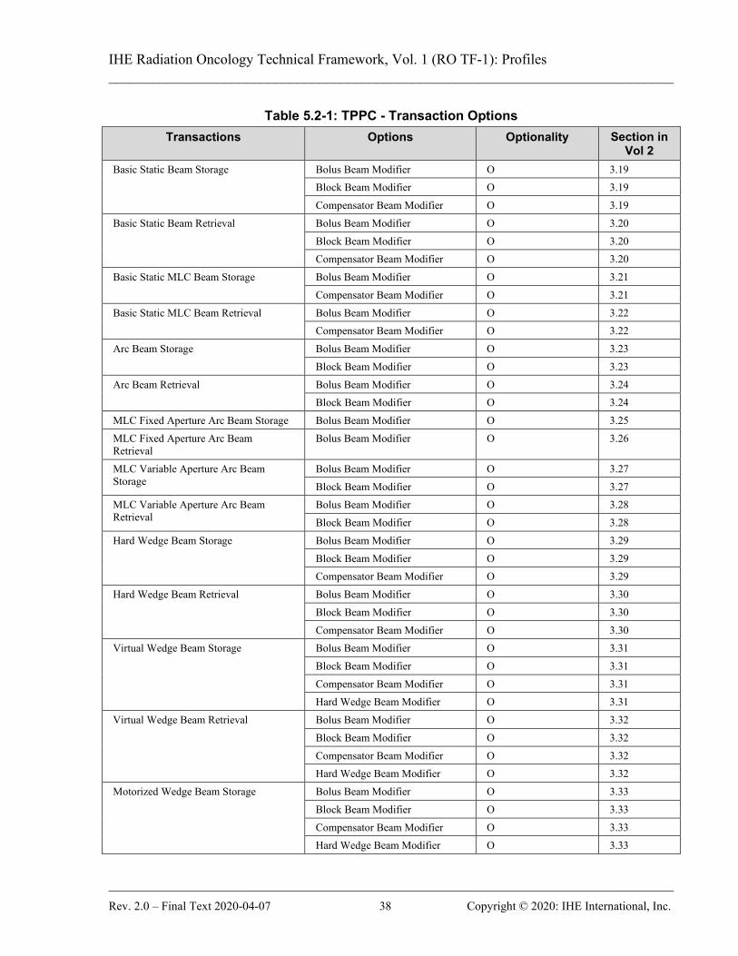
IHE Radiation Oncology Technical Framework, Vol. 1 (RO TF-1): Profiles ______________________________________________________________________________
______________________________________________________________________________ Rev. 2.0 – Final Text 2020-04-07 38 Copyright © 2020: IHE International, Inc.
Table 5.2-1: TPPC - Transaction Options Transactions Options Optionality Section in
Vol 2 Basic Static Beam Storage Bolus Beam Modifier O 3.19
Block Beam Modifier O 3.19 Compensator Beam Modifier O 3.19
Basic Static Beam Retrieval Bolus Beam Modifier O 3.20 Block Beam Modifier O 3.20 Compensator Beam Modifier O 3.20
Basic Static MLC Beam Storage Bolus Beam Modifier O 3.21 Compensator Beam Modifier O 3.21
Basic Static MLC Beam Retrieval Bolus Beam Modifier O 3.22 Compensator Beam Modifier O 3.22
Arc Beam Storage Bolus Beam Modifier O 3.23 Block Beam Modifier O 3.23
Arc Beam Retrieval Bolus Beam Modifier O 3.24 Block Beam Modifier O 3.24
MLC Fixed Aperture Arc Beam Storage Bolus Beam Modifier O 3.25 MLC Fixed Aperture Arc Beam Retrieval
Bolus Beam Modifier O 3.26
MLC Variable Aperture Arc Beam Storage
Bolus Beam Modifier O 3.27 Block Beam Modifier O 3.27
MLC Variable Aperture Arc Beam Retrieval
Bolus Beam Modifier O 3.28 Block Beam Modifier O 3.28
Hard Wedge Beam Storage Bolus Beam Modifier O 3.29 Block Beam Modifier O 3.29 Compensator Beam Modifier O 3.29
Hard Wedge Beam Retrieval Bolus Beam Modifier O 3.30 Block Beam Modifier O 3.30 Compensator Beam Modifier O 3.30
Virtual Wedge Beam Storage Bolus Beam Modifier O 3.31 Block Beam Modifier O 3.31 Compensator Beam Modifier O 3.31 Hard Wedge Beam Modifier O 3.31
Virtual Wedge Beam Retrieval Bolus Beam Modifier O 3.32 Block Beam Modifier O 3.32 Compensator Beam Modifier O 3.32 Hard Wedge Beam Modifier O 3.32
Motorized Wedge Beam Storage Bolus Beam Modifier O 3.33 Block Beam Modifier O 3.33 Compensator Beam Modifier O 3.33 Hard Wedge Beam Modifier O 3.33

IHE Radiation Oncology Technical Framework, Vol. 1 (RO TF-1): Profiles ______________________________________________________________________________
______________________________________________________________________________ Rev. 2.0 – Final Text 2020-04-07 39 Copyright © 2020: IHE International, Inc.
Transactions Options Optionality Section in Vol 2
Motorized Wedge Beam Retrieval Bolus Beam Modifier O 3.34 Block Beam Modifier O 3.34 Compensator Beam Modifier O 3.34 Hard Wedge Beam Modifier O 3.34
Static Electron Beam Storage
Bolus Beam Modifier O 3.35 Block Beam Modifier O 3.35 Compensator Beam Modifier O 3.35
Static Electron Beam Retrieval
Bolus Beam Modifier O 3.36 Block Beam Modifier O 3.36 Compensator Beam Modifier O 3.36
Step & Shoot Beam Storage Bolus Beam Modifier O 3.37 Block Beam Modifier O 3.37 Compensator Beam Modifier O 3.37 Hard Wedge Beam Modifier O 3.37
Step & Shoot Beam Retrieval Bolus Beam Modifier O 3.38 Block Beam Modifier O 3.38 Compensator Beam Modifier O 3.38 Hard Wedge Beam Modifier O 3.38
Sliding Window Beam Storage Bolus Beam Modifier O 3.39 Block Beam Modifier O 3.39 Compensator Beam Modifier O 3.39 Hard Wedge Beam Modifier O 3.39
Sliding Window Beam Retrieval Bolus Beam Modifier O 3.40 Block Beam Modifier O 3.40 Compensator Beam Modifier O 3.40 Hard Wedge Beam Modifier O 3.40
IMAT/VMAT Beam Storage Bolus Beam Modifier O 3.41 IMAT/VMAT Beam Retrieval Bolus Beam Modifier O 3.42 Photon Applicator Beam Storage Bolus Beam Modifier O 3.43 Photon Applicator Beam Retrieval Bolus Beam Modifier O 3.44 Photon Applicator Arc Beam Storage Bolus Beam Modifier O 3.45 Photon Applicator Arc Beam Retrieval Bolus Beam Modifier O 3.46
IHE Radiation Oncology Technical Framework, Vol. 1 (RO TF-1): Profiles ______________________________________________________________________________
______________________________________________________________________________ Rev. 2.0 – Final Text 2020-04-07 40 Copyright © 2020: IHE International, Inc.
5.2.1 Producer / Consumer Transaction Groupings Although not within the scope of this profile, it is possible for a clinical application to produce a 780 treatment plan using several beams, each of which is defined by a different Beam Storage transaction as defined in this profile. For Producers, it is clinically acceptable for them to create a treatment plan with beams satisfying any of the Producer transactions with which they claim adherence. For such cases, a Consumer Actor which also claims adherence to Beam Retrieval transactions encompassing the composited treatment plan may be able to receive such a plan 785 containing a mixed transaction set of beams. However, if the Consumer Actor cannot accept a plan with such a mixed set of beams, it must be able to handle the rejection of the plan in a safe manner. Although an application may claim adherence to a set of transactions involving one or more Producer / Consumer pairs, the plan produced may not be deliverable by the equipment defined 790 in a specific SOP instance created by a transaction. It is not required that all transactions defined in this profile are capable of being delivered by all delivery devices. As a result, there may be single transaction plans, or mixed transaction plans, that are not capable of being delivered by a given delivery device, even though it is defined as the delivery device in the treatment plan. The application user must be aware of the limitations of their delivery equipment, and should 795 configure, where possible, their treatment planning systems and treatment management systems so that such incompatible plans cannot be created. Where such configuration is not possible, the application user should be aware of the limitations, and recognize that such plans may fail to be accepted when transferred to the delivery equipment, which is responsible for handling such incompatible plans in a safe manner. 800
5.3 TPPC Actor Required Groupings None.
5.4 TPPC Overview This integration profile involves the exchange of RT Plan information between treatment planning systems and between treatment planning systems and treatment management systems. 805 The emphasis for this profile is on reducing ambiguity involved in re-planning and incorporation of the planning information into the treatment management system in anticipation of transfer to a treatment delivery system.
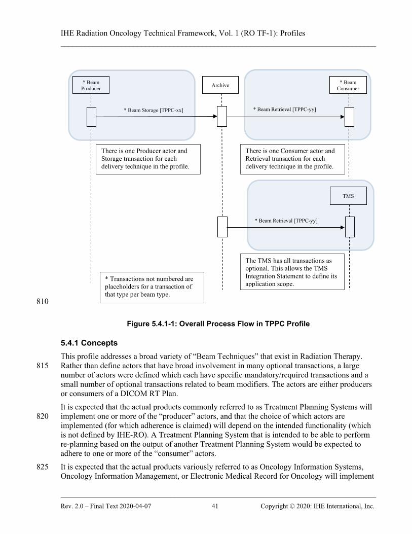
IHE Radiation Oncology Technical Framework, Vol. 1 (RO TF-1): Profiles ______________________________________________________________________________
______________________________________________________________________________ Rev. 2.0 – Final Text 2020-04-07 41 Copyright © 2020: IHE International, Inc.
810
Figure 5.4.1-1: Overall Process Flow in TPPC Profile
5.4.1 Concepts This profile addresses a broad variety of “Beam Techniques” that exist in Radiation Therapy. Rather than define actors that have broad involvement in many optional transactions, a large 815 number of actors were defined which each have specific mandatory/required transactions and a small number of optional transactions related to beam modifiers. The actors are either producers or consumers of a DICOM RT Plan. It is expected that the actual products commonly referred to as Treatment Planning Systems will implement one or more of the “producer” actors, and that the choice of which actors are 820 implemented (for which adherence is claimed) will depend on the intended functionality (which is not defined by IHE-RO). A Treatment Planning System that is intended to be able to perform re-planning based on the output of another Treatment Planning System would be expected to adhere to one or more of the “consumer” actors. It is expected that the actual products variously referred to as Oncology Information Systems, 825 Oncology Information Management, or Electronic Medical Record for Oncology will implement
* Beam Producer Archive * Beam
Consumer
* Beam Storage [TPPC-xx]
* Beam Retrieval [TPPC-yy]
There is one Producer actor and Storage transaction for each delivery technique in the profile.
There is one Consumer actor and Retrieval transaction for each delivery technique in the profile.
TMS
* Beam Retrieval [TPPC-yy]
The TMS has all transactions as optional. This allows the TMS Integration Statement to define its application scope. * Transactions not numbered are
placeholders for a transaction of that type per beam type.
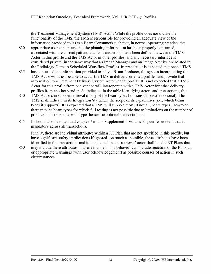
IHE Radiation Oncology Technical Framework, Vol. 1 (RO TF-1): Profiles ______________________________________________________________________________
______________________________________________________________________________ Rev. 2.0 – Final Text 2020-04-07 42 Copyright © 2020: IHE International, Inc.
the Treatment Management System (TMS) Actor. While the profile does not dictate the functionality of the TMS, the TMS is responsible for providing an adequate view of the information provided to it (as a Beam Consumer) such that, in normal operating practice, the appropriate user can ensure that the planning information has been properly consumed, 830 associated with the correct patient, etc. No transactions have been defined between the TMS Actor in this profile and the TMS Actor in other profiles, and any necessary interface is considered private (in the same way that an Image Manager and an Image Archive are related in the Radiology Domain Scheduled Workflow Profile). In practice, it is expected that once a TMS has consumed the information provided to it by a Beam Producer, the system incorporating the 835 TMS Actor will then be able to act as the TMS in delivery-oriented profiles and provide that information to a Treatment Delivery System Actor in that profile. It is not expected that a TMS Actor for this profile from one vendor will interoperate with a TMS Actor for other delivery profiles from another vendor. As indicated in the table identifying actors and transactions, the TMS Actor can support retrieval of any of the beam types (all transactions are optional). The 840 TMS shall indicate in its Integration Statement the scope of its capabilities (i.e., which beam types it supports). It is expected that a TMS will support most, if not all, beam types. However, there may be beam types for which full testing is not possible due to limitations on the number of producers of a specific beam type, hence the optional transaction list. It should also be noted that chapter 7 in this Supplement’s Volume 3 specifies content that is 845 mandatory across all transactions. Finally, there are individual attributes within a RT Plan that are not specified in this profile, but have significant safety implications if ignored. As much as possible, these attributes have been identified in the transactions and it is indicated that a ‘retrieval’ actor shall handle RT Plans that may include these attributes in a safe manner. This behavior can include rejection of the RT Plan 850 or appropriate warmings (with user acknowledgement) as possible courses of action in such circumstances.
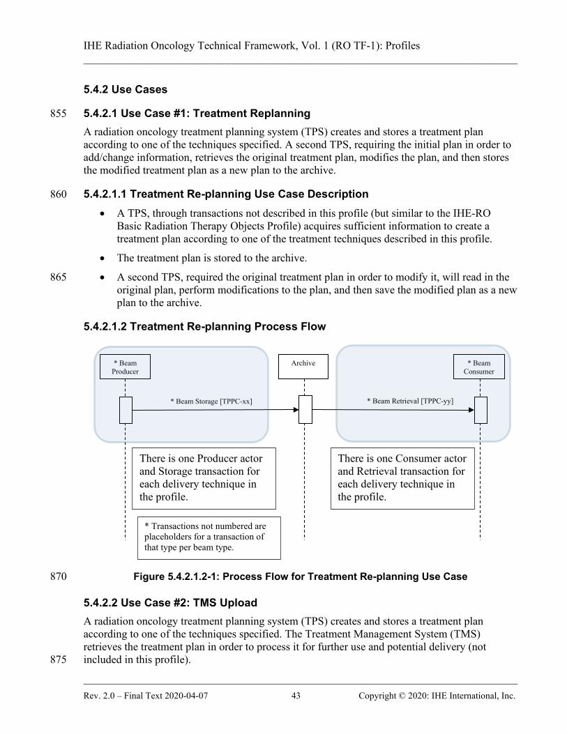
IHE Radiation Oncology Technical Framework, Vol. 1 (RO TF-1): Profiles ______________________________________________________________________________
______________________________________________________________________________ Rev. 2.0 – Final Text 2020-04-07 43 Copyright © 2020: IHE International, Inc.
5.4.2 Use Cases
5.4.2.1 Use Case #1: Treatment Replanning 855 A radiation oncology treatment planning system (TPS) creates and stores a treatment plan according to one of the techniques specified. A second TPS, requiring the initial plan in order to add/change information, retrieves the original treatment plan, modifies the plan, and then stores the modified treatment plan as a new plan to the archive.
5.4.2.1.1 Treatment Re-planning Use Case Description 860
• A TPS, through transactions not described in this profile (but similar to the IHE-RO Basic Radiation Therapy Objects Profile) acquires sufficient information to create a treatment plan according to one of the treatment techniques described in this profile.
• The treatment plan is stored to the archive.
• A second TPS, required the original treatment plan in order to modify it, will read in the 865 original plan, perform modifications to the plan, and then save the modified plan as a new plan to the archive.
5.4.2.1.2 Treatment Re-planning Process Flow
Figure 5.4.2.1.2-1: Process Flow for Treatment Re-planning Use Case 870
5.4.2.2 Use Case #2: TMS Upload A radiation oncology treatment planning system (TPS) creates and stores a treatment plan according to one of the techniques specified. The Treatment Management System (TMS) retrieves the treatment plan in order to process it for further use and potential delivery (not included in this profile). 875
* Beam Producer
Archive * Beam Consumer
* Beam Storage [TPPC-xx]
There is one Producer actor and Storage transaction for each delivery technique in the profile.
There is one Consumer actor and Retrieval transaction for each delivery technique in the profile.
* Beam Retrieval [TPPC-yy]
* Transactions not numbered are placeholders for a transaction of that type per beam type.
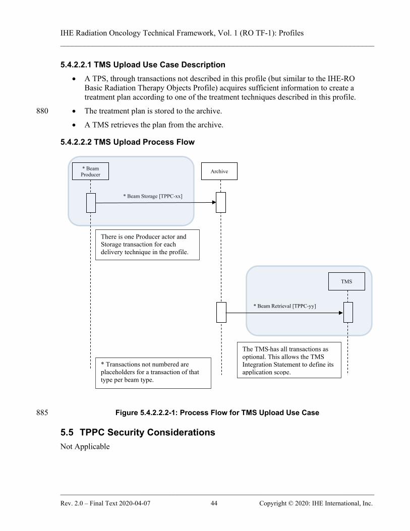
IHE Radiation Oncology Technical Framework, Vol. 1 (RO TF-1): Profiles ______________________________________________________________________________
______________________________________________________________________________ Rev. 2.0 – Final Text 2020-04-07 44 Copyright © 2020: IHE International, Inc.
5.4.2.2.1 TMS Upload Use Case Description • A TPS, through transactions not described in this profile (but similar to the IHE-RO
Basic Radiation Therapy Objects Profile) acquires sufficient information to create a treatment plan according to one of the treatment techniques described in this profile.
• The treatment plan is stored to the archive. 880
• A TMS retrieves the plan from the archive.
5.4.2.2.2 TMS Upload Process Flow
Figure 5.4.2.2.2-1: Process Flow for TMS Upload Use Case 885
5.5 TPPC Security Considerations Not Applicable
* Beam Producer Archive
* Beam Storage [TPPC-xx]
There is one Producer actor and Storage transaction for each delivery technique in the profile.
TMS
* Beam Retrieval [TPPC-yy]
The TMS has all transactions as optional. This allows the TMS Integration Statement to define its application scope.
* Transactions not numbered are placeholders for a transaction of that type per beam type.

IHE Radiation Oncology Technical Framework, Vol. 1 (RO TF-1): Profiles ______________________________________________________________________________
______________________________________________________________________________ Rev. 2.0 – Final Text 2020-04-07 45 Copyright © 2020: IHE International, Inc.
5.6 TPPC Cross Profile Considerations Not applicable 890
IHE Radiation Oncology Technical Framework, Vol. 1 (RO TF-1): Profiles ______________________________________________________________________________
______________________________________________________________________________ Rev. 2.0 – Final Text 2020-04-07 46 Copyright © 2020: IHE International, Inc.
Appendices 895
Appendix A – Actor Descriptions Actors are information systems or components of information systems that produce, manage, or act on information associated with operational activities in the enterprise. The following are definitions of actors used in the IHE Radiation Oncology Integration Profiles: Acquisition Modality – A system that acquires and creates medical images while a patient is 900 present, e.g., a Computed Tomography scanner or Nuclear Medicine camera. A modality may also create other evidence objects such as Grayscale Softcopy Presentation States for the consistent viewing of images or Evidence Documents containing measurements. Archive – A system that provides long term storage of evidence objects such as images, presentation states, Key Image Notes and Evidence Documents. 905 Contourer – A system that consumes one or more CT image series and creates an RT Structure Set. If the Contourer consumes multiple CT image series or has an internal requirement for resampling, it also will generate a single CT image series to which the RT Structure Set maps. A Contourer shall be able to consume CT image series with non-uniform spacing. Dosimetric Planner – A system that consumes a single CT image series, an RT Structure Set, 910 and a Geometric Plan and creates a Dosimetric Plan and an RT Dose. Archive (including RT) – A system that stores the RT SOP Classes in addition to the CT images and is capable of transmitting them. Dose Displayer – A system that consumes a Dosimetric Plan, a single CT image series, an RT Structure Set, and an RT Dose and displays the dose. 915 Registrator – A system that consumes multi-modality images and generates 1 or more Spatial Registration objects. Registered Contourer – A system that consumes multi-modality images, RT Structure Set objects, and Spatial Registration objects and allows the user to contour images in a Registered Display. 920 Registered Display – A system that consumes multi-modality images, RT Structure Set objects, and Spatial Registration objects and allows the user to display the registered information. Registered Dose Display – A system that consumes multi-modality images, RT Structure Set objects, RT Dose objects and Spatial Registration objects and allows the user to display the registered information. 925 Basic Static Beam Producer – A Treatment Planning System (TPS) capable of producing a radiation therapy treatment plan with static, non-MLC, treatment beams. Basic Static Beam Consumer – A Treatment Planning System (TPS) capable of consuming a radiation therapy treatment plan with static, non-MLC, treatment beams.
IHE Radiation Oncology Technical Framework, Vol. 1 (RO TF-1): Profiles ______________________________________________________________________________
______________________________________________________________________________ Rev. 2.0 – Final Text 2020-04-07 47 Copyright © 2020: IHE International, Inc.
Basic Static MLC Beam Producer – A Treatment Planning System (TPS) capable of producing 930 a radiation therapy treatment plan with static, MLC, treatment beams. Basic Static MLC Beam Consumer – A Treatment Planning System (TPS) capable of consuming a radiation therapy treatment plan with static, MLC, treatment beams. Arc Beam Producer – A Treatment Planning System (TPS) capable of producing a radiation therapy treatment plan with non-MLC Fixed Aperture Arc treatment beams. 935 Arc Beam Consumer – A Treatment Planning System (TPS) capable of consuming a radiation therapy treatment plan with non-MLC Fixed Aperture Arc treatment beams. MLC Fixed Aperture Arc Beam Producer – A Treatment Planning System (TPS) capable of producing a radiation therapy treatment plan with MLC Fixed Aperture Arc treatment beams. MLC Fixed Aperture Arc Beam Consumer – A Treatment Planning System (TPS) capable of 940 consuming a radiation therapy treatment plan with MLC Fixed Aperture Arc treatment beams. MLC Variable Aperture Arc Beam Producer – A Treatment Planning System (TPS) capable of producing a radiation therapy treatment plan with MLC Variable Aperture Arc treatment beams. MLC Variable Aperture Arc Beam Consumer – A Treatment Planning System (TPS) capable 945 of consuming a radiation therapy treatment plan with MLC Variable Aperture Arc treatment beams. Hard Wedge Beam Producer – A Treatment Planning System (TPS) capable of producing a radiation therapy treatment plan with static treatment beams using physical wedges. Hard Wedge Beam Consumer – A Treatment Planning System (TPS) capable of consuming a 950 radiation therapy treatment plan with static treatment beams using physical wedges. Virtual Wedge Beam Producer – A Treatment Planning System (TPS) capable of producing a radiation therapy treatment plan with static treatment beams using virtual wedges. Virtual Wedge Beam Consumer – A Treatment Planning System (TPS) capable of consuming a radiation therapy treatment plan with static treatment beams using virtual wedges. 955 Motorized Wedge Beam Producer – A Treatment Planning System (TPS) capable of producing a radiation therapy treatment plan with static treatment beams using motorized wedges. Motorized Wedge Beam Consumer – A Treatment Planning System (TPS) capable of consuming a radiation therapy treatment plan with static treatment beams using motorized wedges. 960 Static Electron Beam Producer – A Treatment Planning System (TPS) capable of producing a radiation therapy treatment plan with static electron treatment beams. Static Electron Beam Consumer – A Treatment Planning System (TPS) capable of consuming a radiation therapy treatment plan with static electron treatment beams. Step & Shoot Beam Producer – A Treatment Planning System (TPS) capable of producing a 965 radiation therapy treatment plan with step & shoot IMRT treatment beams.

IHE Radiation Oncology Technical Framework, Vol. 1 (RO TF-1): Profiles ______________________________________________________________________________
______________________________________________________________________________ Rev. 2.0 – Final Text 2020-04-07 48 Copyright © 2020: IHE International, Inc.
Step & Shoot Beam Consumer – A Treatment Planning System (TPS) capable of consuming a radiation therapy treatment plan with step & shoot IMRT treatment beams. Sliding Window Beam Producer – A Treatment Planning System (TPS) capable of producing a radiation therapy treatment plan with sliding window IMRT treatment beams. 970 Sliding Window Beam Consumer – A Treatment Planning System (TPS) capable of consuming a radiation therapy treatment plan with sliding window IMRT treatment beams. IMAT/VMAT Beam Producer – A Treatment Planning System (TPS) capable of producing a radiation therapy treatment plan with VMAT/IMAT IMRT treatment beams. IMAT/VMAT Beam Consumer – A Treatment Planning System (TPS) capable of consuming a 975 radiation therapy treatment plan with VMAT/IMAT IMRT treatment beams. Photon Applicator Beam Producer – A Treatment Planning System (TPS) capable of producing a radiation therapy treatment plan with static, stereotactic treatment beams. Photon Applicator Beam Consumer – A Treatment Planning System (TPS) capable of consuming a radiation therapy treatment plan with static, stereotactic treatment beams. 980 Photon Applicator Arc Beam Producer – A Treatment Planning System (TPS) capable of producing a radiation therapy treatment plan with stereotactic arc treatment beams. Photon Applicator Arc Beam Consumer – A Treatment Planning System (TPS) capable of consuming a radiation therapy treatment plan with stereotactic arc treatment beams. Treatment Management System (TMS) – An application providing radiation oncology 985 management services and capable of consuming treatment plans with any of the above treatment techniques. The following table shows which actors are used in which Integration Profiles.
Table A-1: Integration Profile Actors Integration Profile Actor BRTO-II MMRO-III TPPC
Acquisition Modality X Archive X Contourer X Dosimetric Planner X Dose Displayer X Registrator X Registered Contourer X Registered Display X Registered Dose Display X Basic Static Beam Producer X Basic Static Beam Consumer
X Basic Static MLC Beam Producer X Basic Static MLC Beam Consumer X Arc Beam Producer X

IHE Radiation Oncology Technical Framework, Vol. 1 (RO TF-1): Profiles ______________________________________________________________________________
______________________________________________________________________________ Rev. 2.0 – Final Text 2020-04-07 49 Copyright © 2020: IHE International, Inc.
Integration Profile Actor BRTO-II MMRO-III TPPC Arc Beam Consumer X MLC Fixed Aperture Arc Beam Producer X MLC Fixed Aperture Arc Beam Consumer X MLC Variable Aperture Arc Beam Producer X MLC Variable Aperture Arc Beam Consumer X Hard Wedge Beam Producer X Hard Wedge Beam Consumer X Virtual Wedge Beam Producer X Virtual Wedge Beam Consumer X Motorized Wedge Beam Producer X Motorized Wedge Beam Consumer X Static Electron Beam Producer X Static Electron Beam Consumer X Step & Shoot Beam Producer X Step & Shoot Beam Consumer X Sliding Window Beam Producer X Sliding Window Beam Consumer X IMAT/VMAT Beam Producer X IMAT/VMAT Beam Consumer X Photon Applicator Beam Producer X Photon Applicator Beam Consumer X Photon Applicator Arc Beam Producer X Photon Applicator Arc Beam Consumer X Treatment Management System (TMS) X
990
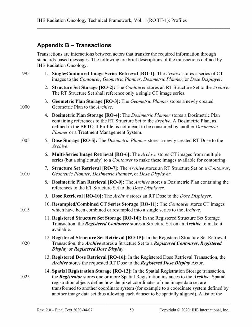
IHE Radiation Oncology Technical Framework, Vol. 1 (RO TF-1): Profiles ______________________________________________________________________________
______________________________________________________________________________ Rev. 2.0 – Final Text 2020-04-07 50 Copyright © 2020: IHE International, Inc.
Appendix B – Transactions Transactions are interactions between actors that transfer the required information through standards-based messages. The following are brief descriptions of the transactions defined by IHE Radiation Oncology.
1. Single/Contoured Image Series Retrieval [RO-1]: The Archive stores a series of CT 995 images to the Contourer, Geometric Planner, Dosimetric Planner, or Dose Displayer.
2. Structure Set Storage [RO-2]: The Contourer stores an RT Structure Set to the Archive. The RT Structure Set shall reference only a single CT image series.
3. Geometric Plan Storage [RO-3]: The Geometric Planner stores a newly created Geometric Plan to the Archive. 1000
4. Dosimetric Plan Storage [RO-4]: The Dosimetric Planner stores a Dosimetric Plan containing references to the RT Structure Set to the Archive. A Dosimetric Plan, as defined in the BRTO-II Profile, is not meant to be consumed by another Dosimetric Planner or a Treatment Management System.
5. Dose Storage [RO-5]: The Dosimetric Planner stores a newly created RT Dose to the 1005 Archive.
6. Multi-Series Image Retrieval [RO-6]: The Archive stores CT images from multiple series (but a single study) to a Contourer to make these images available for contouring.
7. Structure Set Retrieval [RO-7]: The Archive stores an RT Structure Set on a Contourer, Geometric Planner, Dosimetric Planner, or Dose Displayer. 1010
8. Dosimetric Plan Retrieval [RO-9]: The Archive stores a Dosimetric Plan containing the references to the RT Structure Set to the Dose Displayer.
9. Dose Retrieval [RO-10]: The Archive stores an RT Dose to the Dose Displayer. 10. Resampled/Combined CT Series Storage [RO-11]: The Contourer stores CT images
which have been combined or resampled into a single series to the Archive. 1015 11. Registered Structure Set Storage [RO-14]: In the Registered Structure Set Storage
Transaction, the Registered Contourer stores a Structure Set on an Archive to make it available.
12. Registered Structure Set Retrieval [RO-15]: In the Registered Structure Set Retrieval Transaction, the Archive stores a Structure Set to a Registered Contourer, Registered 1020 Display or Registered Dose Display.
13. Registered Dose Retrieval [RO-16]: In the Registered Dose Retrieval Transaction, the Archive stores the requested RT Dose to the Registered Dose Display Actor.
14. Spatial Registration Storage [RO-12]: In the Spatial Registration Storage transaction, the Registrator stores one or more Spatial Registration instances to the Archive. Spatial 1025 registration objects define how the pixel coordinates of one image data set are transformed to another coordinate system (for example to a coordinate system defined by another image data set thus allowing each dataset to be spatially aligned). A list of the

IHE Radiation Oncology Technical Framework, Vol. 1 (RO TF-1): Profiles ______________________________________________________________________________
______________________________________________________________________________ Rev. 2.0 – Final Text 2020-04-07 51 Copyright © 2020: IHE International, Inc.
images used in each Frame of Reference to determine the spatial registration shall be stored in the Spatial Registration instance. 1030
15. Spatial Registration Retrieval: A Registered Display, Registered Dose Display or Registered Contourer receives from an Archive one or more Spatial Registration objects carrying the transformation information to be applied to two image data sets intended for further processing or registered display. Each application receiving a Spatial Registration instance shall compare the image set to be used / displayed to the list of images for each 1035 Frame of Reference and warn the user if additional images are to be displayed for which the spatial registration may not be defined.
16. TPPC-01: Basic Static Beam Storage: In the Basic Static Beam Storage transaction, a Static Beam Producer stores a treatment plan to the Archive. The treatment plan shall contain only static, non-MLC treatment beams. 1040
17. TPPC-02: Basic Static Beam Retrieval: In the Basic Static Beam Retrieval transaction, a Static Beam Consumer or a TMS receives a treatment plan from the Archive. The treatment plan shall contain only static, non-MLC treatment beams.
18. TPPC-03: Basic Static MLC Beam Storage: In the Basic Static MLC Beam Storage transaction, a Static MLC Beam Producer stores a treatment plan to the Archive. The 1045 treatment plan shall contain only static, MLC treatment beams.
19. TPPC-04: Basic Static MLC Beam Retrieval: In the Basic Static MLC Beam Retrieval transaction, a Static MLC Beam Consumer or a TMS receives a treatment plan from the Archive. The treatment plan shall contain only static, MLC treatment beams.
20. TPPC-05: Arc Beam Storage: In the Arc Beam Storage transaction, an Arc Beam 1050 Producer stores a treatment plan to the Archive. The treatment plan shall contain only non-MLC Fixed Aperture Arc treatment beams.
21. TPPC-06: Arc Beam Retrieval: In the Arc Beam Retrieval transaction, an Arc Beam Consumer or a TMS receives a treatment plan from the Archive. The treatment plan shall contain only non-MLC Fixed Aperture Arc treatment beams. 1055
22. TPPC-07: MLC Fixed Aperture Arc Beam Storage: In the MLC Fixed Aperture Arc Beam Storage transaction, an MLC Fixed Aperture Arc Beam Producer stores a treatment plan to the Archive. The treatment plan shall contain only MLC Fixed Aperture Arc treatment beams.
23. TPPC-08: MLC Fixed Aperture Arc Beam Retrieval: In the MLC Fixed Aperture Arc 1060 Beam Retrieval transaction, an MLC Fixed Aperture Arc Beam Consumer or a TMS receives a treatment plan from the Archive. The treatment plan shall contain only MLC Fixed Aperture Arc treatment beams.
24. TPPC-09: MLC Variable Aperture Arc Beam Storage: In the MLC Variable Aperture Arc Beam Storage transaction, a MLC Variable Aperture Arc Beam Producer stores a 1065 treatment plan to the Archive. The treatment plan shall contain only MLC Variable Aperture Arc treatment beams.

IHE Radiation Oncology Technical Framework, Vol. 1 (RO TF-1): Profiles ______________________________________________________________________________
______________________________________________________________________________ Rev. 2.0 – Final Text 2020-04-07 52 Copyright © 2020: IHE International, Inc.
25. TPPC-10: MLC Variable Aperture Arc Beam Retrieval: In the MLC Variable Aperture Arc Beam Retrieval transaction, an MLC Variable Aperture Arc Beam Consumer or a TMS receives a treatment plan from the Archive. The treatment plan shall 1070 contain only MLC Variable Aperture Arc treatment beams.
26. TPPC-11: Hard Wedge Beam Storage: In the Hard Wedge Beam Storage transaction, a Hard Wedge Beam Producer stores a treatment plan to the Archive. The treatment plan shall contain only static treatment beams using physical wedges.
27. TPPC-12: Hard Wedge Beam Retrieval: In the Hard Wedge Beam Retrieval 1075 transaction, a Hard Wedge Beam Consumer or a TMS receives a treatment plan from the Archive. The treatment plan shall contain only static treatment beams using physical wedges.
28. TPPC-13: Virtual Wedge Beam Storage: In the Virtual Wedge Beam Storage transaction, a Virtual Wedge Beam Producer stores a treatment plan to the Archive. The 1080 treatment plan shall contain only static treatment beams using virtual wedges.
29. TPPC-14: Virtual Wedge Beam Retrieval: In the Virtual Wedge Beam Retrieval transaction, a Virtual Wedge Beam Consumer or a TMS receives a treatment plan from the Archive. The treatment plan shall contain only static treatment beams using virtual wedges. 1085
30. TPPC-15: Motorized Wedge Beam Storage: In the Motorized Wedge Beam Storage transaction, a Motorized Wedge Beam Producer stores a treatment plan to the Archive. The treatment plan shall contain only static treatment beams using motorized wedges.
31. TPPC-16: Motorized Wedge Beam Retrieval: In the Motorized Wedge Beam Retrieval transaction, a Motorized Wedge Beam Consumer or a TMS receives a treatment plan 1090 from the Archive. The treatment plan shall contain only static treatment beams using motorized wedges.
32. TPPC-17: Static Electron Beam Storage: In the Static Electron Beam Storage transaction, a Static Electron Beam Producer stores a treatment plan to the Archive. The treatment plan shall contain only static electron treatment beams. 1095
33. TPPC-18: Static Electron Beam Retrieval: In the Static Electron Beam Retrieval transaction, a Static Electron Beam Consumer or a TMS receives a treatment plan from the Archive. The treatment plan shall contain only static electron treatment beams.
34. TPPC-19: Step & Shoot Beam Storage: In the Step & Shoot Beam Storage transaction, a Step & Shoot Beam Producer stores a treatment plan to the Archive. The treatment 1100 plan shall contain only step & shoot IMRT treatment beams.
35. TPPC-20: Step & Shoot Beam Retrieval: In the Step & Shoot Beam Retrieval transaction, a Step & Shoot Beam Consumer or a TMS receives a treatment plan from the Archive. The treatment plan shall contain only step & shoot IMRT treatment beams.
36. TPPC-21: Sliding Window Beam Storage: In the Sliding Window Beam Storage 1105 transaction, a Sliding Window Beam Producer stores a treatment plan to the Archive. The treatment plan shall contain only sliding window IMRT treatment beams.
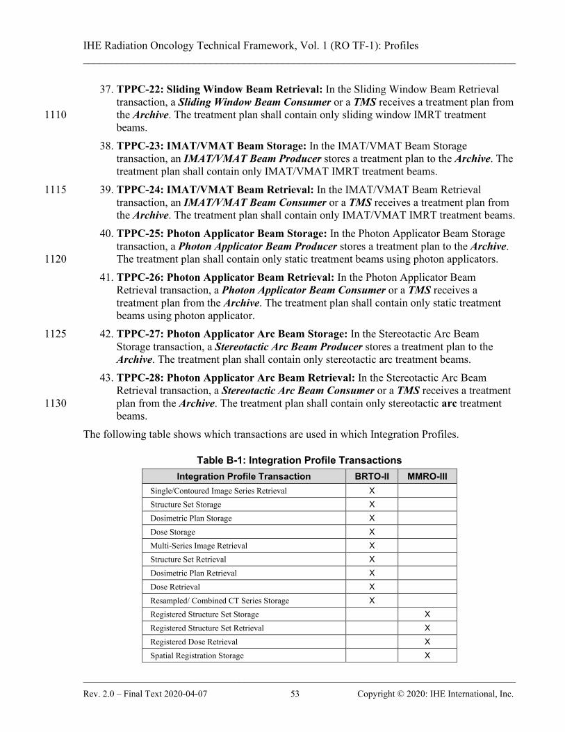
IHE Radiation Oncology Technical Framework, Vol. 1 (RO TF-1): Profiles ______________________________________________________________________________
______________________________________________________________________________ Rev. 2.0 – Final Text 2020-04-07 53 Copyright © 2020: IHE International, Inc.
37. TPPC-22: Sliding Window Beam Retrieval: In the Sliding Window Beam Retrieval transaction, a Sliding Window Beam Consumer or a TMS receives a treatment plan from the Archive. The treatment plan shall contain only sliding window IMRT treatment 1110 beams.
38. TPPC-23: IMAT/VMAT Beam Storage: In the IMAT/VMAT Beam Storage transaction, an IMAT/VMAT Beam Producer stores a treatment plan to the Archive. The treatment plan shall contain only IMAT/VMAT IMRT treatment beams.
39. TPPC-24: IMAT/VMAT Beam Retrieval: In the IMAT/VMAT Beam Retrieval 1115 transaction, an IMAT/VMAT Beam Consumer or a TMS receives a treatment plan from the Archive. The treatment plan shall contain only IMAT/VMAT IMRT treatment beams.
40. TPPC-25: Photon Applicator Beam Storage: In the Photon Applicator Beam Storage transaction, a Photon Applicator Beam Producer stores a treatment plan to the Archive. The treatment plan shall contain only static treatment beams using photon applicators. 1120
41. TPPC-26: Photon Applicator Beam Retrieval: In the Photon Applicator Beam Retrieval transaction, a Photon Applicator Beam Consumer or a TMS receives a treatment plan from the Archive. The treatment plan shall contain only static treatment beams using photon applicator.
42. TPPC-27: Photon Applicator Arc Beam Storage: In the Stereotactic Arc Beam 1125 Storage transaction, a Stereotactic Arc Beam Producer stores a treatment plan to the Archive. The treatment plan shall contain only stereotactic arc treatment beams.
43. TPPC-28: Photon Applicator Arc Beam Retrieval: In the Stereotactic Arc Beam Retrieval transaction, a Stereotactic Arc Beam Consumer or a TMS receives a treatment plan from the Archive. The treatment plan shall contain only stereotactic arc treatment 1130 beams.
The following table shows which transactions are used in which Integration Profiles.
Table B-1: Integration Profile Transactions Integration Profile Transaction BRTO-II MMRO-III
Single/Contoured Image Series Retrieval X Structure Set Storage X Dosimetric Plan Storage X Dose Storage X Multi-Series Image Retrieval X Structure Set Retrieval X Dosimetric Plan Retrieval X Dose Retrieval X Resampled/ Combined CT Series Storage X Registered Structure Set Storage X Registered Structure Set Retrieval X Registered Dose Retrieval X Spatial Registration Storage X

IHE Radiation Oncology Technical Framework, Vol. 1 (RO TF-1): Profiles ______________________________________________________________________________
______________________________________________________________________________ Rev. 2.0 – Final Text 2020-04-07 54 Copyright © 2020: IHE International, Inc.
Integration Profile Transaction BRTO-II MMRO-III Spatial Registration Retrieval X
IHE Radiation Oncology Technical Framework, Vol. 1 (RO TF-1): Profiles ______________________________________________________________________________
______________________________________________________________________________ Rev. 2.0 – Final Text 2020-04-07 55 Copyright © 2020: IHE International, Inc.
IHE Glossary 1135
IHE Glossary terms are maintained via the Standards Knowledge Management Tool (SKMT). SKMT contains IHE Glossary Terms from Final Text and Trial Implementation IHE profiles. Terms from Public Comment profiles are added once the profile is published for Trial Implementation. The current published version of the IHE Glossary (Appendix D to the IHE Technical 1140 Frameworks General Introduction) contains IHE Glossary terms as of the publication date of the document. Always refer to the SKMT for the most up-to-date list of IHE Glossary terms. Further information about SKMT can be found on the IHE Wiki here.
Radiation Oncology Glossary Terms Dosimetric Plan: an RT Plan object containing sufficient information to dosimetrically define a 1145 radiation therapy treatment. The Dosimetric Plan shall contain references to RT Structure Set and RT Dose objects. A Dosimetric Plan shall contain a Fraction Group Sequence (300A,0070) containing a single sequence item. Each beam in the Referenced Beam Sequence (300C,0004) shall have its Beam Meterset (300A,0086) defined. 1150