
IHC JIG VERSUS OTHER GRAVITY SEPARATORS...for the fine grains is substantially less than when...
5
IHC JIG VERSUS OTHER GRAVITY SEPARATORS Gold treatment plant ready lor delivery ""-r-",-_" __ 3 ... 5678910 3" 5678910..." A mineral particle entering the bed has a much longer retention or residence time than is the case in a "thin film" separator. This feature makes the thick-bed separ- ator less sensitive to fluctuations in the feed. A sluice or a jig can treat a wide range and can tolerate fluctuations in 3 of 818910mm S""" H""" """" _. ."""'" $l.UCE80X """'". JKl IHe-JIG CON£S A.Cl'MHG ""'"" _OED , ..... SHAKm "" 1--- CENTRIAJGAl. I I , , I I II II I I I I " I" I I I I I" II Ftg.1. Diagram showing wet gravity separators' operating size rlmge Obviously. the most familiar and wide- spread of the thick-bed separator are the sluice box and the jig. The most important advantage of the thick-bed separator is the "accumulator" effect produced by the sand bed. GRAVITY SEPARATORS THICK-BED VERSUS THIN-BED SEPARATORS Gravity separators can be classi- fied according to the thickness of the solids (sand) bed where the separation takes place. It is astonishing how wide a variety of machinery is being offered for gravity separation. This started with ground slui- ces and later developed into numerous • devices. each claiming to be the answer to a particular separation problem. For wet gravity concentrators. the appli- cability of the most common types per- taining to the particle size range is indi- cated in Fig. 1. For the normal alluvial deposits (also referred to as placers) with the valuable minerals (gold. cassiterite. monazite. rutile. etc.) at a size rangeof 0.05 to 5 mm. the thick and thin bed separators should be considered for the beneficiation pro- cess. -- 4
Transcript of IHC JIG VERSUS OTHER GRAVITY SEPARATORS...for the fine grains is substantially less than when...

IHC JIG VERSUS OTHER GRAVITYSEPARATORS
Gold treatment plant ready lor delivery
""-r-",-_"__~ii~=r---n
3 ... 56789103" 5678910..."
Amineral particle entering the bed has amuch longer retention or residence timethan is the case in a "thin film" separator.This feature makes the thick-bed separator less sensitive to fluctuations in thefeed. A sluice or a jig can treat a widerange and can tolerate fluctuations in
3 of ~ 818910mm
S"""H""""""" _.
."""'"$l.UCE80X
"""'". JKl
IHe-JIG
CON£S
A.Cl'MHG
""'""_OED
,.....SHAKm
""1---
CENTRIAJGAl.
I I , , I I I I II I I I I " I " I I I I I " II
Ftg.1. Diagram showing wet gravity separators' operating size rlmge
Obviously. the most familiar and widespread man~estations of the thick-bedseparator are the sluice box and the jig.The most important advantage of thethick-bed separator is the "accumulator"effect produced by the multi~ayer sandbed.
GRAVITY SEPARATORS
THICK-BED VERSUS THIN-BEDSEPARATORS
Gravity separators can be classified according to the thickness of thesolids (sand) bed where the separationtakes place.
It is astonishing how wide a varietyof machinery is being offered for gravityseparation. This started with ground sluices and later developed into numerous
•devices. each claiming to be the answerto a particular separation problem.For wet gravity concentrators. the applicability of the most common types pertaining to the particle size range is indicated in Fig. 1.For the normal alluvial deposits (alsoreferred to as placers) with the valuableminerals (gold. cassiterite. monazite.rutile. etc.) at asize rangeof 0.05to 5mm.the thick and thin bed separators shouldbe considered for the beneficiation process.
-- 4
Shaking tableIHe-jig sampling result
~- -r ==--- -----Mar1<V11V/i /YVspiral cone.
\( II ~ / )(/ I vy / \/
/ / / / / / \
/ I 1// / /' Riffledsluice
/ / / // V
/ //, 15317.511 1.5 I 1 I I I I I I I I I
10
90
30
80
20
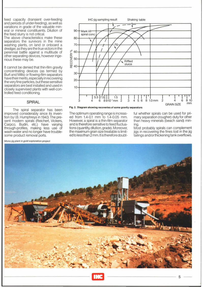
It cannot be denied that thin-film gravityconcentrating devices (as termed byBurt and Mills) or flowing-film separatorshave theirmerits, especially in recoveringthe very fine particles, but these sensitiveseparators are best installed and used inclosely supervised plants with well-<.:ontrolled feed conditioning.
feed capacity (transient over-feedingand periods of under-feeding), as well asvariations in grade of the valuable minerai or mineral constituents. Dilution ofthe feed slurry is not critical.The above characteristics make theseseparators the survivors in the minewashing plants, on land or onboard adredger, as they are the true victors in theperennial battle against a multitude ofother separating devices, however ingenious these may be.
SPIRAL 3 4 6 B9l0-'mm 2 3 4 5 6 B 1.0mm 2 4 6 B 10GRAIN SIZE mm
Fig. 2. Diagram showing recoveries of some gravity separatorsThe spiral separator has been
improVed considerably since its invention by LB. Humphreys in 1943. The present modern spirals (Reichert, Vickers,Carpeo, Budin, etc.) have varyingthrough-profiles, making less use ofwash-water and no longer have troublesome product removal ports.
The optimum operating range is increased from 1.4-0.1 mm to 1.4-0.05 mm.However, a spiral is a thin-film separatorand is therefore sensitive to feed fluctuations (quantity, dilution, grade). Moreover,the maximum grain size treatable is limited to less than 2mm.lt is therefore doubt-
ful whether spirals can be used for primary separation (rougher) duty for otherthan heavy minerals (beach sand) mining.Most probably spirals can complementjigs in recovering the fines lost in the jigtailings and/or thickening tank overflows.
Mono jig plant in gold e1(ploralion proJecl
"..
, .. ~ ~ .. "
.~ ~ -: ' .. ."
•
------10 5 --

Fig. 3. Sluice boxes treating tin ore
PO'n! A PIl.IOdA e ,-~'l(laBD Petloa D·E PIl.1Oll E·F
0 o l• 0 0
0 •• • 0 0.....~O--.- _.-.--_. ._._._. _.-._.-. _.-._._.1-,-,-,-
• •Bllg,nn,ng ot wn,lll 11111 bed 'S BIlCIlUIIl Ihll AI soon as Ine App.ox,malllly" Ow,nlliO C'owd,ngupward SI.okll Olllng 1I111la. Ihe /I'IlIx,mum upwara upward flow Eo IlIell.alnS w,lt Ine orllgra,nl
gra,ns "11 alrllaay 1I0w 'ISO $1.ong. aIlCleaSeI.II,nde'lla bllg,n 10 'ouclI 5"11 !,nk esOtl,ng oul many line pe",cles sll1thng occurs Igl,n TIIIl coarse IIIllIl au"ng
gel loslin InelOp Allllough the'lllS ore has now 'Ilachea Ihe welk sucl,ontlow shll' moment 01 • lower levlll than perioa and Ihll
.n,I,a1 aCCllllllllllOn. aline bllg,nn'ng 01 sana gta,ns comethll h,ndered Ihe upwlrd slro~e, to lie somewhatsllUhng aom,naills Ihll coarse sand a h,gher
h'ghe< Illvel
Flg.4. Pictorial representation of harmonic form jigging cycle
Jusl belOfll po,nl,lt, Perroa e·c Pllflod C·O·F
0 • 0 • 0 0
• • 0
0• 0 0• 0 0
f-o-e--€l .... ._.-.-.- _._._._. .-._._.- _._._._.1-._._._.• • ••
Beg.nn'ng 01 Al Illllllna 01 Ihe Ju!I atler Ihll lhlllllhlcl ollhll When ".egrl,nl DUllngll'le enllleupwara Ilroke upwara Ilfokelhll upwala 1I0w lollowlng perIOd ot Deg,n 10 .0uCIl. Ille suct,on petlOd IIlII
sllual,on ot Ihe has ceased. lI1e h,ndelea IIlW,ngll COllrse Ilna line coerse ore,sIIra,nl ,n rllll,on Ote gra.nl come Ihal the "nl o.e Otl h'_llcOml IbllllO lill10 each Olhllr hes undll. Ihe sand ana IIlIl COlrse lowe. Illan al Ihe SOmewhallowernOI Chanllea IIra,nlowlnlllO sana comll bllg,nn,ng 01 Inll Ino tnel,ne orll
,n'llllicceleral,on logelnllr upward sl.okl. tne consldetltlly lowe.somewh., morll I,nll end coatse on accounl 01closllly. bulthe $Ilnd.l\(lwllvll' IflC~lIng.
hnll lana end Ihll ha_1l movlld upcoafsllorllglll h,ghll'turlner awey Iromeilcholhet
Fig.5. Pictorial representation of IHe sawtooth characteristic jigging cycle
Of course, the jig tailings should then bescreened first at 1.5 or 2 mm; furthermore, cyclone thickening of the feedprior to the spiral is mandatory.The possible additional recovery isshown in Fig. 2. Depending on theamount of these fines, it has to be decided whether it is worthwhile to invest in thiscomplementary spiral circuit. After 2years' spiral plant operation at the Indonesian tin mine ofTambangTimah in Belinyu it was concluded that:'The employment of a spiral in TambangBesar Sumedang II to re-treat tailings stillcontaining tine-grained cassiteriteof 200mesh is effective only as an implement tocheck appropriate or poor jig performance, or whether the performance ofpalongs is suitable or not."However, as aproduction tool to recoverfine cassiterite, it has proved to be inappropriate, observing the pooryield ofcas·siterite and the low tin content, so that toincrease its content to 70% (ready forexport) at the tin shed, there will be substantial losses and much time taken updue to the repeated process".(Pudjohartono Darusman at Intern. Sem.of Mining Technique for Alluvial Tin, lpch1984).
It should also be noted that the additionalrecovery by spirals in regard to IHC jigsfor the fine grains is substantially lessthan when conventional jigs are used.Another warning is also appropriate ingold recovery, as flat, flaky gold can belost more easily when it is swept into thehigher velocity area at the periphery ofthe channel.(Donald J. Cook; Conf. on Alaskan PlacerMining, Fairbanks 1979).
SLUICE BOX
The sluice box, in its various forms,is still being used around the world. Fig. 3depicts the treatment of tin ore by thismethod. Despite the Ubiquitous use ofsluice boxes, thewastefulness of sluicinghas been recognized for quite a longtime.Quite afew mining experts predicted theearly demise of the sluice box. The concensus was expressed by Reaburn in anarticle in the Mining Magazine of March1928: ''This is somewhat premature, butthere is one thing certain and that is, thatthe simple sluice box with the human agitator, though it has served the mine well inthe past, is now proving too wasteful foruse in working poor ground:'Losses in a sluice box vary according tothe nature of the ore treated and theexpertise and opinion of the operator.Donald J. Cook cites loss figures for goldsluices of 10-20% and 15-40%. Thai officials estimate tin losses in asluice box at
--6

5O--+.__.---_---r-_--,__,---L-,__.--_-,
Fig. 6. Diagram showing IHe jig recovery for different capacities
[m3/h)
Solidsfeed
Mean
350 [cu yd/hl
I250
300
& \ Conzinc
'\. &
'\\
I200
250
~... .'-.,..
"--"""Selangordredging
200
I150
Average: 225 cu.yd.lhr. (170 m3/h)at 95% recovery
150
(
100
~'--"':-~••
100
I50
50
Legend:
• Selangor dredging no. 2 dredge results
& Conzinc Sri Timah results
o1o
55
75
60
70
95
90
65
80
85
100 % Recovery
CONVENTIONAL JIGS AND THEIHCJIG
A jig is a gravity concentrator inwhich separation takes place in the thicksand bed, dilated to induced water pulsations. There are numerous types andmodels of jig, and a multitude of theoriesto explain the jigging process.The limitation of jigging studies as aptlydescribed by Kelly and Spottiswood:"Jigging is probably the most complexgravity separation, because of its continuously varying hydro-dynamics. Themineral bed is repeatedly moved up bythe water, expands, and then resettles,the resettlement occurring with the waterflowing down at a lower rate (because ofthe addition of hutch water) than thatwhich occurred on the upstroke.It follows that the wave form itselfmustbea significant parameter; the manner inwhich the bed expands is important, too,because it has a marked effect on theparticle dynamics. A number of experimental studies havebeen reported in theliterature, but too often they fail to contribute to the understanding of jigging. Thisconflicting information appears to arisebecause many studies were carried outon a narrow set of ideal conditions thatresulted in behaviour quite unlike thatassociated with practical jigs".Simply put: Jigging works with an intermittently dilated bed; correct dilation orbed expansion is vital for good separation.
6-25%, but one paper even describes anegative recovery (more tin going outthan coming in) when filling of the sluicebox is prolonged without cleaning.Although it appears that sluicing is not yetextinct, it stands to reason that the additional recovery by jig justifies the replacement of sluice boxes by jigs.
i
"Dale 01 samplong ~2J19U
G,~,1'1 72'1oSn ....... TflHllInFeed 0 262 ~1I1C\l I'd - 0 "9 \gtm
COne: 2861 • - 1631 •
TUong DOl • -0006·
"P\lI'l'Ifoogll-YIOI<l -0.88"RallO 0' COnc:enl'11l0n -I< - 1136El'"1CfImenl RallO - E R - 109 2
TO'" 'llCO"ery 96 21"
ComPlfI$OfI w'llI :b2 C'" "lr. '2' COfWen'JOnal rectafIGUW IIQ
FM<llS6euyOl" ....... 12..,./" ....... C. II;•• _23m·/111..,1
TOlalR-851'\K- IS2ER -13
Salill C.lS5I" Aeea-lef,l' Yf/lY
mm~" "
0300 • 52 '7 99060210 • 72 90 98&10150 .'00 553 91790125 <120 278 95500105 .150 35 91300090 • 170 ,.. 83.330015·200 08 77080063 .240 O' 66070053.300 02 6727
-300 0' '222
)JI'lerlal ....,..., ''''orl (C8SSl18tJtel,-'Cepacny 3061 eu V(l11'1 - 23!1 eu mill - 376 m IIIl
,".
1'0
Fig. 7. Sampling result on radiallHCjlg, type 25, 7.5 m (25 tt) diameter
Hydraulic driving cylinder IHC jig
7 --

Fig. 8. Dramatic difference In treatment plant layout with IHe jigs as compRred to conventional jigs
Mechanical8 Boxes with 4 motors at 4 0 kW - 16.0 kW4 Boxes with 2 molors at 3.0 kW - 6.0 kW6 Boxes with 6 motors at 2.2 kW - 13.2 kW
9.75 kW
7485
IHe radial jigs
300 cu yd/h
230cu m/h
Mechanlcallhydraulil;1 Master unit with 1 motor 9.20 kW1 Oillilling pumpse! 1 molor 0.55 kW
Number 0' celis/jig bed area
I12 Cells trapezoidal typeTolal jigbed area 40 m?
Drive system
Throughput
2 Electric molors
Hutch/back water requirement
100 - 200 m3/h
Feed
35.2 kW18 Boxes wIth 12 motors
Conventional rectangular jigs
60 Cells of 48· x 42"Total Jigbed area 78 m1
900 - 1640 m3fh
A conventional jig, operated with aneccentric drive mechanism, causes aharmonic wave form. The IHC jigemploys a special shaped cam drivesystem which produces afast upstroke slow downstroke (sawtooth) pattern.The effect of the above jigging characteristics on various grains during acompletejigging cycle is visualized in Figs. 4and 5.The proof of the IHC jig's good performance on tin ore has been demonstratedon the Malaysian jumbo dredgers (Fig. 6).One outstanding sampling result isshown in Fig. 7, in which the recovery ratefor each size fraction is shown.
It should be noted that a conventional jighad a much lower recovery figure whenoperating simultaneously on the samedredger and at less than half the specificarea load. The high specific area loadcapability at an acceptable recovery rateresults in the dramatic difference in treatment plant layout with IHC jigs comparedwith a conventional treatment plant configuration, as shown in Fig. 8.
Six-module jig planf during testing
-8