IGEM TECHNICAL SERVICES PAPER...is not well understood but could have significant impact on...
81
IGEM/TSP/16/362 Date: 24/10/2016 IGEM TECHNICAL SERVICES PAPER TITLE: GL report for HSE - Hazards of NCS Gas COMMITTEE/PANEL For: + TCC Information GMC AT MEETING ON: 01/11/2016 GTDC GUC LNGC AUDIT OTHER Gas Quality 9 COMMENTARY:
Transcript of IGEM TECHNICAL SERVICES PAPER...is not well understood but could have significant impact on...

IGEM/TSP/16/362 Date: 24/10/2016
IGEM
TECHNICAL SERVICES PAPER TITLE: GL report for HSE - Hazards of NCS Gas COMMITTEE/PANEL
For: +
TCC Information GMC AT MEETING ON: 01/11/2016 GTDC
GUC
LNGC
AUDIT
OTHER Gas Quality
9
COMMENTARY:

Health and Safety Executive
Hazards arising from the conveyance and use of gas from Non-Conventional Sources (NCS)
Prepared by GL Noble Denton for the Health and Safety Executive 2011
RR882 Research Report

Health and Safety Executive
Hazards arising from the conveyance and use of gas from Non-Conventional Sources (NCS)
Diane Broomhall Glyn Morgan Martin Brown Luisa Shelenko Tim Illson Angie Siddle Yoke Ling Lee Julie Truong Martin Maple
GL Noble Denton Holywell Park Ashby Road Loughborough Leicestershire LE11 3GR
The Health and Safety Executive (HSE) recognises that there is increasing interest in the use of non-conventional source (NCS) gases and that conveyance of the gas from the source to the end user will be through the existing natural gas grid. All gas transported and used has to comply with the Gas Safety (Management) Regulations [GS(M)R] and this raises questions with regard to the suitability of the NCS gas within the network and the possible additional hazards that may result over and above those associated with natural gas.
The HSE commissioned this study to review the available data on NCS gas composition to support assessment of hazards and risks associated with the introduction of NCS gas into pipeline networks.
This report covers the following aspects:
� Collation of data on composition for a range of NCS gas types and sources, including both bulk gas components and contaminants.
� Summary of NCS gas clean-up processes and their performance with regard to removal of contaminants.
� Impact of NCS gas composition on network materials, combustion/utilisation equipment and emissions.
The majority of compounds found in NCS gas are similar to those found in natural gas and thus pose no greater risk to the integrity of the pipeline and downstream equipment, however, siloxanes, high levels of oxygen and highly odiferous compounds need further study.
This report and the work it describes were funded by the Health and Safety Executive (HSE). Its contents, including any opinions and/or conclusions expressed, are those of the authors alone and do not necessarily reflect HSE policy.
HSE Books

© Crown copyright 2011
First published 2011
You may reuse this information (not including logos) free of charge in any format or medium, under the terms of the Open Government Licence. To view the licence visit www.nationalarchives.gov.uk/doc/open-government-licence/, write to the Information Policy Team, The National Archives, Kew, London TW9 4DU, or email [email protected].
Some images and illustrations may not be owned by the Crown so cannot be reproduced without permission of the copyright owner. Enquiries should be sent to [email protected].
ACKNOWLEDGEMENTS
GL would like to gratefully acknowledge the assistance of several companies and individuals that provided measurement data and information related to their work on NCS gas. In particular GL would like to mention the help from National Grid, Centrica, Mark Bugler, John Baldwin, Thorsten Ahrens, Frank Graf, Björn Goffeng, Glenn Mercer, Andrew Dicks, Sandra Esteves, Charles Banks, Jan Stambasky.
ii

CONTENTS
1 Introduction 1
2 Compliance Requirements 3
3 NCS Gas Quality Data 7
3.1 Collation of available data 7
3.2 Gas sampling and analytical techniques 7
3.3 Biogas 8
3.4 Landfill Gas 8
3.5 Coal mine, coal bed, shale gas and underground gasification 8
3.6 SNG from biomass source 8
3.7 NCS summary data 8
4 Gas Clean-up and Removal of Contaminants from NCS Gas 13
4.1 Biogas and landfill gas clean-up processes 14
4.2 SNG from gasification clean-up processes 16
4.3 Coal mine/coal bed gas clean-up processes 18
5 Possible Impacts of using NCS Gas 19
5.1 Assessment of the effects on metallic materials in pipeline 19 infrastructure
5.2 Assessment of the impact of elevated oxygen concentration 25
5.3 Assessment of the effects on non-metallic materials in pipeline 28 infrastructure
5.4 NCS gas and non-metallic materials 31
5.5 Impact on leakage detection 34
5.6 Combustion equipment and processes 35
5.7 Atmospheric emissions 42
5.8 Impacts on health - routes to harm 44
6 45Mitigation of Potential Impacts
iii

7 47NCS Gas Quality Requirements Outside of the UK
7.1 Sweden 47
7.2 The Netherlands 48
7.3 Germany 49
7.4 Switzerland 49
7.5 Austria 50
7.6 California (USA) 50
8 Conclusions 53
9 Recommendations for Further Studies 57
References 59
Glossary 61
Appendix 1 Reference List for Gas Quality Data 63
iv

EXECUTIVE SUMMARY This report provides information for the UK Government Health and Safety Executive (HSE)
including sufficient data to undertake an assessment of hazards and risks associated with the
introduction of non-conventional source (NCS) gas into the existing national gas network.
This will enable HSE to adequately assess any ‘safety case’ submitted under the Gas Safety
(Management) Regulations (GS(M)R) and provide guidance, procedures and processes to
ensure compliance and continued safe operation of the gas network.
This report covers the following :
1. Collation of data on composition for a range of NCS gas
2. Summary of NCS gas clean-up processes 3. Impact of NCS gas composition on network materials
4. Impact of gas composition on combustion equipment
5. Impact of gas composition on emissions
The collation of compositional data showed that there are significant differences between
NCS gas from different sources.
Farm biogas has much higher concentrations of hydrogen sulphide (H2S) and micro-
organisms than waste water biogas and also contains traces of pesticides and pharmaceuticals.
Waste water biogas contains siloxanes and odiferous compounds such as terpenes and
aldehydes whereas farm biogas contains ammonia (NH3). Waste water biogas can also
contain low levels of particulate matter and metals including arsenic.
Landfill gas composition is source dependent. Raw gas from domestic waste is more likely to
contain odiferous compounds such as terpenes and carbonyls. Raw gas from industrial waste
contains the highest levels of arsenic. The total sulphur content of raw landfill gas is
approximately 50% H2S, 50% organic sulphides and thiols so only removing H2S will leave
total sulphur levels above those imposed by GS(M)R. All sulphur-containing compounds will
need to be removed or reduced in concentration to meet the overall gas quality requirements.
Clean-up technologies are available to remove or reduce the minor and trace components of
biogas to result in GS(M)R compliant gas that can be supplied into gas networks. However,
the oxygen and siloxane may need further processing to reduce the concentrations to more
acceptable levels. Clean-up technologies will be able to remove or reduce trace components
of landfill gas but there is concern over organic halides, the performance of siloxane removal
equipment, the presence of a much wider range of contaminants, the presence of
pharmaceuticals and the presence of micro-organisms. Synthetic natural gas (SNG)production and clean-up technologies will be able to produce a gas suitable for injection into
the natural gas grid. However, to date there is only limited information on the performance of
SNG production and there is a need for further studies to demonstrate the overall process and
measure the concentration of trace components. Coal bed and coal mine methane fuels can be
processed and cleaned-up to produce a gas suitable for grid injection. However, the
measurements on trace components are very limited and further studies are required.
The majority of materials degradation risks associated with the introduction of NCS gases
into the metal pipelines of the gas distribution network are dependent on the presence of
water. It is thus crucial to maintain sufficient dehydration of NCS gases before adding to the
natural gas network. The main risk to the gas network is the reliance on the NCS gas supplier
v

to maintain the gas processing units and monitor the gas quality continuously before
introduction into the gas network. In the presence of water, carbon dioxide (CO2) dissolves to
form carbonic acid which then corrodes the iron. NCS gases, especially from SNG
production systems, may contain carbon monoxide and there is potential for stress corrosion
cracking but only if water is present. NCS gases particularly from biogas or landfill gas can
contain ammonia. However, it is unlikely that the concentrations found in NCS gases will
affect the steel unless there is a specific reason for forming concentrated anhydrous ammonia in the system.
The avoidance of issues associated with H2S corrosion in the metal pipelines is dependent on
the NCS supplier maintaining and monitoring the H2S and water removal units effectively, in
the gas clean-up and processing stages. If there is H2S slippage and water is present and the
materials are not sour resistant then cracking due to hydrogen induced cracking (HIC) or
sulphide stress cracking (SSC) may occur. H2S has also been shown to react with copper,
commonly used as installation pipework in domestic premises. The reaction results in copper
sulphide films, which can form ‘black dust’ and may interfere with the correct function of gas
valves and burners.
Low concentrations of mercury in the feedstock gas can be concentrated into pockets of liquid
mercury depending on the operating conditions of the pipeline. Specific mercury removal
equipment should be employed if mercury is known to be present in the raw NCS gas.Provided there is no mechanism for concentrating the mercury, the probability of damage
should be low.
Biogas from a dairy farm, landfill, or waste water treatment plant may all contain bacteria
which could result in microbially-induced corrosion (MIC) in the National Transmission
System (NTS) if there is water present. An ongoing Gas Technology Institute (GTI) project
is aiming to model MIC as a result of bacteria present in biogas. To date, it is an area which
is not well understood but could have significant impact on corrosion in pipelines transporting
biogas and other NCS gas.
The impact of 1, 2 and 3% oxygen in dry or “moist” fuel on gas network materials has been
considered. If the pipeline is dry then internal corrosion of iron and steel should not be a
problem. Corrosion only occurs for a limited period during conditions when water may enter
the pipes from external sources or from leaking joints in low pressure mains. It is generally accepted that oxygen increases the severity of carbon dioxide corrosion. Increasing oxygen
content from 0.2 to 1% doubles the carbonic acid corrosion rate and increasing to 3%
increases the corrosion rate by a factor of four - five. Further research would be required to
determine the effect of higher oxygen partial pressures which would be generated in gas
transmission pipelines.
Another effect of increased oxygen level will be on sulphidation of copper carcassing and
copper alloy components within meters. Oxygen can increase the rate of copper sulphidation
and there may be increased instances of appliance burners and valves/meters being blocked
by flaking copper sulphide.
Overall, it is considered that the risk to the integrity of the pipeline and downstream
equipment is generally no greater for NCS gas than natural gas (with the possible exception of
landfill gas). This is attributed to the relatively low concentrations of many of the compoundspresent in NCS gas that are not otherwise found in natural gas. Nevertheless, the assumption
is made that condensation and accumulation of significant quantities of these substances as
vi

liquids will not occur. Should this happen the risk that materials may suffer harm is
increased.
Odour masking in distribution networks is a well documented phenomenon and there are
many components in NCS gas that will most likely mask completely or attenuate the effect of
added odorant. All odiferous compounds need to be removed or reacted to negate their odour
before network entry.
Some trace components in NCS gas can have an effect on the performance and reliability of
combustion equipment. Any increase in total sulphur levels through the use of NCS gas may
lead to higher rates of sulphuric acid dewpoint corrosion damage in susceptible designs of
stainless steel heat exchangers, and may require the replacement of currently used 316 type
alloys for higher, more corrosion resistant stainless steel grades at increased cost. This may
be an important factor for domestic gas appliances, gas engines, gas turbines and other
utilisation equipment. Raised acidity (lower pH) of flue gas condensate, due to raised
sulphur, chlorine and fluorine levels in NCS gas, would likely lead to increased corrosion in
the water condensate handling sections of stainless steel and particularly aluminium heat
exchangers. Potential problems might include greater levels of corrosion product formation,
resulting in restrictions to flue gas paths and flue gas drainage problems in susceptible
designs. At the present time, there is insufficient knowledge regarding the promotion of
failure modes within appliances and combustion equipment from the presence of silicon-containing compounds to provide a definitive comment on the risk associated with their
presence in the NCS gas. Mercury in NCS gas could cause problems when the gas is burnt.
At high temperatures amalgams can be formed with other metals causing premature failure of
metal components in burners and engines. Heat exchangers in industrial and power plant are
often constructed of aluminium alloys and many domestic boilers contain aluminium
components.
Trace components present in the NCS gas have the potential to impact on the glass making
process in both the melting and finishing stages. Impurities can affect the production of glass
fibre also. Any controlled atmospheres may be compromised by presence of oxygen in the
NCS gas which may impact on product quality. Surface treatment of the glass or annealing
may also be affected by the presence of trace impurities. Siloxanes are not thought to be as
important a contaminant as the glass is formed from silica. Volatile metals may be a nuisance
causing surface imperfections in the finished glass product. Some commercial glass manufacturers have indicated concerns about chlorine in gas.
During the glazing and final product colouring of ceramics, it may be important to have a
very controlled atmosphere and here the trace impurities in NCS gas may give rise to some
concerns.
Emissions from unburned NCS gas would be expected to disperse rapidly and the
concentration of trace component species diluted accordingly and this mechanism is not
thought to be significant in terms of impact on the environment or on human health.
The presence of oxygen in the fuel at levels up to several percent are not expected to alter the
combustion products or process significantly, as the combustion process introduces a high
proportion of oxygen from the air.
The fate of volatile metals during combustion is not fully understood. The total mass emission
will relate to the trace amount present in the fuel but the emitted product may have different
speciation or oxidation state. The concentration of trace metals in NCS gas is expected to be
vii

very low, but it does require further studies to provide more definitive data on the overall
emission.
Siloxane compounds form a set of the most difficult emissions to characterise and potentially
the most severe contaminant to note. Further work on the fate of siloxanes in NCS gas is
required to establish safe operating limits and more details on the combustion products,
including the impact on combustion equipment and the potential for production of airbornesilica particulate emissions.
There is a possibility that pathogenic micro-organisms may survive the NCS clean-up process
and entry into the gas distribution system. Data from farm biogas found that the clean-up
process actually increased the amount of micro-organisms in the gas by providing them with a
suitable habitat for incubation. More work is needed to establish whether pathogens could
migrate and survive in the gas network.
viii

1 INTRODUCTION
European Directive 2003/55/EC provides the framework for admission of biogas or gas from
biomass to the gas network for environmental reasons provided that the gas is compatible
with the existing networks and does not impact adversely on its secure and efficient operation.
[1] It states that: “Member States should ensure that, taking into account the necessary quality
requirements, biogas and gas from biomass or other types of gas, are granted non-
discriminatory access to the gas system, provided such access is permanently compatible with
the relevant technical rules and safety standards. These rules and standards should ensure, that
these gases can technically and safely be delivered into, and transported, through the natural gas system and should also address the chemical characteristics of these gases”.
The Directive 2003/55/EC, also introduces the range of possible non-conventional gases by
stating that the rules: “…. shall also apply to biogas and gas from biomass or other types of
gas in so far such gases can technically and safely be delivered into, and transported through,
the natural gas system".
National Grid, in their document "Transporting Britain's Energy 2009: Development of
Energy Scenarios" [2] have recognised the potential contribution of other methane-based
gaseous fuels, in addition to natural gas, but raise the issue of uncertainty as they state: "….
we have for the first time assumed a small supply contribution from biogas based on a build-
up profile to 1% of all supplies by 2020. There is much uncertainty over the contribution
biogas and other non conventional gas sources (i.e. coal bed methane) could provide, hence
we acknowledge that these flows could be less or considerably more, but their inclusion is recognition of the role they could ultimately play".
Within the UK, gas conveyed in the gas grid network must comply with the requirements of
the Gas Safety (Management) Regulations [GS(M)R] [3] and there are several gas quality and
composition constraints. Part I of Schedule 3 provides details with regard to “CONTENT
AND OTHER CHARACTERISTICS OF GAS”. The characteristic “impurities” has the
specified “value”: “shall be at such levels that they do not interfere with the integrity or
operation of pipes or any gas appliance (within the meaning of regulation 2(1) of the 1994
Regulations) which a consumer could reasonably be expected to operate”.
For a gas supplier to convey gas within the national pipeline network a “Safety Case”
approach with a risk assessment-based evaluation is used to underpin the technical
requirements at the point of entry. Part of the “Safety Case” must relate to the gas quality and
composition.
Within Europe, the collaborative Marcogaz organization (the “Technical Association of the
European Natural Gas Industry”) has reported on recommendations for NCS gas addition to
grids. [4] They conclude that: “Risk assessment prior to injection of any gas, irrespective of
source, is recommended in order to assess requirements for measurement, control and safety
devices. Such risk assessment should therefore consider the additional risks associated with
NCS gases.”; and: “Gas that is distributed on the natural gas grid shall not contain substances
that can cause danger to the health of gas users or other persons that may come into contact
with the gas or its products of combustion. Also, any additional hazard to the natural gas
transport system and of its components shall be avoided. NCS gases with high risk from
biological agents, such as biogas plants feeding gas into the natural gas grid should therefore
1

have a quality assurance system or equivalent proof for handling raw material, gas production
and gas treatment in order to eliminate the risk for contamination.”
The results from this work provides the UK Government Health and Safety Executive (HSE)
with information to undertake an assessment of hazards and risks associated with the
introduction of NCS gas into the existing national gas pipeline network, and enable HSE to
adequately assess any “Safety Case” submitted under GS(M)R and provide guidance,procedures and processes to ensure compliance and the continued safe operation of the gas
network.
2

2 COMPLIANCE REQUIREMENTS
With the aim of ensuring that gas supplied in the UK can be utilised safely and efficiently, a
specification was developed by the HSE, and the then nationalised British Gas utility. This
forms the Gas Safety (Management) Regulations – GS(M)R [3].
This approach uses Wobbe Number (WN), a measure of the heat flux through an appliance,
based on discharge through a burner nozzle, as the primary interchangeability parameter to
provide intercomparison between different gas qualities and form an acceptable gas quality
envelope. Gases supplied within the specified Wobbe Number range, and compliant with other interchangeability parameters [Incomplete Combustion Factor (ICF) and Sooting Index
(SI)] should provide acceptable performance within a certified appliance designed to operate
in the UK. Further details are provided in GS(M)R.
A summary of the GS(M)R limits is shown in the following table (Table 1):
Table 1 Summary of the GS(M)R under normal conditions[3]
Property Range or limit
Hydrogen sulphide (H2S)
Total sulphur (S)
Hydrogen (H2)
Oxygen (O2)
Impurities and water and hydrocarbondewpoints
Wobbe Number
ICF (Incomplete Combustion Factor)
SI (Sooting Index)
Odour
< 5 mg/m3
< 50 mg/m3
< 0.1 mol%
< 0.2 mol%
The gas shall not contain solids or liquids thatmay interfere with the integrity or operation ofthe network or appliances
Between 47.20 and 51.41 MJ/m3 - normal limits.
< 0.48 - normal conditions
< 0.60
Gas below 7 bar (g) will have a stenching agentadded to give a distinctive odour
[UK standard conditions are 15 °C and 1013.25 mbar for both combustion and metering]
In addition to GS(M)R, gas distribution network operators agree a contractual network entry agreement with suppliers of gas into their networks (both transmission and distribution). This
takes the GS(M)R requirements and refines the limits for certain properties to account for
other operational factors, and also extends the approach to additional factors including total
inerts, carbon dioxide, organic halides and calorific value.
As an example the details of National Grid Gas Distribution’s network entry agreement
specification [5] are shown in the following table (Table 2):
3

Table 2 National Grid Gas Entry Specification [5]
Property Range or limit
Hydrogen sulphide
Total sulphur
Hydrogen Content
Oxygen Content
Hydrocarbon dewpoint
Water dewpoint
Wobbe Number
Incomplete combustionfactor (ICF)
Soot index (SI)
Gross calorific value (realgross dry)
Inerts
Contaminants
Organo Halides
Radioactivity
Odour
Pressure
Delivery Temperature
Less than or equal to 5 mg/m3
Less than or equal to 50 mg/m3
Less than or equal to 0.1% (molar)
Less than or equal to 0.001% (molar)
Not more than -2 °C at any pressure up to 85 bar
Not more than -10 °C at 85 bar
Shall be between 47.20 to 51.41 MJ/m3
Not more than 0.48
Not more than 0.60
The Gross Calorific Value (real gross dry) shall be in the range 36.9to 42.3MJ/m3, in compliance with the Wobbe Number, ICF and SI limits described above.
Subject to gas entry location and volumes, a target for the CalorificValue may be set within this range.
Not more than 7.0% (molar)
Subject to Carbon Dioxide (CO2): Not more than 2.0% (molar)
The gas shall not contain solid, liquid or gaseous material that mayinterfere with the integrity or operation of pipes or any gasappliance within the meaning of regulation 2(1) of the Gas Safety(Installation and Use) Regulations 1998 that a consumer could reasonably be expected to operate
Not more than 1.5 mg/m3
Not more than 5 Becquerels/g
Gas shall be odorised with odorant NB (80% tertiarybutyl
mercaptan, 20% dimethyl sulphide) at an odorant injection rate of 6 mg/SCM, which may be varied at the DN Operator’s request by upto plus or minus 2 mg/SCM to meet operational circumstances.
The delivery pressure shall be the pressure required to deliver
natural gas at the Delivery Point into our Entry Facility at any time taking into account the back pressure of our System at the DeliveryPoint as the same shall vary from time to time
The entry pressure shall not exceed the Maximum OperatingPressure at the Delivery Point.
Between 1°C and 38°C
[UK standard conditions are 15 °C and 1013.25 mbar for both combustion and metering.]
With regard to NCS gas, the network entry and GS(M)R requirements must be met before the
gas can be accepted into the network to safeguard the gas users on the network. The key
factor is the Wobbe Number and as such the methane content of the gas has to be high but the
minor and trace components present in the gas are the compounds that require further study to
ensure that their presence does not contravene the requirement that "Gas shall not contain
4

solid, liquid or gaseous material which may interfere with the integrity or operation of pipes
or any gas appliance"
5

6

3 NCS GAS QUALITY DATA
Four classes of raw and processed (cleaned-up) non-conventionally sourced gas were selected
for inclusion in this report:
• Biogas from the anaerobic digestion of sewage sludge, farm waste, energy crops, food
waste and biomethane after clean-up
• Landfill gas – raw and processed
• Coal mine, coal bed and shale gas – raw and processed
• SNG from the gasification of biogas, biomass or coal
3.1 COLLATION OF AVAILABLE DATA
Over 200 documents were obtained, mostly published papers and seminar presentations.
Over 30 organisations were contacted including:
• Gas companies – shippers, distribution companies
• Coal companies
• Trade Associations
• Organising bodies - European and world
• Regulators in Europe
• Research organisations – UK and Europe
• Universities – UK and Europe
• Commercial waste service companies
The response to enquiries has ranged from very helpful, clients allowing us to use confidential
data on an anonymous basis to no response.
3.2 GAS SAMPLING AND ANALYTICAL TECHNIQUES
In addition to compositional data, information regarding gas sampling and measurement
techniques used was also gathered. This was in order to assess the validity of any data sets
that appeared to be outliers from the bulk of typical results. Analytical results obtained bysampling with an accredited method followed by laboratory analysis using an accredited
method was to be given more weight than gas sampled in the field by portable hand-held
devices that may be cross-sensitive to several species. However, examination of all the data
gathered showed that many studies were concerned with only the bulk components and thus
did not provide any information on gas sampling or analytical methods. All data sets
gathered are included in this report.
7

3.3 BIOGAS
The most comprehensive biogas data came from two sources; a GL Noble Denton report for a
client who kindly allowed us to use data obtained from a waste water treatment plant on an
anonymous basis and data from the Gas Technology Institute (GTI) on their work on biogas from dairy farms. Both of these studies monitored for all possible contaminants. The GTI
study also included comprehensive measurements made on biomethane; cleaned up biogas.
There was little data available for fully processed biogas from waste water treatment plant.
Most data is either “high level”; ie covers only the bulk components, or is for partially
processed gas; eg siloxane removal prior to the gas being burnt in a combined heat and power
(CHP) unit.
3.4 LANDFILL GAS
The most comprehensive landfill data came from a two year study carried out by the
Environment Agency to produce a consistent data set for landfill emissions. This provided
excellent data on raw landfill gas but none on processed gas. There is very little data oncleaned up landfill gas even though it is often used as a fuel for in situ gas engines.
3.5 COAL MINE, COAL BED, SHALE GAS AND UNDERGROUND
GASIFICATION
There was limited data for gas from coal mines, coal bed and shale gas with most of it
concerned with only the bulk components. The most comprehensive data for coal mine gas
came from a study carried out by GL Noble Denton (as Advantica Technologies Ltd) on
behalf of National Grid Distribution (as Transco) looking at the risks associated withintroducing coal mine/bed gas into natural gas networks. There is no data on processed coal
mine/bed gas. The lack of data on shale gas was particularly surprising since shale gas
pipelines have been built in Australia and USA and liquefied shale gas will shortly be
imported into the UK.
3.6 SNG FROM BIOMASS SOURCES
The data on SNG produced from biomass sources by either gasification or pyrolysis was more
comprehensive since the concentration of contaminants is an indication of how successful the
gasification/pyrolysis process has been.
3.7 NCS SUMMARY DATA
Appendix 1 contains references to all compositional data gathered for this report. Tables 3 to
6 below summarise all data gathered by giving the concentration ranges for the most
important components/contaminants in raw and cleaned-up gas.
3.7.1 Units of measurement The original data gathered for this report was presented in a variety of units of measurement
and where the data has been condensed for use, the units of measurement have been
harmonised as follows:
• To be consistent with the GS(M)R (Table 1) and the network entry specification
(Table 2), units of measurement for all gaseous components are in mole % except for all
sulphur compounds which are in mg/m3.
8

• With regard to liquid water and hydrocarbon components the regulations are concerned
with condensation and so refer to them in terms of dewpoint. In this report units of
measurements for liquid components are consistent with the appropriate ISO standards.
Thus, ISO10101 (Determination of water in natural gas) [6] defines water content in
mg/m3. ISO23874 (GC requirements for hydrocarbon dewpoint calculation) [7] uses
mole % for all measured gaseous components (up to C12). ISO13686 (Natural gas -
Quality Designation) [8] specifies mg/m3 for liquid hydrocarbons in natural gas. Therefore, all major and minor gaseous components that are typically found in natural
gas including hydrocarbons up to C12 are reported in mole%. Water, all sulphur
compounds and all other compounds not found in natural gas (siloxanes, terpenes,
halides etc) are reported in mg/m3.
• There is one exception. Micro-organisms are usually quantified in terms of colony
forming units (cfu) but sometimes are simply trapped and weighed and there is no
conversion factor.
• Converted concentrations of “Total” species have been converted using the molecular
weight of the most prevalent compound, which is identified in the relevant table.
Table 3 Concentration ranges for contaminants in raw and processed biogas from waste water, farms and energy crops
Contaminant Concentration range
Raw biogas Processed biogas
Methane (CH4)
CO2
H2S
Total sulphur
O2
Moisture
Siloxanes
Organic halides
Micro-organisms
Terpenes
Aldehydes & ketones
Ammonia (NH3)
Arsenic
Total Pesticides & Pharmaceuticals
(as methoxychlor)
40 – 80 mol%
15 – 55 mol%
0 – 45600 mg/m3
Dominated by H2S
0 – 6 mol%
Saturated
0 – 400 mg/m3
0 – 11.5 mg/m3
0 – 280 cfu/m3
0 – 230 mg/m3
0 – 1.22 mg/m3
0.6 – 50 mg/m3
0 – 0.5 µg/m3
0 - 0.001 mg/m3
75 – 99 mol%
0.2 – 25 mol%
0 – 10 mg/m3
Dominated by H2S
0 – 0.9 mol%
32 mg/m3
<1 – 48 mg/m3
0 – 7.4 mg/m3
0 – 1.37x10⁵ cfu/m3
No data
Not detected
9

The summary table covers all types of biogas and the following points should be noted:
• There are differences between biogas from different sources.
• Farm biogas has much higher concentrations of H2S and micro-organisms.
• Farm biogas contains traces of pesticides and pharmaceuticals
• Waste water biogas contains siloxanes and odiferous compounds such as terpenes and
aldehydes • Farm biogas contains NH3
• Waste water biogas contains low levels of particulate matter and metals including arsenic
Table 4 Concentration ranges for contaminants in raw and processed landfill gas from all waste types
Contaminant Concentration range
Raw landfill gas Processed landfill gas
CH4
CO2
H2S
Total sulphur
O2
Moisture
Total siloxanes
(as octamethylcyclotetrasiloxane)
Total organic halides
(as chloroethene)
Micro-organisms
Mercury (Hg)
Arsenic (As)
Carbonyls
Furans
Terpenes
Benzene
22.5 – 70 mol%
9.2 – 60 mol%
0 – 15200 mg/m3
0 – 200 mg/m3
0 – 10 mol%
0 – Saturated
0 – 8000 mg/m3
0 – 842 mg/m3
No data
0.13 – 9.5 µg/m3
0.04 – 430 µg/m3
Up to 42 mg/m3
<10 – 6200 µg/m3
Up to 272 mg/m3
70ppb – 21.2 ppm
88.3 – 99 mol%
1 – 4.7 mol%
0 – 15 mg/m3
No data
0 – 0.1 mol%
No data
<20 mg/m3
0.03 – 3mg/m3
No data
30 ppb
The summary table covers gas from all landfill sources and the following should be noted: • There are differences between landfill gas from different sources
• Raw gas from domestic waste is more likely to contain odiferous compounds such as
terpenes and carbonyls.
10

• Raw gas from industrial waste produces the highest levels of arsenic.
• Raw gas Hg levels are very low but higher than the current UK Export Sales Gas limit of
0.01µg/m3.
• The total sulphur content of raw landfill gas is approximately 50% H2S, 50% organic
sulphides and thiols so only removing H2S will still eave total sulphur levels above those
imposed by GS(M)R.
Table 5 Concentration ranges for contaminants in raw and processed SNG from
gasification of biogas, biomass and coal
Contamination Concentration range
CH4
CO2
Nitrogen (N2)
H2S
Total sulphur
H2
Carbon monoxide (CO)
Moisture
Hydrogen chloride (HCl) /hydrogen fluoride (HF)
Total tar
Raw gas
0 – 81.9 mol%
8.3 – 49.4 mol%
7 – 8 mol%
Not detected
Not detected
4 – 13.2 mol%
0 – 0.5 mol%
All data is on a dry basis
Not detected
17 mg/m3
Processed gas
10 – 96 mol%
0.47 – 8.9 mol%
0.5 – 3 mol%
No data
No data
0.5 – 8 mol%
0.01 – 0.06 mol%
0 – 1268 mg/m3
No data
No data
11

Table 6 Concentration ranges for contaminants in raw coal mine, coal bed and shale gas
Contamination Concentration range
CH4
CO2
N2
H2S
Total sulphur
O2
Moisture
Organic halides
HCl/HF
Micro-organisms
25 – 99.2 mol%
0.6 – 27.5 mol%
0.05 – 59 mol%
5 – 8 mg/m3
Only H2S data
0 – 17 mol%
No data
Not detected
Not detected
No data
12

4 GAS CLEAN-UP AND REMOVAL OF CONTAMINANTS FROM NCS GAS
NCS gas typically requires some processing and clean up to remove or reduce the
concentration of contaminants to produce a gas that may be acceptable for use within natural
gas grids. The type of gas processing required is dependent on the NCS gas source but would
typically involve removal of water, carbon dioxide and hydrogen sulphide. These primary
contaminants require processing as they are limited, either directly or indirectly, by GS(M)R.
In addition, if non-conventional gas quality measurements indicated the significant presence
of other compounds then these too would require removal. The difficulty arises in deciding
which compounds are significant. Some are significant at relatively low concentrations, for
instance mercury, whereas others may be acceptable with higher concentrations. This section
provides outline information on the commercially available gas clean-up technologiestogether with an indication of their performance relating to contaminant removal.
The main types of non-conventional gas clean-up techniques are:
• Water Wash
• Amine Wash
• Cryogenic
• Pressure Swing Adsorption
• Membranes
The main aim of the processing and upgrading process is to increase the methane content of
the gas and reduce other bulk components. Table 7 shows the primary methods used to
remove carbon dioxide and as a consequence increase the proportion of methane.
Table 7 Overview of NCS gas clean-up processes
Technology CH4 concentration
post clean-up (%)
Comments
Water Wash
Amine Wash
Cryogenic
Pressure SwingAdsorption
Membranes
98
99
99+
92
90
Popular technology with a number of suppliers. Claims removal of H2S and Siloxanes, however there is limited post-clean-up data available
Similar to Water Wash but more efficient at CO2 removal. It is more expensive due to amine regeneration processes. Limited post clean-up data available
Claims 100% removal of CO2 and will probably remove
other components. Limited post clean-up data available
Popular technology with a range of suppliers for removal of CO2. Limited post clean-up data for trace components but may reduce siloxanes in part.
More recent discovery for CO2 removal, to improve efficiency it needs multiple stages and there is a concernabout the reliability of the process. Only limited post-clean-up data available
13

In the following sections a brief overview of the performance of clean-up technologies for
different NCS gas is provided highlighting the reduction in contamination levels together with
the target gas quality requirement associated with GS(M)R. The data used are from openly
available sources and may not fully comply with GS(M)R as some of the results relate to
NCS gas processing and utilisation from other countries which may not have the same limits
for all chemical components.
4.1 BIOGAS AND LANDFILL GAS CLEAN-UP PROCESSES
Table 8 shows the possible clean-up processes currently in the commercial market that could
be used to upgrade the Biogas and Landfill Gas. The method(s) chosen for the overall clean-
up process will depend on the contaminant that is required to be separated since different
methods are selective to the desired contaminant.
Table 8 Biogas/Landfill Gas Contaminant Clean-Up Processes [9]
Contaminant Clean-up process
Water
H2S
O2
CO2
Siloxanes & Organic Halides
Cooling, compression, absorption, adsorption
Precipitation, adsorption on activated carbon, chemical absorption,biological treatment
Adsorption with activated carbon, molecular sieves or membranes
Pressure swing adsorption (PSA), Absorption using a water or aminescrubber, membranes, Cryogenic
Cooling, adsorption on activated carbon, activated aluminium/silica gel,absorption or removed alongside H2S
Processes exist for the removal of most contaminants often based on bespoke activated carbon
systems but there are only limited performance data for several of the techniques with regard
to specific methods.
Table 9 shows the range of contaminant concentrations in raw biogas, produced from
wastewater, and the concentration span of the contaminants in the gas after it has been
processed. As shown in Table 8, clean-up processes are selective to specific contaminants,hence why some of the ranges extend beyond the GS(M)R limit. The key contaminants to
remove are moisture, H2S, O2, CO2, and organic halides, since these are potentially and in
some installations significantly higher than the GS(M)R limits.
14

Table 9 Biogas, produced from wastewater, contaminant concentrations for raw and
processed gas
Contaminant Concentration
Raw Processed
Target limit - GS(M)R conditions
Moisture
H2S
Total S
O2
CO2
Siloxanes
OrganicHalides
Micro organisms
Saturated
0 – 45600 mg/m3
Dominated by H2S
0 – 6 mol%
15 – 55 mol%
0 - 400 mg/m3
0 - 11.5 mg/m3
0 – 280 cfu/m3
32 mg/m3
0 – 10 mg/m3
0 - 0.9 mol%
0.2 – 25 mol%
<1 - 48.7 mg/m3
0 - 7.4 mg/m3
0 – 1.37x10⁵ cfu/m3
Dew point
Maximum limit = 5 mg/m3
Maximum limit = 50 mg/m3
Network integrity
O2 ≤ 0.2 mol%
CO2 ≤ 2.5 mol%
Limits:
47.2 ≤ WN MJ/m3 ≤ 51.41
SI ≤ 0.60
ICF ≤ 0.48
Network integrity
Network integrity
or Network entry limit for Organic halide ≤ 1.5 mg/m3
Network integrity
Generally, there are low levels of volatile metals (eg. arsenic and mercury) present in biogas
and therefore a removal process is not routinely included. However if there are higher levels
present, it is important to incorporate a separation process. The supplier of Biogas Upgrading
Technology, Newpoint Gas, supply an Arsi-Guard Solid Bed process which removes arsenic
from natural gas to <0.1μg/m3 and also provide a catalytic process which removes O2 from
natural gas or coal bed methane gas, down to 10ppmv. However both processes require
further evaluation work to see they are as effective for biogas.
From natural gas treatment experience, mercury can easily be removed from gas streams
using solid bed absorbent e.g. specific grades of activated carbon. It is expected that the same
process could be used to remove mercury from biogas if deemed necessary.
Overall it appears as though clean-up technologies are available to remove or reduce the minor and trace components of biogas to result in compliant NCS gas that can be supplied
into gas networks. However, the oxygen and siloxane may need further processing to reduce
the concentrations to more acceptable levels
Table 10 indicates the range of contaminant levels in Landfill Gas before and after clean-up.
The main contaminants which need to be removed from Landfill Gas are moisture, H2S and
the total amount of sulphur, O2, CO2, Siloxanes and organic halides. The clean-up processes
used are similar to that of Biogas clean-up.
15

Table 10 Landfill Gas contaminant concentrations for raw and processed gas
Contaminant Concentration
Raw Processed
Target limit - GS(M)R conditions
Moisture
H2S
Total S
O2
CO2
Siloxanes
Organic Halides
Micro organisms
0 - Saturated
0 – 15200 mg/m3
0 - 200 mg/m3
0 – 10 mol%
9.2 – 60 mol%
0 – 8000 mg/m3
0 - 842 mg/m3
No data
No data
0 – 15 mg/m3
No data
0.1 mol%
1 - 4.7 mol%
<20 mg/m3
0.03 – 3 mg/m3
Dew point
Maximum limit = 5 mg/m3
Maximum limit = 50 mg/m3
Network integrity
O2 ≤ 0.2 mol%
CO2 ≤ 2.5 mol%
Limits:
47.2 ≤ WN MJ/m3 ≤ 51.41
SI ≤ 0.60
ICF ≤ 0.48
Network integrity
Network integrity
or Network entry limit for Organic halide ≤ 1.5 mg/m3
Network integrity
Designs for landfill gas clean-up could include an activated carbon bed/carbon filter to
remove total sulphur including H2S, Siloxanes and organic halides; either Water/Amine
scrubbers or PSA to remove H2S and CO2 which should be sufficient enough to remove
moisture, if not additional drying may be utilised downstream of the main CO2 removal plant.
Overall, from the data obtained, it appears as though clean-up technologies will be able to
remove or reduce trace components of landfill gas but there is concern over organic halides,
the performance of siloxane removal equipment, the presence of a much wider range of
contaminants, the presence of pharmaceuticals and the presence of micro-organisms that raise issues with regard to the use of NCS gas from landfill sources.
4.2 SNG FROM GASIFICATION CLEAN-UP PROCESSES
Depending on the Gasification Process chosen and whether the initial source is Biomass or
Coal, the contaminants will vary in concentration. The aim is to develop a SNG from the
feedstock which initially involves the production of a synthesis gas (syngas) comprising
hydrogen, carbon dioxide and carbon monoxide as primary constituents, which is then used in
a methanation process to generate the SNG.
The choice of gasification technique will greatly affect the need for further processing to
remove contaminants and the method chosen should minimise the need for further processingwhilst also having maximum efficiency. Table 11 gives a summary of clean-up processes
which can be used for different contaminants.
16

Table 11 SNG Contaminant Clean-Up Processes
Contaminants Clean-up processes
Particulates
Tars
Fuel-bound nitrogen
Sulphur
Chlorine
Alkali metals
CO2
Ash, char, inerts
Polyaromatics
NH3 and hydrogen cyanide
H2S, carbonyl sulphide, and carbon disulphide
HCl
Sodium and potassium compounds
Cyclone, filtration, scrubbing, electrostaticprecipitator
Thermal cracking, catalytic cracking, scrubbing,electrostatic precipitator
Scrubbing, selective catalytic removal
Dolomite catalyst, adsorption, absorption
Dolomite catalyst, scrubbing, absorption
Cooling, condensation, filtration, adsorption
PSA, Absorption using a scrubber, membranes
Table 12 shows the span of contaminant levels in raw SNG and the range of contaminant
levels present after processing. Tar production is the biggest cause for concern, particularly inwood gasification, as it contains heavier and stable aromatics which have the potential to react
and form soot which causes filter blockage and fouling downstream equipment such as
turbines and engines. The contaminants that must be removed are CO2, H2S and tar.
Table 12 SNG contaminant concentrations for raw and processed gas
Contaminant Concentration
Raw Processed
Target limit - GS(M)R conditions
Moisture
H2S
Total S
CO
N2
CO2
H2
Tar
Dry basis
Not det’d
0 - 0.5 mol%
7 – 8 mol%
8.3 - 49.4 mol%
4 - 13.2 mol%
17 mg/m3
0 – 1268 mg/m3
No Data
0.01 - 0.06 mol%
0.5 – 3 mol%
0.47 - 8.9 mol%
0.5 – 8 mol%
No data
Dew point
Maximum limit = 5 mg/m3
Maximum limit = 50 mg/m3
CO2 ≤ 2.5 mol%
Limits:
47.2 ≤ WN MJ/m3 ≤ 51.41
SI ≤ 0.60
ICF ≤ 0.48
H2 ≤ 0.1 mol%
Clean-up processes for gasification products have been developed for large-scale coal
gasification and there have been several adaptations for biomass gasification also. Tar is a
significant contaminant in the first stage of the gasification process and this has to be removed
tar by scrubbing or catalytic cracking. Scrubbing the tar allows it to be recovered and recycled
back to the combustion unit of the gasifier.
17

Overall, from the data obtained, it appears as though SNG production and clean-up
technologies will be able to produce an NCS gas suitable for injection into the natural gas
grid. However, to date there is only limited information on the performance of SNG
production and there is a need for further studies to demonstrate the overall process and
measure the concentration of trace components.
4.3 COAL MINE/COAL BED GAS CLEAN-UP PROCESSES
Table 13 indicates the range of contaminant concentration in Coal Mine/Coal Bed Gas. Based
on the limited data available, it can be seen that the contaminants to be removed are H2S, O2,
N2 and CO2.
Table 13 Coal Mine/Coal Bed Gas contaminant concentrations for raw and
processed gas
Contaminant Concentration
Raw Processed
Target limit - GS(M)R conditions
Moisture
H2S
Total S
O2
N2
CO2
Organic Halides
Micro organisms
No Data
5 - 8 mg/m3
Only H2S Data
0 – 17 mol%
0.05 – 59 mol%
0.06 - 27.5 mol%
Not detected
No Data
No Data
Dew point
Maximum limit = 5 mg/m3
Maximum limit = 50 mg/m3
Network integrity
CO2 ≤ 2.5 mol%
Limits:
47.2 ≤ WN MJ/m3 ≤ 51.41
SI ≤ 0.60
ICF ≤ 0.48
Network integrity
or Network entry limit for
Organic halide ≤ 1.5 mg/m3
Network integrity
It is suggested H2S and CO2 are removed using Acid Gas Removal techniques such as Water
or Amine scrubbing. Newpoint Gas provides a catalytic process proven to remove O2 from
coal bed methane gas down to 10ppmv. Nitrogen can be removed via a membrane process.
From the available data it appears as though coal bed and coal mine methane fuels can be
processed and cleaned-up to produce an NCS gas suitable for grid injection. However, the
measurements on trace components are very limited and further studies are required.
18

5 POSSIBLE IMPACTS OF USING NCS GAS
NCS gas can impact on the integrity of the metallic and non-metallic gas distribution network
and affect the operation of combustion equipment.
5.1 ASSESSMENT OF THE EFFECTS ON METALLIC MATERIALS IN
PIPELINE INFRASTRUCTURE
There are a number of gas constituents of NCS gases which could potentially adversely affect
the materials involved in gas conveyance and use.
Following is an overview of the potential impacts from selected components:
5.1.1 Water The majority of materials degradation risks associated with the introduction of NCS gases
into the metal pipelines of the gas distribution network are dependent on the presence of water. It is thus crucial to maintain sufficient dehydration of NCS gases before adding to the
natural gas network.
5.1.2 Ammonia Dry ammonia is non–corrosive to most materials of construction. However, anhydrous
ammonia has been known to cause stress corrosion cracking in carbon steel [10]. The
majority of incidents were in ambient temperature storage vessels. A number of studies [10]
have investigated the influence of material parameters on stress corrosion cracking on steel.
Stress corrosion cracking is accelerated by cold work, welding, applied stresses and by use of
higher strength steels. Air contamination promotes stress corrosion cracking and that water in
an amount greater than 790mg/m3 inhibits cracking.
Wet ammonia can cause pitting in copper-based alloys. In addition, most such alloys are
susceptible to stress corrosion cracking.
NCS gases particularly from biogas or landfill gas can contain ammonia. However, since the
majority of failures due to stress corrosion cracking of steel were in anhydrous ammonia
storage tanks it is unlikely that the concentrations found in NCS gases will affect the steel
unless there is a specific reason for forming concentrated anhydrous ammonia in the system.
5.1.3 Carbon Dioxide Sweet corrosion is the process of metal dissolution in the presence of free water which is
made acidic by the presence of carbon dioxide in the gas stream. If hydrogen sulphide is also
present in the gas stream, then sour corrosion may also occur. Sweet or sour mechanisms will
predominate depending on the concentration of H2S. Iron sulphide scales predominate when
the ratio of CO2:H2S is less than 500:1.
Sweet corrosion can occur where free water is present either as a collection of water, at the
bottom of a wet pipeline or where water is condensing onto a metal surface from the vapour
phase. The corrosion will take place in the form of general corrosion, but this may be
concentrated into localised pitting.
The free water will dissolve carbon dioxide until it is in equilibrium with the gas phase; this
makes the water acidic and simple dissolution of the metal subsequently takes place. In
19

stagnant conditions the water will rapidly become saturated with iron and the corrosion rate
will be reduced. Where the water is constantly replenished, a steady corrosion rate will ensue.
The corrosion will take the form of general metal loss, but this may be concentrated into
localised pitting where incomplete protective scales form on the metal surface or where
localised galvanic effects concentrate the attack e.g at welds if unsuitable welding materials
have been used.
Dissolved salts in the water may change the acidity and hence the corrosion rate. The
corrosion rate also varies with carbon dioxide content, pressure, temperature, velocity, flow
regime and condensation rate.
Since NCS gases can contain significant concentrations of CO2, it is important to ensure that
water content is controlled and water slippage into the pipeline is avoided. The oil and gas
industry has historically considered sweet corrosion to be a minor issue if the CO2 partial
pressure is below 0.483 bar. Table 14 shows the CO2 concentrations below which sweet
corrosion should not be a significant risk for typical pressures found in the UK gas industry.
Table 14 Minimum CO2 concentrations for sweet corrosion
Pressure Definition Pressure range Minimum CO2 concentration for
Low Pressure (LP) <75 mbar Sweet corrosion not a credible risk.
Medium Pressure (MP) 75 mbar to 2 bar 24
Intermediate Pressure (IP) 2 bar to 7 bar 6.9
Transmission >7 bar to 100 bar 0.48 (at 100 bar)
0.57 (at 85 bar)
0.69 (at 70 bar)
sweet corrosion (mol. %)
5.1.4 Carbon Monoxide Carbon monoxide can cause stress corrosion cracking (SCC) in the presence of free water.
SCC can occur in gas pipelines when the internal surface of the pipe wall is exposed to an
environment of water, carbon monoxide and carbon dioxide. SCC in pipelines is a type of
environmentally assisted cracking (EAC). EAC is a generic term that describes the formation
of cracks caused by various factors (e.g. stress) interacting with the environment surrounding
the pipeline.
CO2 is primarily responsible for causing carbonic (sweet) acid corrosion of steel usually in the
form of general corrosion or localised pitting. The corrosion rate is generally accelerated in
the presence of oxygen and inhibited in the presence of CO. Unlike general corrosion, the
SCC rate is accelerated with increasing CO partial pressures. The presence of CO is essential
for cracking to occur; CO2 and O2 may accelerate cracking but do not directly cause cracks to form. The incidence and rate of cracking increased with higher stress levels, increased CO
pressures and O2 additions.
Internal stress corrosion cracking of carbon steels in the UK has been experienced in pipeline
carrying reformer or town gas. Accumulation of condensate and CO levels above 10%
appears to have been contributing factors with SCC occurring at the girth welds [11]. In
20

water-CO2-CO systems the overall effect of increasing the carbon monoxide partial pressure
is to increase the crack growth rate.
NCS gases may contain carbon monoxide and there is potential for stress corrosion cracking
but only if water is present. It is, therefore, important to maintain dehydration of any NCS
gas which will be fed into the pipeline.
5.1.5 Hydrogen Sulphide H2S is present in many raw NCS gases and natural gas. The presence of H2S (or indeed
sulphur dioxide) and free water could result in hydrosulphuric or sulphuric acid which may
corrode carbon steel. Even if no water is present, H2S reacts with carbon steel to form a thin
film of iron sulphide on the surface of the carbon steel. Most importantly H2S can cause
susceptible steels to crack by the Hydrogen Induced Cracking (HIC) or Sulphide Stress
Cracking (SSC) mechanisms.
ISO 15156 [12] defines the conditions of sour service and materials requirements to avoid
environmental cracking. The definition for sour service is wet gas with a partial pressure of
hydrogen sulphide exceeding 0.0035 bar (0.05psia). Since partial pressure is total pressure multiplied by concentration in mole % then if the system pressure is known then the sour
concentration can be defined. Table 15 shows the relevant concentrations for typical
pressures found in the UK gas industry.
Table 15 Definition of sour gas
Pressure definition Pressure range
Low Pressure (LP) <75 mbar 67254
Medium Pressure (MP) 75 mbar to 2 bar 2522
Intermediate Pressure (IP) 2 bar to 7 bar 720
Transmission >7 bar to 100 bar 50 (at 100 bar)
59 (at 85 bar)
72 (at 70 bar)
Lowest concentration to be defined as
sour gas (mg/m3 at 15oC and 1.01325
bar)
In sour conditions, there are several corrosion mechanisms which can occur:
• Hydrogen induced cracking
• Sulphide stress cracking
• Stress orientated hydrogen induced cracking
These mechanisms can cause catastrophic failure of pressurised components such as pipelines
and vessels. Hydrogen sulphide is also extremely toxic and can form explosive mixtures over
a wide range of concentrations.
HIC comprises cracks and blisters generally associated with non-metallic inclusions,
particularly elongated manganese sulphide.
21

The avoidance of issues associated with H2S corrosion in the NTS is dependent on the NCS
supplier maintaining and monitoring the H2S and water removal units effectively. If there is
H2S slippage and water is allowed into NTS and the materials are not sour resistant then
cracking due to HIC or SSC may occur.
H2S has also been shown to react with copper, commonly used as installation pipework in
domestic premises. The reaction results in copper sulphide films, which under certain circumstances may spall and detach, and be carried with the gas supply into appliances. In
particular, the collection and accumulation of copper sulphide flakes, often described as
‘black dust’, may interfere with the correct function of gas valves and burners. This issue is
discussed in the Domestic Installation and Appliances section.
A further issue arising from higher H2S levels, and higher levels of combustible sulphur
containing compounds in general, is raised sulphur oxides in appliance flue gases. Raised
sulphur oxides in appliance flue gases may increase the corrosiveness of the flue gas, and
particularly the condensing flue gas environment.
5.1.6 CyanidesCyanides generally do not cause a threat of SCC. However, in combination of wet hydrogen
sulphide, they can accelerate sulphide stress corrosion cracking of carbon and low alloy
steels, if present at concentrations greater than 20ppmw. Post weld treatment is
recommended for carbon and low alloy steel welds exposed to combinations of cyanides and
wet H2S.
Cyanides can also accelerate metal loss due to wet hydrogen sulphide corrosion. Sulphide
films are relatively stable. Their formation usually reduces the rate of metal loss due to
corrosion. However, cyanides can convert iron sulphide scale deposits into soluble iron salt
complexes. The underlying carbon steel is then susceptible to rapid corrosion.
5.1.7 Chloride or Fluoride Containing Components SCC of austenitic, duplex and high alloyed stainless steels can occur in chloride containing
wet environments that have occurred as a result of concentration or evaporative conditions.
Chloride stress corrosion cracking (CSCC) is dependent on;
• Temperature: CSCC occurs at temperatures >60°C
• Chloride Concentration: The chloride concentration at which CSCC occurs is
dependent on temperature and oxygen content.
• Stress: CSCC requires the exposed surface to be in tension. Stresses are usually due
to residual tensile stress caused by welding or by cold work.
Oxygen exacerbates the likelihood of CSCC of austenitic stainless steel. At temperatures
>60°C, in the presence of oxygen, cracking of austenitic stainless steels can occur at 4ppm
chloride levels. If oxygen is not present cracking will require a chloride content of >200ppm.For NCS gases, SCC is unlikely to occur with the gas pipeline.
5.1.8 MercuryMercury can present a severe integrity threat to aluminium alloys as it can form an amalgam
and consequent corrosion (Amalgam corrosion) and can also lead to liquid metal cracking or
liquid metal embrittlement (LME) which is a form of EAC.
Amalgam corrosion occurs spontaneously when liquid water or water vapour comes in to
contact with the amalgam. The corrosion rate is determined by humidity. This form of
22

corrosion does not expend the mercury and is, therefore, self propagating as long as the basic
conditions are fulfilled, i.e. contact with the aluminium surface and moisture being present.
All aluminium alloys are susceptible to amalgam corrosion and in certain cases, sufficient
mercury and moisture, the rate of corrosion can be very high.
For LME to occur, physical contact is required between the two metal surfaces. LME differs
from SCC in that no purely electrochemical process is involved. Key factors for the initiation (I) and propagation (P) of LME cracks include:
• Temperature above -38.9°C (I and P)
• Mechanical, thermal or residual stress (P)
• Breach of the protective oxide film (I)
• Contacted metals being susceptible in terms of their metallurgy and microstructural
condition (I and P)
Liquid metallic mercury can cause rapid intergranular cracking in copper alloys and both
intergranular cracking and pitting corrosion in aluminium alloys.
Low concentrations of mercury in the feedstock gas can generate, over a long period of time,
concentrated pockets of liquid mercury, if the mercury dewpoint of the gas is reached. This
mercury can collect in areas of low flow and is able to build up to sizable volumes. These
pockets of mercury can later be redistributed further down the process. It is via this mechanism that systems that are only exposed to low levels of mercury in the gas can have
issues with large pockets of mercury following this concentrating effect.
Carbon steels have been found to be non-susceptible to LME from mercury exposure.
All aluminium alloys are equally susceptible to amalgam corrosion, however, the level of
susceptibility to LME changes dependant on alloy composition. Alloys containing magnesium
i.e. 5000 and 6000 series; are more susceptible to LME.
Stainless steels have been found to be susceptible to amalgam corrosion under the conditions
of the presence of water and a break in the protective oxide film. Stainless steels have been
found to not be susceptible to LME from mercury exposure.
Heat exchangers in industrial and power plant are often constructed of aluminium alloys andmany domestic boilers contain aluminium components. The actual impact of these mercury
concentrations on domestic boiler integrity is not well understood.
Generally, industrial practice specifies a mercury content of >10µg/m3 where there is
potentially an integrity and recommends a risk assessment.
NCS gases may contain small amounts of mercury but some could be removed in the gas
clean-up process, and specific mercury removal equipment should be employed if mercury is
known to be present in the raw NCS gas. Provided there is no mechanism for concentrating
the mercury, the probability of damage should be low.
5.1.9 Biologically act ive speciesMicrobially influenced corrosion (MIC) is corrosion influenced by the presence or activities
of micro-organisms including bacteria and fungi. Micro-organisms growing at the metal
surface form a biofilm and release of chemicals or deposition of electrochemically active
minerals from the biofilms alters the rates and types of electrochemical reactions at the
23

biofilm-metal surface and can cause pitting, crevice corrosion, under deposit corrosion,
selective dealloying, enhanced corrosion and galvanic corrosion.
In general, MIC occurs often in welds and heat affected zones, separators, drips, under film
deposits and hydrotesting.
There are several groups of corrosion causing bacteria including • Sulphate reducing bacteria
• Acid producing bacteria
• Metal-oxidising bacteria
• Metal-reducing bacteria
• Slime forming bacteria
• Sulphur/sulphide oxidising bacteria
• Nitrate-reducing bacteria
Each group of bacteria or an individual species of bacteria alone can cause metal corrosion;
however, in a natural environment, it is always microbial communities containing many
different types of microbes that cause MIC, the resulting corrosion is always more severe
compared to the data generated under single strain laboratory conditions. However, the mere
presence of given classes of organisms associated with MIC does not necessarily indicate that
MIC is occurring.
GTI have been investigating MIC as part of the biomethane interchangeability. GTI had
collected DNA samples from Dairy Farm Biogas [13]. They identified acid producing
bacteria in the raw biogas (bacillus licheniformis, Geobacillus sp. and Clostridium are
dominant acid producing species).
Biogas from a dairy farm, landfill, wastewater treatment may all contain bacteria which could
result in MIC corrosion in the NTS if there is water present.
The ongoing GTI [13] project is aiming to model MIC as a result of bacteria present in
biogas. To date, it is an area which is not well understood but could have significant impact
on the corrosion in pipelines transporting biogas and other non conventional gas sources.
For NCS gases, it again highlights the importance of dehydration. Without water MIC will not occur.
5.1.10 Oxygen Oxygen can exacerbate chloride stress cracking of autenstitic steels in wet chloride
environments and may accelerate cracking in wet carbon monoxide environments as
discussed above. In addition it can affect the corrosion in most fuel environments in gas
pipeline infrastructure but does require the presence of water. Further information on the
impact of oxygen is presented in the following section.
The points discussed in Clauses 5.1.1 to 5.1.10 are summarised in Table 16 below.
24

Table 16 Integrity threats arising from NCS gases
Contaminant Threats Is liquid water
required
Level of contaminant
required
Probability of damage
Liquid water
Ammonia
Carbon dioxide
Carbon
monoxide
Hydrogen
sulphide
Oxygen
Chlorides /
fluorides
Mercury
Corrosion
Stress corrosion cracking
Corrosion
Stress corrosion
cracking
Sour cracking
mechanisms
Corrosion
Localised
corrosion or stress corrosion cracking ofstainless steels
Corrosion or
stress corrosion cracking ofaluminium components
Yes
No – for carbon steel
Yes for copperalloys
Yes
Yes
Yes
Yes
Yes
No
See table 14
9-10% co for cracking
See table 15
Increasing oxygen levelfrom 0.2% to 3% o2
increases corrosion rate by 5 fold within thelimits defined in table 17. Predictions are not reliable above this limit.
For austentic stainless
steel. At temperatures>60°c, in presence ofoxygen can crack at4ppm chloride. Without any oxygen 200ppm.
10µg/m3
Low, if dehydration iseffective.
Low, as ammoniaconcentrations are small.
Low, if dehydration iseffective.
Low, if dehydration is
effective.
Low, if h2s removal and
dehydration areeffective.
Low, if sufficientdehydration
Low, as little stainless
steel at the vulnerable temperatures in gastransportation anddistribution systems.
Low, unless a
mechanism for concentrating mercuryis present e.g. Cryogenicequipment.
5.2 ASSESSMENT OF THE IMPACT OF ELEVATED OXYGEN CONCENTRATION
The introduction of NCS gas into the gas distribution (or transmission) network has the
potential of introducing a higher concentration of oxygen into the network than 0.2 mol%, the
GS(M)R limit. Although this is only likely to occur in upset conditions, it is prudent to
examine the impact of oxygen in dry or moist fuel on pipeline materials.
25

This section examines the impact of 1, 2 and 3% oxygen in dry or moist fuel on the gas
network materials.
5.2.1 Iron and Steel pipesIf the pipeline is dry then internal corrosion of iron and steel should not be a problem as is the
case in the UK gas network for the majority of the time. Corrosion only occurs for a limited
period during upset conditions when water may enter the pipes from external sources or from
leaking joints in low pressure mains.
In the presence of water, carbon dioxide dissolves to form carbonic acid which then corrodes
the iron. From oil and gas industry experience, it is generally thought that oxygen increases
the severity of the carbon dioxide corrosion.
The effect of increased oxygen levels has been investigated using a CO2 corrosion model [14]
which includes oxygen effects. The model is applicable to all iron based alloys including cast
and ductile iron, and conventional pipeline steels.
Increasing oxygen content from 0.2 to 1% doubles the carbonic acid corrosion rate due to destabilisation of protective films. Increasing from 0.2 to 3% increases the corrosion rate by a
factor of four to five.
These values were based on a line pressure of 7 and 14 bar. The model has an upper limit
related to the partial pressures of oxygen of 0.345bar, which equates to approximately 2.5%
oxygen at 14bar or 5% O2 at 7 bar. At oxygen partial pressures > 0.345 bar, the model
requires extrapolation and therefore does not necessarily give an accurate corrosion rate. The
0.345 bar model limit is related to typical UK gas system pressures in Table 17. This reflects
the reduced availability of validation data in the open literature. Although there are studies
which cover lower oxygen concentrations [15], there is a lack of data for higher oxygen
concentrations and it is an area requiring further research.
Although the corrosion model does show an increase in corrosion rate with an increase in
oxygen content; it does not necessarily mean that at higher oxygen partial pressures the ratewill continue to increase. It is likely that a complex interaction between oxide, carbonate and
sulphide corrosion products will occur that could either lead to localised attack (and
consequently higher corrosion rates) or the formation of protective films.
Further research would be required to determine the effect of higher oxygen partial pressures
which would be generated in gas transmission and distribution pipelines. In addition, the
combined impact of higher oxygen concentrations together with carbon dioxide and hydrogen
sulphide requires detailed study to assess the overall impact on gas networks.
26

Table 17 Oxygen concentration limits for corrosion prediction
Pressure Definition Pressure range Oxygen concentration limit for
corrosion prediction (mol. %)
Low Pressure (LP) <75 mbar No limit
Medium Pressure (MP) 75 mbar to 2 bar 17.25
Intermediate Pressure (IP) 2 bar to 7 bar 4.93
Transmission >7 bar to 100 bar 0.345 (at 100 bar)
0.41 (at 85 bar)
0.5 (at 70 bar)
5.2.2 Polyethylene pipeThere should be no impact of increased oxygen levels to 3% for high density polyethylene
(HDPE) or similar thermoplastic materials used for distribution pipes since HDPE does notsuffer oxidative degradation mechanisms at ambient temperatures.
5.2.3 Appliances and MetersIncreased oxygen levels should have little effect on the materials performance of domestic gas
appliances since they are designed to withstand combustion conditions and the resulting
chemical combustion products.
The main effect of increased oxygen level will be on sulphidation of copper carcassing and
copper alloy components within meters. Oxygen can increase the rate of copper sulphidation
[16, 17] and there be increased instances of appliance burners and valves/meters being
blocked by flaking copper sulphide. Laboratory studies [17] have shown that increasing theoxygen content from 0.5 to 1.5% increases the rate of sulphidation attack by a factor of 1.6.
5.2.4 Domestic Instal lat ions and AppliancesAs mentioned above, the introduction of NCS gases may impact on domestic installations and
appliances such as central heating boilers. The main issues are the corrosion of copper
pipework and appliances, and the potential consequences of these corrosion occurrences.
These corrosion issues are discussed separately below.
5.2.5 Sulphidat ion of Copper PipeworkEven low levels of H2S may react with copper to produce copper sulphide surface deposits.
Under some circumstances the copper sulphide films may spall and detach, and be carried
with the gas supply into appliances. In particular, the collection and accumulation of copper
sulphide flakes, often described as ‘black dust’ by gas appliance service providers, may
interfere with the correct function of gas valves and burners.
The safety aspects of the effects of hydrogen sulphide in natural gas have been considered
previously by the HSE [16, 17]). These reports contain much published research on the
sulphidation of copper, and the results of research carried out by industry bodies such as the
Research and Development arm of the former British Gas.
In accordance with the HSE reports, the rate of copper sulphide production, and the stabilityof the resulting surface sulphide films, are influenced by the four key factors:-
27

• The hydrogen sulphide concentration in the gas
• The presence of trace amounts of oxygen, either present in the gas or dissolved in
water present within the gas
• The flow rate of the gas and configuration of the pipework
• Temperature (of the copper)
Research reported by the HSE has shown that occurrences of appliances affected by ‘blackdust’ are very uncommon if the concentration of hydrogen sulphide in natural gas is below
about 1.0 mg/m3 (equivalent to 0.66 ppm by volume). However, it is likely that levels of H2S
above this limit, and also potentially oxygen and water levels higher than those currently seen
in natural gas, would present the risk of raised incidences of appliance problems due to ‘black
dust’.
Overall corrosion of pipe materials can occur in the presence of free water if H2S, CO2 or
other acid forming species are present. Dehydration is, therefore, crucial to avoiding
corrosion of these materials. The main risk to the gas network is the reliance on the NCS gas
supplier to maintain the gas processing units and monitor the gas quality continuously before
introduction into the gas network. It is critical to ensure the dehydration is adequate.
Maintaining a sufficiently dry gas network will minimise materials and corrosion issues.
5.3 ASSESSMENT OF THE EFFECTS ON NON-METALLIC MATERIALS IN PIPELINE INFRASTRUCTURE
A variety of non-metallic components are found within the distribution network and
downstream in domestic meter installations and appliances. Non-metallic materials are
principally polymers and include:
• Plastics;
• Elastomers;
• Natural fibres; • Coatings.
These materials are found in:
• Distribution pipelines (e.g. pipe material, joints, seals);
• Regulators (e.g. diaphragms, spindles, coatings);
• Meters (e.g. internal components, coatings, seals);
• Domestic appliances (e.g. seals, coatings).
The principal base polymer materials include:
• Medium density polyethylene plastic, used as gas distribution mains and fittings;
• High density polyethylene plastic, used as gas distribution mains and fittings;
• Polyoxymethylene (POM) plastic, found in meter and regulator components;
• Nylon, used as reinforcement in some meter diaphragms;
• Nitrile (NBR) rubber, used as O-ring seals, diaphragms, etc; • Jute (cellulose fibres), found in lead-yarn jointed cast iron gas distribution mains;
• Epoxy coatings, used for corrosion protection of meter and regulator components etc.
Polymer degradation involves physical as well as chemical processes. These include
swelling, dissolution, environmental stress cracking (ESC) and covalent bond scission
(breakage) as a result of chemical reactions. High temperatures and certain ultrasound
28
frequencies may degrade polymers, but these mechanisms are not considered relevant to NCS
gas.
Polymer degradation results in reduction of properties including:
• Reduced polymer molecular weight;
• Reduction in tensile strength;
• Reduction in impact strength; • Reduction in elongation at break;
• Surface erosion.
Any degradation can result in a change to the structural properties and increase the risk.
Once the polymer has been formed into a component and is in service further failure modes
may appear. For example, elastomer seals may suffer rapid decompression damage following
depressurisation. However, in terms of consequential effects the main failure mode for
pipelines is rapid crack propagation. A combination of material quality, temperature and
internal pressure determine whether the crack will be driven along the pipe and if so, how far
before the crack tip is blunted and the fracture is arrested.
A selection of mechanisms relating to the impact of NCS gas on non-metallic materials
includes:
5.3.1 Degradat ion by ChemicalsChemicals may break the polymer chains into lower molecular weight components such that
the material no longer has the required strength or toughness. Polymers may be susceptible to
one attack mechanism more than another, but all are susceptible to at least one.
Compounding additives may be susceptible to attack also.
The chemical reactions result in changes to the chemical structure of the material: the
formation of new bonds and functional groups (e.g. unsaturation, hydroxyl groups, carbonyl
groups, etc), reduction of molecular weight or elimination of small molecules (e.g. water or
hydrochloric acid). For example, nitrile rubbers may degrade by cross-linking resulting in embrittlement, poor flexibility and reduced elongation.
5.3.2 Plasticizat ion, Solvat ion and SwellingWhen polymers are exposed to liquids the main form of degradation is swelling and
dissolution. Swelling may be considered to be a partial dissolution process in which the
polymer has only limited solubility in the solvent. Such solvent-polymer interactions may be
understood with reference to solubility parameters. Dissolution will occur when linear or
branched thermoplastic polymers are exposed to large enough quantities of solvents having a
similar solubility parameter to that of the polymer. In smaller quantities the solvent will be
absorbed by the polymer. Amorphous polymers absorb chemicals more readily than
crystalline ones and although cross-linked polymers will not dissolve they will swell when exposed to chemicals with a similar solubility parameter.
Absorption of a solvent by a polymer may lead to plasticisation, which is a softening of the
material. The solvent diffuses into the material and occupies sites among the polymer
molecules, forcing them apart. This results in an increase in separation of the polymer chains
that reduces the secondary intermolecular forces, leading to a reduction in the tensile strength
and stiffness and an acceleration of the creep rate if the material is under stress.
29

Loss of plasticisers from flexible materials can cause shrinkage which is problematic in
sealing applications where close dimensional tolerances are required.
5.3.3 Environmental Stress Cracking ESC is a surface-initiated brittle fracture in a polymer under stress and in contact with a
medium, in the absence of which (but under the same conditions of stress) the fracture will
not occur. Stress cracking is a slow process and virtually all polymers are stress cracked by
some chemical environments. The difficulty is that each plastic has its own set of stress crack
agents. Chemicals that cause ESC usually have no other adverse effect on the material and
are not absorbed into the polymer.
In the case of polyethylene (PE), early compounds could be susceptible to ESC by surface
active ingredients or certain liquid hydrocarbons. Modern PE compounds are much less
affected by stress crack agents.
5.3.4 HydrolysisPolymers may be degraded by covalent bond scission, and those formed in condensation
reactions (e.g. nylon, polyester, polyacetals and polyamides) can be susceptible to hydrolysis
by this mechanism (i.e. they are degraded by the action of water). The rate is usually very
slow and so for example, nylon may be washed repeatedly without adverse effect. However
if the pH is low (<4) or high (>10) the rate may increase and the material’s mechanical
properties may be reduced.
5.3.5 Oxidation Many polymers will oxidise on exposure to oxygen-containing environments. UV radiation
(from sunlight) may abstract an atom from the polymer-chain initiating oxidation. Pollutants capable of being activated to free radical species (e.g. sulphur and nitrogen oxides) may
accelerate the reactions. The degradation of polymers exposed to the outdoor environment is
termed “weathering”. Metal ions (e.g. copper) that undergo redox reactions in the presence of
oxygen may enhance oxidation reaction rates. Oxidisation may reduce the polymer’s
mechanical properties. Stabilisers or antioxidants are typically added to polymers (including
PE), however these may be consumed, or may bloom to the surface and be removed by
ablation, dissolution or evaporation. Ozone will also attack polymers and this effect is
especially prevalent in vulcanised rubbers that have unsaturated carbon backbones. A film of
oxidised material may protect the polymer but, if exposed to tensile stress, cracking may
occur which can lead to further reaction.
5.3.6 Surface Embrittlement A reduction in properties such as tensile strength, impact strength and toughness may be
observed in polymers following degradation of only a surface layer of material. Surfaces may
be attacked first and most rapidly because that is where the highest concentrations of
degradant is found (for example, oxygen in the case of oxidative degradation, water in the
case of hydrolysis).
5.3.7 Biodegradat ionPlastics are relatively immune to microbial attack so long as the polymer molecular weight
remains high. Where the carbon chain length is greater than ~C30 degradation is very slow.Low molecular weight hydrocarbons may be degraded by microbes if these are produced
from the polymer by some other mechanism. However, since polymers typically contain
carbon chain lengths of C1000+ biodegradation is not usually an important factor.
30

5.4 NCS GAS AND NON-METALLIC MATERIALS
There are several non-metallic materials used in the gas transmission and distribution system
and in meters and appliances as part of the typical gas infrastructure. These include pipe
materials but also seals, elastomers and rubbers. Chemical resistance data is limited and may not refer to the grades present in the equipment exposed to NCS gas, however it is considered
to provide indications of where any further analysis should focus.
It is considered that the risk to the integrity of the pipeline and downstream equipment is
generally no greater for NCS gas than natural gas (with the possible exception of landfill gas).
This is attributed to the relatively low concentrations of many of the compounds present in
NCS gas that are not otherwise found in natural gas. Nevertheless, the assumption is made
that condensation and accumulation of significant quantities of these substances as liquids
will not occur. Should this happen the risk that materials may suffer harm is increased.
PE is accepted in aqueous environments and has good chemical resistance. Liquid aliphatic
or aromatic hydrocarbons may permeate it and cause swelling, with a resultant loss of
strength. Particular care should be taken with the early PE compounds, some of which are
still present in the distribution networks, as these may be susceptible to ESC by surface active ingredients or small aliphatic hydrocarbon liquids. Modern PE grades are much less affected
by stress crack agents.
Resistance to attack by acids and alkalis is generally better for polymers than metals.
Polyolefins (e.g. PE) are slowly attacked by oxidising acids (e.g. nitric acid) and non-
oxidising acids in the presence of oxidising agents.
Damage to the workings of gas regulators through orifice blockages, or (in the case of
domestic regulators) cracked spindles or stiction of the diaphragms is relatively rare. Such
issues, and others (such as the perforation of diaphragm materials through extraction of
plasticisers) are not considered to be any more likely in the presence of NCS gas than natural
gas. It is again assumed that non-gaseous phases, particularly sticky liquids, shall not be
present.
The fibres and elastomers present in the joints between sections of cast iron mains may be
susceptible to swelling by certain compounds. For example, jute yarn is swollen by water or
monoethylene glycol, the latter being introduced into some networks with this aim to affect
leakage reduction. In view of this, swelling is not considered to be a source of harm in this
case.
The routes to harm, the overall probability of harm occurring together with a brief
justification statement are shown in Table 18 to Table 20 for selected representative materials.
31

Table 18 Summary of effect of NCS gas on polyethylene plastic
Substance Route to harm Overall probability of harm &
reasoning
Aldehydes / Ketones Chemical attack, softening orstress cracking.
Low. Limited data. PE is
generally resistant but somegrades may soften or stresscrack, however theconcentration in the gas is low.
Ammonia Chemical attack by gas orsolution.
Low. PE is resistant. Low concentration in the gas.
Aromatic hydrocarbons Chemical attack. Low. PE is not generally
resistant, however theconcentration in the gas is low.
Bacteria / Fungi Biodegredation. Low. PE is resistant. Low concentration in the gas.
Carbon dioxide Chemical attack by gas or solution.
Low. PE is resistant. Low concentration in the gas.
Carbon monoxide Chemical attack. Low. PE is resistant. Low concentration in the gas.
Halocarbons Chemical attack or plasticization.
Low. Some PE grades are
plasticiszed by halocarbons,however the concentration in the gas is low.
Hydrochloric acid / hydrofluoricacid
Chemical attack. Low. PE is resistant. Low concentration in the gas.
Hydrogen sulphide Chemical attack by gas orsolution.
Low. PE is resistant. Low concentration in the gas.
Oxygen Oxidation, surfaceembrittlement.
Low. PE is resistant (contains
antioxidants). Low concentration in the gas.
Siloxanes Chemical attack by gas. Low. No data. PE is thought to be resistant. Low concentration in the gas.
Terpenes Chemical attack. Low. Some PE grades are not
resistant to limonene, howeverthe concentration in the gas islow.
Total Sulphur Chemical attack. Low. PE is resistant. Low concentration in the gas.
Water Hydrolysis. Low. PE is resistant. Low concentration in the gas.
32

Table 19 Summary of effect of NCS gas on polyoxymethylene plastic
Substance Route to harm Overall probability of harm &
reasoning
Aldehydes / Ketones Chemical attack, softening. Low. Limited data. POM is generally resistant but some grades may swell,
however the concentration in the gas islow.
Ammonia Chemical attack by gas orsolution.
Low. POM is resistant. Low concentration in the gas.
Aromatic hydrocarbons Chemical attack. Low. POM is generally resistant. Low concentration in the gas.
Bacteria / Fungi Biodegredation. Low. No data. POM is likely to be resistant. Low concentration in the gas.
Carbon dioxide Chemical attack by gas orsolution.
Low. POM is resistant. Low concentration in the gas.
Carbon monoxide Chemical attack. Low. POM is resistant. Low concentration in the gas.
Halocarbons Chemical attack. Low. Some POM grades are notresistant to halocarbons, however theconcentration in the gas is low.
Hydrochloric acid / hydrofluoricacid
Chemical attack. Low. POM is resistant. Low concentration in the gas.
Hydrogen sulphide Chemical attack by gas orsolution.
Low. POM is resistant. Low concentration in the gas.
Oxygen Oxidation. Low. POM is resistant. Low concentration in the gas.
Siloxanes Chemical attack by gas. Low. No data. POM is likely to be resistant. Low concentration in the gas.
Terpenes Chemical attack. Low. Limited data. POM is likely to be resistant. Low concentration in the gas.
Total Sulphur Chemical attack. Low. Limited data. POM is likely to be resistant. Low concentration in the gas.
Water Hydrolysis. Low. POM is resistant. Low concentration in the gas.
33

Table 20 Summary of effect of NCS gas on nitrile elastomer
Substance Route to harm Overall probability of harm & reasoning
Aldehydes / Ketones
Ammonia
Aromatic hydrocarbons
Bacteria / Fungi
Carbon dioxide
Carbon monoxide
Halocarbons
Hydrochloric acid / hydrofluoricacid
Hydrogen sulphide
Oxygen
Siloxanes
Terpenes
Total Sulphur
Water
Chemical attack.
Chemical attack by gasor solution.
Chemical attack.
Biodegredation.
Chemical attack by gasor solution.
Chemical attack.
Chemical attack.
Chemical attack.
Chemical attack by gasor solution.
Oxidation.
Chemical attack by gas.
Chemical attack.
Chemical attack.
Hydrolysis.
Low. Limited data. NBR is generally
poorly resistant, however theconcentration in the gas is low.
Low. NBR is resistant. Low concentration in the gas.
Low. NBR is generally resistant but it
depends on the grade. Low concentration in the gas.
Low. No data. NBR is likely to be resistant. Low concentration in the gas.
Low. NBR is resistant. Low concentration in the gas.
Low. NBR is resistant. Low concentration in the gas.
Low. Some NBR grades are not resistant
to halocarbons, however the concentrationin the gas is low.
Low. NBR is resistant. Low concentration in the gas.
Low. NBR is resistant if the gas is dry and cold. Low concentration in the gas.
Low. NBR is generally resistant. Low concentration in the gas.
Low. No data. NBR is likely to be resistant. Low concentration in the gas.
Low. Limited data. NBR is likely to be resistant. Low concentration in the gas.
Low. Limited data. NBR is likely to be resistant. Low concentration in the gas.
Low. NBR is resistant. Low concentration in the gas.
5.5 IMPACT ON LEAKAGE DETECTION
GS(M)R states that gas in a distribution network below 7barg must have a distinctive and
characteristic odour to enable gas leaks to be detected and reported by the general public.
Odour masking in distribution networks is a well documented phenomenon and there are
many components in NCS gas that will most likely mask completely or attenuate the effect of
added odorant. For example, biogas from waste water has a “tarry' background smell, a
“cleaning agent” type of smell caused by the terpenes plus some sweetness which comes from
the combination of aldehydes and alcohols. The presence of H2S in any gas is very evident,
and although this is a sulphur compound it has a distinctively different smell to gas odorant.
Although H2S produces an extremely strong unique odour, it would most likely not be
34

identified as natural gas and would also most likely mask gas odorant. All odiferous
compounds need to be removed or reacted to negate their odour before network entry.
5.6 COMBUSTION EQUIPMENT AND PROCESSES
The presence of minor and trace components in NCS gas will have a small effect on overall
basic combustion fundamentals, including theoretical air requirement, flammability, calorific
value, minimum ignition energy, flame temperature and burning velocity. However, the most
significant impact will be associated with the presence of oxygen, nitrogen and carbon
dioxide in the fuel gas.
With oxygen, carbon dioxide or nitrogen replacing some of the methane in the fuel, as their
concentrations may be higher in NCS gas than in natural gas, there is a change in the
stoichiometric combustion ratio. The increase in diluents (nitrogen and carbon dioxide)
results in decrease in the air requirement as there is a smaller amount of combustible fuel
present. Also, increase in the oxygen content decreases the air requirement as the oxygen acts
both as a diluent and a source of the oxidant. Typical changes to the stoichiometric
combustion conditions are small; an increase from zero to 1% for either oxygen, nitrogen or carbon dioxide will alter the stoichiometric fuel amount from 9.5% to 9.6% on a molar basis,
based on methane as the sole hydrocarbon fuel component.
Flammability describes the range of fuel/oxidant mixtures that can support and sustain a
flame. Flammability is typically defined for a set of physical conditions providing an upper
and lower level within which a flame will propagate. Methane in air, at ambient conditions
has a lower flammability limit (LFL) of 4.4% and an upper flammability limit (UFL) of 16% -
as determined by recent German studies [18]. Methane in oxygen has a much wider
flammable range. The LFL of methane in oxygen remains at around 4.4% but the UFL
increases to about 60%. Oxygen at low concentrations is not a problem but it can pose an
explosion risk at higher concentrations (typically over 10%). If there are elevated
concentrations of nitrogen or carbon dioxide in the fuel gas then this will narrow the
flammable range. The presence of oxygen up to 1%, carbon dioxide up to 3% or nitrogen up
to 4% in NCS gas is not expected to give rise to any significant increase to the explosion risk,compared to systems considering natural gas alone.
The minimum ignition energy for a fuel/oxidant mixture is dependent on the temperature
pressure and composition and requires an external ignition source. At atmospheric pressure
the minimum ignition energy decreases as the oxygen content increases. A stoichiometric
methane/oxygen system requires about 1/100th of the ignition energy of a stoichiometric
methane/air mixture. Thus any increase in the oxygen content of the fuel, equivalent to
enhanced oxy-combustion will result in a decrease to the minimum ignition energy. This may
increase the risk factors for use of NCS gas, although it is expected that the changes will be
small for oxygen concentrations up to around 3%. For NCS gas containing higher
concentrations of nitrogen and carbon dioxide the minimum ignition energy increases.
Autoignition is the self-ignition of a fuel/oxidant mixture caused by an increase in
temperature or pressure rather than a result of an external ignition source. Autoignition canarise in gas engines and gas turbines and can lead to deterioration in performance. In addition
to autoignition, if the fuel is heated then a chemical reaction can occur between the
hydrocarbon and the oxygen. Systems that operate at relatively high pressure and at elevated
temperature undergo chemical oxidation reaction, in that some of the hydrocarbon can
partially oxidise and it is possible to convert methane to methanol and methanal
35

(formaldehyde). For NCS gas containing up to 3% oxygen it is unlikely that there will be a
significant change to autoignition and partial oxidation behaviour. For NCS gas containing
higher concentrations of nitrogen and carbon dioxide (up to 3 – 4%) the autoignition
characteristics are not expected to alter significantly.
The burning velocity is an important factor of combustion systems from a flame stability and
burner performance optimisation. A stoichiometric methane/air flame has a burning velocityof 35.2 cm/s. NCS gas containing up to 3% oxygen will have a small impact but not lead to
any substantial increase in appliance failure rates.
There is no indication that levels of oxygen, carbon dioxide and nitrogen present in NCS gas
will lead to significantly negative impacts on flame stability and fuel efficiency of gas
appliances and gas burning equipment.
5.5.1 Impact on ut il isation equipmentAs described above the impact of the presence of relatively small concentrations of oxygen,
nitrogen and carbon dioxide in the NCS gas is not expected to lead to significant impacts on
the overall combustion process, in the majority of applications. However, the presence of some trace components can have an effect on the performance and reliability of combustion
equipment.
The products of combustion of natural gas burnt in air are primarily carbon dioxide and water,
However, the flue gases also contain minor products of combustion, including oxides of
nitrogen (NOx; nitric oxide and nitrogen dioxide) ‘fixed’ at high flame temperatures, oxides
of sulphur (SOx; sulphur dioxide and sulphur trioxide (SO3)) derived from the small (typically
less than 1 ppmv) level of hydrogen sulphide in the supplied natural gas and the odorant
added prior to distribution (typically less than 5 ppmv), together with varying levels of acidic
chloride and fluoride ions derived from the decomposition of any contaminants present in the
gas or combustion air (e.g. organic halocarbon compounds). These minor products of
combustion are primarily responsible for the corrosiveness of flue products from natural gas
or NCS gas combustion. Other components present in the NCS gas may give rise to additional
deposits, especially silicon-containing compounds which can give rise to silica formationduring the combustion process.
The nature and aggressiveness of the corrosive environment depends upon many factors,
including temperature, appliance design, materials of construction, operating conditions, and
level of combustion contaminants. The corrosive environment in the flue gas path of gas fired
equipment can be separated into three separate regions depending upon the metal surface
temperature:- above 120 °C; the ‘acid dewpoint’ environment between 120°C and the water
dewpoint; and the water condensate environment below the water dew point.
The combustion product environment at temperatures higher than approximately 120°C is
generally not regarded as particularly aggressive, being limited to minor oxidation, but the
trace components will give rise to atmospheric emissions.
The ‘acid dewpoint’ environment, however, is characterised by condensed acids, and may beextremely aggressive.
It is widely known that SO3 reacts with moisture in the flue products to form sulphuric acid.
The sulphuric acid so formed will condense from the flue gases onto metal surfaces that are
below the sulphuric acid dewpoint.
36

In general, as the level of sulphuric acid in natural gas flue gases is low, corrosion due to
condensed sulphuric acid is not a common problem for gas-fired appliances. However, it has
been found that this low level of sulphuric acid has the potential to reduce the useful service
life of some compact stainless steel heat exchanger designs. In these compact designs it is
found that a steep temperature gradient is created through the sulphuric acid dewpoint, which
‘concentrates’ the deposition of acid in a local area, commonly a thin band, within the flue gas
path. Appliance tests have indicated a corrosion rate for 316 type stainless steel as high as0.05 mm/year under worst case conditions, where a typical 0.8 mm wall thickness heat
exchanger would have borderline reliability over a typical 15 year life.
Sulphuric acid dewpoint corrosion has been implicated as a contributory factor in the frosting
and crazing of glass fronted fires.
Any increase in total sulphur levels through the use of NCS gas, from those currently seen in
distributed natural gas may lead to higher rates of sulphuric acid dewpoint corrosion damage
in susceptible designs of stainless steel heat exchangers, and may require the replacement of
currently used 316 type alloys for higher, more corrosion resistant stainless steel grades at
increased cost. This may be an important factor for domestic gas appliances, gas engines, gas
turbines and other utilisation equipment
When flue gases contain acidic chloride, it has been found that hydrochloric acid condenseson metal surfaces at temperatures below the hydrochloric acid dewpoint. For domestic gas-
fired appliances, this corrosion phenomenon became apparent as an issue with the
development of condensing gas fires with heat exchangers constructed using stainless steel.
The problem was eventually attributed to the presence of organic chlorine containing
compounds present in the combustion air, particularly where the combustion air was taken
from indoors. The results of extensive laboratory studies undertaken at the former British Gas
Watson House Research Station in the late 1980s (so far unpublished) have indicated that the
hydrochloric acid dewpoint is lower than the sulphuric acid dewpoint, probably around 90-
95°C with maximum deposition rates occurring in the range 70-90°C. At acid dewpoint
temperatures, the presence of even small levels of hydrochloric acid in flue gases has been
found to be extremely aggressive to certain materials, principally stainless steels. The
severity of the attack has been attributed to hydrolysis effects – it is believed that the iron
chloride corrosion products formed by corrosion by condensing hydrochloric acid are
hygroscopic and absorb moisture from the flue products at acid dewpoint temperatures (i.e.above the water dewpoint), which then results in the regeneration of hydrochloric acid by
hydrolysis. In both laboratory tests and field tests the severity of the corrosion seen is
sufficient to perforate a sheet stainless steel component in weeks – in fact this became to be
recognised as a characteristic feature of hydrochloric acid dewpoint attack.
In certain circumstances, where metal surface temperatures are low enough, the flue products
can cool to below the water dewpoint, resulting in the deposition of condensed moisture. This
happens to some degree in all equipment on start-up, although in most cases this only persists
for a very short period of time. However, certain appliances, such as condensing appliances,
are designed to operate in this mode. The water dewpoint depends upon the level of excess air
added to the flue products and is a maximum of approximately 59°C where no excess air is
added. The condensed moisture contains small quantities of acids, derived from the minor
products of combustion. These acids make the water condensate mildly acidic with a pH of
typically 3 to 3.5, varying chiefly with variation in nitrous and nitric acids. The sulphurousand sulphuric acids alone, at current levels of total sulphur in distributed natural gas, would
result in a pH of approx. 3.6.
37

If the flue gases contain acidic chloride and fluoride ions then these dissolve in the condensed
moisture as hydrochloric and hydrofluoric acids. The presence of these acids can substantially
increase the aggressiveness of the condensate, and if present in sufficient quantities can
increase its acidity. There is some evidence that the water condensate formed at temperatures
close to the water dewpoint can contain dissolved in it a higher level of acidic species,
including hydrochloric and hydrofluoric acids if present. Raised levels of hydrofluoric acid
are particularly aggressive to aluminium alloys commonly used for condensing boiler heat exchangers.
Raised acidity (lower pH) of flue gas condensate, due to raised sulphur, chlorine and fluorine
levels in NCS gas, would likely lead to increased corrosion in the water condensate handling
sections of stainless steel and particularly aluminium heat exchangers. Potential problems
might include greater levels of corrosion product formation, resulting in restrictions to flue
gas paths and flue gas drainage problems in susceptible designs.
The combustion of silicon containing compounds has been found to result in light coloured
deposits within the flue gas path, on heat transfer surfaces and potentially on glass-fronted
fires. In gas engines and steam boilers there have been several instances of excessive
deposition causing equipment down-time and more damaging failure to valves, cylinder walls
and liners. The deposits can lead to extensive damage by erosion. The incidence of problems
associated with silicon-derived products is expected to rise if silicon levels in gas rise from current levels.
At the present time there is insufficient knowledge regarding the promotion of failure modes
within appliances and combustion equipment from the presence of silicon-containing
compounds to provide a definitive comment on the risk associated with their presence in the
NCS gas.
Mercury in NCS gas could cause problems when the gas is burnt. At high temperatures
amalgams can be formed with other metals causing premature failure of metal components in
burners and engines. Heat exchangers in industrial and power plant are often constructed of
aluminium alloys and many domestic boilers contain aluminium components. The actual
impact of mercury on combustion equipment integrity is not well understood. Generally,
industrial practice specifies a mercury content of <10µg/m3 where there is potentially an
integrity and recommends a risk assessment.
The presence of other potential minor or trace components in the NCS gas would not have a
significant impact on combustion equipment. This includes aldehydes, ketones, carbon
dioxide, carbon monoxide, terpenes and aromatic compounds.
It is not thought likely for bacteria or fungi to survive the combustion process or impact on
the performance or reliability of combustion equipment.
Following is an overview of the potential impacts on selected combustion equipment.:
Domestic/Commercial appliances
In domestic and commercial equipment there is a range of burner types (partially premixed
and premixed) and applications (boilers, fires, cookers, space heaters). The impact from using
NCS gas will be appliance specific but in many cases is not expected to be significantly
changed from systems using natural gas. The key exception to this is siloxanes where there is
some evidence for silica deposition.
38

Industria l boilers and furnaces Industrial boilers and furnaces involve a range of technologies and applications, utilising
package burners, regenerative burners and recuperative burners. The presence of oxygen,
carbon dioxide and most trace components of NCS gas is not anticipated to impact on the
operation of the equipment; although oxygen in the fuel gas could promote hydrocarbon
cracking in regenerative and recuperative burner systems. This is not expected to significantly
impact on their operation but may impact on emissions.
Gas engines (stat ionary and vehicles)Gas engines for both stationary and vehicle applications are not expected to show significant
impact to minor and trace components of NCS gas, other than the impact from siloxanes.
Some concerns have been raised by manufacturers regarding the presence of oxygen but
generally for levels greater than 1%. With the example of use of NCS gas as vehicle fuel in
Sweden there have not been any reported incidents of equipment failure associated with trace
components of the fuel.
Gas turbines Gas turbines involve a range of burner technologies and system designs. The complexity of
the equipment means that fuel quality specification is important. Two types of combustor are
used: Diffusion flame combustors and Premixed combustors. The diffusion flame combustor
is more robust and can accommodate a wide range of fuel qualities. The premixed combustors
may be sensitive to trace components like oxygen, mercury and siloxane. It is possible that
the presence of oxygen may change the fuels autoignition properties linked to gas preheat at
high pressure. Specific gas quality information is often required by the gas turbine
manufacturer before performance guarantees can be supplied.
Fuel cells Fuel cells can be broadly categorised as low or high temperature. Low temperature fuel cells
use hydrogen as the fuel and incorporate a reformer to generate hydrogen from the natural gas
or NCS gas. High temperature fuel cells use the hydrocarbon-based fuel directly. For the low
temperature fuel cells, reforming catalysts are unlikely to be affected up to a few % oxygen
but, for direct internal reforming systems, damage to the anode is possible through though
increased levels of oxygen in the feed gas. The low temperature fuel cells can also be
poisoned by hydrogen sulphide, ammonia and carbon monoxide. Sulphur compounds will
also poison the high temperature fuel cells. Of concern for all types of fuel cell is the siloxane
content. Siloxanes will probably decompose on active sites within fuel cells and deposit silica
which has the potential to have a serious impact on fuel cell operation.
The following table (Table 21) provides an overview of the potential impacts on selected
combustion equipment:
39

Table 21 Potential impact on selected combustion equipment
Substance Route to harm Overall probability of harm & reasoning
Ammonia
Halocarbons
Volatile metals (including mercury)
Oxygen
Hydrogen sulphideand Total Sulphur
Siloxanes
During combustion processforms NOx.
During combustion process
forms hydrogen halides andcan lead to halogenic acids.
Deposition on surfaces – possible integrity impacts. Poisoning of catalysts
Issue relating to gas preheat
and premixing – gas turbine specific.
Acidic flue gas products.
Formation of siliceous
combustion product – solid deposition
Low.
NOx is already a combustion product –
additional amounts not expected to be high.Low concentration of ammonia in NCS gas.
Issue with low temperature fuel cells
Low.
Halocarbons expected to have low concentration in NCS gas.
Issue with low temperature fuel cells
Low.
The metals react with active surfaces (catalyst,heat exchanger)
The metals condense out at various temperatures (locations) within the system
Low for most applications.
Medium impact. Gas turbine fuel qualityrequirement often states only “trace” amounts of oxygen acceptable.
Low.
Low concentration in NCS gas and notexpected to be more severe than the currentGS(M)R limits.
Issue with low temperature fuel cells.
Low as long as low concentration in the gas.Issue relating to acceptable low level.
Appliances with heat exchangers may be moresusceptible to silica deposition.
Issue with catalytic combustion systems and flueless fires
Possible impact on domestic CHP systems.
Insufficient data to support more quantitativeassessment.
Medium impact. Gas engines known to be sensitive to siloxanes.
Detrimental impact for fuel cells and gasturbines also.
5.5.2 Impact on industria l processesSome industrial process and applications rely on consistent gas quality. The presence of
minor and trace components in the NCS gas may impact on the air/fuel ratio, Wobbe Number (calorific value), flame temperature and emissions. This could result in a combustion product
composition that varies dependent on the content of the NCS gas. This variation has the
potential to impair the performance of some systems. In addition if the gas is used as a
40

chemical feedstock then the presence of minor and trace components in the NCS gas may
impact on the product quality or the overall chemical process.
Following is an overview of the potential impacts on selected combustion processes:
Glass manufacture The glass making process is an energy intensive process requiring very high temperatures to
form the molten glass before it is processed into the various finished glass products. High
temperature burner systems like regenerative burners are used to form the molten glass and
this often requires careful control of the overall combustion environment and atmosphere.
Trace components present in the NCS gas have the potential to impact on the glass making
process in both the melting and finishing stages. Impurities can affect the production of glass
fibre also.
Any controlled atmospheres may be compromised by presence of oxygen in the NCS gas
which may impact on product quality. Surface treatment of the glass or annealing may also be
affected by the presence of trace impurities. Siloxanes are not thought to be as important a
contaminant as the glass is formed from silica.
Volatile metals may be a nuisance causing surface imperfections in the finished glass product.
Some commercial glass manufacturers have indicated concerns about chlorine in gas.
Ferti l izer manufacture The principal raw materials for fertilizer production are air (to provide nitrogen), fuel gas (to
provide hydrogen for ammonia synthesis) phosphate rock, potash and sulphur (for sulphuric
acid production and subsequent use in phosphate fertilizer production). The high temperature
production process emits nitrogen oxides, ammonia, fluorides and sulphur dioxide. Impurities
in fertilizers are mostly derived from the raw materials used in their manufacture, and caninclude fluoride and mercury, both of which could be present in the NCS gas. The low
concentrations of impurities in NCS gas would tend to indicate that the risk here is low.
Ceramics Production of ceramics in high temperature kilns and furnaces often requires careful control
of the heated atmosphere. Impurities in the fuel gas may impact on the overall performance
and product quality. The oxygen content of the gas is an important factor.
For glazing and final product colouring it may be important to have a very controlled
atmosphere and here the trace impurities in NCS gas may give rise to some concerns.
The following table (Table 22) provides an overview of the potential impacts on selected
combustion processes:
41

Table 22 Overview of potential impact on selected combustion processes
Substance Route to harm Overall probability of harm & reasoning
Ammonia
Halocarbons
Volatile metals (including mercury)
Oxygen
Hydrogen sulphide andTotal Sulphur
During combustion processforms NOx.
Can form HX (where X couldbe fluorine or chlorine) – possible impact on production processes.
Deposition on surfaces – possible integrity impacts.Poisoning of catalysts
Perturbation of controlled
atmosphere leading todetrimental effect on productquality.
Acidic flue gas products.
Low.
NOx is already a combustion product – additional amounts not expected to be
high. Low concentration of ammonia in NCS gas. May impact on emission control technology.
Low.
Concentrations of fluorine and chlorine in NCS gas expected to be very low, but hydrogen halides may impact on productquality and result in increased “rejectrates”.
Low.
The metals react with active surfaces (catalyst, heat exchanger)
The metals condense out at various temperatures (locations) within thesystem
Low.
Low concentration in NCS gas.
Low.
Low concentration in NCS gas and notexpected to be more severe than thecurrent GS(M)R limits.
5.7 ATMOSPHERIC EMISSIONS
Utilisation of NCS gas will result in atmospheric emissions with the potential for two types of
emission:
• Emissions from unburned NCS gas
• Combustion product emissions
All atmospheric emissions must be considered and appropriate legislation consulted to ensure
that the process complies with the legal requirements for the plant.
Emissions from unburned NCS gas would be expected to disperse rapidly and the
concentration of trace component species diluted accordingly. In many situations this will
reduce the concentration below detection limits for several of the trace components and this
mechanism is not thought to be significant in terms of impact on the environment or on
human health.
With the aim of producing an NCS gas that is similar in bulk gas composition to natural gas,it is realistic to assume that the bulk combustion products will be similar also. A study by the
42

Environment Agency in 2002 provides a good review of the potential emissions from Landfill
gas utilisation which can underpin the data for emissions from NCS gas [19]. This review
states that “Over 98% destruction of organic compounds is typically achieved during
combustion with adequate excess of oxygen at around 1000°C.” Thus, the emissions are
expected to be of oxidised products rather than native components.
Along with the usual combustion products (carbon dioxide and water), it is anticipated thatNOx will form, and SOx from any sulphur present in the NCS gas. As the sulphur content is
constrained by the GS(M)R limits, the overall SOx emission from NCS gas is expected to be
similar to that from natural gas which is substantially lower than that for oil or coal
combustion.
The variation in minor combustion products results from the trace gas components present in
the NCS gas. Acid flue gases can be produced from any chlorine or fluorine present in the
fuel gas and the impact on appliances has already been discussed. As well as potentially
impacting on the construction materials of the utilisation equipment there is the possibility
that these acid gases could be emitted into the atmosphere. The standard combustion
conditions of air:fuel ratio would dilute the concentration of the acid gas forming components
and for most of the gases studied, if controls are in place to remove or reduce the
concentration of organo-halides, then the emission factors would be low. As well as forming
acid gas flue products, halogens can initiate the formation of dioxins and furans if the combustion conditions (temperature and time) are favourable.
The presence of oxygen in the fuel at levels up to several percent are not expected to alter the
combustion products or process significantly, as the combustion process introduces a high
proportion of oxygen from the air.
There are two sets of trace contaminants that require more detailed consideration:
• Volatile metals
• Siloxanes
The fate of volatile metals during combustion is not fully understood. The total mass emission
will relate to the trace amount present in the fuel but the emitted product may have different
speciation or oxidation state. The concentration of trace metals in NCS gas is expected to bevery low and may not be a significant emission, but it does require further studies to provide
more definitive data on the overall emission. In terms of the measurement data obtained,
arsenic and mercury are the metals of most concern.
Siloxane compounds form a set of the most difficult emissions to characterise and potentially
the most severe contaminant to note [20]. Previous data on siloxanes has shown that low
levels can be very detrimental to the combustion process with acceptable concentrations often
lower than the standard detection limit for the compounds. This is particularly the case for
combustion in fuel cells, gas engines and gas turbines. Deposition and impairment of
performance is a key factor but the nature of the silica product in some combustion systems is
unknown. It has been proposed that the siloxane could oxidise to form sub-micron siliceous
particles which could be emitted in the combustion product gas and which could pose a health
risk.
Further work on the fate of siloxanes in NCS gas is required to establish safe operating limits
and more details on the combustion products.
43

5.8 IMPACTS ON HEALTH - ROUTES TO HARM
This report has considered all possible routes for NCS gas to impact on human health:
1. Employees within the process industry producing any of the NCS gases may come into contact with raw gas which is the “worst case” scenario in terms of dangerous
substances. Occupational exposure to dangerous substances is controlled by COSHH
2002 and therefore owners of the gas process will have carried out risk assessments to
ensure that their employees do not come into direct contact with raw gas.
2. Gas industry employees may come into contact with cleaned up NCS gas at the point of
entry into the network if they are carrying out work on live mains. Cleaned up NCS gas
should pose no greater risk than natural gas so any health risk would occur if the clean-
up process had failed, thus allowing raw NCS gas into the gas grid. The monitoring and
control systems installed at network entry points should ensure that this does not
happen.
3. In addition, it is gas industry standard practice that work on live gas mains includes
careful monitoring of the concentration of gas in air. If the gas in air level exceeds 1% then breathing apparatus must be worn.
4. The general population may be exposed to NCS gas caused by a leak of raw or
processed NCS gas across the perimeter fence of an NCS installation. Since the
installation owner will have installed suitable measures to protect employees, the same
measures will also protect the neighbouring public.
5. The general public may be exposed to NCS gas via a leak in the gas distribution
network. GS(M)R states that all gas supplies distributed within pipelines must have a
distinctive and characteristic odour even when mixed with other gases. This odour is
designed to alert the public to leaks at a concentration of 1% gas in air. Thus, it is
unlikely that the general public would have prolonged contact with NCS gas at
concentrations higher than 1% in air.
6. Several NCS gas components are listed in the current HSE workplace exposure
limits (2007) [21] and in a raw NCS will be above the exposure limits, particularly
landfill gas. However, when any of the NCS gases are diluted to 1% in air, there are no
components which are in excess of either the 8hour or 15minute time-weighted average.
7. There is a possibility that pathogenic micro-organisms may survive the NCS clean-up
process and entry into the gas distribution system. The GTI study on farm biogas found
that the clean-up process actually increased the amount of micro-organisms in the gas
by providing them with a suitable habitat for incubation. More work is needed to
establish whether pathogens could migrate and survive in the gas network. In the
meantime, owners of NCS process plant need to take into consideration the possible
effects on their employees.
44

6 MITIGATION OF POTENTIAL IMPACTS
Although the previous sections have provided details on the concentrations of trace
components within a range of NCS gas types and expanded this to include the nature of the
combustion products associated with utilisation of the gas, the potential negative impacts can
be alleviated or mitigated through other measures including:
• control the levels of the trace components to values present in natural gas
• dilute the effect of the NCS gas - blending and co-mingling of NCS gas with natural
gas in the pipeline network • Enforce highly rigorous gas clean-up – dictate compliance with appropriate
legislation
• Control the acceptable feedstocks used to produce the NCS gas (in the case of SNG,
Landfill or biogas)
The potential impact from utilisation of NCS gas is often covered by a “Safety case and risk
assessment” approach. In this approach the various components are considered and the risk of
specific concentrations of the compound assessed to either show no impact or a measurable
risk if accepted.
Clearly if the NCS gas clean-up is improved then the resultant concentration of many trace
gas species will be reduced and the risk factors decrease accordingly. This would result in
higher clean-up costs and more complex process systems, but could result in an acceptable
NCS gas quality.
The second approach is to accept that the NCS gas contains some higher risk components but
ensure through co-mingling with natural gas that the concentration of these components is
reduced significantly before the fuel gas reaches the end user. In this way the risk factors for
use of the NCS will be reduced by the proportion of NCS gas to natural gas flowing in the
network. Operationally this is more difficult to control as the gas flow within parts of the
network fluctuates significantly on a daily basis and there are major flow changes between
summer and winter operation. The ability of the network to cope with an NCS gas source and
use the co-mingling approach to control the trace component concentrations experienced by
the end-users is difficult to predict and requires a detailed network model to assess the overall
impact. Also, it has to be recognised that the impact on the integrity of the pipeline up to the
co-mingling point will still relate to the native NCS gas and these factors require further
consideration and not be overlooked.
The final approach is to have better feedstock control for the NCS gas production. In many
cases this is not possible but for some applications this can be an option. Waste water
treatment works generally have little control over the input and have to cope with the total
waste water flow, whereas an energy crop source for biogas has the potential for a higher
level of feedstock control. Although feedstock control can assist in NCS gas trace component
control, the NCS gas still has to be measured and its quality determined. Contamination of the
feedstock could result in generation of some of the trace components that were unwanted.
45

46

7 NCS GAS QUALITY REQUIREMENTS OUTSIDE OF THE UK
In this section a brief overview of the experiences of NCS gas utilisation outside of the UK is
considered. Here, the experiences of the impacts of using NCS could assist in highlighting
potential issues and provide additional support to the use of NCS gas in UK natural gas grids.
The International Energy Agency Bioenergy reports from Task 24 and Task 37 Energy from
Biogas and Landfill Gas: Energy from biological conversion of organic waste [22, 23]
provide an overview of the potential for NCS gas production, details of clean-up technologies
and the final use for the NCS gas, including vehicle use and injection into natural gas grids.
To date, there have been no instances of reported failure of pipelines or combustion
equipment resulting from use of NCS or co-mingled NCS/natural gas in the grids. This provides some valuable evidence that any impacts may be related to long-term effects rather
than short-term failures.
If we assume that the NCS gas specifications are suitable for grids in mainland Europe and
around the world, then it seems a sensible approach to use this data to assist in developing
information on acceptable limits for NCS trace components in the UK. Selected data is
presented below and this information focuses on countries using different feedstocks for the
NCS gas:
7.1 SWEDEN
The quality requirements for NCS gas injection in Sweden is the standard SS 155438. This
standard provides limits for selected components and is shown in Table 23.
Table 23 Selected information on the NCS gas standard for Sweden
Component Unit Swedish legislated limit (SS
155438) [23]
Total sulphur
Ammonia
CO2 + O2 + N2
Oxygen
mg/m3
mg/m3
mol.%
mol.%
<23
20
<5
<0.5
Sweden has over 30 biogas upgrading facilities, many associated with production of vehicle
fuel. There are 8 NCS gas injection plant using sewage sludge, biowaste or energy crops as
feedstock. Upgrading is by means of PSA, water scrubbing or chemical scrubbing and the
processes have been operational since 2000 for grid injection. NCS production capacity for
grid injection is around 5000 m3/hr.
47

7.2 THE NETHERLANDS
In 2006, biogas was included in the Technical Code of Dutch Gas Law with arrangements for
upgraded biogas addition to gas distribution grids [24, 25]. The Netherlands has six NCS gas
to grid facilities using landfill and sewage sludge as the feedstock for the NCS gas, delivering over 5000 m3/hr into gas distribution grids. The clean-up technologies used include water
scrub, PSA and membrane systems. The Netherlands gas research community was concerned
about the potential for pathogens to be introduced into the grid but relied on the Swedish
research [26] which found that the pathogen content of the upgraded NCS gas was similar to
the level found in natural gas. Due to the focus on landfill gas, the upgrading plant contains a
removal step for chlorofluorocarbons on activated carbon, reflecting their concerns over
introducing chlorine or fluorine containing compounds into the gas grid.
The experience from the Netherlands using grid injection of landfill gas is positive and there
have not been any publicised problems or system failures.
Table 24 Selected information on the NCS gas standard for the Netherlands
Component Unit Netherlands legislated limit
[24, 25, 27]
H2S
Mercaptan
Ammonia
Chlorine containing compounds
Fluorine containing compounds
Hydrogen chloride
Hydrogen cyanide
Carbon monoxide
Carbon dioxide in dry gas grids
BTX (benzene, toluene, xylene)
Aromatic hydrocarbons
Oxygen in dry gas grids
Dust
Siloxanes
mg/m3
mg/m3
ppm
mg/m3
mg/m3
ppm
ppm
mol.%
ppm
mol.%
mol.%
–
ppm
5
10
3
50
25
1
10
1
6
500
1
0.5 (3)
Technically free
5
48

7.3 GERMANY
Germany has developed a standard for biogas injection (G262) based on the natural gas
standard (G260). There are over 30 biomethane gas to grid facilities in Germany, the majority
employing PSA but some using water or chemical scrubbing technology. There has been astrong growth in the number of facilities and some extensive research relating to gas quality
and acceptable trace contaminant levels.
The majority of the NCS gas to grid facilities use energy crops as a feedstock but there are
some biowaste facilities also. With careful control of the feedstocks,the need to limit certain
compounds may not be required and this could explain the omission of siloxane from the gas
quality standard G262.
Some selected detail from the standard is shown in the Table 25 below:
Table 25 Selected information on the NCS gas standard (G260/G262) for Germany
Component Unit German legislated limit
(G260 and G262)
Total sulphur (including H2S)
H2S
Ammonia
CO2
Oxygen
Halogen compounds
Heavy metals including mercury
mg/m3
mg/m3
mg/m3
mol.%
mol.%
mg(Cl)/m3
mg/m3
<30
<5
20
<6
<0.5 (wet grids)
<3 (dry grids)
<1
<5
7.4 SWITZERLAND
NCS gas (biomethane) is injected into the natural gas grid (and also used as a vehicle fuel) in
Switzerland with plant operational from 1996. Over 15 biomethane production facilities have
the capacity to generate around 3000 m3/hr of biogas which is upgraded using PSA or
chemical scrubbing technology to upgrade the gas to biomethane. The feedstocks used for the biomethane production are biowaste and sewage sludge
Two different gas qualities are allowed in the Swiss regulations (G13): based on limited or
unlimited injection [28]. This distinction recognises that the injected gas will be co-mingled
with natural gas in the case of unlimited injection but that the gas could be the only fuel
supply in the case of limited injection. The original G13 was developed in 2004 and modified
in 2008 with inclusion of ammonia, heavy metals and halocarbon limits [29], and is under
further review to focus on additional requirements for limits on the siloxane content of the
NCS gas [30].
49

Table 26 Swiss biomethane gas quality requirement
Component Unit Swiss legislated limit (G13)
Total sulphur (including H2S)
H2S
Ammonia
CO2
Oxygen
Halogen compounds
Heavy metals including mercury
mg/m3
mg/m3
mg/m3
mol.%
mol.%
mg(Cl)/m3
mg/m3
<30
<5
20
<6
<0.5
<1
<5
7.5 AUSTRIA
Austria has three major gas to grid projects processing about 1000 m3/hr of biogas using PSA,
membrane and water scrubbing upgrade technology. The acceptable gas quality allowed in
their network is detailed in the Austrian Association for Gas and Water G31 standard [31] and
is shown in Table 27 below:
Table 27 Austrian biomethane gas quality requirement
Component Unit Austrian legislated limit
(G31)
H2S
Ammonia
CO2
Oxygen
Dust
Total silicon
mg/m3
mg/m3
mol.%
mol.%
mg/m3
mg/m3
<5
Technically free
<2
<0.5
Technically free
<10
7.6 CALIFORNIA (USA)
There has been significant interest and work to evaluate the development of biomethane in
California with the aim of opening vehicle fuel and NCS gas to grid markets. At the present
time there are no facilities in California but it is recognised that Statten Island landfill upgrade
facilities have been injecting upgraded NCS gas into the natural gas network since 1981. All
the current USA NCS facilities use landfill or sewage sludge as the feedstock, and use PSA,
membranes, water scrubbing or chemical scrubbing as the upgrade process.
50

Southern California Gas Company has developed a gas quality standard, called Rule 30, for
biomethane gas delivery specification [32] and selected limits from this are shown below:
Table 28 Selected information on the NCS gas standard (Rule 30) for California, USA
Component Unit California legislated limit
(Rule 30)
Oxygen
CO2
Total inerts (CO2, N2, O2, CO and H2)
Aldehydes, ketones (includingformaldehyde)
Ammonia
Halocarbons
Mercury
Volatile metals
PCBs (polychlorinated biphenyls)
Pesticides
Siloxanes
Dust
mol.%
mol.%
mol.%
ppm
mol.%
ppm
μg/m3
ppb
ppb
mg(Si)/m3
0.2
3
4
<0.1
<0.001
<0.1
0.01
0.01
<0.1
<1
<0.1
(Or Commercially free of)
Free of
In summary, although there is not a consensus of allowable limits for minor and trace
components of NCS gas from there is a common view regarding the contaminants that require
consideration.
The key trace components to consider are:
• oxygen
• ammonia • organo-halides • mercury, arsenic and other volatile metals
• siloxanes
These species should be included in Risk Assessments and Safety Cases developed for use of
NCS gas within the UK gas transmission and distribution networks.
51

52

8 CONCLUSIONS
This report provides details of the range of trace components present in a variety of NCS gas
types and surveys the potential risks and hazards associated with conveyance and use of the
gas. The individual sections of the report have focused on particular issues and the
conclusions from these sections are detailed below.
NCS GAS QUALITY DATA
There are differences between biogas from different sources. Farm biogas has much higher
concentrations of H2S and micro-organisms than waste water biogas and also contains traces
of pesticides and pharmaceuticals. Waste water biogas contains siloxanes and odiferous
compounds such as terpenes and aldehydes whereas farm biogas contains NH3. Waste water
biogas contains low levels of particulate matter and metals including arsenic.
There are differences between landfill gas from different sources. Raw gas from domestic
waste is more likely to contain odiferous compounds such as terpenes and carbonyls. Raw
gas from industrial waste contains the highest levels of arsenic.
Raw gas Hg levels are very low but higher than the current UK Export Sales Gas limit. The
total sulphur content of raw landfill gas is approximately 50% H2S, 50% organic sulphides
and thiols so only removing H2S will still leave total sulphur levels above those imposed by GS(M)R.
GAS CLEAN UP
Clean-up technologies are available to remove or reduce the minor and trace components of
biogas to result in GS(M)R compliant gas that can be supplied into gas networks. However,
oxygen and siloxane may need further processing to reduce the concentrations to more
acceptable levels.
Clean-up technologies will be able to remove or reduce trace components of landfill gas but
there is concern over organic halides, the performance of siloxane removal equipment, the
presence of a much wider range of contaminants, the presence of pharmaceuticals and thepresence of micro-organisms.
SNG production and clean-up technologies will be able to produce a gas suitable for injection
into the natural gas grid. However, to date there is only limited information on the
performance of SNG production and there is a need for further studies to demonstrate the
overall process and measure the concentration of trace components.
Coal bed and coal mine methane fuels can be processed and cleaned-up to produce a gas
suitable for grid injection. However, the measurements on trace components are very limited
and further studies are required.
53

POSSIBLE IMPACTS OF USING NCS GAS
The effects on metall ic materia ls in pipelinesThe majority of materials degradation risks associated with the introduction of NCS gases
into the metal pipelines of the gas distribution network are dependent on the presence of
water. It is thus crucial to maintain sufficient dehydration of NCS gases before adding to the
natural gas network. The main risk to the gas network is the reliance on the NCS gas supplier
to maintain the gas processing units and monitor the gas quality continuously before
introduction into the gas network. In the presence of water, CO2 dissolves to form carbonic
acid which then corrodes the iron. NCS gases, especially from SNG, may contain carbon
monoxide and there is potential for stress corrosion cracking but only if water is present.
NCS gases particularly from biogas or landfill gas can contain ammonia. However, it is
unlikely that the concentrations found in NCS gases will affect the steel unless there is a
specific reason for forming concentrated anhydrous ammonia in the system.
The avoidance of issues associated with H2S corrosion in the metal pipelines is dependent on the NCS supplier maintaining and monitoring the H2S and water removal in the gas clean-up
and processing stages effectively. If there is H2S slippage and water is present and the
materials are not sour resistant then cracking due to HIC or SSC may occur. H2S has also
been shown to react with copper, commonly used as installation pipework in domestic
premises. The reaction results in copper sulphide films, which can form ‘black dust’ and may
interfere with the correct function of gas valves and burners.
Low concentrations of mercury in the feedstock gas can be concentrated into pockets of liquid
mercury depending on the operating conditions of the pipeline. Specific mercury removal
equipment should be employed if mercury is known to be present in the raw NCS gas.
Provided there is no mechanism for concentrating the mercury, the probability of damage
should be low.
Biogas from a dairy farm, landfill, or waste water treatment plant may all contain bacteria which could result in MIC corrosion in the NTS if there is water present. An ongoing GTI
project is aiming to model MIC as a result of bacteria present in biogas. To date, it is an area
which is not well understood but could have significant impact on corrosion in pipelines
transporting biogas and other NCS gas.
The impact of 1, 2 and 3% oxygen in dry or moist fuel on gas network materials has been
considered. If the pipeline is dry then internal corrosion of iron and steel should not be a
problem. Corrosion only occurs for a limited period during conditions when water may enter
the pipes from external sources or from leaking joints in low pressure mains. It is generally
accepted that oxygen increases the severity of carbon dioxide corrosion. Increasing oxygen
content from 0.2 to 1% doubles the carbonic acid corrosion rate and increasing to 3%
increases the corrosion rate by a factor of four to five. Further research would be required to
determine the effect of higher oxygen partial pressures which would be generated in gas
transmission pipelines.
Another effect of increased oxygen level will be on sulphidation of copper carcassing and
copper alloy components within meters. Oxygen can increase the rate of copper sulphidation
and there may be increased instances of appliance burners and valves/meters being blocked
by flaking copper sulphide.
54

The effects on non-metallic materia ls in pipelines It is proposed that the risk to the integrity of the pipeline and downstream equipment is
generally no greater for NCS gas than natural gas (with the possible exception of landfill gas).
This is attributed to the relatively low concentrations of many of the compounds present inNCS gas that are not otherwise found in natural gas. Nevertheless, the assumption is made
that condensation and accumulation of significant quantities of these substances as liquids
will not occur. Should this happen, the risk that materials may suffer harm is increased.
IMPACT ON LEAKAGE DETECTION
Odour masking in distribution networks is a well documented phenomenon and there are
many components in NCS gas that will most likely mask completely or attenuate the effect of
added odorant. All odiferous compounds need to be removed or reacted to negate their odour
before network entry.
IMPACT ON UTILISATION EQUIPMENT
The impact of the presence of relatively small concentrations of oxygen, nitrogen and carbon
dioxide in the NCS gas is not expected to lead to significant impacts on the overall
combustion process, in the majority of applications. However, the presence of some trace
components can have an effect on the performance and reliability of combustion equipment.
Any increase in total sulphur levels through the use of NCS gas, from those currently seen in
distributed natural gas may lead to higher rates of sulphuric acid dewpoint corrosion damage.
This may be an important factor for domestic gas appliances, gas engines, gas turbines and
other utilisation equipment.
Raised acidity (lower pH) of flue gas condensate, due to raised sulphur, chlorine and fluorine levels in NCS gas, would likely lead to increased corrosion in the water condensate handling
sections of stainless steel and particularly aluminium heat exchangers. Potential problems
might include greater levels of corrosion product formation, resulting in restrictions to flue
gas paths and flue gas drainage problems in susceptible designs.
At the present time, there is insufficient knowledge regarding the promotion of failure modes
within appliances and combustion equipment from the presence of silicon-containing
compounds to provide a definitive comment on the risk associated with their presence in the
NCS gas, but the experiences of using biogas in gas engines demonstrates that siloxanes in
NCS fuel could be problematic for a wide range of combustion equipment.
Mercury in NCS gas could cause problems when the gas is burnt. At high temperatures
amalgams can be formed with other metals causing premature failure of metal components in
burners and engines. Heat exchangers in industrial and power plant are often constructed of aluminium alloys and many domestic boilers contain aluminium components. The actual
impact of mercury on combustion equipment integrity is not well understood. Generally,
industrial practice specifies a mercury content of <10µg/m3 where there is potentially an
integrity issue and recommends a detailed risk assessment.
The presence of other potential minor or trace components in the NCS gas would not have a
significant impact on combustion equipment. This includes aldehydes, ketones, carbon
dioxide, carbon monoxide, terpenes and aromatic compounds. It is not thought likely for
55

bacteria or fungi to survive the combustion process or impact on the performance or reliability
of combustion equipment.
IMPACT ON INDUSTRIAL PROCESSES
Trace components present in the NCS gas have the potential to impact on the glass making
process in both the melting and finishing stages. Impurities can affect the production of glass
fibre also. Any controlled atmospheres may be compromised by presence of oxygen in the
NCS gas which may impact on product quality. Surface treatment of the glass or annealing
may also be affected by the presence of trace impurities. Siloxanes are not thought to be as
important a contaminant as the glass is formed from silica. Volatile metals may be a nuisance
causing surface imperfections in the finished glass product. Some commercial glass
manufacturers have indicated concerns about chlorine in gas.
During the glazing and final product colouring of ceramics, it may be important to have a
very controlled atmosphere and here the trace impurities in NCS gas may give rise to some
concerns.
ATMOSPHERIC EMISSIONS
Emissions from unburned NCS gas would be expected to disperse rapidly and the
concentration of trace component species diluted accordingly. This mechanism is not thought
to be significant in terms of impact on the environment or on human health.
The presence of oxygen in the fuel at levels up to several percent are not expected to alter the
combustion products or process significantly, as the combustion process introduces a high
proportion of oxygen from the air.
The fate of volatile metals during combustion is not fully understood. The total mass emission
will relate to the trace amount present in the fuel but the emitted product may have different
speciation or oxidation state. The concentration of trace metals in NCS gas is expected to bevery low, but it does require further studies to provide more definitive data on the overall
emission.
Siloxane compounds form a set of the most difficult emissions to characterise and potentially
the most severe contaminant to note. Further work on the fate of siloxanes in NCS gas is
required to establish safe operating limits and more details on the combustion products,
including the impact on equipment and the potential for production of airborne silica
particulate emissions.
IMPACTS ON HEALTH
There is a possibility that pathogenic micro-organisms may survive the NCS clean-up process and entry into the gas distribution system. The GTI study on farm biogas found that the
clean-up process actually increased the amount of micro-organisms in the gas by providing
them with a suitable habitat for incubation. More work is needed to establish whether
pathogens could migrate and survive in the gas network. In the meantime, owners of NCS
process plant need to take into consideration the possible effects on their employees, and
include the potential presence of micro-organisms in Risk Assessments and Safety Cases
related to NCS gas use.
56

9 RECOMMENDATIONS FOR FURTHER STUDIES
OXYGEN LIMIT IN GS(M)R
The concentration of oxygen is limited by GS(M)R in order to minimise corrosion. Several
NCS gas types may contain higher concentrations of oxygen and this is a potential barrier to
NCS gas utilisation in the UK. It may be the case that if it can be guaranteed that network gas
from any source, natural and NCS, is dry then O2 levels can be safely increased. For example, Germany has two O2 specifications depending on whether a particular grid is classed as “wet”
or “dry”, and these have been adopted in The Netherlands also.
A detailed study on the impacts of increased concentration of oxygen in gas grids is required
to provide evidence to support the acceptance of oxygen levels in excess of those currently
stated within GS(M)R.
SILOXANE IMPACT - LIFE OF APPLIANCES
A research study is required to evaluate the composition, morphology and structure of silica
combustion products. In addition, an accelerated study should be undertaken to assess the
impact on appliance lifetime; especially modern domestic condensing boilers. Also, an investigation of the potential for silica micro-particle formation in the combustion products
from NCS gas is required.
This information can then provide details for setting limits on acceptable siloxane
concentration in NCS gas.
ODOUR MASKING
Odour masking in distribution networks is a well documented phenomenon and there are
many components in NCS gas that will most likely mask completely or attenuate the effect of
added odorant. A study on the effects of individual biogas species on natural gas odour as
perceived by the human nose should be carried out. Using rhinologists, the threshold ofmasking effect could be established for each odoriferous species and the additive effect of all
the odiferous compounds in NCS gas measured. If the results show that some components
have no lower non-masking level, odour chamber trials could establish a commingling control
strategy for NCS/natural gas with regard to odour intensity within a gas network.
In the mean-time, all odiferous compounds need to be removed or reacted to negate their
odour before network entry.
BIOLOGICAL SPECIES
There is little speciation data on micro-organisms in NCS gas. Studies are required to assess
the concentrations and types of micro-organisms surviving in the various types of NCS gas.The studies must include the impact of clean-up processes on micro-organisms as there is
some evidence that process plant provide suitable habitats for incubation.
57

CLEAN-UP TECHNOLOGIES
Studies are required on the effectiveness of the clean-up technologies for the removal of trace
components. There is some evidence that if process plant is not optimised, the concentrationsof some contaminants can increase rather than decrease.
ON-LINE ANALYSIS OF TRACE COMPONENTS
There are several trace components of NCS gas that should be removed or minimised before
entry into a natural gas network. However, on-line continuous measurement techniques are
not available for these components; which means that spot samples must be taken and
analysed in the laboratory. This introduces a time delay which may have implications for
network integrity. Research is required to develop on-line continuous measurement
techniques and, in addition, to define measurement protocols ie detection limits and sampling
frequency.
58

REFERENCES [1] Directive 2003/55/EC of the European Parliament and of the council of 26 June 2003
concerning common rules for the internal market in natural gas. Official Journal of the
European Union, L176/57-78. (2003)
[2] Download from National Grid web-site http://www.nationalgrid.com, accessed
November 2010 – document filename: TBE2009DevelopmentofEnergyScenarios.pdf
[3] GS(M)R Schedule 3, Gas Safety (Management) Regulations 1996 HMSO or
www.HMSO.gov.uk
[4] Marcogaz “Injection of Gases from Non-Conventional sources into Gas Networks” WG-Biogas-06-18 September 2006 and final version December 2006.
[5] National Grid Gas Distribution - Long-term development plan 2010. October 2010.
(see Appendix A5.3.1 of this report for details). Report available from web-site
http://www.nationalgrid.com/ , accessed November 2010 – document filename:
GDUK2010LTDP.pdf.
[6] BS EN ISO 10101-1:1998, Natural gas – Determination of water by the Karl Fischer
method – Part 1: Introduction
[7] BS ISO 23874:2006, Natural gas – Gas chromatographic requirements for
hydrocarbon dewpoint calculation
[8] BS EN ISO 13686:2005, Natural gas – Quality designation
[9] A. Petersson and A. Wellinger. IEA Bioenergy report from Task 37: “Biogas
upgrading technologies – developments and innovations”. October 2009.
[10] A.S. Krisher, “Material Requirements for Anhydrous Ammonia, Process Industries
Corrosion - The Theory and Practice”, NACE Publication 1986. [11] A. Brown, J.T. Harrison and A. Wilkins, “Trans-granular stress corrosion cracking
(SCC) of ferritic steels” , Corrosion Science, 10, pp 547-548, 1970.
[12] BS EN ISO 15166-1:2002 Petroleum and natural gas industries – Materials for use in
H2S-containing environments in oil and gas production – Part 1: General principles for
selection of crack-resistant materials.
[13] K. Cruz and D. Ersoy, “Biomethane Interchangeability: Modelling of Microbial
Induced Corrosion and Integrity Impact on Non-metallic Pipelines” Quarterly Report
December 2009. GTI project no 20916. DOTPrj# 293 Contract Number: DTPH56-09-t-
000002.
[14] F.F. Lyle. “CO2/H2S Corrosion under Wet–Flow Gas Pipeline Conditions in the
Presence of Bicarbonate, Chloride and oxygen.” Final Report PR-15-9313:PRCI, American
Gas Association, Arlington, VA (1997).
[15] C.L Durr and J.A. Beavers, “Effect of Oxygen on the Internal Corrosion of Natural
Gas pipelines.” NACE Corrosion 1996, Paper no. 612. [16] HSE Contract Research Report CRR 164/1998, “Safety Aspects of the Effects if
Hydrogen Sulphide in Natural Gas”, Crown Copyright, 1998.
[17] HSE Contract Research Report CRR 287/2000, “Safety Aspects of the Effects if
Hydrogen Sulphide in Natural Gas”, Crown Copyright, 2000.
[18] Electrical apparatus for explosive gas atmospheres IEC 60079-20
[19] T. Parker, J. Dottridge, and S. Kelly. “Investigation of the Composition and
Emissions of Trace Components in Landfill Gas” R&D Technical Report P1-438/TR.
Environment Agency 2002 (downloadable from web-site: http://publications.environment-
agency.gov.uk , accessed November 2010 – document filename: SP1-438-TR-e-p.pdf.
[20] Raf Dewil, Lise Appels and Jan Baeyens. “Energy use of biogas hampered by the
presence of siloxanes”. Energy Conversion and Management 47 (2006) 1711–1722
[21] EH40/2005, Workplace exposure limits (consolidated with amendments Oct 2007)
59

[22] IEA Bioenergy report from Task 24: Energy from biological conversion of organic
waste “Biogas upgrading and utilisation” from the web-site: http://www.iea-biogas.net ,
accessed November 2010 – document filename: Biogas%20upgrading.pdf
[23] M. Persson, O. Jönsson and A. Wellinger. “Biogas Upgrading to Vehicle Fuel
Standards and Grid Injection” IEA Bioenergy report, December 2006 (downloadable from
website: http://www.iea-biogas.net , accessed November 2010 – document filename:
upgrading_report_final.pdf[24] NMa, 2007. Aansluit-en transportvoorwaarden Gas – RNB (connection and transport
conditions gas)
[25] J. Bekkering, A.A. Broekhuis and W.J.T. van Gemert. “Optimisation of a green gas
supply chain – A review” Bioresource Technology 101 (2010) 450–456
[26] B. Vinnerås, C. Schönning and A. Nordin “Identification of the microbiological
community in biogas systems and evaluation of microbial risks from gas usage”. Science of
the Total Environment 367 (2006) 606–615
[27] M. Dumont and B. van Asselt “The Dutch Situation on Green Gas” presentation
available from web-site http://www.sgc.se accessed November 2010 – document filename :
19_Mathieu_Dumont.pdf
[28] M. Seifert. “Swiss biogas – der Weg ins Netz” presentation Innogas Dessau
November 2007, available from web-site http://www.dge-wittenberg.de/ , accessed November
2010 – document filename 9_Dipl.-Ing.%20ETH%20Martin%20Seifert.pdf
[29] “Biogas into the grid - new rules and procedures” available from web-site -http://www.gas-naturale.ch/ , accessed November 2010 – document filename: bas4_08_d.pdf
[30] Data from web-site: http://www.gwa.ch/deutsch/aktuell/0710G-HK.htm , accessed
November 2010
[31] D. Hornbachner, V. Kryvoruchko, C. Gikopoulos, M. Dos Santos, L. Targyik-Kumer,
R. Adler and E. Klein “Wirtschaftliche Chancen der Biogas-Versorgung netzferner Gas-
Tankstellen gegenüber konventioneller Erdgas-Versorgung.” Berichte aus Energie- und
Umweltforschung. 54/2009
[32] Rule 30 Biomethane Gas Delivery Specifications LIMITS and ACTION LEVELS.
From: http://www.socalgas.com/documents/business/Rule30_BiomethaneGuidance.pdf -
accessed November 2010.
ACKNOWLEDGEMENT
GL would like to gratefully acknowledge the assistance of several companies and individuals
that provided measurement data and information related to their work on NCS gas. In particular GL would like to mention the help from National Grid, Centrica, Mark Bugler,
John Baldwin, Thorsten Ahrens, Frank Graf, Björn Goffeng, Glenn Mercer, Andrew Dicks,
Sandra Esteves, Charles Banks, Jan Stambasky
60

GLOSSARY
cfu Colony forming unit
CH4 Methane
CHP Combined heat & power
CO Carbon monoxide
CO2 Carbon dioxide
COSHH Control of Substances Hazardous to Health
CSCC Chloride stress corrosion cracking
EAC Environmentally assisted cracking
ESC Environmental stress cracking
GS(M)R Gas Safety (Management) Regulations
GTI Gas Technology Institute
H2S Hydrogen sulphide
HCl Hydrogen chloride
HDPE High density polyethylene
HF Hydrogen fluoride
Hg Mercury
HIC Hydrogen induced cracking
HSE Health & Safety Executive
ICF Incomplete combustion factor
LFL Lower flammability limit
LME Liquid metal embrittlement
MIC Microbially influenced corrosion
NBR Nitrile butadiene rubber
NCS Non-conventional sources (of
gas)
NH3 Ammonia
NOx Combined oxides of nitrogen
NTS National Transmission System
O2 Oxygen
PE polyethylene
POM polyoxymethylene
PSA Pressure Swing Adsorption
S sulphur
SCC Stress corrosion cracking
SI Sooting index
SNG Synthetic natural gas
SO3 Sulphur trioxide
SOx Combined oxides of sulphur
SSC Sulphide stress cracking
WN Wobbe Number
61

62
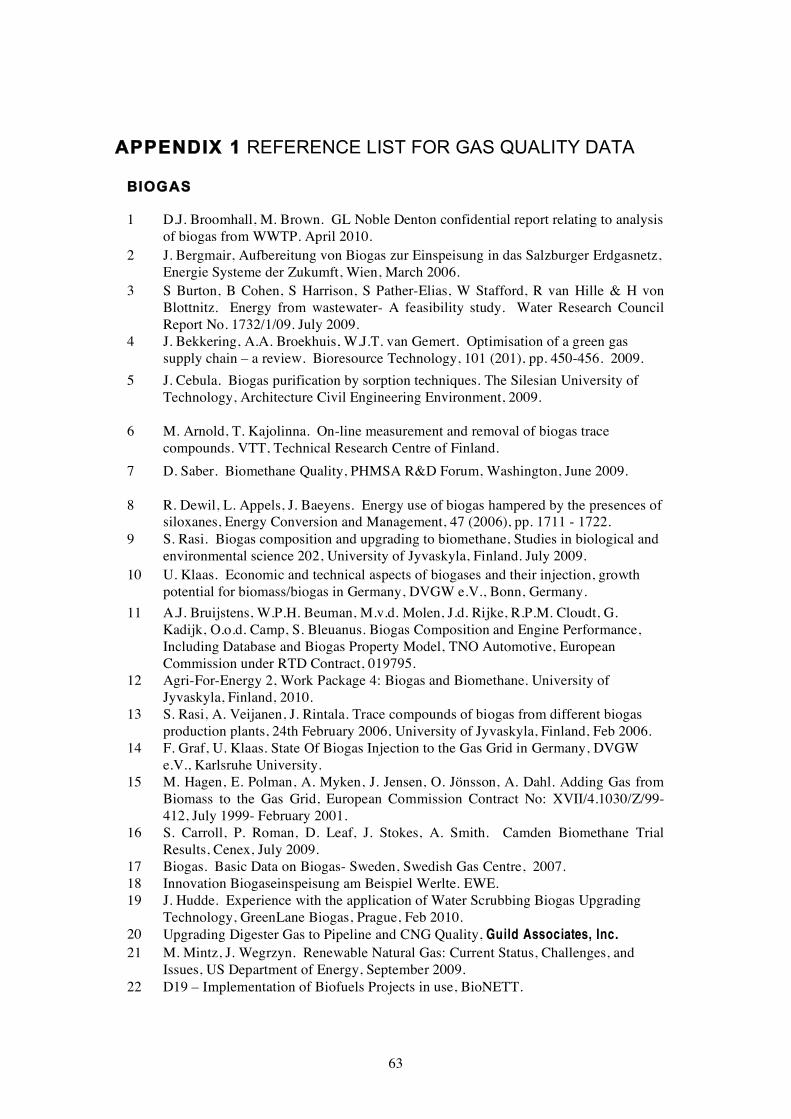
APPENDIX 1 REFERENCE LIST FOR GAS QUALITY DATA
BIOGAS
1 D.J. Broomhall, M. Brown. GL Noble Denton confidential report relating to analysis
of biogas from WWTP. April 2010.
2 J. Bergmair, Aufbereitung von Biogas zur Einspeisung in das Salzburger Erdgasnetz,
Energie Systeme der Zukumft, Wien, March 2006.
3 S Burton, B Cohen, S Harrison, S Pather-Elias, W Stafford, R van Hille & H von
Blottnitz. Energy from wastewater- A feasibility study. Water Research Council
Report No. 1732/1/09. July 2009.
4 J. Bekkering, A.A. Broekhuis, W.J.T. van Gemert. Optimisation of a green gas
supply chain – a review. Bioresource Technology, 101 (201), pp. 450-456. 2009.
5 J. Cebula. Biogas purification by sorption techniques. The Silesian University of
Technology, Architecture Civil Engineering Environment, 2009.
6 M. Arnold, T. Kajolinna. On-line measurement and removal of biogas trace
compounds. VTT, Technical Research Centre of Finland.
7 D. Saber. Biomethane Quality, PHMSA R&D Forum, Washington, June 2009.
8 R. Dewil, L. Appels, J. Baeyens. Energy use of biogas hampered by the presences of siloxanes, Energy Conversion and Management, 47 (2006), pp. 1711 - 1722.
9 S. Rasi. Biogas composition and upgrading to biomethane, Studies in biological and
environmental science 202, University of Jyvaskyla, Finland. July 2009.
10 U. Klaas. Economic and technical aspects of biogases and their injection, growth
potential for biomass/biogas in Germany, DVGW e.V., Bonn, Germany.
11 A.J. Bruijstens, W.P.H. Beuman, M.v.d. Molen, J.d. Rijke, R.P.M. Cloudt, G.
Kadijk, O.o.d. Camp, S. Bleuanus. Biogas Composition and Engine Performance,
Including Database and Biogas Property Model, TNO Automotive, European
Commission under RTD Contract, 019795.
12 Agri-For-Energy 2, Work Package 4: Biogas and Biomethane. University of
Jyvaskyla, Finland, 2010.
13 S. Rasi, A. Veijanen, J. Rintala. Trace compounds of biogas from different biogas
production plants, 24th February 2006, University of Jyvaskyla, Finland, Feb 2006.
14 F. Graf, U. Klaas. State Of Biogas Injection to the Gas Grid in Germany, DVGW
e.V., Karlsruhe University.
15 M. Hagen, E. Polman, A. Myken, J. Jensen, O. Jönsson, A. Dahl. Adding Gas from
Biomass to the Gas Grid, European Commission Contract No: XVII/4.1030/Z/99-
412, July 1999- February 2001.
16 S. Carroll, P. Roman, D. Leaf, J. Stokes, A. Smith. Camden Biomethane Trial
Results, Cenex, July 2009.
17 Biogas. Basic Data on Biogas- Sweden, Swedish Gas Centre, 2007.
18 Innovation Biogaseinspeisung am Beispiel Werlte. EWE.
19 J. Hudde. Experience with the application of Water Scrubbing Biogas Upgrading
Technology, GreenLane Biogas, Prague, Feb 2010.
20 Upgrading Digester Gas to Pipeline and CNG Quality, Guild Associates, Inc. 21 M. Mintz, J. Wegrzyn. Renewable Natural Gas: Current Status, Challenges, and
Issues, US Department of Energy, September 2009.
22 D19 – Implementation of Biofuels Projects in use, BioNETT.
63

BIOGAS
23 Profactor GmbH. Technological and non-technological demands in the different
regions and case environments, European Commission Contract No.
EIE/07/S12.466802, June 2008. 24 D. Thimsen. Distributed Generation and Engines/Turbines for Combustion of
Biogas, EPRI Distributed Energy Resources Program, April 2004
25 G. Pirker. Gas engine solutions for low BTU Applications, CMG, Biogas, Sewage
Gas, LFG to Energy, GE Energy Jenbacher gas engines, New Delhi, March 2010.
26 M. Schweigkofler, R. Niessner. Removal of siloxanes in biogases, Journal of
Hazardous Materials, B83 (2001) 183–196, September 2000.
27 V. Cigolotti. Non-Conventional Waste-Derived Fuels for Molten Carbonate Fuel
Cells, University of Naples, December 2009.
28 N. Johansson. Production of liquid biogas, LBG, with cryogenic and conventional
upgrading technology, Master Thesis, Lunds University, Sweden, December 2008.
29 Brown and Caldwell. Anaerobic Digestion and Combined Heat and Power
Feasibility Study, Massachusetts Board of Public Works, December 2008.
30 P. Seidinger. Biomethane for NGV´s An additional benefit to the environment,
European Gas Forum, Bratislava, September 2008.
31 D. Saber, S. Takach. Technology Investigation, Assessment, and Analysis, GTI
Project Number 20614, September 2009.
32 M. Schmuderer. On the Road with CNG and Biomethane – The “Madegascar”
Project: Overview, operational experience and perspectives of biogas upgrading
technologies, Base Technologies, Prague, February 2010.
33 W. Urban, H. Lohmann. Challenges of Biogas Upgrading to Fuel Cell Quality -
International Workshop on the Effects of Fuel Quality to the Performance of Fuel
Cells, Fraunhofer-Institute UMSICHT9, Berlin, September 2009.
34 Electrigaz Technologies Inc. Feasibility Study – Biogas upgrading and grid injection
in the Fraser Valley, British Columbia, BC Innovation Council, June 2008.
35 S. Mezei. Options for Upgrading Digester Biogas to Pipeline Quality, Flotech
Services, April 2010.
36 T. Ahrens, P. Weiland. Biomethane for future mobility, Landbauforschung
Völkenrode, 2007, 57:71-79. 37 E.A. Hassan. Biogas production from forage and sugar beets: Process Control and
Optimization – Ecology and Economy, University of Kassel, 2003.
38 Federal Agricultural Research Centre of Germany. Demonstration of an optimised
production system for biogas from biological waste and agricultural feedstock,
AGROPTI-Gas, EU-Project NNE5/2000/484, July 2006.
39 C. Riemann. Raw Biogas from Industrial Waste Water, BASF Chemical Company,
personal contact.
64

LANDFILL GAS
1 D.A. de la Rosa, A. Velasco, A. Rosas, T. Volke-Sepúlveda. Total gaseous mercury
and volatile organic compounds measurements at five municipal solid waste disposal
sites surrounding the Mexico City Metropolitan Area, Atmospheric Environment,
2006, 40, 207.
2 T. Parker, J. Dotteridge, S. Kelly. Investigation of the Composition and Emissions of
Trace Components in Landfill Gas, R&D Technical Report P1-438/TR, Environment
Agency, 2002.
3 Biogas – Innovative Ansätze für die Netzeinspeisung, Mittwoch, February 2006,
Wien, Diplomatische Akademie.
4 J. Cebula. Biogas purification by sorption techniques. The Silesian University of
Technology, Architecture Civil Engineering Environment, 2009.
5 M. Arnold, T. Kajolinna. On-line measurement and removal of biogas trace
compounds. VTT, Technical Resarch Centre of Finland.
6 K. Hogg. Canadian Biogas Industry Overview, PTAC Forum, October 2005.
7 R. Dewil, L. Appels, J. Baeyens. Energy use of biogas hampered by the presences of
siloxanes, Energy Conversion and Management, 47 (2006), pp. 1711 - 1722.
8 S. Rasi. Biogas composition and upgrading to biomethane, Studies in biological and
environmental science 202, University of Jyvaskyla, Finland. July 2009.
9 K.A. Adu-Gyamfi, R. Villa, F. Coulon. Renewable Energy, Landfill Gas and EfW:
Now, Next and Future, Cranfield University, UK.
10 U. Klaas. Economic and technical aspects of biogases and their injection, growth
potential for biomass/biogas in Germany, DVGW e.V., Bonn, Germany.
11 M.R. Allen, A. Braithwaite, C.C. Hills. Analysis of the Trace Volatile Organic
Compounds in Landfill Gas Using Automated Thermal Desorption Gas Chromatography-Mass Spectrometry, Nottingham Trent University, International
Journal of Environmental Analytical Chemistry, 62: 1, 43 – 52, 1996.
12 L. Appels, J. Baeyens, J. Degreve, R. Dewil. Principles and potential of the
anaerobic digestion of waste-activated sludge, University of Birmingham, Progress
in Energy and Combustion Science, 34 (2008), pp. 755 - 781.
13 E.A. Polman. Quality Aspects of Green Gas, Kiwa, GT-070127, Netherlands,
September 2007.
14 A.J. Bruijstens, W.P.H. Beuman, M.v.d. Molen, J.d. Rijke, R.P.M. Cloudt, G.Kadijk, O.o.d. Camp, S. Bleuanus. Biogas Composition and Engine Performance,
Including Database and Biogas Property Model, TNO Automotive, European
Commission under RTD Contract, 019795.
15 Agri-For-Energy 2, Work Package 4: Biogas and Biomethane. University of
Jyvaskyla, Finland, 2010.
16 M. Arnold. Reduction and monitoring of biogas trace compounds, 2009, VTT
Tiedotteita – Research Notes 2496, Finland August 2009.
17 Y. Takuwa, T. Matsumoto, K. Oshita, M. Takaoka, S. Morisawa, N. Takeda. Characterisation of trace constituents in landfill gas and a comparison of sites in
Asia, J Mater Cycles Waste Manag (2009) 11:305-311.
18 S. Rasi, A. Veijanen, J. Rintala. Trace compounds of biogas from different biogas production plants, 24th February 2006, University of Jyvaskyla, Finland, Feb 2006.
65

LANDFILL GAS
20 C. Scheutz, J. Bogner, J.P. Chanton, D. Blake, M. Morcet, C. Aran, P. Kjeldsen.
Atmospheric emissions and attenuation of non-methane organic compounds in cover
soils at a French landfill, Waste Management 28 (2008) 1892–1908.
21 M. Hagen, E. Polman, A. Myken, J. Jensen, O. Jönsson, A. Dahl. Adding Gas from
Biomass to the Gas Grid, European Commission Contract No: XVII/4.1030/Z/99-
412, July 1999- February 2001.
22 Biogas. Basic Data on Biogas- Sweden, Swedish Gas Centre, 2007.
23 M. Mintz, J. Wegrzyn. Renewable Natural Gas: Current Status, Challenges, and
Issues, US Department of Energy, September 2009.
24 D. Thimsen. Distributed Generation and Engines/Turbines for Combustion of
Biogas, EPRI Distributed Energy Resources Program, April 2004.
25 E.A. McBean. Siloxanes in biogases from landfills and wastewater digesters, Can. J.
Civ. Eng. 35: 431-436 (2008).
26 G. Pirker. Gas engine solutions for low BTU Applications, CMG, Biogas, Sewage
Gas, LFG to Energy, GE Energy Jenbacher gas engines, New Delhi, March 2010.
27 A.P. Sorurbakhsh, R.J. Onufer, Optimum Gas Quality Specifications – A
Laboratory’s Perspective: What Should It Contain and What Tests Should Be Called
Out, Texas OilTech Laboratories, USA.
28 V. Cigolotti. Non-Conventional Waste-Derived Fuels for Molten Carbonate Fuel
Cells, University of Naples, December 2009.
29 N. Johansson. Production of liquid biogas, LBG, with cryogenic and conventional
upgrading technology, Master Thesis, Lunds University, Sweden, December 2008.
30 M.A. Alex. Sustainable Waste-to-Energy Production: Performance Evaluation of
Distributed Generation fuelled by Landfill Gas, Faculty of Technology of
Lappeenranta University, 2009.
31 W. Urban, H. Lohmann. Challenges of Biogas Upgrading to Fuel Cell Quality -
International Workshop on the Effects of Fuel Quality to the Performance of Fuel
Cells, Fraunhofer-Institute UMSICHT9, Berlin, September 2009.
32 M. Noponen, J. Ruokomäki, J. Paulaharju. Fuel treatment of landfill gas for SOFC, Wartsila, September 2009.
33 T. Parker, J. Hillier, S. Kelly, S. O'Leary. Quantification of trace components in
landfill gas, Environment Agency, UK. December 2004.
66

GASIFICATION
1 M. Sury, M. White, J. Kirton, P. Carr, R. Woodbridge, M. Mostade, R. Chappell, D.
Hartwell, D. Hunt, N. Rendell. Review of Environmental Issues of Underground Coal
Gasification, Report No. COAL R272 DTI/Pub URN 04/1880, November 2004.
2 Cranfield University. Development of Underground Coal Gasification for Power
Generation, Department of Energy and Climate Change, Contract No.
C/07/00378/00/00 URN 09D/679, May 2009.
3 R.W.R. Zwart, H. Boerrigter, E.P. Deurwaarder, C.M. van der Meijden, S.V.B. van
Paasen. Production of Synthetic Natural Gas (SNG) from Biomass, ECN-E-06-018,
November 2006.
4 H. Boerrigter, R. Rauch. Review of applications of gases from biomass gasification,
ECN-RX-06-066, June 2006.
5 R. Rauch. Gas Upgrading from Thermal Gasification, Vienna University of
Technology, Task 37 “Energy from Biogas” Research Exchange Workshop, Biogas
Upgrading, October 2009.
6 C. Pfeifer. Biomass Gasifiers, Vienna University of Technology, Biogas from
Biomass Gasification for Homes and Transport, Gothenburg, January 2010.
7 S. Doong, F. Lau, J. Lin, R. Killmeyer, C. Weinhold, J. Kerr. Low Cost
Hydrogen Production from Biomass Using Novel Membrane Gasification
Reactor, Gas Technology Institute, 2005 DOE Hydrogen Program Review,
Project ID PD13, May 2005. 8 GTI Gasification and Gas Processing R&D Program, ASERTTI 2007.
9 K. Stahl, M. Neergaard, J. Nieminen. Progress Report: Varnamo Biomass
Gasification Plant, 1999 Gasification Technologies Conference, San Francisco,
October 1999.
10 V. Bush. Biomass Gasification: Emerging Technologies for Converting Biomass to
Pipeline-Quality SNG, Gas Technology Institute, Wisconsin Public Utility Institute
Natural Gas Symposium, July 2008.
11 S. Bengtsson. CHRISGAS Syngas Project and the Värnamo Biomass Gasification
Plant, Vaxjo University, Bologna Summer School, September 2009.
12 D.P. Creedy, K. Garner. Clean Energy from Underground Coal Gasification in China,
Report No. COAL R250 DTI/Pub URN 03/1611, Feb 2004.
13 A.Y. Klimenko. Early Ideas in Underground Coal Gasification and Their Evolution,
University of Queensland, Energies 2009, 2, 456-476, June 2009.
14 L. Yulan, L. Xinxing, L. Jie. An overview of the Chinese programme on UCG, China
University of Mining and Technology, Beijing.
15 A. Khadse, M. Qayyumi, S. Mahajani, P. Aghalayam. Underground coal gasification:
A new clean coal utilization technique for India, Department of Chemical
Engineering, IIT Bombay, Mumbai, India.
16 A.L. Lee, H.S. Meyer, A.E. Cover. Test of direct methanation at Rocky Mountain 1 Underground Coal Gasification, Gas Research Institute and M.W. Kellogg Co.
17 P.A. Brownsort. Biomass Pyrolysis Processes: Review of Scope, Control and
Variability, UKBRC Working Paper 5, December 2009.
18 U. Klaas. Economic and technical aspects of biogases and their injection, growth
potential for biomass/biogas in Germany, DVGW e.V., Bonn, Germany.
67

GASIFICATION
19 H. Hofbauer. Fischer-Tropsch-Fuels and Bio-SNG, Vienna University of Technology,
Central European Biomass Conference 2008.
20 U. Zuberbuehler, B. Stuermer, M. Specht, Adjusting methanation Stoichiometry via
AER Process, Center for Solar Energy and Hydrogen Research(ZSW), Baden-
Württemberg, May 2009.
21 S. van Paasen. Advanced gas cleaning, Energy Research Centre of the Netherlands.
22 M. Mozaffarian, R.W.R. Zwart, H. Boerrigter, E.P. Deurwaarder, S.R.A. Kersten.
“Green Gas” as SNG (Synthetic Natural Gas) A Renewable Fuel With Conventional
Quality, ECN-RX--04-085, “Science in Thermal and Chemical Biomass Conversion”
Conference, Victoria, Vancouver Island, BC, Canada, August 2004.
23 M. Hagen, E. Polman, A. Myken, J. Jensen, O. Jönsson, A. Dahl. Adding Gas from
Biomass to the Gas Grid, European Commission Contract No: XVII/4.1030/Z/99-412,
July 1999- February 2001. 24 C. Hackett, T.D. Durbin, W. Welch, J. Pence, R.B. Williams, B.M. Jenkins, D. Salour,
R. Aldas. Evaluation of Conversion Technology Processes and Products, University
of California, California Integrated Waste Management Board, September 2004. 25 V. Cigolotti. Non-Conventional Waste-Derived Fuels for Molten Carbonate Fuel
Cells, University of Naples, December 2009.
26 M. Mozaffarian, R.W.R. Zwart. Feasibility of Biomass/Waste-related SNG
Production Technologies, ECN-C--03-066, July 2003.
68

COAL-MINE CH4, COAL-BED CH4 AND SHALE GAS
1 A.G. Kim. The Composition of Coalbed Gas. Pittsburgh Mining and Safety
Research Centre, Report of Investigations 7762, 1973.
2 T. Gentzis, F. Goodarzi, F.K. Cheung, F. Laggoun-Defarge. Coalbed methane
producibility from the Mannville coals in Alberta, Canada: A Comparison of Two
Areas.
3 L. Bingyan, S. Shengling. Utilization of Coal-bed Methane and Oilfield
Associate Gas in Carbon Black Industry, China Carbon Black Institute.
4 H. Hosgormez. Origin and secondary alteration of coalbed and adjacent rock
gases in the Zonguldak Basin, western Black Sea Turkey, Geochemical Journal,
Vol 41, pp 201-211, 2007.
5 Coal bed methane compositions, private communication from Composite Energy.
6 R.C. Collings. Case study: Long Term Abandoned Mine Methane Recovery
Operation in the US, Ruby Canyon Engineering, January 2009.
8 Caterpillar. Sustainable Green Electricity From Coal Gas in China, Overview of a 120 MW Coal Mine Methane Cogeneration Power Project in PRC, June 2008.
9 Power Generation. Mining Magazine special publication. Energy to burn: coal
mine gas, September 2008.
10 U. Klaas. Economic and technical aspects of biogases and their injection, growth
potential for biomass/biogas in Germany, DVGW e.V., Bonn, Germany.
11 http://www.bhkw-infozentrum.de/req/grubengas_entstehung.html
12 http://www.pem-oberhausen.de/englisch/motivation/grubgas.html
13 G. Pirker. Gas engine solutions for low BTU Applications, CMG, Biogas,
Sewage Gas, LFG to Energy, GE Energy Jenbacher gas engines, New Delhi,
March 2010. 16 A. Dicks, T. Connor, J. Bradley, A. Lashtabeg. Impact of Australian natural gas
and coal bed methane composition on PEM fuel cell performance, International
Journal of Hydrogen Energy XXX 1-13, 2009.
17 Analysis of coal mine gas from Hyder Industrial Ltd. Cardiff, Tower Colliery,
Private communication, Sept 2000.
18 P. Cole, C. Robinson, D. Robson. An assessment of the potential use of mines
gas as an alternative supply of distributed gas, Confidential Advantica report
R4056, Nov 2000.
19 DTI. Coalbed Methane Extraction and Utilisation, Technology Status Report
016, August 2001.
69

Published by the Health and Safety Executive 11/11

Health and Safety Executive
Hazards arising from the conveyance and use of gas from Non-Conventional Sources (NCS)
The Health and Safety Executive (HSE) recognises that there is increasing interest in the use of non-conventional source (NCS) gases and that conveyance of the gas from the source to the end user will be through the existing natural gas grid. All gas transported and used has to comply with the Gas Safety (Management) Regulations [GS(M)R] and this raises questions with regard to the suitability of the NCS gas within the network and the possible additional hazards that may result over and above those associated with natural gas.
The HSE commissioned this study to review the available data on NCS gas composition to support assessment of hazards and risks associated with the introduction of NCS gas into pipeline networks.
This report covers the following aspects:
� Collation of data on composition for a range of NCS gas types and sources, including both bulk gas components and contaminants.
� Summary of NCS gas clean-up processes and their performance with regard to removal of contaminants.
� Impact of NCS gas composition on network materials, combustion/utilisation equipment and emissions.
The majority of compounds found in NCS gas are similar to those found in natural gas and thus pose no greater risk to the integrity of the pipeline and downstream equipment, however, siloxanes, high levels of oxygen and highly odiferous compounds need further study.
This report and the work it describes were funded by the Health and Safety Executive (HSE). Its contents, including any opinions and/or conclusions expressed, are those of the authors alone and do not necessarily reflect HSE policy.
RR882
www.hse.gov.uk