IFC 42/2014 Open Spectrum Submission - Home | ACMA/media/Spectrum Monitoring and Analysis... · 3...
38
IFC 42/2014 Open Spectrum Submission Proposed updates to RALI LM8 land mobile service frequency assignment requirements 3 NOVEMBER 2014
Transcript of IFC 42/2014 Open Spectrum Submission - Home | ACMA/media/Spectrum Monitoring and Analysis... · 3...

IFC 42/2014 Open Spectrum
Submission Proposed updates to RALI
LM8 land mobile service frequency assignment
requirements
3 NOVEMBER 2014

Open Spectrum Pty Ltd 1
1 Introduction Open Spectrum thanks the ACMA for consulting on the draft update to RALI LM 8, and appreciates the opportunity to provide comments. Open Spectrum also appreciates the ACMA’s thorough work on the RALI update and Spectrum Planning Report SPP 08/14 (SPP 08/14). SPP 08/14 was a particularly helpful aid in industry’s consideration of the draft update to RALI LM 8.
Open Spectrum agrees with the proposed updates to RALI LM 8, particularly:
• definition of a service model for sited ambulatory systems • addition of height/power restrictions to reduce spectrum denial of high power services • requirement to perform frequency coordination for supplementary transmitters to
ensure that these don’t result in unexpected interference • reduction of frequency cull limit from ±1.2 MHz to ±112.5 kHz and ±25 kHz for the
400 MHz and 800 MHz bands, respectively • addition of frequency-distance constraints for 6.25 kHz systems and for coordinating
land mobile radio systems (LMRS) with low power mobile radio systems (LPMRS) • clarification of application of frequency-distance culls for intermodulation checks.
Open Spectrum offers further comments on the following issues:
• More flexible and clearly-defined requirements of detailed case-by-case coordination for land mobile systems are likely to allow more efficient use of land mobile spectrum.
• The frequency-distance constraint tables in Annex C to RALI LM 8 could benefit from clarification of their applicability, with a view to avoiding unnecessary or unintended application of multiple tables to certain scenarios.
• Clarification on some aspects of the calculation of frequency-distance constraints would provide a better understanding of how the latter were derived and how they can be applied. These aspects include:
o addition of base station (BS) RF selectivity in link budget o frequency edges of emission masks and receiver selectivity masks o addition of propagation correction factors o Point 3 under “Additional adjustments for two-frequency systems”
• Some frequency-distance constraints for single-frequency LMRS are proposed to be modified or at least considered further, given that Open Spectrum identified some discrepancies between Tables C2 and C3 and calculations according to the ACMA’s methodology in SPP 08/14. Open Spectrum reserves comment on frequency-distance constraints for two-frequency systems pending clarification of the points listed above.
• Correction of the BS RF selectivity is proposed for the VHF Mid and High Bands. • The specification of the Modified Hata Model from ERC Report 068 for both LMRS and
LPMRS could be consolidated to avoid unnecessary repetition. • Some references proposed to be deleted from the Bibliography are useful sources of
information and are proposed to be retained. • Definition of coordination requirements and procedures to protect Telstra wide band
fixed links in 500-520 MHz is likely to make the frequency assignment process clearer and simpler.
Specific requests for the ACMA to consider a proposal or provide clarification are written in bold and outlined.
Open Spectrum Pty Ltd 2
Contact Juan Pablo Casetta
Director | Open Spectrum Pty Ltd
P: (02) 6299 2948
W: www.openspec.com.au
Open Spectrum Pty Ltd 3
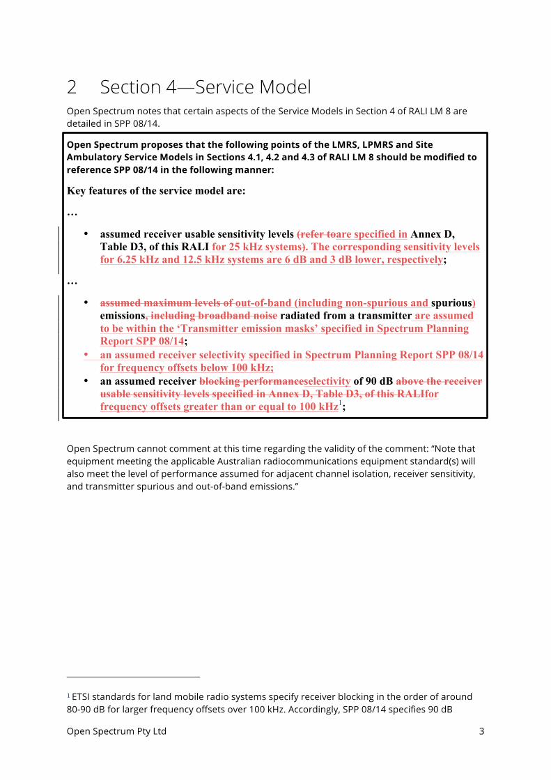
2 Section 4—Service Model Open Spectrum notes that certain aspects of the Service Models in Section 4 of RALI LM 8 are detailed in SPP 08/14.
Open Spectrum proposes that the following points of the LMRS, LPMRS and Site Ambulatory Service Models in Sections 4.1, 4.2 and 4.3 of RALI LM 8 should be modified to reference SPP 08/14 in the following manner:
Key features of the service model are:
…
• assumed receiver usable sensitivity levels (refer toare specified in Annex D, Table D3, of this RALI for 25 kHz systems). The corresponding sensitivity levels for 6.25 kHz and 12.5 kHz systems are 6 dB and 3 dB lower, respectively;
…
• assumed maximum levels of out-of-band (including non-spurious and spurious) emissions, including broadband noise radiated from a transmitter are assumed to be within the ‘Transmitter emission masks’ specified in Spectrum Planning Report SPP 08/14;
• an assumed receiver selectivity specified in Spectrum Planning Report SPP 08/14 for frequency offsets below 100 kHz;
• an assumed receiver blocking performanceselectivity of 90 dB above the receiver usable sensitivity levels specified in Annex D, Table D3, of this RALIfor frequency offsets greater than or equal to 100 kHz1;
Open Spectrum cannot comment at this time regarding the validity of the comment: “Note that equipment meeting the applicable Australian radiocommunications equipment standard(s) will also meet the level of performance assumed for adjacent channel isolation, receiver sensitivity, and transmitter spurious and out-of-band emissions.”
1 ETSI standards for land mobile radio systems specify receiver blocking in the order of around 80-90 dB for larger frequency offsets over 100 kHz. Accordingly, SPP 08/14 specifies 90 dB
Open Spectrum Pty Ltd 4
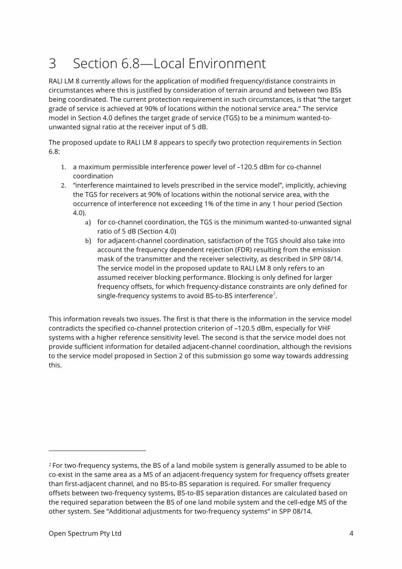
3 Section 6.8—Local Environment RALI LM 8 currently allows for the application of modified frequency/distance constraints in circumstances where this is justified by consideration of terrain around and between two BSs being coordinated. The current protection requirement in such circumstances, is that “the target grade of service is achieved at 90% of locations within the notional service area.” The service model in Section 4.0 defines the target grade of service (TGS) to be a minimum wanted-to-unwanted signal ratio at the receiver input of 5 dB.
The proposed update to RALI LM 8 appears to specify two protection requirements in Section 6.8:
1. a maximum permissible interference power level of –120.5 dBm for co-channel coordination
2. “interference maintained to levels prescribed in the service model”, implicitly, achieving the TGS for receivers at 90% of locations within the notional service area, with the occurrence of interference not exceeding 1% of the time in any 1 hour period (Section 4.0).
a) for co-channel coordination, the TGS is the minimum wanted-to-unwanted signal ratio of 5 dB (Section 4.0)
b) for adjacent-channel coordination, satisfaction of the TGS should also take into account the frequency dependent rejection (FDR) resulting from the emission mask of the transmitter and the receiver selectivity, as described in SPP 08/14. The service model in the proposed update to RALI LM 8 only refers to an assumed receiver blocking performance. Blocking is only defined for larger frequency offsets, for which frequency-distance constraints are only defined for single-frequency systems to avoid BS-to-BS interference2.
This information reveals two issues. The first is that there is the information in the service model contradicts the specified co-channel protection criterion of –120.5 dBm, especially for VHF systems with a higher reference sensitivity level. The second is that the service model does not provide sufficient information for detailed adjacent-channel coordination, although the revisions to the service model proposed in Section 2 of this submission go some way towards addressing this.
2 For two-frequency systems, the BS of a land mobile system is generally assumed to be able to co-exist in the same area as a MS of an adjacent-frequency system for frequency offsets greater than first-adjacent channel, and no BS-to-BS separation is required. For smaller frequency offsets between two-frequency systems, BS-to-BS separation distances are calculated based on the required separation between the BS of one land mobile system and the cell-edge MS of the other system. See “Additional adjustments for two-frequency systems” in SPP 08/14.
Open Spectrum Pty Ltd 5
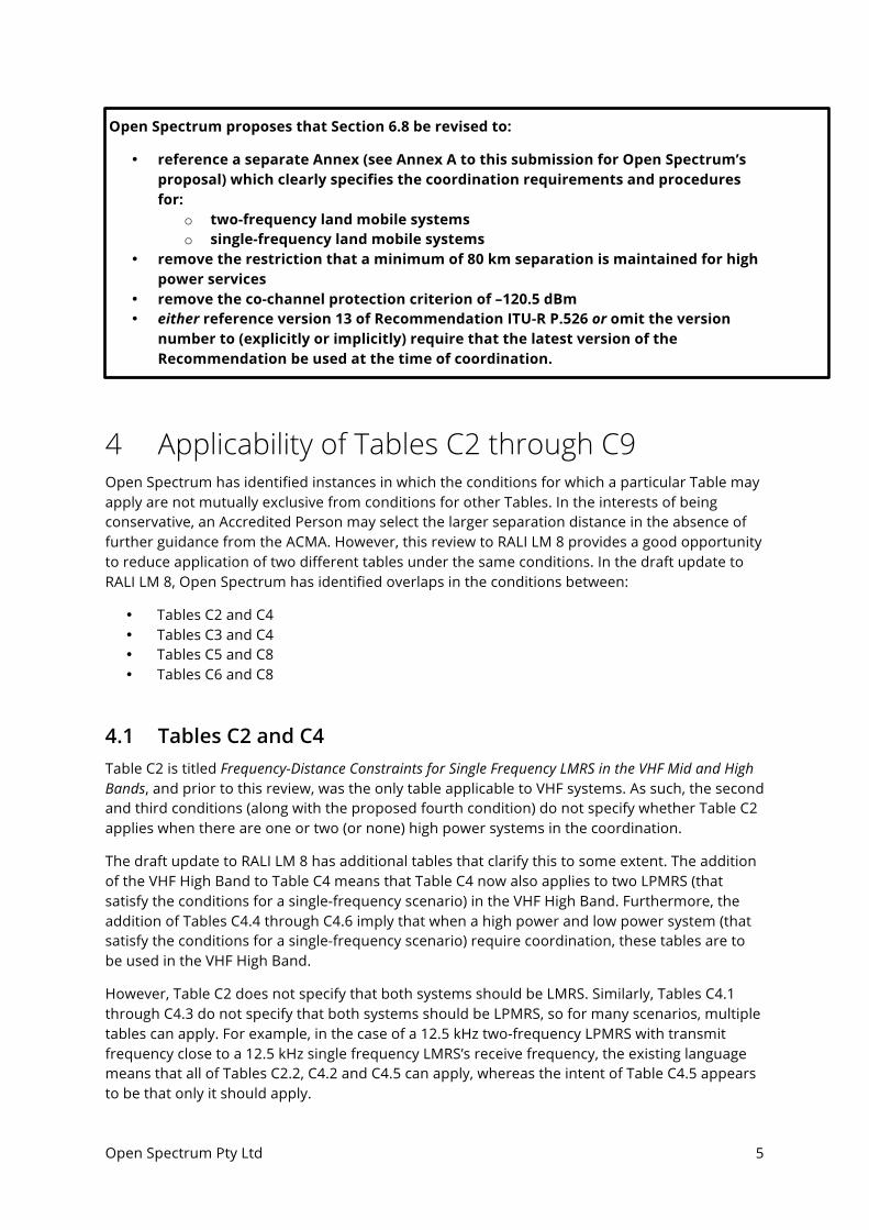
Open Spectrum proposes that Section 6.8 be revised to:
• reference a separate Annex (see Annex A to this submission for Open Spectrum’s proposal) which clearly specifies the coordination requirements and procedures for:
o two-frequency land mobile systems o single-frequency land mobile systems
• remove the restriction that a minimum of 80 km separation is maintained for high power services
• remove the co-channel protection criterion of –120.5 dBm • either reference version 13 of Recommendation ITU-R P.526 or omit the version
number to (explicitly or implicitly) require that the latest version of the Recommendation be used at the time of coordination.
4 Applicability of Tables C2 through C9 Open Spectrum has identified instances in which the conditions for which a particular Table may apply are not mutually exclusive from conditions for other Tables. In the interests of being conservative, an Accredited Person may select the larger separation distance in the absence of further guidance from the ACMA. However, this review to RALI LM 8 provides a good opportunity to reduce application of two different tables under the same conditions. In the draft update to RALI LM 8, Open Spectrum has identified overlaps in the conditions between:
• Tables C2 and C4 • Tables C3 and C4 • Tables C5 and C8 • Tables C6 and C8
4.1 Tables C2 and C4 Table C2 is titled Frequency-Distance Constraints for Single Frequency LMRS in the VHF Mid and High Bands, and prior to this review, was the only table applicable to VHF systems. As such, the second and third conditions (along with the proposed fourth condition) do not specify whether Table C2 applies when there are one or two (or none) high power systems in the coordination.
The draft update to RALI LM 8 has additional tables that clarify this to some extent. The addition of the VHF High Band to Table C4 means that Table C4 now also applies to two LPMRS (that satisfy the conditions for a single-frequency scenario) in the VHF High Band. Furthermore, the addition of Tables C4.4 through C4.6 imply that when a high power and low power system (that satisfy the conditions for a single-frequency scenario) require coordination, these tables are to be used in the VHF High Band.
However, Table C2 does not specify that both systems should be LMRS. Similarly, Tables C4.1 through C4.3 do not specify that both systems should be LPMRS, so for many scenarios, multiple tables can apply. For example, in the case of a 12.5 kHz two-frequency LPMRS with transmit frequency close to a 12.5 kHz single frequency LMRS’s receive frequency, the existing language means that all of Tables C2.2, C4.2 and C4.5 can apply, whereas the intent of Table C4.5 appears to be that only it should apply.

Open Spectrum Pty Ltd 6
Open Spectrum’s understanding is as follows for two systems in the VHF High Band that satisfy the conditions for a single-frequency scenario:
• Table C2 is based on a high-power, high-site BS transmitter interfering with a high-site BS receiver, and uses the Modified Longley-Rice propagation model as specified in Table 12 of SPP 08/14. Table C2 is to be used when both systems are high power LMRS.
• Tables C4.4 through C4.6 are based on a high-power, high-site BS transmitter interfering with a low-site BS receiver3. Tables C4.4 through C4.6 are to be used when one system is high power LMRS and the other is low power LPMRS.
• Tables C4.1 through C4.3 are based on low-power, low-site BS transmitter interfering with a low-site BS receiver. Tables C4.1 through C4.3 are to be used when both systems are low power LPMRS.
Open Spectrum requests that the ACMA confirm its understanding in the dot points above, and consider the proposed modifications to the conditions for Tables C2 and C4 (see Annex C to this submission) to provide clearer guidance on their applicability.
4.2 Tables C3 and C4 The same issues exist with Table C3—the second and third conditions do not specify whether Table C3 applies for one or two high power systems in the coordination. It is safe to assume that when both systems are LPMRS in the 400 MHz band, Table C4 applies.
The addition of Tables C4.7 through C4.9 imply that when a high power and low power system (that satisfy the conditions for a single-frequency scenario) require coordination, these tables are to be used in the 400 MHz band.
Open Spectrum’s understanding is as follows for two systems in the 400 MHz Band that satisfy the conditions for a single-frequency scenario:
• Table C3 is to be used when both systems are high power LMRS. • Tables C4.7 through C4.9 are to be used when one system is high power LMRS and the other
is low power LPMRS. • Tables C4.1 through C4.3 are to be used when both systems are low power LPMRS.
Open Spectrum requests that the ACMA confirm its understanding in the dot points above, and consider the proposed modifications to the conditions for Tables C3 and C4 (see Annex C to this submission) to provide clearer guidance on their applicability.
3 SPP 08/14 clearly states: “The following frequency-distance values apply whenever high and low power single-frequency systems in the 400 MHz band are to be coordinated. The distance values shown below in the tables are the worst case values (comparing LMRS transmitter into LPMRS receiver, and LPMRS transmitter into LMRS receiver). In single frequency systems, the worst case scenario was always LMRS into LPMRS.” This case is a high-power, high-site BS transmitter interfering with a low-site BS receiver, using the Modified Hata (urban) model.
Open Spectrum Pty Ltd 7
4.3 Tables C5 and C8 Table C5 does not currently specify the conditions for which it applies. Open Spectrum assumes that the conditions for Table C6 could be used for Table C5, the only difference being the frequency band of applicability. That being the case, for the VHF High Band, both Tables C5 and C8 would apply when one two-frequency system is high power and the other is low power.
The addition of Table C8 implies that when a high power and low power system (that satisfy the conditions for a two-frequency scenario) require coordination, Table C8 is to be used.
Open Spectrum’s understanding is as follows for two systems that satisfy the conditions for a two-frequency scenario in the VHF High Band:
• Table C5 is to be used when both systems are high power LMRS. • Table C8 is to be used when one system is high power LMRS and the other is low power
LPMRS. • Table C7 is to be used when both systems are low power LPMRS.
Open Spectrum requests that the ACMA confirm its understanding in the dot points above, and consider the proposed modifications to the conditions for Tables C5 and C8 (see Annex C to this submission) to provide clearer guidance on their applicability.
4.4 Tables C6 and C8 The same issue exists with Table C6—for the 400 MHz Band, both Tables C6 and C8 would apply when one two-frequency system is high power and the other is low power.
The addition of Table C8 implies that when a high power and low power system (that satisfy the conditions for a two-frequency scenario) require coordination, Table C8 is to be used.
Open Spectrum’s understanding is as follows for two systems that satisfy the conditions for a two-frequency scenario in the 400 MHz Band:
• Table C6 is to be used when both systems are high power LMRS. • Table C8 is to be used when one system is high power LMRS and the other is low power
LPMRS. • Table C7 is to be used when both systems are low power LPMRS.
Open Spectrum requests that the ACMA confirm its understanding in the dot points above, and consider the proposed modifications to the conditions for Tables C6 and C8 (see Annex C to this submission) to provide clearer guidance on their applicability.
4.5 Table C7 Following from the dot points above, Open Spectrum believes that Table C7 needs to specify that both systems must be LPMRS.
Open Spectrum requests that the ACMA consider the proposed modifications to the conditions for Table C7 (see Annex C to this submission).

Open Spectrum Pty Ltd 8
4.6 Scenarios for which no tables apply Open Spectrum has identified the following scenarios for which no there are no dedicated tables in the VHF Mid Band:
• Two single-frequency LPMRS—assuming Table C2 applies, but this is overly-conservative. • Two two-frequency LPMRS with the same frequency sense—assuming Table C5 applies,
but this is overly-conservative.
Open Spectrum understands that these scenarios are of low likelihood given the small proportion of LPMRS in the VHF Mid Band, and can be dealt with on a case-by-case basis if necessary.
5 Base Station receiver frequency response Open Spectrum has identified some issues with base station receiver frequency response, which is comprised of two separate components:
• ‘receiver selectivity’—defined on pages 14-16 of SPP 08/14 • ‘RF selectivity’—defined in Table 1 (page 7) of SPP 08/14 and Table D3 of the draft update
to RALI LM 8
5.1 Correction of VHF RF selectivity Annex D to this contribution displays discontinuities identified by Open Spectrum in the RF selectivity for the VHF Mid and High Bands calculated according to Table 1 (page 7) of SPP 08/14 and Table D3 of the draft update to RALI LM 8.
Open Spectrum proposes the following modifications to Table 1 (page 7) of SPP 08/14 and Table D3 of the draft update to RALI LM 8:
RF (receiver front-end response: achieved by the RF selectivity of a receiver in conjunction with two cavity filters)
For the VHF Mid and High Bands: 2 dB for Freq Offset <= 0.06 MHz 2 x [23.3 + 18.7*log(Freq Offset)] dB for 0.060.064 < Freq Offset <= 1.5 MHz 2 x [23.3 + 18.7*log(Freq Offset) + (Freq Offset – 1.5)*18/1.5] dB for 1.5 MHz < Freq Offset <= 4.4 MHz 70 140 dB for Freq Offset > 4.4 MHz …
Open Spectrum identified similar discontinuities for the 400 MHz and 800 MHz band RF selectivity curves, but these are for much larger frequency offsets not considered in the frequency-distance constraints in RALI LM 8 and can be ignored.
Open Spectrum Pty Ltd 9
5.2 Addition of RF selectivity to FDR SPP 08/14, pages 20 through 23, specifies the methodology used to calculate the frequency-distance constraints in the draft update to RALI LM 8. The distance in these constraints is the minimum distance between interfering BS and victim receiver such that the interference level at the latter does not exceed the maximum acceptable interference level, noting some exceptions for two-frequency systems. Equation 2 is:
Pr = EIRP + Gr – Lpath – FDR – Selrx
where FDR is frequency dependent rejection and Selrx is the base station front-end response achieved by the RF selectivity of the receiver (0 dB for two-frequency systems).
There are two issues with the subtraction of Selrx in Equation 2.
a) Conceptually, arithmetic addition of RF selectivity to FDR, of which receiver frequency response is an input, is incorrect. This is explained in Annex E to this contribution.
b) Insertion loss of the cavity filters (e.g. 2 dB in the VHF Mid and High Bands and 5 dB in the 400 MHz Band) cannot be used to reduce the interfering signal level, since insertion loss also reduces the wanted signal level.
To address Issue (a) above, Open Spectrum requests that SPP 08/14 be revised to clarify that:
Selrx : Base station front-end response achieved by the RF selectivity of the receiver (0 dB for two-frequency systems). Normally, Selrx should be added to receiver selectivity in Figures 6 through 8, which is then used to calculate FDR. In this case, Selrx is added arithmetically to FDR for simplicity. The on-set of additional RF attenuation at larger frequency offsets (at least 60 kHz) in Selrx reduces the discrepancy between the two methods.
SPP 08/14 will be a valuable reference in future to ACMA staff and members of the radiocommunications industry alike, and so Open Spectrum believes this clarification will help to avoid confusion for future readers.
To address Issue (b) above, Open Spectrum requests that the ACMA advise whether the insertion loss of the cavity filter was subtracted in the calculation of Pr in Equation 2 of SPP 08/14.

Open Spectrum Pty Ltd 10
5.3 Frequency edges of receiver selectivity masks Furthermore, Open Spectrum seeks clarification on what the frequency edges of the masks were in the development of frequency-distance constraints. SPP 08/14, page 23 states: “Beyond the edges of the masks specified by the user: rather than a roll-off, the response is assumed to drop to zero (i.e. –∞ dB)”.
If the emission spectrum P(f) and receiver frequency response H(f) are assumed to be –∞ dB past the frequency edge at x kHz, then the resulting FDR is ∞ dB for frequency offsets greater than 2x kHz.
The only tables for which there are non-zero frequency-distance constraints beyond 100 kHz are for single frequency LMRS in the VHF Mid and High Bands. For these tables, the required separation distance, and hence the FDR, does not change between 103.75 kHz and 1200 kHz, which makes it unclear as to whether and how Selrx was indeed applied.
6 Clarification of frequency-distance constraint calculations
6.1 Addition of propagation correction factors The Modified Hata Model is described in detail in Annex A2 of RALI LM 8. However, the following sentence adds ambiguity to calculation of propagation path loss in the derivation of frequency-distance constraints:
“The modified Hata model estimates mean propagation loss (50% of locations for 50% of the time). A correction factor of 11 dB has been applied to convert the loss to be applicable for 90% of locations [14]. Also a correction factor of 4 dB has been applied to convert the loss to be applicable for 1% of the time [14].”
It is not entirely clear whether one or both factors have been added to wanted signal propagation path loss calculations, nor whether one or both factors have been subtracted from interfering signal propagation path loss calculations. These factors should not be added to interfering signal propagation path loss calculations, since this effectively uses time and location variability to underestimate interference signal level, which is incorrect.
Open Spectrum seeks clarification on the application of the propagation correction factors mentioned in Annex A2 of RALI LM 8.
If these factors have been applied only to wanted signal calculations, such propagation correction factors are typically added to a minimum wanted signal level (i.e. reference sensitivity) to derive a minimum median wanted signal level (i.e. desired signal level)—see Section 3.2.2 of Annex 2 to Recommendation ITU-R SM.337-6. Such a clarification could easily be incorporated in RALI LM 8.
If these factors have been applied (either added or subtracted) to interfering signal propagation path loss calculations, further discussion may be required.
Open Spectrum Pty Ltd 11
6.2 Additional adjustments for two-frequency systems Point 3 under “Additional adjustments for two-frequency systems” in SPP 08/14 appears to refer a methodology by which “a threshold distance [is] chosen to achieve the target grade of service for mobile station receivers at 90% of locations within the notional service area of a land mobile system” for non-co-channel land mobile systems. However, the methodology is not described.
Open Spectrum seeks clarification on the methodology by which a threshold distance is chosen to achieve a target grade of service for mobile station receivers at 90% of locations.
6.3 Repetition of the Modified Hata Model In Annex A2 of the draft update to RALI LM 8, the urban path loss calculation of the Modified Hata Model is defined twice:
• for LMRS, a slightly simplified model based on the assumption that hb ≥ 30 m, hm ≤ 10 m and f ≥ 150 MHz
• for LPMRS, a general model allowing hb < 30 m, hm > 10 m and f < 150 MHz
Open Spectrum proposes that this repetition of the Modified Hata Model urban path loss calculation be removed. See Annex F for a specific proposal.
7 Frequency-distance constraints for single-frequency LMRS Open Spectrum has reproduced frequency-distance constraints for equal-bandwidth single-frequency LMRS. While there is general alignment between the results, some significant differences have been identified between the reproduced frequency-distance constraints and those in Tables C2 and C3 of the draft update to RALI LM 8. See Annex G for details.
For the time being, Open Spectrum wishes to make the following specific proposals:
• Open Spectrum proposes that the co-channel separation distance of 140 km be retained for single-frequency LMRS in the 400 MHz band. This affects the LMRS Service Model in Section 4.1 and Table C3 of RALI LM 8.
• Open Spectrum proposes that, for frequency offsets greater than 100 kHz, Table C2 should either:
o not be revised (i.e. retain values from the existing RALI LM 8); or o be revised to require 0 km separation as for the 400 MHz band.
Furthermore, Open Spectrum has identified other discrepancies between its calculations and the values in Tables C2 and C3 of RALI LM 8. Pending further clarification on calculations for two-frequency systems and LPMRS, further refinements could be made to the Tables in the draft update to RALI LM 8.
Open Spectrum would be pleased to work with the ACMA to work on frequency-distance constraints prior to final release of the updated RALI.

Open Spectrum Pty Ltd 12
8 RALI LM 8 Bibliography Open Spectrum notes that the following references are proposed to be deleted in the draft update to RALI LM 8:
1. ‘Frequency Assignment Strategies in Australia’, M.J. Whittaker, SMIREE; Journal of Electrical and Electronics Engineering Australia - IE Aust and IREE Aust, Vol 11 No. 3, September 1991.
2. ‘Determining Necessary Adjacent Channel Isolation and Re-use Distance for a Radiocommunication Service’, M.J. Whittaker, SMIREE; Journal of Electrical and Electronics Engineering Australia - IE Aust and IREE Aust, Vol 10 No. 4, December 1990.
3. ‘Minimisation of Intermodulation Interference in Trunked Land Mobile Systems’, Spectrum Planning Report No. 10/91, Spectrum Management Agency, August 1991.
4. ‘Channel Arrangements for the Trunked Land Mobile Segments of the VHF Mid and High Band Plans’, Spectrum Planning Report No. 11/91, Spectrum Management Agency June 1991.
5. ‘VHF High Band Trunking: Minimum Geographical Separation Between Trunking Sites’, Spectrum Planning Report No. 14/91, Spectrum Management Agency, July 1991.
6. ‘A Guide to the Use of the ITS Irregular Terrain Model in the Area Prediction Mode’, G.A. Hufford, A.G. Longley and W.A. Kissick, NTIA Report 82-100, April 1982.
Some of these references provide useful information on, for example:
• SPP 14/91—the background of the 200 m separation, above which intermodulation interference is considered to be minimised, and below which interference issues are considered a matter of site management (e.g. in spectrum licence technical frameworks)
• SPP 10/91 and 11/91—the background on co-site channel separation to minimise intermodulation interference.
• NTIA Report 82-100—the background of the free space loss plus 10 dB propagation model.
Open Spectrum proposes that these references be retained if it is not necessary to delete them.

Open Spectrum Pty Ltd 13
9 Telstra 500 MHz Wideband Fixed Services Annex E2 to the proposed update to RALI LM 8 refers to coordination requirements that ‘may apply’ for assignments within 400 km of wideband fixed services in 500-520 MHz—Open Spectrum understands these are point-to-multipoint high capacity radio concentrator (HCRC) systems. The map below depicts areas within 400 km of these licensed services, and shows that there are limited areas in which these coordination requirements would definitely not apply. Admittedly, the Mt Cann site in south eastern Victoria presents a very particular scenario, both in its proximity to high-use areas and surrounding terrain.
As a company with Accredited Persons, Open Spectrum believes that ‘contacting the Manager of Spectrum Engineering’ for every assignment in 500-520 MHz within 400 km of wideband fixed services in 500-520 MHz—i.e. the coloured areas in the map—is not practical.
As such, Open Spectrum proposes that these coordination requirements be developed and made available for use by Accredited Persons. Open Spectrum would be pleased to work with the ACMA and service users to develop such arrangements.
Open Spectrum Pty Ltd 14
References [1] Draft RALI LM 8 Update
[2] Spectrum Planning Report SPP 08/14—Derivation of 400 MHz band land mobile frequency-distance constraints used in RALI LM 8
Open Spectrum Pty Ltd 15
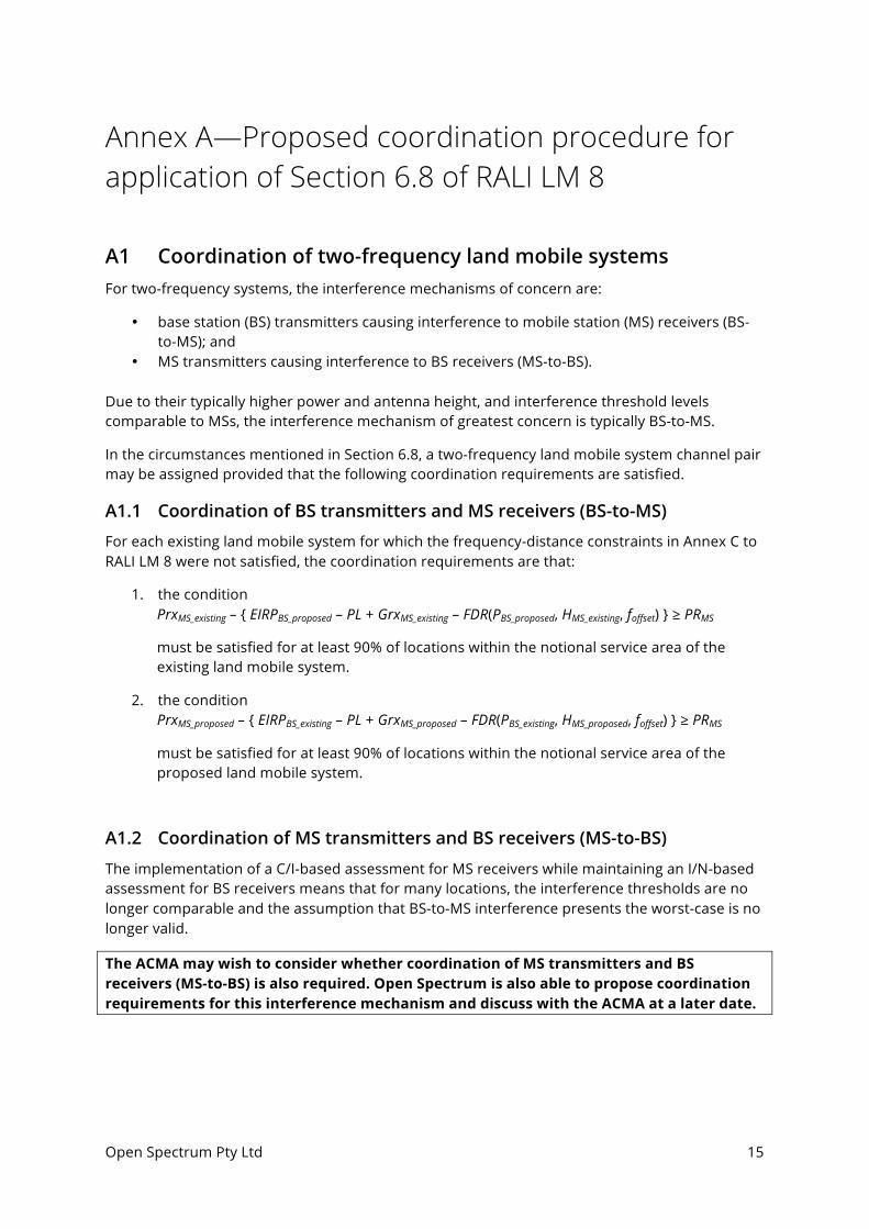
Annex A—Proposed coordination procedure for application of Section 6.8 of RALI LM 8
A1 Coordination of two-frequency land mobile systems For two-frequency systems, the interference mechanisms of concern are:
• base station (BS) transmitters causing interference to mobile station (MS) receivers (BS-to-MS); and
• MS transmitters causing interference to BS receivers (MS-to-BS).
Due to their typically higher power and antenna height, and interference threshold levels comparable to MSs, the interference mechanism of greatest concern is typically BS-to-MS.
In the circumstances mentioned in Section 6.8, a two-frequency land mobile system channel pair may be assigned provided that the following coordination requirements are satisfied.
A1.1 Coordination of BS transmitters and MS receivers (BS-to-MS)
For each existing land mobile system for which the frequency-distance constraints in Annex C to RALI LM 8 were not satisfied, the coordination requirements are that:
1. the condition PrxMS_existing – { EIRPBS_proposed – PL + GrxMS_existing – FDR(PBS_proposed, HMS_existing, foffset) } ≥ PRMS
must be satisfied for at least 90% of locations within the notional service area of the existing land mobile system.
2. the condition PrxMS_proposed – { EIRPBS_existing – PL + GrxMS_proposed – FDR(PBS_existing, HMS_proposed, foffset) } ≥ PRMS
must be satisfied for at least 90% of locations within the notional service area of the proposed land mobile system.
A1.2 Coordination of MS transmitters and BS receivers (MS-to-BS)
The implementation of a C/I-based assessment for MS receivers while maintaining an I/N-based assessment for BS receivers means that for many locations, the interference thresholds are no longer comparable and the assumption that BS-to-MS interference presents the worst-case is no longer valid.
The ACMA may wish to consider whether coordination of MS transmitters and BS receivers (MS-to-BS) is also required. Open Spectrum is also able to propose coordination requirements for this interference mechanism and discuss with the ACMA at a later date.
Open Spectrum Pty Ltd 16
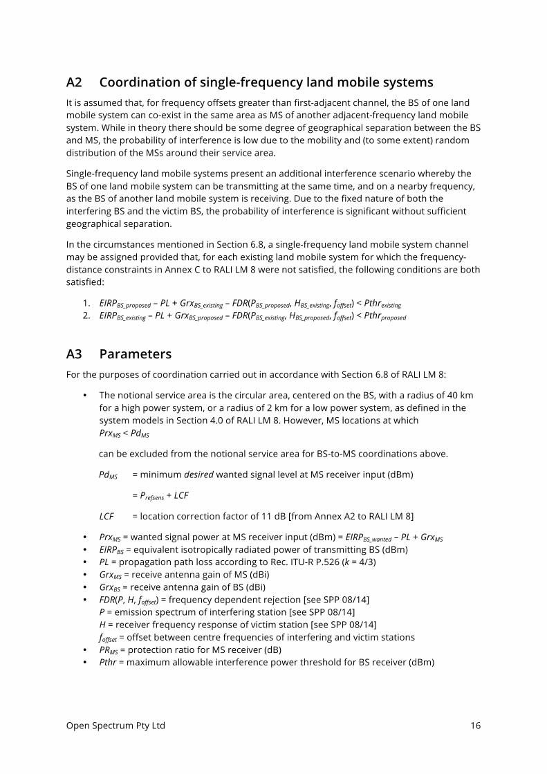
A2 Coordination of single-frequency land mobile systems It is assumed that, for frequency offsets greater than first-adjacent channel, the BS of one land mobile system can co-exist in the same area as MS of another adjacent-frequency land mobile system. While in theory there should be some degree of geographical separation between the BS and MS, the probability of interference is low due to the mobility and (to some extent) random distribution of the MSs around their service area.
Single-frequency land mobile systems present an additional interference scenario whereby the BS of one land mobile system can be transmitting at the same time, and on a nearby frequency, as the BS of another land mobile system is receiving. Due to the fixed nature of both the interfering BS and the victim BS, the probability of interference is significant without sufficient geographical separation.
In the circumstances mentioned in Section 6.8, a single-frequency land mobile system channel may be assigned provided that, for each existing land mobile system for which the frequency-distance constraints in Annex C to RALI LM 8 were not satisfied, the following conditions are both satisfied:
1. EIRPBS_proposed – PL + GrxBS_existing – FDR(PBS_proposed, HBS_existing, foffset) < Pthrexisting 2. EIRPBS_existing – PL + GrxBS_proposed – FDR(PBS_existing, HBS_proposed, foffset) < Pthrproposed
A3 Parameters For the purposes of coordination carried out in accordance with Section 6.8 of RALI LM 8:
• The notional service area is the circular area, centered on the BS, with a radius of 40 km for a high power system, or a radius of 2 km for a low power system, as defined in the system models in Section 4.0 of RALI LM 8. However, MS locations at which PrxMS < PdMS
can be excluded from the notional service area for BS-to-MS coordinations above.
PdMS = minimum desired wanted signal level at MS receiver input (dBm)
= Prefsens + LCF
LCF = location correction factor of 11 dB [from Annex A2 to RALI LM 8]
• PrxMS = wanted signal power at MS receiver input (dBm) = EIRPBS_wanted – PL + GrxMS • EIRPBS = equivalent isotropically radiated power of transmitting BS (dBm) • PL = propagation path loss according to Rec. ITU-R P.526 (k = 4/3) • GrxMS = receive antenna gain of MS (dBi) • GrxBS = receive antenna gain of BS (dBi) • FDR(P, H, foffset) = frequency dependent rejection [see SPP 08/14]
P = emission spectrum of interfering station [see SPP 08/14] H = receiver frequency response of victim station [see SPP 08/14] foffset = offset between centre frequencies of interfering and victim stations
• PRMS = protection ratio for MS receiver (dB) • Pthr = maximum allowable interference power threshold for BS receiver (dBm)

Open Spectrum Pty Ltd 17
Annex B—Example Coordination
B1 Coordination between site in Upwey and site in Taggerty This Annex shows an example coordination where:
• sites are less than 80 km apart; and • 90% of MS locations within the notional service area are not predicted to be protected to
an interference threshold of –120.5 dBm.
Nevertheless, a protection ratio of 5 dB is predicted to be satisfied for at least 90% of MS locations.
As such, Open Spectrum believes that this example of a co-channel coordination is one for which a frequency could potentially be assigned—following consideration of an out-of-policy exemption—but which would not be permitted by the proposed update to Section 6.8 in its current form.
Figure B1—C/I predictions of interference from the Taggerty BS into the Upwey service coverage:
a) using the method proposed by Open Spectrum in Annex A to this submission

Open Spectrum Pty Ltd 18
b) using the method in Section 6.8 of the draft update to RALI LM 8

Open Spectrum Pty Ltd 19
Figure B2—C/I predictions of interference from the Upwey BS into the Taggerty service coverage:
a) using the method proposed by Open Spectrum in Annex A to this submission
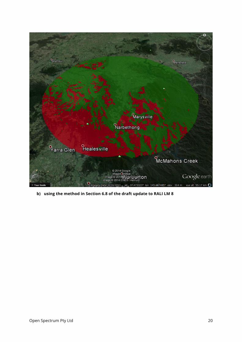
Open Spectrum Pty Ltd 20
b) using the method in Section 6.8 of the draft update to RALI LM 8
Open Spectrum Pty Ltd 21
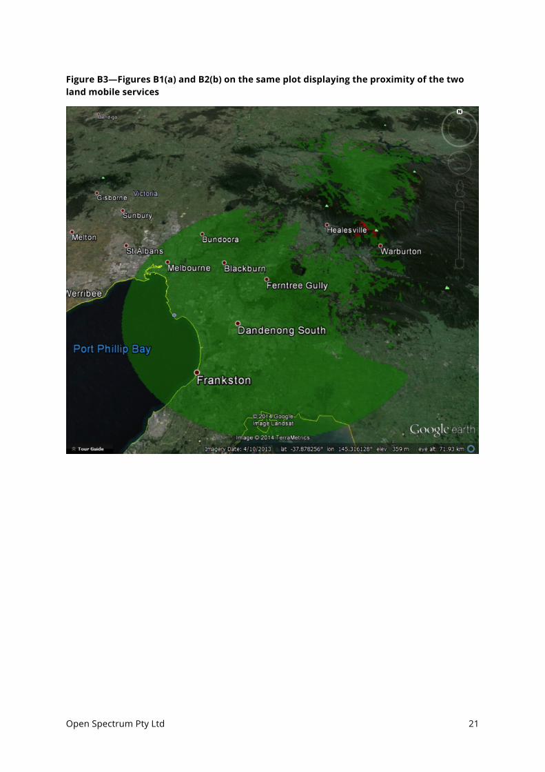
Figure B3—Figures B1(a) and B2(b) on the same plot displaying the proximity of the two land mobile services

Open Spectrum Pty Ltd 22
Annex C—Proposed clarifications in applicability of Tables C2 through C9
C2. Frequency-Distance Constraints for Single Frequency LMRS in the VHF Mid and High Bands The following frequency-distance constraints apply whenever:
• a single-frequency LMRS system (proposed or existing) requires frequency coordination;
• two-frequency systems are to be coordinated with one another, and one operates with reverse frequency sense to the other (i.e. the transmit frequency of one is the same as the receive frequency of the other); or
• a two-frequency system’s transmit frequency is close to a single frequency service receive frequency; or
• [proposed deletion: if the single frequency transmitter is LMRS (i.e. high power), then it already falls under the first dot point above] a two frequency system’s receive frequency is close to a single frequency service transmit frequency. For the VHF High Band, and subject to the above conditions, Table C2 applies only when both systems are LMRS (i.e. high power), otherwise Table C4 applies.
Table C2.1 - Frequency-Distance Constraints for 6.25 kHz Single Frequency LMRS in the VHF Mid and High Bands
Table C2.2 - Frequency-Distance Constraints for 12.5 kHz Single Frequency LMRS in the VHF Mid and High Bands
Table C2.3 - Frequency-Distance Constraints for 25 kHz Single Frequency LMRS in the VHF Mid and High Bands

Open Spectrum Pty Ltd 23
C3. Frequency-Distance Constraints for Single Frequency LMRS in the 400 MHz Band The following frequency-distance constraints apply whenever:
• a single-frequency LMRS system (proposed or existing) requires frequency coordination;
• two-frequency systems are to be coordinated with one another, and one operates with reverse frequency sense to the other (i.e. the transmit frequency of one is the same as the receive frequency of the other); or
• a two-frequency system’s transmit frequency is close to a single frequency service receive frequency.
Subject to the above conditions, Table C3 applies only when both systems are LMRS (i.e. high power), otherwise Table C4 applies.
Table C3.1 - Frequency-Distance Constraints for 6.25 kHz Single Frequency LMRS in the 400 MHz Band
Table C3.2 - Frequency-Distance Constraints for 12.5 kHz Single Frequency LMRS in the 400 MHz Band
Table C3.3 - Frequency-Distance Constraints for 25 kHz Single Frequency LMRS in the 400 MHz Band
Open Spectrum Pty Ltd 24
C4. Frequency-Distance Constraints for Single Frequency LPMRS in the VHF High Band and the 400 MHz Band The following frequency-distance constraints apply whenever:
• a single-frequency LPMRS (proposed or existing) requires frequency coordination;
• two-frequency LPMRS systems are to be coordinated with one another, and one operates with reverse frequency sense to the other (i.e. the transmit frequency of one is the same as the receive frequency of the other); or
• a two-frequency LPMRS system’s transmit frequency is close to a single frequency service receive frequency; or.
• a two-frequency system’s receive frequency is close to a single frequency service transmit frequency.
Subject to the above conditions, Table C4 applies only when at least one of the two systems is LPMRS (i.e. low power), otherwise Table C2 applies.
Furthermore, Tables C4.1 through C4.3 apply only when both of the two systems are LPMRS (i.e. low power), otherwise, Tables C4.4 through C4.6 apply for the VHF High Band, and Tables C4.7 through C4.9 apply for the 400 MHz Band.
Table C4.1 - Frequency-Distance Constraints for 6.25 kHz Single Frequency LPMRS in the VHF High Band and the 400 MHz Band
Table C4.2 - Frequency-Distance Constraints for 12.5 kHz Single Frequency LPMRS in the VHF High Band and the 400 MHz Band
Table C4.3 - Frequency-Distance Constraints for 25 kHz Single Frequency LPMRS in the VHF High Band and the 400 MHz Band
Subject to the above conditions, Tthe following frequency-distance constraints apply whenever high and low power single frequency systems in the VHF High Band are to be coordinated (proposed and existing).
Table C4.4 - Frequency-Distance Constraints for 6.25 kHz Single Frequency LMRS vs LPMRS in the VHF High Band.
Table C4.5 - Frequency-Distance Constraints for 12.5 kHz Single Frequency LMRS vs LPMRS in the VHF High Band.
Table C4.6 - Frequency-Distance Constraints for 25 kHz Single Frequency LMRS vs LPMRS in the VHF High Band.
TSubject to the above conditions, the following frequency-distance constraints apply whenever high and low power single frequency systems in the 400 MHz band are to be coordinated (proposed and existing).

Open Spectrum Pty Ltd 25
Table C4.7 - Frequency-Distance Constraints for 6.25 kHz Single Frequency LMRS vs LPMRS in the 400 MHz band.
Table C4.8 - Frequency-Distance Constraints for 12.5 kHz Single Frequency LMRS vs LPMRS in the 400 MHz band.
Table C4.9 - Frequency-Distance Constraints for 25 kHz Single Frequency LMRS vs LPMRS in the 400 MHz band.
C5. Frequency-Distance Constraints for Two Frequency LMRS in the VHF Mid and High Bands The following frequency-distance constraints apply whenever both systems to be coordinated (proposed and existing), use two frequency operation, and have the same frequency sense. For the VHF High Band, and subject to these conditions, Table C5 applies only when both systems are LMRS (i.e. high power).
Table C5.1 - Frequency-Distance Constraints for 6.25 kHz Two Frequency LMRS in the VHF High Bands
* This base-to-base distance separation is not required if the services are co-sited. This is because for the co-sited services the propagation path for the wanted and interfering signals is always the same and the receiver filtering will provide wanted-to-unwanted signal discrimination greater than the required protection ratio.
Table C5.2 - Frequency-Distance Constraints for 12.5 kHz Two Frequency LMRS in the VHF Mid and High Bands
Table C5.3 - Frequency-Distance Constraints for 25 kHz Two Frequency LMRS in the VHF Mid and High Bands
C6. Frequency-Distance Constraints for Two Frequency LMRS in the 400 MHz Band The following frequency-distance constraints apply whenever both systems to be coordinated (proposed and existing), use two frequency operation, and have the same frequency sense. Subject to these conditions, Table C5 applies only when both systems are LMRS (i.e. high power).
Table C6 - Frequency-Distance Constraints for Two Frequency LMRS in the 400 MHz Band
* This base-to-base distance separation is not required if the services are co-sited. This is because for the co-sited services the propagation path for the wanted and interfering signals is always the same and the receiver filtering will provide wanted-to-unwanted signal discrimination greater than the required protection ratio.
Open Spectrum Pty Ltd 26
C7. Frequency-Distance Constraints for Two Frequency LPMRS in the VHF High Band and the 400 MHz Band The following frequency-distance constraints apply whenever both systems to be coordinated (proposed and existing), use two frequency operation, and have the same frequency sense. Subject to these conditions, Table C7 applies only when both systems are LPMRS (i.e. low power).
Table C7 - Frequency-Distance Constraints for Two Frequency LPMRS in the VHF High Band and the 400 MHz Band
C8. Frequency-Distance Constraints for Two Frequency LMRS and LPMRS in the VHF High Band and the 400 MHz Band The following frequency-distance constraints apply whenever LMRS and LPMRS systems are to be coordinated (proposed and existing), use two frequency operation, and have the same frequency sense.
Table C8 - Frequency-Distance Constraints for Two Frequency LMRS vs LPMRS in the VHF High Band and the 400 MHz band
C9. Frequency-Distance Constraints for Trunked Services in the 800 MHz Trunking Band
Table C9 - Frequency-Distance Constraints for Trunked Services in the 800 MHz Trunking Band
Open Spectrum Pty Ltd 27
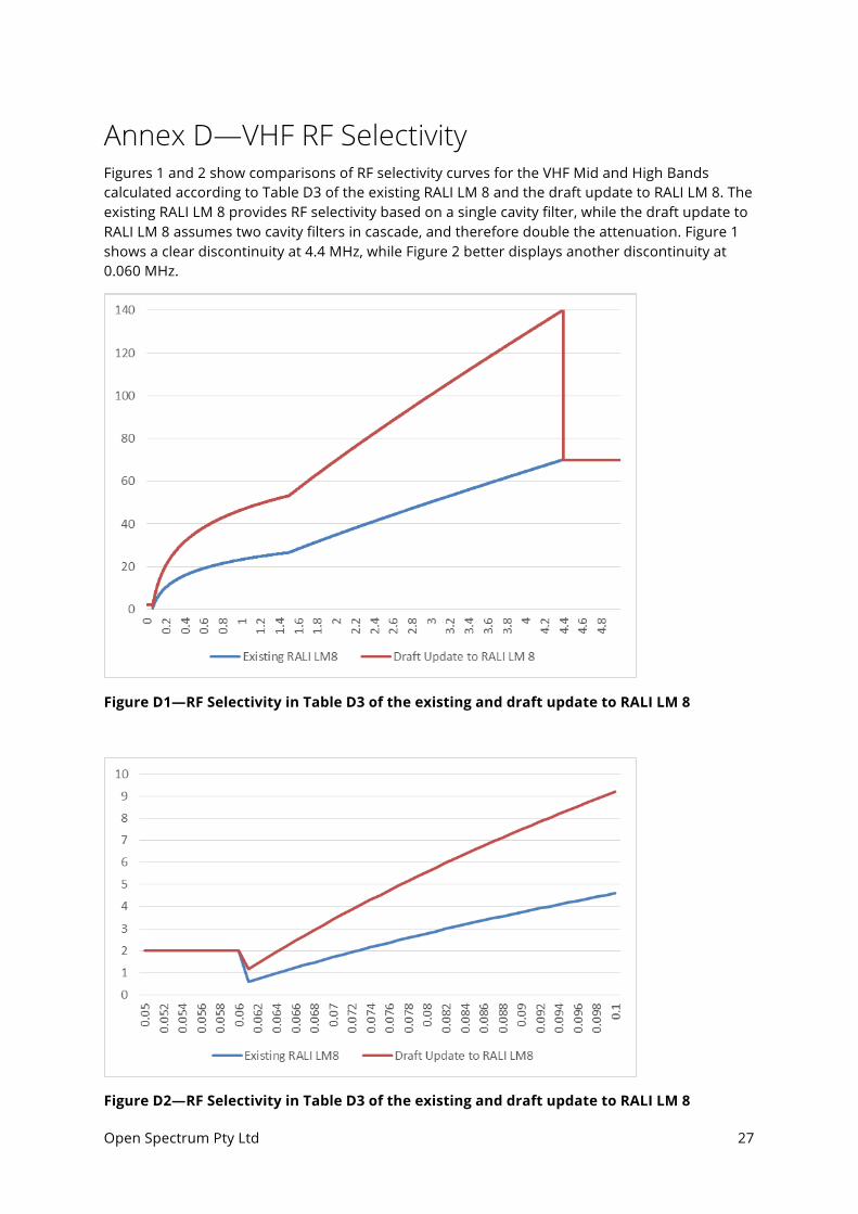
Annex D—VHF RF Selectivity Figures 1 and 2 show comparisons of RF selectivity curves for the VHF Mid and High Bands calculated according to Table D3 of the existing RALI LM 8 and the draft update to RALI LM 8. The existing RALI LM 8 provides RF selectivity based on a single cavity filter, while the draft update to RALI LM 8 assumes two cavity filters in cascade, and therefore double the attenuation. Figure 1 shows a clear discontinuity at 4.4 MHz, while Figure 2 better displays another discontinuity at 0.060 MHz.
Figure D1—RF Selectivity in Table D3 of the existing and draft update to RALI LM 8
Figure D2—RF Selectivity in Table D3 of the existing and draft update to RALI LM 8
Open Spectrum Pty Ltd 28
Annex E—Addition of RF Selectivity to FDR SPP 08/14, pages 20 through 23, specifies the methodology used to calculate the frequency-distance constraints in the draft update to RALI LM 8. The distance in these constraints is the minimum distance between interfering BS and victim receiver such that the interference level at the latter does not exceed the maximum acceptable interference level, noting some exceptions for two-frequency systems. Equation 2 is:
Pr = EIRP + Gr – Lpath – FDR – Selrx
where FDR is frequency dependent rejection and Selrx is the base station front-end response achieved by the RF selectivity of the receiver (0 dB for two-frequency systems).
There are two issues with the subtraction of Selrx in Equation 2.
a) Conceptually, arithmetic addition of RF selectivity to FDR, of which receiver frequency response is an input, is incorrect.
b) Insertion loss of the cavity filters (e.g. 2 dB in the VHF Mid and High Bands and 5 dB in the 400 MHz Band) cannot be used to reduce the interfering signal level, since insertion loss also reduces the wanted signal level.
This Annex explains issue (a) above. For the following explanation, Open Spectrum has assumed that:
• the emission spectrum mask is always –∞ dB beyond 100 kHz4 • Selrx is RF Selectivity in Table D3 of RALI LM 8 for the VHF Mid and High Bands, as
proposed to be revised by Open Spectrum in Section 5.1 of this submission, and minus insertion loss (i.e. 2 dB)
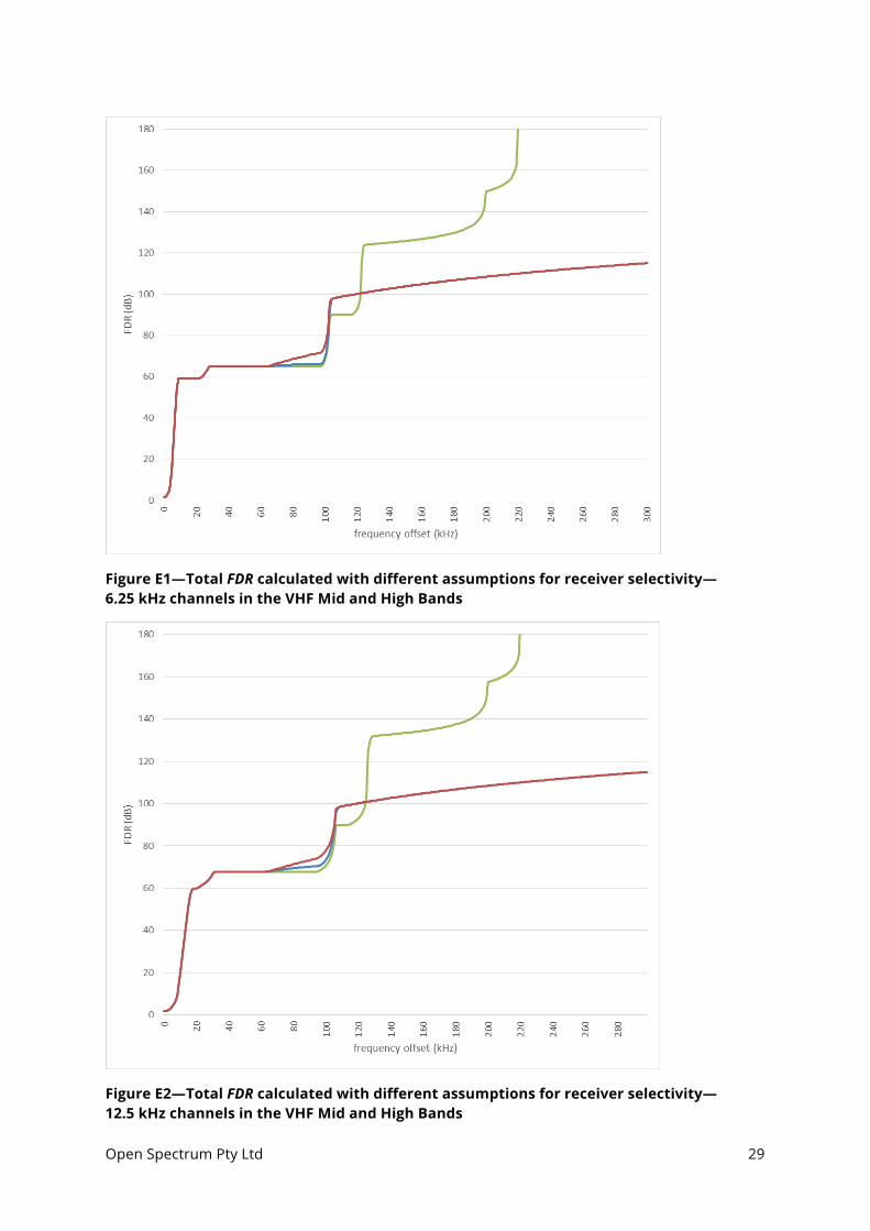
Figures E1, E2 and E3 each show three curves for total off-channel rejection:
1. FDR only—receiver selectivity is –∞ dB beyond 120 kHz—green curve 2. FDR incorporates Selrx—receiver selectivity is –90 dB beyond 120 kHz; Selrx is then added
to receiver selectivity prior to calculation of FDR—blue curve (see also Figure E4) 3. FDR + Selrx—FDR is calculated for receiver selectivity equal to –90 dB beyond 120 kHz; Selrx
is then added to FDR as in Equation 2 of SPP 08/14—red curve
In Figures E1, E2 and E3, the discrepancy resulting from the arithmetic addition of Selrx to FDR as in Equation 2 of SPP 08/14 is displayed in the difference between the blue and red curves. This shows that for the VHF Mid and High Bands, the addition of RF selectivity as in Equation 2 of SPP 08/14 results in some discrepancy, which in this case is limited to frequency offsets between 60 kHz and 100 kHz.
For the 400 MHz band, there is only additional RF selectivity for frequency offsets above 100 kHz. Since the receiver selectivity is constant above 100 kHz, the addition of RF selectivity as in Equation 2 of SPP 08/14 will not result in any discrepancy for the 400 MHz band.
4 SPP 08/14, page 23 states: “Beyond the edges of the masks specified by the user: rather than a roll-off, the response is assumed to drop to zero (i.e. –∞ dB)”.
Open Spectrum Pty Ltd 29
Figure E1—Total FDR calculated with different assumptions for receiver selectivity—6.25 kHz channels in the VHF Mid and High Bands
Figure E2—Total FDR calculated with different assumptions for receiver selectivity—12.5 kHz channels in the VHF Mid and High Bands

Open Spectrum Pty Ltd 30
Figure E3—Total FDR calculated with different assumptions for receiver selectivity—25 kHz channels in the VHF Mid and High Bands
Figure E4—Example of addition of Selrx (without insertion loss) to receiver selectivity prior to calculation of FDR
Open Spectrum Pty Ltd 31
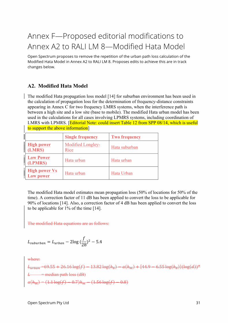
Annex F—Proposed editorial modifications to Annex A2 to RALI LM 8—Modified Hata Model Open Spectrum proposes to remove the repetition of the urban path loss calculation of the Modified Hata Model in Annex A2 to RALI LM 8. Proposes edits to achieve this are in track changes below.
A2. Modified Hata Model
The modified Hata propagation loss model [14] for suburban environment has been used in the calculation of propagation loss for the determination of frequency-distance constraints appearing in Annex C for two frequency LMRS systems, when the interference path is between a high site and a low site (base to mobile). The modified Hata urban model has been used in the calculations for all cases involving LPMRS systems, including coordination of LMRS with LPMRS. [Editorial Note: could insert Table 12 from SPP 08/14, which is useful to support the above information]
Single frequency Two frequency
High power (LMRS)
Modified Longley-Rice Hata suburban
Low Power (LPMRS) Hata urban Hata urban
High power Vs Low power Hata urban Hata Urban
The modified Hata model estimates mean propagation loss (50% of locations for 50% of the time). A correction factor of 11 dB has been applied to convert the loss to be applicable for 90% of locations [14]. Also, a correction factor of 4 dB has been applied to convert the loss to be applicable for 1% of the time [14].
The modified Hata equations are as follows:
𝐿!"#"!"#$ = 𝐿!"#$% − 2log (𝑓28)
! − 5.4
where:
𝐿!"#$% =69.55+ 26.16 log 𝑓 − 13.82 log ℎ! − 𝑎 ℎ! + 44.9− 6.55 log ℎ! (log 𝑑 )!
𝐿 = median path loss (dB)
𝑎 ℎ! = 1.1 log 𝑓 − 0.7 ℎ! − 1.56 log 𝑓 − 0.8
Open Spectrum Pty Ltd 32
𝛼 = 𝛼 = 1 𝑓𝑜𝑟 𝑑 ≤ 20𝑘𝑚𝛼 = 1+ 0.14+ 0.000187𝑓 + 0.00107ℎ! (log
!!")!.! 𝑓𝑜𝑟 20𝑘𝑚 < 𝑑
d = distance (km) f = frequency (MHz)
ℎ! , ℎ! = base and mobile antenna heights respectively (m)
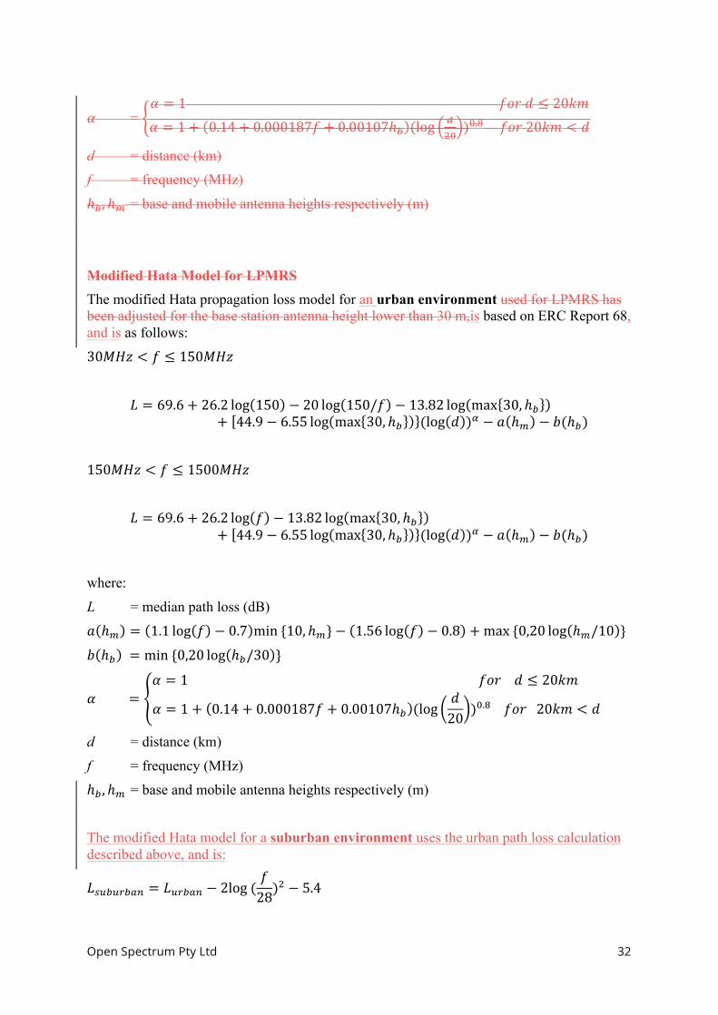
Modified Hata Model for LPMRS The modified Hata propagation loss model for an urban environment used for LPMRS has been adjusted for the base station antenna height lower than 30 m,is based on ERC Report 68, and is as follows:
30𝑀𝐻𝑧 < 𝑓 ≤ 150𝑀𝐻𝑧
𝐿 = 69.6+ 26.2 log 150 − 20 log 150/𝑓 − 13.82 log max 30, ℎ!+ 44.9− 6.55 log max 30, ℎ! (log 𝑑 )! − 𝑎 ℎ! − 𝑏(ℎ!)
150𝑀𝐻𝑧 < 𝑓 ≤ 1500𝑀𝐻𝑧
𝐿 = 69.6+ 26.2 log 𝑓 − 13.82 log max 30, ℎ!+ 44.9− 6.55 log max 30, ℎ! (log 𝑑 )! − 𝑎 ℎ! − 𝑏(ℎ!)
where:
L = median path loss (dB)
𝑎 ℎ! = 1.1 log 𝑓 − 0.7 min {10, ℎ!}− 1.56 log 𝑓 − 0.8 +max {0,20 log ℎ!/10 }
𝑏 ℎ! = min {0,20 log ℎ!/30 }
𝛼 =𝛼 = 1 𝑓𝑜𝑟 𝑑 ≤ 20𝑘𝑚
𝛼 = 1+ 0.14+ 0.000187𝑓 + 0.00107ℎ! (log𝑑20 )!.! 𝑓𝑜𝑟 20𝑘𝑚 < 𝑑
d = distance (km)
f = frequency (MHz)
ℎ! , ℎ! = base and mobile antenna heights respectively (m)
The modified Hata model for a suburban environment uses the urban path loss calculation described above, and is:
𝐿!"#"$#%& = 𝐿!"#$% − 2log (𝑓28)
! − 5.4
Open Spectrum Pty Ltd 33
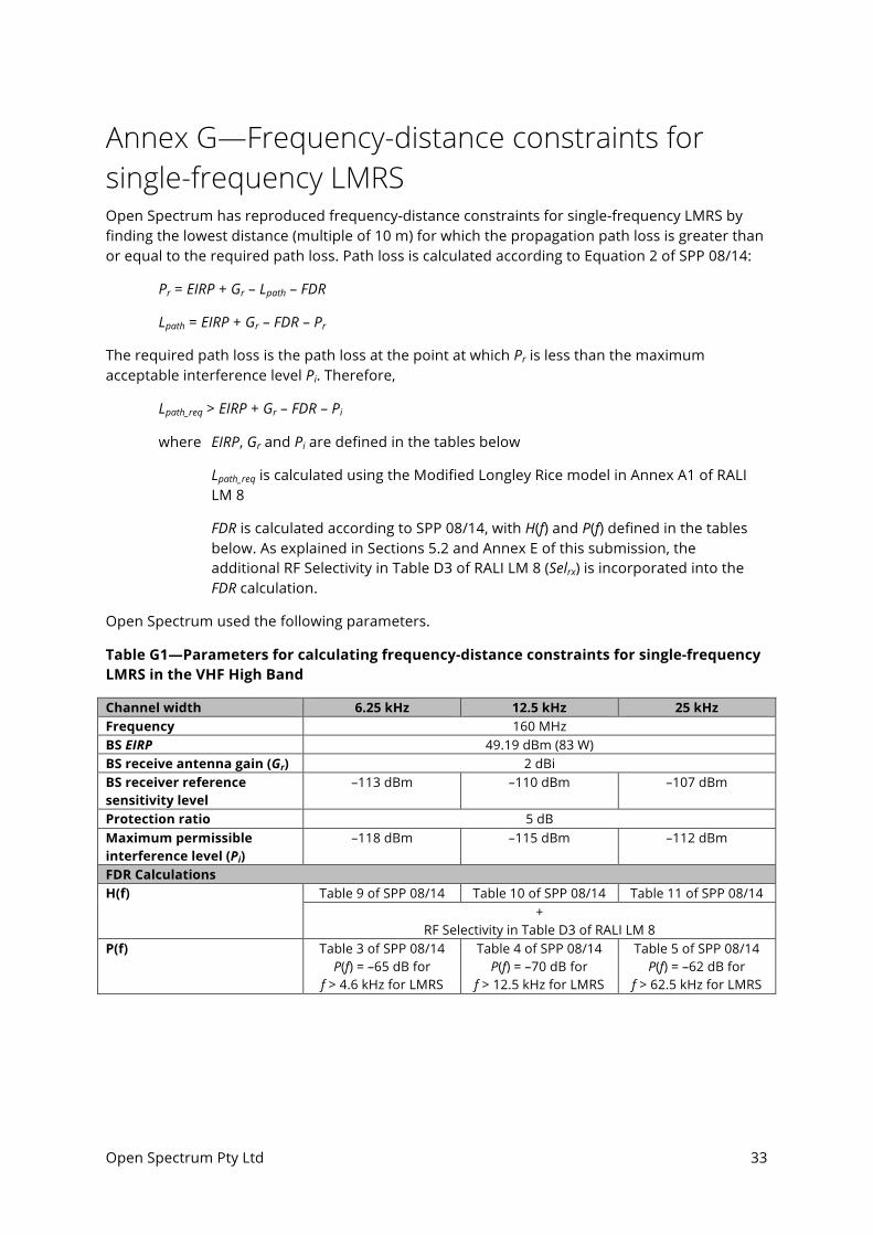
Annex G—Frequency-distance constraints for single-frequency LMRS Open Spectrum has reproduced frequency-distance constraints for single-frequency LMRS by finding the lowest distance (multiple of 10 m) for which the propagation path loss is greater than or equal to the required path loss. Path loss is calculated according to Equation 2 of SPP 08/14:
Pr = EIRP + Gr – Lpath – FDR
Lpath = EIRP + Gr – FDR – Pr
The required path loss is the path loss at the point at which Pr is less than the maximum acceptable interference level Pi. Therefore,
Lpath_req > EIRP + Gr – FDR – Pi
where EIRP, Gr and Pi are defined in the tables below
Lpath_req is calculated using the Modified Longley Rice model in Annex A1 of RALI LM 8
FDR is calculated according to SPP 08/14, with H(f) and P(f) defined in the tables below. As explained in Sections 5.2 and Annex E of this submission, the additional RF Selectivity in Table D3 of RALI LM 8 (Selrx) is incorporated into the FDR calculation.
Open Spectrum used the following parameters.
Table G1—Parameters for calculating frequency-distance constraints for single-frequency LMRS in the VHF High Band
Channel width 6.25 kHz 12.5 kHz 25 kHz Frequency 160 MHz BS EIRP 49.19 dBm (83 W) BS receive antenna gain (Gr) 2 dBi BS receiver reference sensitivity level
–113 dBm –110 dBm –107 dBm
Protection ratio 5 dB Maximum permissible interference level (Pi)
–118 dBm –115 dBm –112 dBm
FDR Calculations H(f) Table 9 of SPP 08/14 Table 10 of SPP 08/14 Table 11 of SPP 08/14
+ RF Selectivity in Table D3 of RALI LM 8
P(f) Table 3 of SPP 08/14 P(f) = –65 dB for
f > 4.6 kHz for LMRS
Table 4 of SPP 08/14 P(f) = –70 dB for
f > 12.5 kHz for LMRS
Table 5 of SPP 08/14 P(f) = –62 dB for
f > 62.5 kHz for LMRS
Open Spectrum Pty Ltd 34
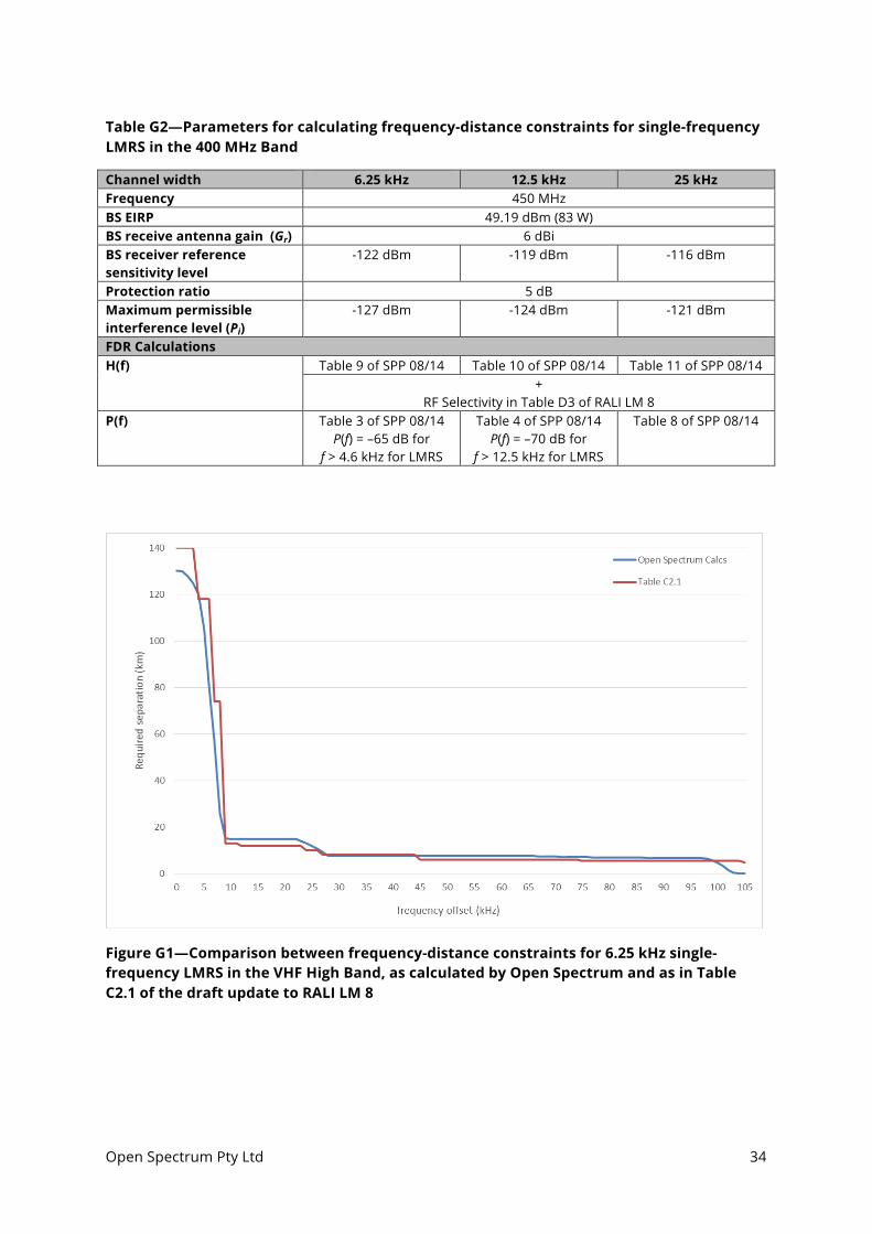
Table G2—Parameters for calculating frequency-distance constraints for single-frequency LMRS in the 400 MHz Band
Channel width 6.25 kHz 12.5 kHz 25 kHz Frequency 450 MHz BS EIRP 49.19 dBm (83 W) BS receive antenna gain (Gr) 6 dBi BS receiver reference sensitivity level
-122 dBm -119 dBm -116 dBm
Protection ratio 5 dB Maximum permissible interference level (Pi)
-127 dBm -124 dBm -121 dBm
FDR Calculations H(f) Table 9 of SPP 08/14 Table 10 of SPP 08/14 Table 11 of SPP 08/14
+ RF Selectivity in Table D3 of RALI LM 8
P(f) Table 3 of SPP 08/14 P(f) = –65 dB for
f > 4.6 kHz for LMRS
Table 4 of SPP 08/14 P(f) = –70 dB for
f > 12.5 kHz for LMRS
Table 8 of SPP 08/14
Figure G1—Comparison between frequency-distance constraints for 6.25 kHz single-frequency LMRS in the VHF High Band, as calculated by Open Spectrum and as in Table C2.1 of the draft update to RALI LM 8
Open Spectrum Pty Ltd 35
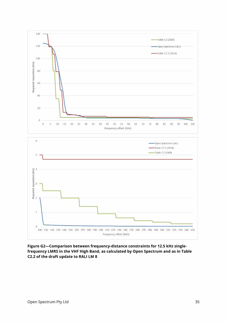
Figure G2—Comparison between frequency-distance constraints for 12.5 kHz single-frequency LMRS in the VHF High Band, as calculated by Open Spectrum and as in Table C2.2 of the draft update to RALI LM 8
Open Spectrum Pty Ltd 36
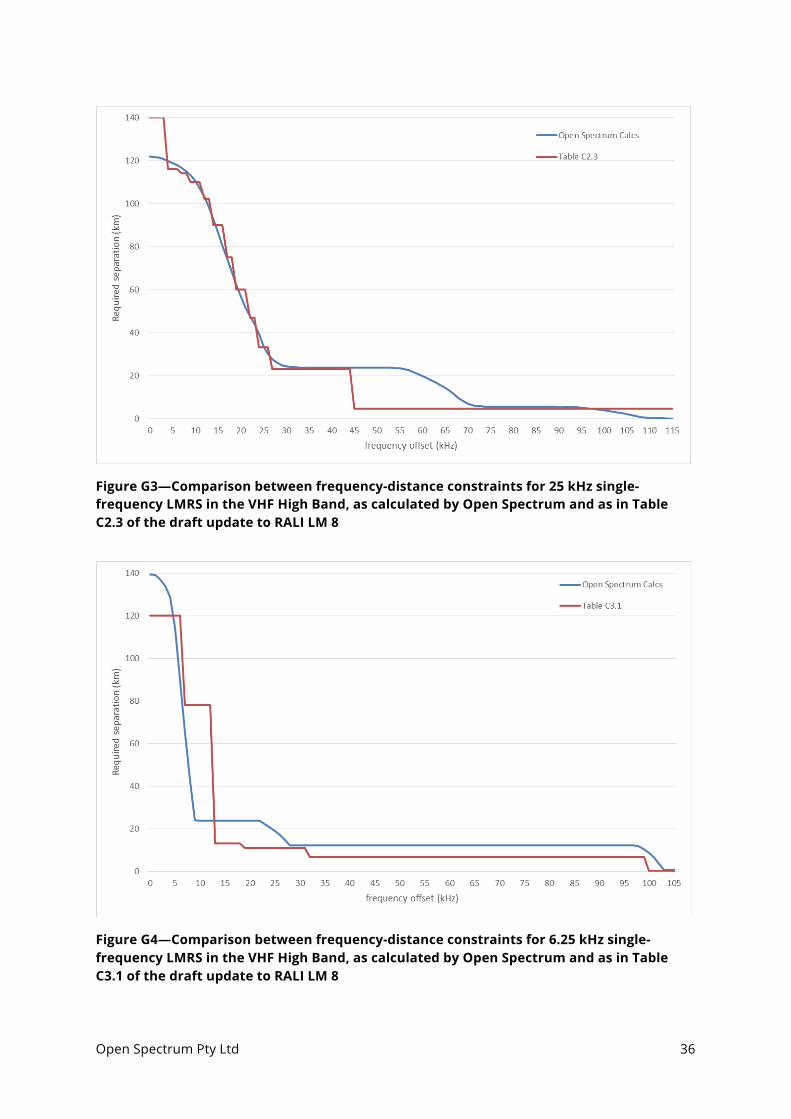
Figure G3—Comparison between frequency-distance constraints for 25 kHz single-frequency LMRS in the VHF High Band, as calculated by Open Spectrum and as in Table C2.3 of the draft update to RALI LM 8
Figure G4—Comparison between frequency-distance constraints for 6.25 kHz single-frequency LMRS in the VHF High Band, as calculated by Open Spectrum and as in Table C3.1 of the draft update to RALI LM 8
Open Spectrum Pty Ltd 37
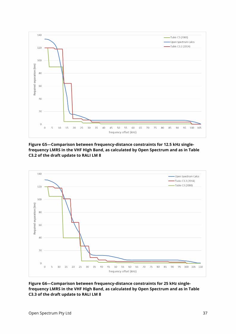
Figure G5—Comparison between frequency-distance constraints for 12.5 kHz single-frequency LMRS in the VHF High Band, as calculated by Open Spectrum and as in Table C3.2 of the draft update to RALI LM 8
Figure G6—Comparison between frequency-distance constraints for 25 kHz single-frequency LMRS in the VHF High Band, as calculated by Open Spectrum and as in Table C3.3 of the draft update to RALI LM 8