IEEE TRANSACTIONS ON VEHICULAR TECHNOLOGY...
13
IEEE TRANSACTIONS ON VEHICULAR TECHNOLOGY 1 Efficient Message Composition and Coding for Cooperative Vehicular Safety Applications C. L. Robinson, Student Member, IEEE, D. Caveney, Member, IEEE, L. Caminiti, G. Baliga, K. Laberteaux Member, IEEE, and P. R. Kumar, Fellow, IEEE. (Invited Paper) Abstract—Wireless inter-vehicular communication will en- able a broad range of applications in the future. However, multiple vehicles, multiple diverse applications, multiple vehicle manufacturers and the mobile vehicular environment raise several issues related to utilizing the wireless medium effectively. In this paper we present a method for efficiently communi- cating vehicle data amongst neighbouring vehicles, primarily for safety applications. The “Message Dispatcher” (MD) coordinates communication between applications and the wireless channel at the application level. It addresses tech- nical implementation issues, business deployment consider- ations and issues of extensibility and system architecture. The Message Dispatcher concept has become an integral part of the Society of Automotive Engineers safety message standardization effort. We shall describe the Message Dispatcher and present results illustrating its utility. We also describe a deployment in several vehicles at the Toyota Technical Center in Ann Arbor, MI. Then, using data collected from the vehicles, we investigate a Predictive Coding method for data transmission using the Message Dispatcher. We show that this scheme can reduce wireless channel utilization and bandwidth re- quirements by over 80% compared to regular transmission methods. Several insights for future wireless channel usage optimization are provided. I. I T O enable proliferation of wireless communication between vehicles we must consider methods to more efficiently use the scarce and shared wireless medium. Competition for access to the wireless channel will only increase as more vehicles become equipped with the required technology. New and evolving ap- plications will also drive this demand and generate new data and transmission requirements. This paper describes a method for efficiently creating message pack- ets for wireless vehicle-to-vehicle (V2V) and vehicle-to- infrastructure (V2I) communications. It addresses several implementation issues, restrictions and objectives, and describes some preliminary solutions to these problems. This work has been supported by a Toyota research contract at the University of Illinois at Urbana Champaign. C. L. Robinson is with the Department of Industrial and Enterprise Systems Engineering and P.R. Kumar is with the Electrical and Com- puter Engineering Department at the University of Illinois at Urbana Champaign, IL, 61801 USA e-mail: clrobnsn—[email protected]. D. Caveney. L. Caminiti and K. Laberteaux are at the Toyota Technical Center in Ann Arbor, MI. email lorenzo.caminiti—derek.caveney—[email protected]. G. Baliga is with Google Inc. [email protected]. The general approach is to reduce channel load by exploiting similarities in transmitted data, as well as efficient inclusion of individual data elements. We focus predominantly on intervehicular safety ap- plications. In this domain, Dedicated Short Range Com- munications (DSRC) [8]–[10] is the leading wireless tech- nology under consideration [1]. Significant progress has been made in standardizing the lower layer protocols for DSRC [8], [10]. Safety applications and related tech- nologies are being examined by industry/government consortiums, such as the Crash Avoidance Metrics Part- nership (CAMP) [17], [18], the Car2Car Communications Consortium [19] and the Advanced Safety Vehicle (ASV) Project [20]. The task of specifying safety message composition and creation, the area of this paper, belongs to the Society of Automotive Engineers (SAE). Specifically, the draft stan- dard SAE J2735, Dedicated Short Range Communication (DSRC) Message Set Dictionary [11] defines several static message structures, as well as a method to efficiently and dynamically create messages. This flexible method was contributed to SAE by the authors of this paper in the form of the Message Dispatcher which is fully described, and extended upon, below. As we shall describe in Section II, the automotive ap- plications that appear to have the greatest safety poten- tial rely heavily on single-hop broadcast communication with nearby vehicles and infrastructure. Further, it ap- pears likely that implementation of vehicular safety ap- plications will be executed quasi-autonomously by each manufacturer. The eventual vehicular wireless commu- nication environment is expected to have devices from various manufacturers implementing distinct (although potentially cooperative) applications. Moreover, many vehicles are likely to run multiple safety applications concurrently (e.g., an emergency brake light application, a lane change warning application, an intersection colli- sion warning application, etc.). Each application is likely to have different, although overlapping, data element requirements, i.e., many safety applications may require the vehicle speed, vehicle location, current turning ra- dius, etc. This has the potential to generate packets with redundant data. For example, it is not efficient for several applications within a single vehicle to separately (and redundantly) send the vehicles current speed. Also, information that changes slowly or infrequently (e.g.,
Transcript of IEEE TRANSACTIONS ON VEHICULAR TECHNOLOGY...

IEEE TRANSACTIONS ON VEHICULAR TECHNOLOGY 1
Efficient Message Composition and Coding forCooperative Vehicular Safety Applications
C. L. Robinson, Student Member, IEEE, D. Caveney, Member, IEEE, L. Caminiti,G. Baliga, K. Laberteaux Member, IEEE, and P. R. Kumar, Fellow, IEEE.
(Invited Paper)
Abstract—Wireless inter-vehicular communication will en-able a broad range of applications in the future. However,multiple vehicles, multiple diverse applications, multiplevehicle manufacturers and the mobile vehicular environmentraise several issues related to utilizing the wireless mediumeffectively.In this paper we present a method for efficiently communi-
cating vehicle data amongst neighbouring vehicles, primarilyfor safety applications. The “Message Dispatcher” (MD)coordinates communication between applications and thewireless channel at the application level. It addresses tech-nical implementation issues, business deployment consider-ations and issues of extensibility and system architecture.The Message Dispatcher concept has become an integralpart of the Society of Automotive Engineers safety messagestandardization effort.We shall describe the Message Dispatcher and present
results illustrating its utility. We also describe a deploymentin several vehicles at the Toyota Technical Center in AnnArbor, MI. Then, using data collected from the vehicles, weinvestigate a Predictive Coding method for data transmissionusing the Message Dispatcher. We show that this schemecan reduce wireless channel utilization and bandwidth re-quirements by over 80% compared to regular transmissionmethods. Several insights for future wireless channel usageoptimization are provided.
I. I
TO enable proliferation of wireless communicationbetween vehicles we must consider methods to
more efficiently use the scarce and shared wirelessmedium. Competition for access to the wireless channelwill only increase as more vehicles become equippedwith the required technology. New and evolving ap-plications will also drive this demand and generatenew data and transmission requirements. This paperdescribes a method for efficiently creating message pack-ets for wireless vehicle-to-vehicle (V2V) and vehicle-to-infrastructure (V2I) communications. It addresses severalimplementation issues, restrictions and objectives, anddescribes some preliminary solutions to these problems.
This work has been supported by a Toyota research contract at theUniversity of Illinois at Urbana Champaign.C. L. Robinson is with the Department of Industrial and EnterpriseSystems Engineering and P.R. Kumar is with the Electrical and Com-puter Engineering Department at the University of Illinois at UrbanaChampaign, IL, 61801 USA e-mail: clrobnsn—[email protected]. Caveney. L. Caminiti and K. Laberteaux are atthe Toyota Technical Center in Ann Arbor, MI. emaillorenzo.caminiti—derek.caveney—[email protected]. Baliga is with Google Inc. [email protected].
The general approach is to reduce channel load byexploiting similarities in transmitted data, as well asefficient inclusion of individual data elements.We focus predominantly on intervehicular safety ap-plications. In this domain, Dedicated Short Range Com-munications (DSRC) [8]–[10] is the leading wireless tech-nology under consideration [1]. Significant progress hasbeen made in standardizing the lower layer protocolsfor DSRC [8], [10]. Safety applications and related tech-nologies are being examined by industry/governmentconsortiums, such as the Crash Avoidance Metrics Part-nership (CAMP) [17], [18], the Car2Car CommunicationsConsortium [19] and the Advanced Safety Vehicle (ASV)Project [20].The task of specifying safety message composition andcreation, the area of this paper, belongs to the Society ofAutomotive Engineers (SAE). Specifically, the draft stan-dard SAE J2735, Dedicated Short Range Communication(DSRC) Message Set Dictionary [11] defines several staticmessage structures, as well as a method to efficiently anddynamically create messages. This flexible method wascontributed to SAE by the authors of this paper in theform of the Message Dispatcher which is fully described,and extended upon, below.As we shall describe in Section II, the automotive ap-plications that appear to have the greatest safety poten-tial rely heavily on single-hop broadcast communicationwith nearby vehicles and infrastructure. Further, it ap-pears likely that implementation of vehicular safety ap-plications will be executed quasi-autonomously by eachmanufacturer. The eventual vehicular wireless commu-nication environment is expected to have devices fromvarious manufacturers implementing distinct (althoughpotentially cooperative) applications. Moreover, manyvehicles are likely to run multiple safety applicationsconcurrently (e.g., an emergency brake light application,a lane change warning application, an intersection colli-sion warning application, etc.). Each application is likelyto have different, although overlapping, data elementrequirements, i.e., many safety applications may requirethe vehicle speed, vehicle location, current turning ra-dius, etc. This has the potential to generate packetswith redundant data. For example, it is not efficient forseveral applications within a single vehicle to separately(and redundantly) send the vehicles current speed. Also,information that changes slowly or infrequently (e.g.,

IEEE TRANSACTIONS ON VEHICULAR TECHNOLOGY 2
windscreen wiper status) need not be sent frequently1.The Message Dispatcher (MD) addresses this Data Ele-ment coordination issue. Briefly, the MD sits between theapplications and the lower-layer protocols, to coordinatethe data requirements of each application. Its goal is toreduce the redundancy of the broadcast data. We shallfocus on two approaches to achieve this in this paper.First, duplicate data elements from various applica-tions are combined into a single message and only sentonce. Further efficiencies can be obtained by coordinat-ing transmissions so as to meet minimum transmissionfrequency or latency requirements. We present someprimitive results showing that the MD approach greatlyreduces the expected channel usage.Second, using ideas from Predictive Coding [21], onecan use a model for state estimation, and an updatescheme which transmits data elements only when themodel estimate is inaccurate. We also examine the pre-dictive coding method whereby small state ‘corrections’requiring fewer bits are transmitted, as compared toa full data element. We shall demonstrate that thesemethods have the desirable effect of reducing channelutilization, thereby mitigating channel congestion andthus data loss and delay. We shall quantify the reductionin this paper.The Message Dispatcher has been successfully im-plemented in a testbed for cooperative vehicle safetydemonstrations at the Toyota Technical Center (TTC),confirming its feasibility and flexibility. Using actual ve-hicle data collected from the testbed for multiple driversdriving multiple routes on public roads, we show thatusing predictive coding can reduce channel usage byover 80%.The remainder of this paper is organized as follows.In Section II, the unique characteristics of the SafetyVehicular Ad-hoc NETworks (SVANET) are described.This includes a description of some of the the currenttrends in safety applications and their Data Elementrequirements. The section also identifies several idealfeatures of a SVANET system. Section III outlines theMessage Dispatcher architecture. Section IV describesthe MD implementation and vehicle testbed at TTC. InSection VI we describe the predictive coding approachand based on the testbed data we analyze the reductionin channel load. Section VII evaluates the MD againstthe goals outlined in Section II. Conclusions as well aspotential extensions are made in Section VIII.Some of this work has previously been presentedin [16]. The extensions in this paper are sections relatedto the predictive coding, as well as the collection andanalysis of the testbed data sets.
II. P F
This section describes cooperative vehicular safetyapplications and their communication requirements. It
1This statement ignores a potential requirement that new neighboursof a vehicle be promptly updated with the vehicles current state. Thiscan be addressed in our proposal, as described in Section VI-C.
further provides other attractive features of a data ex-change system for vehicular safety.
A. Vehicular Safety Applications and Data Requirements
Significant efforts, involving the vehicle industry andgovernment agencies mentioned in Section I, have beenmade to identify which communication-enabled vehicu-lar safety applications will provide the greatest benefits.The deliberations by the US National Highway TrafficSafety Administration (NHTSA), the US Department ofTransportation (USDOT), and the Vehicle Safety Com-munications Consortium (VSCC) of CAMP have iden-tified eight such applications [1], [2] shown in Table Ialong with their proposed communication requirements2.We highlight that these requirements have only beenproposed. There has, to the authors’ knowledge, been nothorough investigation or deployment of these systemson which these requirements are based. This highlightsthe requirement that any communication protocol besufficiently flexible to enable changing requirements. Thesalient features of the table are that the communicationfrequency ranges from 1-50 Hz, the size of the packetranges 200-500 bytes, and the maximum communicationrange spans from 50-300 meters. Further, some DataElements (e.g., Position and Heading) are needed bymultiple applications.Responding to these identified applications, theSAE [11] defines over seventy vehicle Data Elements(e.g., latitude and longitude position, heading, accelera-tion (with varying precision: 4bit, 8bit, 16 bit), headlightstatus and brake status). Of these Data Elements, thirtyof the most frequently used elements are selected as thebasis of a “common message set”. The common messageset is intended to provide a standardized set of messageswhich vehicles could use to communicate. The messageswere all of fixed size, structure and contents. However,since very few of the intended applications have actuallybeen implemented or fully developed, the exact usagecharacteristics of the safety messages were in flux at thetime they were being defined and standardized. Thismade the process difficult, as these choices are likely tobe refined over time. It is however clear from Table Ithat several Data Elements will be useful to multiple ap-plications, although perhaps at different frequencies anddistances. It is further quite likely that some of the SAEsData Elements, such as AirBagCount, AirTemperature, andWiperRate, will be used far-less frequently. This leads tothe conclusion that a message with fixed contents willeither be very large, or not be able to meet all applicationrequirements. This observation motivated the work inthis paper.
B. Broadcast Characteristics
As illustrated in Table I, safety messages tend to belocally broadcast with a maximum transmission range
2Similar deliberations are underway in Europe and Asia, with sim-ilar results.
IEEE TRANSACTIONS ON VEHICULAR TECHNOLOGY 3
Application Comm. type Freq. Latency Data Transmitted Range
Traffic Signal ViolationI2V 10 Hz 100msec Signal Status, Timing, Surface 250m
One-way, P2M Heading, Light Posn.,Weather,
Curve Speed WarningI2V 1 Hz 1000msec Curve Location, Curvature, 200m
One-way , P2M Speed Limit, Bank, Surface
Emergency Brake LightsVehicle to Vehicle 10 Hz 100msec Position, Deceleration 200mTwo-way, P2M Heading, Velocity,
Pre-Crash SensingVehicle to Vehicle 50 Hz 20msec Vehicle Type, Yaw Rate, 50mTwo-way, P2P Position, Heading, Accel.
Collision WarningVehicle to Vehicle 10 Hz 100msec Vehicle Type, Position, Heading 150mOne-way, P2M Velocity, Acceleration, Yaw Rate
Left Turn AssistI2V and V2I 10 Hz 100msec Signal Status, Timing, Posn. 300mOne-way, P2M Direction, Road Geom., Vel. Heading
Lane Change WarningVehicle to Vehicle 10 Hz 100msec Position, Heading, Velocity 150mOne-way, P2M. Accel., Turn Signal Status,
Stop Sign AssistI2V and V2I 10 Hz 100msec Position, Velocity 300mOne-way Heading, Warning.
TABLE IE - NHTSA VSCC [2]. N 1-50H 50-300 . P2P ‘P--P’, P2M ‘P--M’, I2V
‘I--V’ V2I ‘V--I’.
.
of 300 meters; messages sent by a vehicle will containData Elements useful to multiple vehicles in the nearbyvicinity. As DSRC radios are required to communicateat least 300 meters, we assume that safety messagesbroadcast their messages in a single hop3.As a result of the highly dynamic vehicular environ-ment, it is likely that the nearby neighbors of a vehiclewill change frequently. It is likely unnecessary, and moredifficult, to maintain an updated topology of 1-3 hopneighbors. Again, 1-hop broadcasts seem appropriate.Further, coordinating transmission between vehicles willbe difficult. Packet interference and loss seem likely. Weapproach this issue by attempting to reduce channel loadand use the channel infrequently.
C. Desirable Architectural Features
In addition to simply providing information useful forthe defined applications, there are several goals which anarchitecture should satisfy. These goals are driven bothfrom a technical standpoint, as well as a business per-spective, in that real world deployment and proliferationconsiderations need to be made.Future Proof: Vehicles will broadcast data that islikely valuable for multiple surrounding vehicles withmultiple safety applications. However, creating and test-ing these safety applications is an ongoing effort. Assuch, a scheme must be backward compatible as wellas future proof to newly-defined, evolving, or upgradedapplications.Flexibility: It seems likely that in the heterogeneousmarketplace for vehicles, different vehicles will be run-ning different subsets of safety applications. A schemeshould be sufficiently flexible to account for this, as wellas the other requirements mentioned in this section.
3Extensions, such as dynamic power control [12] and geographicalflooding [13], are also possible in Safety VANET. The Message Dis-patcher concept readily extends to these situations.
Extensible: It is conceivable that not all safety ap-plications will be universally standardized. Hence, amechanism for adding support for non-standardizedData Elements (e.g., proprietary to one or more man-ufacturers) would be desirable. This would ensure thatapplications would not be restricted by constraints onthe information they are able to communicate.Unified Interface: From an implementation perspec-tive it is attractive to construct an architecture wherepolicy and self-policing between various applications,within a single vehicle, can be managed in a singleentity. Further, authentication and other security primi-tives would ideally be managed collectively across safetyapplications.Layered Architecture: By providing a layered architec-ture that abstracts the message sending interface fromthe application designer, a separation of concerns forthe application designer is achieved. This enables easier,faster and more modular development.Low Bandwidth usage: The available bandwidth is afinite resource and should be conserved wherever pos-sible. Real-world testing by the VSCC [2] demonstratesthat the channel capacity is an issue that will need tobe addressed for large-scale deployment and in heavytraffic environments.Information Rate: Some Data Elements, such as head-light status, change infrequently. Thus, a solution shoulddistinguish these properties and transmit informationonly when it is appropriate.Recognize vehicle capabilities: Not all vehicles willbe able (or willing) to measure and transmit certainpieces of information. This should be reflected in themessage construction.Enable Product Differentiation: Vehicle manufactur-ers desire the ability to provide unique applications andservices to their customers. The functionality of theseservices should not be limited to the applications thatare currently deployed or enabled by other vendors.
IEEE TRANSACTIONS ON VEHICULAR TECHNOLOGY 4
MessageDispatcher
Vehicle / OEM Specific Standardized
SourceData
Application 2
Application 3
Application 1
Brake Status
Position, SpeedBrake Status
Tire Brand
Position,Acceleration
Position, Speed,
Acceleration,
Brake Status.
Tire Brand,
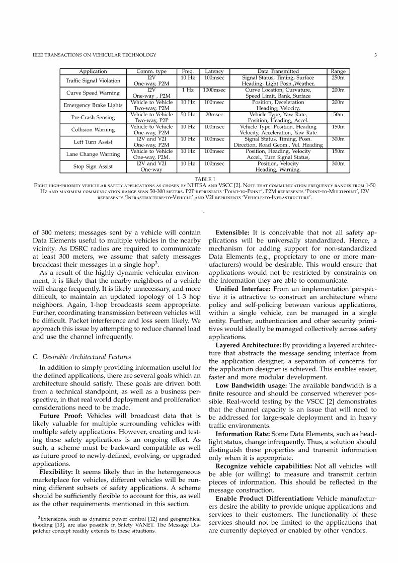
Fig. 1. The Message Dispatcher assimilates data requirements fromall the on-board applications and compiles a single message usinga dictionary of defined Data Elements and standardized messageconstruction guidelines. Some of the data may be obtained directlyby the MD from an onboard data source (e.g., CAN bus).
As described in the following sections, the MessageDispatcher architecture provides a sound and efficientarchitecture for the envisioned vehicular safety dataexchange environment.
III. MD
The basic architectural concept of the Message Dis-patcher (MD) is illustrated in Figures 1 and 2. TheMessage Dispatcher’s responsibility is to coordinate allthe data exchange requirements of the applications run-ning on a vehicle. The MD accomplishes this by servingas an interface between the application layer and thecommunication stack.Safety applications will register or send Data Elementsto be broadcasted to the MD. The MD then summarizesthese Data Elements across applications and creates asingle packet comprising the minimum set of the DataElements to be transmitted (See Figure 1). In some im-plementations the MD might collect data from other datasources within the vehicle (e.g., through the CAN bus).The MD would also consider data requirements of othersurrounding vehicles or roadside units, as described inSection III-C. This combined message is then sent to theDSRC radio for broadcast. Any vehicle that receives amessage would provide all on-board applications withthe Data Elements they require, as shown in Figure 2.The Message Dispatcher design can be divided intotwo broad topics. First, the definition of a Data ElementDictionary (Section III-A). Second, the specification ofhow these elements should be combined into a message(Section III-B).
A. Data Element Dictionary
This section describes how Data Elements are identi-fied and formatted. The section also describes the au-thors’ proposal for adding new elements to the DataElement dictionary. The SAE standard [11] identifies over70 data elements in its “Data Element Dictionary”. Eachelement in the dictionary is defined using the fieldsindicated in the example in Table II.
DispatcherMessage
Position, SpeedBrake Status
Brake StatusSpeed, Position
Application 1
Application 4
Application 5Position,
Acceleration.
Vehicle / OEM SpecificStandardized
Position, Speed,
Brake Status,
Acceleration.
Fig. 2. A receiving Message Dispatcher is responsible for separatingand disseminating Data Elements from the received message to allon-board applications, as well as managing data requirements forsurrounding vehicles.
Name DE VehicleLatitudeUnique ID 70Unit microdegrees
Accuracy LSB is 1 microdegreeRange -900000000 to 900000000Size 32bits
Description
The latitude position of the centerof the vehicle, expressed in microdegrees and based on the WGS-84
coordinate system.
TABLE IIA L D E.
Using this data dictionary, a message can be con-structed by creating a string of unique identifiers fol-lowed by the value of the Data Element. Further, thisunique ID overhead can be reduced when related DataElements are grouped into a “Data Frame”. For example,latitude is frequently updated and transmitted togetherwith longitude. Overhead is reduced by formatting lati-tude and longitude into a single “position” Data Framewith a single ID. Each Data Frame consists of DataElements in a specified order and thus their unique ID’sare not required within the Data Frame. Several dataframes have been defined in the SAE standard.Adding or modifying a Data Element under this ar-chitecture is relatively straight-forward. The data dic-tionary would need to be updated and re-submittedto a central authority (currently the SAE) for updatingthe standard. While waiting for the standards body toact, new elements can be introduced by a light-weighttagging scheme, which is discussed in Section III-B.
B. Message Construction
Each message is constructed using the Data Elementsand Data Frames specified by the data dictionary. Themessage dispatcher can choose to include (either in aFrame or as an individual Data Element) elements ina particular message so as to meet latency, networkloading or application demands.In the SAE standard [11], the message has been di-vided into three sections. The first section is used to in-clude Data Frames using their unique identifier followed
IEEE TRANSACTIONS ON VEHICULAR TECHNOLOGY 5
BRange of A
Range of BA C
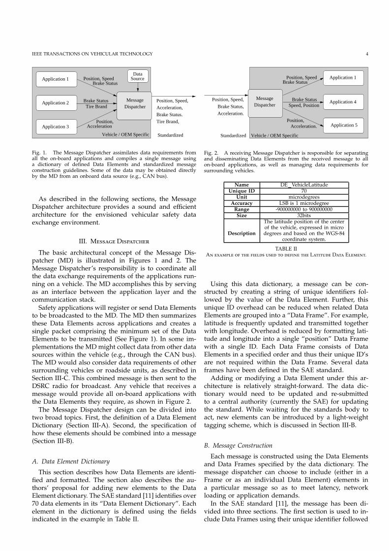
Fig. 3. Vehicle A sends a message that the Message Dispatcher onvehicle B matches on subsequent transmissions. Although Vehicle C isbeyond the range of interest of Vehicle A, it too begins to match themessage resulting in a “racing” condition.
by the series of Data Elements comprising the DataFrame. The second section is used to include individualData Elements that have not already been included inthe first section.The third section is reserved for the inclusion of ad-hoc or newly defined terms by using a lightweightlabeling scheme. The schema defines an escape characterwhich indicates the start of a Data Element, thus en-abling transmission of variable length data. The escapecharacter will immediately be followed by a uniquetag, of fixed length, that identifies the subsequent data.Using the tag the Message Dispatcher would poll thesubscribed applications for knowledge of the incomingData Element.
C. What and When to Send
Determining what elements are required to be sentby a vehicle in order to satisfy surrounding vehicles isa problem in SVANET. Within CAMP or SAE there isstill no way to obtain specific information from a newlyencountered vehicle. Sending a large packet, comprisingall defined Data Elements, at the maximum required rateamong all elements is very inefficient. While not themain contribution of this paper, we propose two possiblesolutions easily implemented under the MD architecture:
• Match Received Message: If a Message Dispatcherreceives a message with a Data Element it is not cur-rently transmitting, it should include its own versionof that data element in the following transmition.In this way it ‘matches’ the incoming message. Toavoid a “racing” situation shown in Figure 3, theoriginal sender includes a Data Element indicatingwhether its message contents should be matched.
• Request Data Elements: Define and send a Data Ele-ment that specifically requests certain elements. Thissolution would be useful in probe type applicationswhere a roadside unit requests information frompassing vehicles.
IV. E A
This section illustrates how the MD concept can beleveraged to efficiently construct a messages for mul-tiple safety applications. It further describes our MDimplemention. The two implemented safety applications,the Emergency Brake Warning (EBW) application andthe Intersection Violation Warning (IVW) application,are described (along with their data requirements) in
Driver unaware View is blocked Emergency Braking
123
(c) WITH EBW
EBW Warning Safe braking distance DSRC Warning sentreceived
Collision LATE Emergency Braking
3
2 1
(b) WITHOUT EBW
(a) BRAKING SITUATION
3 2 1
Non−DSRC vehicle
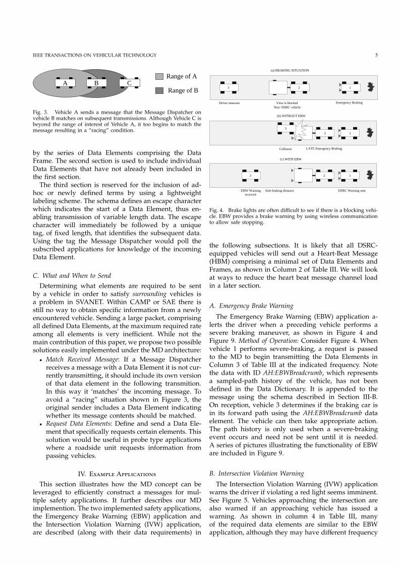
Fig. 4. Brake lights are often difficult to see if there is a blocking vehi-cle. EBW provides a brake warning by using wireless communicationto allow safe stopping.
the following subsections. It is likely that all DSRC-equipped vehicles will send out a Heart-Beat Message(HBM) comprising a minimal set of Data Elements andFrames, as shown in Column 2 of Table III. We will lookat ways to reduce the heart beat message channel loadin a later section.
A. Emergency Brake Warning
The Emergency Brake Warning (EBW) application a-lerts the driver when a preceding vehicle performs asevere braking maneuver, as shown in Figure 4 andFigure 9. Method of Operation: Consider Figure 4. Whenvehicle 1 performs severe-braking, a request is passedto the MD to begin transmitting the Data Elements inColumn 3 of Table III at the indicated frequency. Notethe data with ID AH:EBWBreadcrumb, which representsa sampled-path history of the vehicle, has not beendefined in the Data Dictionary. It is appended to themessage using the schema described in Section III-B.On reception, vehicle 3 determines if the braking car isin its forward path using the AH:EBWBreadcrumb dataelement. The vehicle can then take appropriate action.The path history is only used when a severe-brakingevent occurs and need not be sent until it is needed.A series of pictures illustrating the functionality of EBWare included in Figure 9.
B. Intersection Violation Warning
The Intersection Violation Warning (IVW) applicationwarns the driver if violating a red light seems imminent.See Figure 5. Vehicles approaching the intersection arealso warned if an approaching vehicle has issued awarning. As shown in column 4 in Table III, manyof the required data elements are similar to the EBWapplication, although they may have different frequency

IEEE TRANSACTIONS ON VEHICULAR TECHNOLOGY 6
requirements. Some data elements are unique to the IVWapplication and have not yet been defined in the DataDictionary (e.g. AH:IVWMap).
A
B B
A
Stop Signal
Collision
(a) No IVW (b) With IVW
Driver Alertedto missed signalUnnoticed
Fig. 5. Without IVW vehicle A runs the light and causes a collisionwith Vehicle B. When IVW is activated in figure (b), both drivers arealerted allowing Vehicle A to stop and Vehicle B to proceed cautiouslythrough the intersection
Method of Operation: Roadside units transmit trafficlight information including its location, light status, timetill color change, dimensions of intersection (called dataelement AH:IVWMap), etc. The IVW application registerswith the MD to receive all incoming IVW related DataElements. Vehicles then determine if a signal violationis imminent. If so, the driver is alerted and a messageis sent to the traffic light and surrounding vehiclesindicating that a violation is likely. Thus, the messagedispatcher only sends IVW data when triggered by aviolation event.
C. Message Composition
Consider a vehicle is speeding toward a red light. Thedriver has been alerted to a potential violation and isbraking sharply. Thus, both the IVW and EBW systemsare active. Table III lists a subset of the Data Elementsand transmit frequencies which the Message Dispatchermust satisfy.The Message Dispatcher combines the requiredData Frames and Data Elements into a minimal setof messages. Duplicates are ignored, such as withDE:Acceleration and DE:IVWWarningVehPos in Table III.Another example is data element DF:PositionShort whichis not included in outgoing messages as it is a subset ofthe information already included in DF:PositionLong.Since the applications have registered data at differentfrequencies, the MD constructs three different messages,called Msg10Hz, Msg5Hz and Msg3Hz. The messagecontents are described in the final 3 columns of Table III.Note that the Data Elements in the 10Hz message alsoappear in the 5Hz and 3Hz message. To meet the fre-quency requirements and minimize the utilized band-width, the MD will send the messages in the sequenceillustrated in Table IV.
D. Implementation
The Message Dispatcher has been implemented by theToyota Technical Center in two Toyota Prius cars. Each
Time (sec) Message Sent0.0 Msg3Hz0.1 Msg10Hz0.2 Msg5Hz (A)0.3 Msg10Hz0.4 Msg3Hz (B)0.5 Msg10Hz0.6 Msg5Hz0.7 Msg10Hz0.8 Msg5Hz0.9 Msg3Hz
TABLE IVT M
D T III. N () TM10H M5H. () TM5H M10H
M3H.
vehicle is retrofitted with a Linux-based miniature PC,an OBD-II vehicle interface, a DENSO prototype DSRCradio, and a commercial DGPS unit (See Figure 9(f)).The MD implementation uses a callback mechanismto interface with applications. Upon initialization, appli-cations register with the MD those Data Elements it willprovide and those it wants to receive from the MD. DataElements may be both provided and received. DuringData Element registration, the application supplies theMD with the callback method to be invoked when it istime to send the Data Element, or when the MD hasreceived an updated Data Element over the channel.At the end of the registration process, the applicationspecifies the frequency of transmission and informs theMD to begin a periodic transmission of these DataElements. The MD is then responsible for the messagecomposition detailed in Section IV-C, using the providedcallback method to get the Data Element values. Con-versely, the transmission of other registered Data Ele-ments may be event-driven. In this case, when the eventis triggered by the application logic, the application isresponsible for invoking a “Send Now” API in the MD.With both periodic and event-driven communicationspossible, the MD includes an internal scheduler to decidewhen to send periodic Data Elements. When interruptedby an event-triggered transmission, the MD schedulermay reschedule future periodic transmission times.The Toyota Technical Center has successfully imple-mented the MD described above in approximately 1000lines of code. It has been extensively tested while run-ning the EBW and IVW applications simultaneously. Forthese applications, a traffic light and two vehicles eachrun their own MD.
E. Analysis
A basic evaluation of the performance of the MDfor the two-applications in the TTC implementation isnow given. Using the Data Element sizes specified inSAE J2735 [11], the Heart-Beat Message is 25.5 bytes,Emergency Brake Warning message is 155.5 bytes, andthe Intersection Violation Warning message is 46.75

IEEE TRANSACTIONS ON VEHICULAR TECHNOLOGY 7
Data Element (DE) / Frame (DF) HBM EBW IVW Message Dispatcher 3 Hz 5 Hz 10 HzDF: PositionShort 3Hz 5 Hz 10 Hz In DE:PositionLong • • •
DF: AccelerationSet4Way 3Hz - 5 Hz 5 Hz • •
DF: PositionLong - 5 Hz 10 Hz 10 Hz • • •
DF: PositionConfidenceSet - 3 Hz 3 Hz 3 Hz •
DF: SpeedandHeadingPrecision 3Hz 5 Hz 5 Hz 5 Hz • •
DE: Acceleration - 3 Hz - In DF:AccelerationSet4WayDE: AntiLockBrakeStatus - 3 Hz - 3 Hz •
DE: BrakeAppliedStatus 3Hz 3 Hz - 3 Hz •
AH: EBWBreadcrumb - 5 Hz - 5 Hz & to EBW • •
DE: TrafficLightID - - - To IVWDF: TrafficLightLocation - - - To IVWDF: TrafficLightPhases - - - To IVWAH: IVWMap - - - To IVW
DE: IVWWarningFlag - - 10 Hz 10 Hz • • •
DE: IVWWarningID - - 10 Hz 10 Hz • • •
DE: IVWWarningVehPos - - 10 Hz In DF:PositionLong. . . - . . . . . . . . . . . . . . . . . .
TABLE IIIA D E (DE) F (DF) (E BW (EBW)
I VW (IVW)), H BM (HBM). C 5 M D
. C 6, 7 8 3, 5 10H S IV-C.
Message Type CMS MD& (Use Freq). Bandwidth E[Bandwidth]
Heart Beat (100%) 14.1 0.6 0.6EBW (2%) 14.1 6.2 0.71IVW (4%) 14.1 3.7 0.72
EBW & IVW (3%) 14.1 14.1 1.01
TABLE VC ( ) MD (MD) CM S (CMS) . T4th .
bytes.Message sizes are calculated without includingData Frame headers, Data Element identifiers, or anytagging schema. A Common Message Set that incorpo-rates all the Data Elements necessary for the HBM, EBW,and IVW is 176.75 bytes.
Assume that this Common Message Set (CMS) isperiodically transmitted with the highest frequency inTable III, 10Hz, in order to meet the requirements of allthe applications. For one vehicle, this requires a channelusage of 14.1kbps, as shown in Table V. Conversely, aHBM being sent out by the MD at the 3Hz frequencyspecified in Table III requires only 0.6kbps. This is areduction of 95% of channel load when neither of theapplications are required to transmit. Channel usagerises to 3.7kbps when IVW events occur (initiating a10Hz transmission) and to 6.2kbps when EBW eventsoccur (initiating a 5Hz transmission). If both IVW andEBW events occur on one vehicle, the channel usage isequal to that of the CMS. However, this assumes thatthe elements for either application are sent continuously.Since the MD can dynamically manage message con-tents, the full EBW/IVW message need only be sent inEBW/IVW instances, which we assume to occur with the(overly generous) percentage frequencies shown in theColumn 1 of Table V. Thus, the expected channel load,
shown in Column 3, is far less than the peak channelload.Further, it is significant to notice that additional savingwill be achieved in overall bandwidth usage when thereare multiple vehicles present. This is because, whenusing the MD, only a limited number of vehicles willneed to transmit a EBW or IVW message. The remainingvehicles continue to transmit the heart beat message.
Although these results depend on several simplifyingassumptions, it is clear that with a maximum DSRCchannel capacity of 27Mbps the reduction of channelload possible by employing the MD is relevant.In Section VI we shall present a further method forreducing the channel load which can readily be imple-mented in the Message Dispatcher framework.
V. D S
We have described our MD deployment and vehicletestbed in Section IV-D. Using the testbed we collectedseveral data sets under a variety of driving conditions.We have choosen three sets for further analysis. Thesets were all recorded in and around Ann Arbor, MI.The trajectories are shown in Figure 6, and describedin Table V. The data can be downloaded at [22]. Each
Parameter Data Set A Data Set B Data Set CEnvironment Urban Urban HighwaySample Freq. 5Hz 5Hz 5HzDuration 8min 24sec 10min 34sec 6min 17secLength 6.1km 7.6km 9.1km# of Stops 2 2 0# Turns 7 5 0
data set contains samples of vehicle position (latitudeand longitude), speed and acceleration (lateral and longi-tudinal). Other data such as brake status, brake pressureand steering wheel angle were also recorded.

IEEE TRANSACTIONS ON VEHICULAR TECHNOLOGY 8
−83.75 −83.74 −83.73 −83.72 −83.71 −83.7 −83.69 −83.6842.285
42.29
42.295
42.3
42.305
42.31
42.315
42.32
42.325
Longitude (Deg)
Latit
ude
(Deg
)
Fig. 6. Traces of the three recorded data sets. The lower trajectoryrepresents Data Set A, the middle Data Set B and the upper trajectoryis the Highway Data Set C.
VI. P C
The objective of this section is to show, using realworld data, that predictive coding can significantly re-duce the channel load in vehicular safety applications.The analysis thus far has basically been focused ontwo concepts:
1) Avoid duplication of data in multiple messages.2) Compose sequences of messages so as to only senddata at the minimum required update rate.
However, neither of these notions considers the un-certainty or variability associated with the underlyingdata. For example, analysis of the data sets reveals thatbrake status changes infrequently. When it does change,the status is often maintained. So, compared to vehi-cle longitude which changes rapidly and continuouslywhen a vehicle is moving, routine brake status can betransmitted less frequently. Only status changes needbe transmitted. Of course, upon a change, it can andshould be transmitted immediately. There is a differencebetween nominal state update transmission, and rapidreaction to changes.Indeed, we can extend this notion to encompass datawhich change frequently, but which can be easily pre-dicted. For example, given a particular vehicle position,velocity and steering angle, the future trajectory of thevehicle can be predicted. Hence, to extend the exampleabove, the longitude may not need to be transmittedfrequently either, if it can be predicted well. E.g. Astationary vehicles position can easily be predicted.The main idea presented in this section is to transmitdata only when the error in estimating the state is ‘suf-ficiently large’. We shall characterize the model used forthe state estimation as well as the notion of ‘sufficientlylarge error’. This idea is similar to conserving bandwidthwhile using computational power [15]. We also considerthe case when the error is small only the least significant
bits, or some smaller correction update is sent, ratherthan a complete data element with full resolution.These type of transmission policies represent Predic-tive Coding (PC), which we describe in the followingsection.
A. Predictive Coding
Linear Predictive Coding (LPC) [21] is commonly usedin the transmission, reproduction and generation of hu-man voice over low data rate channels. It is a methodof encoding signals in which the value of the signal ateach sample time is predicted as a linear function of thepast values of the signal [14]. Predictive Coding does notrequire the use of a linear prediction function.The design of a Predictive Coding scheme can bedivided into two parts. The first is to determine anappropriate model to be used to predict the signal whichis being sampled. In voice applications, a linear modelof a particular order is assumed. The model parametersare obtained using a least squares or auto-regressive fiton a window of sampled data. The model parameters(i.e., the coefficients of the characteristic polynomial andthe model gain) are then transmitted across the channel.In general, the order of the model is chosen so as to beable to accurately reproduce the signal given a particularmodel input. This is the second part of LPC design:specifying the model input. In voice applications, theinput is characterized by the voice pitch frequency. Anappropriate pulse train and white noise signal is used asa model input.Our approach differs from LPC in the following ways.First, our model is not linear. Second, we apriori definea Newtonian model to represent the behaviour of thevehicle. The model is described in Section VI-B. Bydefining the model apriori, we have specified the modelcoefficients. Thus, in our update scheme, we shall onlytransmit state updates, and not the model coefficients.Third, we do not characterize the input function at everytime instant, but rather assume a zero-order hold forintermediate values of the state which are not modeled.Finally, we do not choose a fixed sampling and transmitfrequency. Instead we shall dynamically choose a stateupdate frequency which ensures that the state estimateis always within some tolerable error bound.
B. System Model
In this section we describe a simple first order modelused for state prediction. We use the discrete time in-dex k. Transmission of a particular data element doesnot occur at fixed time intervals, but will occur at thediscretized time instants. Define the time between trans-mission instants as ∆k. We define the following velocityestimate update:
vk =
{
vk−1 + ak∆k when vk not transmitted,vk when vk is transmitted.
(1)
IEEE TRANSACTIONS ON VEHICULAR TECHNOLOGY 9
where v(k) and a(k) represent estimates of the velocity andacceleration at time k. The term vk represents the sampledvehicle velocity. The estimate of the distance, Dk, movedby the vehicle in time ∆k, is computed using
Dk = vk∆k + 0.5ak∆2k . (2)
The estimate of the vehicle heading, Φ, is updated usinga non-slip tri-cycle model:
Φk = Φk−1 −vk∆kltan Ψk−1, (3)
where Ψ is the angle of the front wheels and l is thewheel base of the vehicle. The angle of the front wheels islinearly related to the steering wheel angle, which we areable to measure. The distance moved, 2, is resolved intoa displacement using the most recent heading estimate.A longitude and latitude update can then be performedusing this displacement. Estimates for any other dataelement not included in the model are given by a zeroorder hold of the most recently transmitted value. Forexample, the acceleration estimate is updated as follows:
ak =
{
ak−1 when not braking,ak when ak transmitted.
(4)
Whenever a state observation is transmitted it replacesthe state estimate at that time, as illustrated by thevelocity update in (1).Our estimation model represents a Kalman Filter up-date scheme with noiseless observations. There is scopefor improvement in this regard by deploying a fullKalman filter, and using a higher dimensional modelfor state prediction and incorporating models for otherparameters. This is beyond our purpose here, whichis simply to demonstrate that using predictive codingyields a significant transmission data rate reduction forvehicular communication.
C. Tolerable Error
In Table III we have presented transmission frequen-cies for various data elements in two example appli-cations, as well as a ‘heart beat’ message. We refer tothese fixed frequency requirements as the ’regular trans-mission scheme’. To the best of the authors’ knowledge,selection of these frequency values in practice has beenbased on three requirements:
1) To provide neighbouring vehicles with a suffi-ciently accurate estimate of a vehicle’s currentstate. That is, to maintain the state estimation errorwithin some ‘tolerable error’.
2) Ensuring vehicles entering an area receive a timelyintroduction from their new neighbours.
3) Ensure that neighbours are quickly updated abouta state transition.
In the Predictive Coding scheme we propose here, thereis no requirement that data elements be transmitted ata particular frequency. Hence, the state estimation errorincurred between successive transmissions may be very
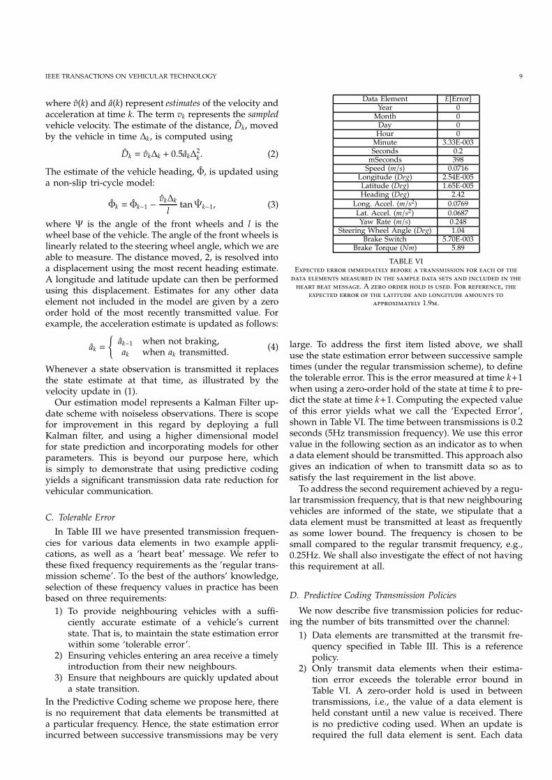
Data Element E[Error]Year 0Month 0Day 0Hour 0Minute 3.33E-003Seconds 0.2mSeconds 398Speed (m/s) 0.0716Longitude (Deg) 2.54E-005Latitude (Deg) 1.65E-005Heading (Deg) 2.42
Long. Accel. (m/s2) 0.0769
Lat. Accel. (m/s2) 0.0687Yaw Rate (m/s) 0.248
Steering Wheel Angle (Deg) 1.04Brake Switch 5.70E-003
Brake Torque (Nm) 5.89
TABLE VIE
. A . F ,
1.9.
large. To address the first item listed above, we shalluse the state estimation error between successive sampletimes (under the regular transmission scheme), to definethe tolerable error. This is the error measured at time k+1when using a zero-order hold of the state at time k to pre-dict the state at time k+1. Computing the expected valueof this error yields what we call the ‘Expected Error’,shown in Table VI. The time between transmissions is 0.2seconds (5Hz transmission frequency). We use this errorvalue in the following section as an indicator as to whena data element should be transmitted. This approach alsogives an indication of when to transmitt data so as tosatisfy the last requirement in the list above.To address the second requirement achieved by a regu-lar transmission frequency, that is that new neighbouringvehicles are informed of the state, we stipulate that adata element must be transmitted at least as frequentlyas some lower bound. The frequency is chosen to besmall compared to the regular transmit frequency, e.g.,0.25Hz. We shall also investigate the effect of not havingthis requirement at all.
D. Predictive Coding Transmission Policies
We now describe five transmission policies for reduc-ing the number of bits transmitted over the channel:
1) Data elements are transmitted at the transmit fre-quency specified in Table III. This is a referencepolicy.
2) Only transmit data elements when their estima-tion error exceeds the tolerable error bound inTable VI. A zero-order hold is used in betweentransmissions, i.e., the value of a data element isheld constant until a new value is received. Thereis no predictive coding used. When an update isrequired the full data element is sent. Each data
IEEE TRANSACTIONS ON VEHICULAR TECHNOLOGY 10
element must be sent at a frequency of at least0.25Hz.
3) Same as policy 2) except that the model describedin Section VI-B is used to predict the state inbetween sample transmissions. I.e., Predictive Cod-ing. When an update is required, the full dataelement is sent. Each data element must be sentat a frequency of at least 0.25Hz.
4) Same as in Policy 3), except that, when possible,a smaller state ’correction’ is sent instead of thefull data element. For example, when the erroris sufficiently small, instead of transmitting the 4byte Longitude data element, we transmit a 1 bytecorrection. A complete data element must be sent ata frequency of at least 0.25Hz.
5) Same as policy 4), except that there is no minimumupdate frequency requirement.
In all the policies, whenever a data element is sent thetime in millseconds must also be sent. We have usedthe data element definitions from the SAE standard [11].For our purposes here we shall consider how thesepolicies reduce the channel loading caused by a HeartBeat message transmitted at 5Hz, and containing all ofthe data listed in the left column of Table VI. Note thatthe data elements related to time (e.g., Year, hour, etc.)are included as time-stamp for the other Data Elementsin the packet, and is not for clock synchronization.
E. Predictive Coding Results
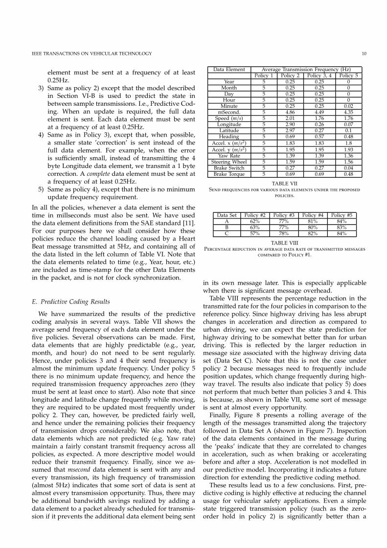
We have summarized the results of the predictivecoding analysis in several ways. Table VII shows theaverage send frequency of each data element under thefive policies. Several observations can be made. First,data elements that are highly predictable (e.g., year,month, and hour) do not need to be sent regularly.Hence, under policies 3 and 4 their send frequency isalmost the minimum update frequency. Under policy 5there is no minimum update frequency, and hence therequired transmission frequency approaches zero (theymust be sent at least once to start). Also note that sincelongitude and latitude change frequently while moving,they are required to be updated most frequently underpolicy 2. They can, however, be predicted fairly well,and hence under the remaining policies their frequencyof transmission drops considerably. We also note, thatdata elements which are not predicted (e.g. Yaw rate)maintain a fairly constant transmit frequency across allpolicies, as expected. A more descriptive model wouldreduce their transmit frequency. Finally, since we as-sumed that msecond data element is sent with any andevery transmission, its high frequency of transmission(almost 5Hz) indicates that some sort of data is sent atalmost every transmission opportunity. Thus, there maybe additional bandwidth savings realized by adding adata element to a packet already scheduled for transmis-sion if it prevents the additional data element being sent
Data Element Average Transmission Frequency (Hz)Policy 1 Policy 2 Policy 3, 4 Policy 5
Year 5 0.25 0.25 0Month 5 0.25 0.25 0Day 5 0.25 0.25 0Hour 5 0.25 0.25 0Minute 5 0.25 0.25 0.02mSecond. 5 4.86 4.49 4.35Speed (m/s) 5 2.01 1.76 1.76Longitude 5 2.90 0.26 0.07Latitude 5 2.97 0.27 0.1Heading 5 0.69 0.57 0.48
Accel. x (m/s2) 5 1.83 1.83 1.8
Accel. y (m/s2) 5 1.95 1.95 1.93Yaw Rate 5 1.39 1.39 1.36
Steering Wheel 5 1.59 1.59 1.56Brake Switch 5 0.27 0.27 0.04Brake Torque 5 0.69 0.69 0.48
TABLE VIIS
.
Data Set Policy #2 Policy #3 Policy #4 Policy #5A 62% 77% 81% 84%B 63% 77% 80% 83%C 57% 78% 82% 84%
TABLE VIIIP
P #1.
in its own message later. This is especially applicablewhen there is significant message overhead.Table VIII represents the percentage reduction in thetransmitted rate for the four policies in comparison to thereference policy. Since highway driving has less abruptchanges in acceleration and direction as compared tourban driving, we can expect the state prediction forhighway driving to be somewhat better than for urbandriving. This is reflected by the larger reduction inmessage size associated with the highway driving dataset (Data Set C). Note that this is not the case underpolicy 2 because messages need to frequently includeposition updates, which change frequently during high-way travel. The results also indicate that policy 5) doesnot perform that much better than policies 3 and 4. Thisis because, as shown in Table VII, some sort of messageis sent at almost every opportunity.Finally, Figure 8 presents a rolling average of thelength of the messages transmitted along the trajectoryfollowed in Data Set A (shown in Figure 7). Inspectionof the data elements contained in the message duringthe ‘peaks’ indicate that they are correlated to changesin acceleration, such as when braking or acceleratingbefore and after a stop. Acceleration is not modelled inour predictive model. Incorporating it indicates a futuredirection for extending the predictive coding method.These results lead us to a few conclusions. First, pre-dictive coding is highly effective at reducing the channelusage for vehicular safety applications. Even a simplestate triggered transmission policy (such as the zero-order hold in policy 2) is significantly better than a

IEEE TRANSACTIONS ON VEHICULAR TECHNOLOGY 11
0 50 100 150 200 250 300 350 400 450 5000
5
10
15
20
25
Time (sec)
Rol
ling
Ave
rage
of M
essa
ge L
engt
h
Stop 1
Turn D
Stop 2
Turn A
StartS−BendTurn B
Fig. 8. Representation of the length of messages transmitted along the route shown in Figure 7. A rolling average of 20 messages is used andthe length is defined as the number of characters transmitted in each message. The majority of the ‘spikes’ are caused by changes in acceleration,such as before and after a stop.
−83.75 −83.74 −83.73 −83.72 −83.71 −83.7
42.286
42.288
42.29
42.292
42.294
42.296
42.298
42.3
42.302
42.304
42.306
Longitude (Deg)
Latit
ude
(Deg
)
Turn D
START
Turn A
Turn B
Stop 1
S−Bend
Stop 2END
Fig. 7. The route corresponding to Data Set A. The points markedcorrespond to those in Figure 8.
regular high frequency transmission approach. Second,future message optimizations should focus on reducingthe number of transmitted messages, as compared totrying to reduce the size of individual messages.
VII. A A
In this section we describe how the goals identified inSection II-C are met by the MD architecture.Each application stipulates its data requirements toa single location, the Message Dispatcher. Thus, anyupgrades or modifications to the interface requirementsare well defined and localized (i.e., the single interfacegoal is met). The Message Dispatcher generates a com-bination message satisfying application requirements.
Applications do not consider how Data Elements areshared between vehicles, achieving an effective separa-tion of concerns. When the message format or protocolchanges, only the MD implementation must change, andnot the applications. This is an important abstraction forboth the application and communication layer designers.Algorithms for avoiding channel overload, secure datatransmission, and low latency message delivery can beimplemented in the Message Dispatcher enabling lowerbandwidth usage. Messages composed do not have tocontain redundant information and thus can recognizevehicle capabilities.The Message Dispatcher to evolve as application re-quirements change bBy using the flexible terminal char-acter with post-fixed identifier scheme. If a a uniqueor new set of Data Elements are required, these canbe incorporated only when required. This illustratesflexibility, future proof and extensibility of the architecture.This enables the MD to effectively exploit the communi-cation ability. Finally, since the applications have beensuccessfully separated from the communication protocol,companies are able to develop their own products andthus enable product differentiation.
VIII. C E
This paper provides an account of the current devel-opments and motivations of industry and governmentagency efforts to leverage VANET to create a new classof vehicular safety applications. Specific applicationsand their data and architectural requirements were de-scribed. Many of the application data requirements ei-ther partially or completely overlap. This motivated ourintroduction of the Message Dispatcher concept, which

IEEE TRANSACTIONS ON VEHICULAR TECHNOLOGY 12
leverages the Safety VANET environment and signifi-cantly improves efficiency of the wireless DSRC channel.We have presented the Toyota Technical Center testbedwhich we used to collect real world data for analysis.We proposed a predictive coding scheme for reducingchannel load and showed, based on our data, that usingeven a simple first order model can reduce channel loadby over 80%. We discussed how the MD architecturemeets several technical and business objectives and alsoenables other useful functionality.In addition to being adopted by the relevant SAE stan-dard, the Message Dispatcher has received wide appreci-ation among vehicle manufacturers. A current three yearCAMP project, funded by NHTSA, will demonstrate theMD in a demonstration project involving 5 automobilemanufacturers.There are several interesting research avenues openedand enabled by this architecture. For instance, chan-nel loading can now explicitly be managed throughdynamic message construction (e.g., based on vehicletraffic), packet collision avoidance algorithms can beimplemented (e.g. transmit power modulation), specific‘important’ data elements could be retransmitted in thecase of loss, cooperation between MD could be enabledto manage channel usage, enabling data delivery notifi-cations, giving priorities to information (e.g., low latencyor application dependencies), filtering or other modi-fications to the raw incoming data can be performedand even multi-hop information passing schemes canbe implemented. Extensions to our predictive codingapproach are also possible.
IX. A
From the Toyota Technical Center, the authors wishto thank Mike Samples and Mike James for their in-fluential discussions on architecture abstractions, andHideki Hada, Jeff Rogers, and Hemant Kowshik forthe contributions in TTC vehicle builds and demonstra-tions. Several other TTC staff made substantial efforts inprocuring and managing assets needed for our testbed.The authors also wish to thank Tom Schaffnit forhis support and guidance in bringing the Message Dis-patcher to the SAE standards process.
R
[1] A. Carter, “The status of vehicle-to-vehicle communication as ameans of improving crash prevention performance,” Tech. Rep.05-0264, NHTSA, 2005. http://www-nrd.nhtsa.dot.gov/pdf/nrd-01/esv/esv19/05-0264-W.pdf.
[2] “Vehicle safety communications project-final report,” Tech.Rep. HS 810 591, USDOT, April 2006. http://www-nrd.nhtsa.dot.gov/departments/nrd-12/pubs rev.html.
[3] “Traffic safety facts,” Tech. Rep. Report DOT HS 809 767, NHTSA,http://www-nrd.nhtsa.dot.gov, 2003.
[4] “U.S. Transp. Sec. Mineta announces opening of crash preventingintelligent intersection test facility.” Press Release, 23 June 2003.http://www.its.dot.gov/press/fhw2003.htm.
[5] J. Paniati, “Intelligent safety efforts inAmerica.” Presentation, November 2003.http://www.its.dot.gov/speeches/madridvii2003.ppt.
[6] CARE, “Community road accident database,” 2004.http://europa.eu.int/comm/transport/care/.
[7] Toyota Motor Corp., “Toyota safety: Toward realizingzero fatalities and accidents.” Presentation, 2004.http://www.toyota.co.jp/en/safety presen/index.html.
[8] “Standard specification for telecommunications and informationexchange between roadside and vehicle system - 5GHz banddedicated short range communications (DSRC) medium accesscontrol (MAC) and physical layer (PHY) specifications,” Tech.Rep. ASTM E2213-03, ASTM, September 2003.
[9] “Report and order,” Tech. Rep. FCC 03-324, USFCC, December2003.
[10] “IEEE DSRC standards group meetings.” Meeting Minutes.www.leearmstrong.com/DSRC/DSRCHomeset.htm.
[11] “Dedicated short range message set (DSRC) dictionary,” Tech.Rep. Standard J2735, SAE, 2006.
[12] V. Kawadia and P. Kumar, “Principles and protocols for powercontrol in ad hoc networks,” in IEEE Journal on Selected Areas inCommunications, vol. 23, pp. 76–88, January 2005.
[13] Y.-B. Ko and N. Vaidya, “Geocasting in mobile ad hoc net-works: Location-based multicast algorithms,” in WMCSA, (NewOrleans), 1999.
[14] American National Standards Inc., “ATIS Telecom Glossary 2000,”at http://www.atis.org/tg2k/t1g2k.html.
[15] J. K. Yook, D. M. Tilbury, N. R. Soparkar, “Trading Computationfor Bandwidth: Reducing communication in Distributed ControlSystems Using State Estimators” in IEEE Transactions on ControlSystems Technology, vol. 10, no. 4, pp. 503-518, 2002.
[16] C. L. Robinson, L. Caminiti, D. Cavney and K. Laberteaux,“Efficient coordination and transmission of data for vehicularsafety applications”, in The Third ACM International Workshop onVehicular Ad Hoc Networks (VANET), pp. 10-19, 2006.
[17] www-nrd.nhtsa.dot.gov/pdf/nrd-12/CAMP3/images/CAMP-IVIThirdAnnualReport.pdf
[18] www-nrd.nhtsa.dot.gov/pdf/nrd-12/CAMP3/images/CAMP-IVIThirdAnnualReport.pdf
[19] http://www.car-2-car.org/[20] http://www.mlit.go.jp/[21] P. Elias, “Predictive coding I”, in IEEE Transactions on Information
Theory,, vol. IT-1, no. 1, pp/ 16-24, March 1955.[22] http://decision.csl.uiuc.edu/ testbed/TTCUIUCData.zip
Craig Robinson received a B.Sc. E. degree fromthe University of the Witwatersrand, SouthAfrica in 2000. He was awarded a FulbrightScholarhip in 2001 under which he completedhis M.Sc. at the University of Illinois at Ur-bana Champaign (UIUC) in 2003. He is cur-rently completing his Ph.D. at UIUC in theIndustrial and Enterprise Systems EngineeringDepartment. His research interests include per-formance in networked control systems, esti-mation and control in wireless communication
environments and designing system architecture for such systems.
D. Caveney received his B.Sc.E degree in Ap-plied Mathematics from Queen’s University inKingston, Ontario, Canada in 1999 and hisM.Sc. and Ph.D. degrees in Mechanical En-gineering from the University of California,Berkeley, in 2001 and 2004, respectively. He thenacted as a Visiting Postdoctoral Scholar with theCenter for Collaborative Control of UnmannedVehicles at the University of California, Berke-ley for 2004 to 2005. Since 2005, Dr. Caveneyhas been a Senior Research Scientist with the
Toyota Technical Center in Ann Arbor, Michigan, where his interestsinclude cooperative control of vehicles for safety and mobility.

IEEE TRANSACTIONS ON VEHICULAR TECHNOLOGY 13
(a) Three cars in transit. View of frontvehicle is obscured.
(b) Middle vehicle swerves to avoidbraking front vehicle.
(c) Without EBW, emergency brakingis required to stop the last vehicle.
(d) With EBW, driver is alerted as thebraking occurs and starts to brake.
(e) Safe stopping distance achieved. (f) System hardware
Fig. 9. Illustration of the functionality of the Emergency Brake Warning (EBW) system. Figures (a), (b) and (c) represent behaviour without theEBW system. Three vehicles are traveling at high speed are shown in Figure (a). The front vehicle begins to brake sharply (Figure (b)) causingthe middle vehicle to swerve at the last moment. The result is emergency braking and a potential collision by the rear vehicle in Figure (c).Alternatively, with EBW in Figure (d), as soon as the front car begins braking an EBW is transmitted via DSRC to the rear vehicle where thedriver is alerted through the LCD screen, as well as via an alarm over the audio system. Ample time is then available for the tail vehicle tostop as shown in Figure (e). Figure (f) shows the hardware deployed in the rear of a Toyota Prius. The CAN network is accessed on the lefthand side, a GPS receiver is in the middle and the DSRC radio as well as the mini computer are on the right hand side.
Lorenzo Caminiti is a Sr. Engineer at the ToyotaTechnical Center. His current research interestsinclude the creation and validation of advancedvehicular active safety systems. He received hismasters in engineering from the University ofRome. He has extended experience in softwaredesign and development for embedded andnetworked systems.
Girish Baliga developed a middleware frame-work for networked control systems under theguidance of Prof. P. R. Kumar for his PhD inComputer Science at the University of Illinois atUrbana-Champaign. He also received an MS inComputer Science and an MS in Mathematicsfrom the University of Illinois, and a B. Techin Computer Engineering from the NationalInstitute of Technology, Surathkal, India. He iscurrently a Software Engineer in the SystemInfrastructure Group at Google, Inc.
Ken Laberteaux is a Senior Principal ResearchEngineer for the Toyota Technical Center in AnnArbor, MI. Dr. Laberteaux’s research focus isinformation-rich vehicular safety systems, fo-cusing on architecture and protocol design forvehicle-to-vehicle and vehicle-to-roadside wire-less communication. He is one of the foundersand two-year (2004, 2005) General Co-Chairof the highly-selective, international Vehicu-lar Adhoc Networks (VANET) workshop. Dr.Laberteaux serves as the technical lead for
communications of the multi-year, multi-million dollar Vehicle SafetyCommunications-Applications collaboration project between the USGovernment and several automotive companies.
P. R. Kumar is the Franklin W. Woeltge Profes-sor of Electrical and Computer Engineering atthe University of Illinois, Urbana-Champaign.He is a Fellow of the IEEE, a recipient of theDonald P. Eckman Award of the American Au-tomatic Control Council, the IEEE Field Awardin Control Systems, the IEEE CommunicationsSociety Fred W. Ellersick Prize, and a memberof the National Academy of Engineering, U.S.A.He has worked on problems in game theory,adaptive control, stochastic systems, simulated
annealing, neural networks, machine learning, queuing networks,manufacturing systems, scheduling, and wafer fabrication plants. Hiscurrent research interests are in wireless networks, sensor networks,and the convergence of control, communication and computation.