IEEE TRANSACTIONS ON ROBOTICS, VOL. 21, NO. 1, …IEEE TRANSACTIONS ON ROBOTICS, VOL. 21, NO. 1,...
9
IEEE TRANSACTIONS ON ROBOTICS, VOL. 21, NO. 1, FEBRUARY 2005 93 Revisiting Trilateration for Robot Localization Federico Thomas and Lluís Ros Abstract—Locating a robot from its distances, or range mea- surements, to three other known points or stations is a common operation, known as trilateration. This problem has been tra- ditionally solved either by algebraic or numerical methods. An approach that avoids the direct algebrization of the problem is proposed here. Using constructive geometric arguments, a coordi- nate-free formula containing a small number of Cayley–Menger determinants is derived. This formulation accommodates a more thorough investigation of the effects caused by all possible sources of error, including round-off errors, for the first time in this context. New formulas for the variance and bias of the unknown robot location estimation, due to station location and range mea- surements errors, are derived and analyzed. They are proved to be more tractable compared with previous ones, because all their terms have geometric meaning, allowing a simple analysis of their asymptotic behavior near singularities. Index Terms—Cayley–Menger determinants, error analysis, nu- merical conditioning, robot localization, trilateration. I. INTRODUCTION T RILATERATION is a method to determine the position of an object based on simultaneous range measurements from three stations located at known sites. This is a common opera- tion not only in robot localization [20], but also in kinematics [2], [22], aeronautics [17], crystallography [16], and computer graphics [8]. It can be trivially expressed as the problem of finding the intersection of three spheres, that is, finding the so- lutions to the following system of quadratic equations: (1) where , are the coordinates of station , and is the range measurement associated with it. In Fig. 1, thick segments between stations define the base plane, and thin ones, those connecting the moving object and the stations, cor- respond to the range measurements. The problem of intersecting three spheres can be easily re- duced to that of obtaining the intersection of a line and a sphere. Indeed, system (1) can be simplified into the following system of Manuscript received September 26, 2003; revised May 4, 2004. This paper was recommended for publication by Associate Editor Z. Li and Editor S. Hutchinson upon evaluation of the reviewers’ comments. This work was supported in part by the Spanish CICyT under Contract TIC2003-03396. The work of L. Ros was supported by a Ramón y Cajal contract from the Spanish Ministry of Education and Science. The authors are with the Institut de Robòtica i Informàtica Industrial (CSIC- UPC), 08028 Barcelona, Spain (e-mail: [email protected]; [email protected]). Digital Object Identifier 10.1109/TRO.2004.833793 Fig. 1. The trilateration problem consists of obtaining the location of a mobile robot from its distance to three stations (located at , , and ). two linear equations, whose solution is a line, and one quadratic equation: (2) where and . The most straightforward way to obtain the two linear equa- tions in (2) consists of subtracting the second and third equations from the first in (1), respectively, so that the quadratic terms cancel [8], [17], though other alternatives are possible [2]. Further simplifications are still possible by expressing the sta- tion coordinates according to a specific coordinate frame [9]. For example, by making the XY plane of the reference frame be the base plane, or making one coordinate axis coincide with the baseline between two stations, or simply locating the origin at one station. Nevertheless, this kind of simplification has an important drawback. If any other frame has to be used, a trans- formation has to be applied and, what is more important, the nu- merical conditioning of the resulting formulation depends on the chosen reference frame. This is why those formulations which are not linked to a particular reference frame, or coordinate- free formulations, are preferable. Available closed-form formu- lations of this kind directly take as input either system (1) [4] or (2) [17] and, despite their apparent simplicity, the expres- sions can be quite involved, in particular, those presented in [17], which are the standard formulas used in robotics [20]. In all cases, the results are obtained, apart from a square root, by employing standard techniques from linear algebra. 1552-3098/$20.00 © 2005 IEEE Authorized licensed use limited to: UNIVERSITAT POLITÈCNICA DE CATALUNYA. Downloaded on September 22, 2009 at 04:20 from IEEE Xplore. Restrictions apply.
Transcript of IEEE TRANSACTIONS ON ROBOTICS, VOL. 21, NO. 1, …IEEE TRANSACTIONS ON ROBOTICS, VOL. 21, NO. 1,...

IEEE TRANSACTIONS ON ROBOTICS, VOL. 21, NO. 1, FEBRUARY 2005 93
Revisiting Trilateration for Robot LocalizationFederico Thomas and Lluís Ros
Abstract—Locating a robot from its distances, or range mea-surements, to three other known points or stations is a commonoperation, known as trilateration. This problem has been tra-ditionally solved either by algebraic or numerical methods. Anapproach that avoids the direct algebrization of the problem isproposed here. Using constructive geometric arguments, a coordi-nate-free formula containing a small number of Cayley–Mengerdeterminants is derived. This formulation accommodates a morethorough investigation of the effects caused by all possible sourcesof error, including round-off errors, for the first time in thiscontext. New formulas for the variance and bias of the unknownrobot location estimation, due to station location and range mea-surements errors, are derived and analyzed. They are proved tobe more tractable compared with previous ones, because all theirterms have geometric meaning, allowing a simple analysis of theirasymptotic behavior near singularities.
Index Terms—Cayley–Menger determinants, error analysis, nu-merical conditioning, robot localization, trilateration.
I. INTRODUCTION
T RILATERATION is a method to determine the position ofan object based on simultaneous range measurements from
three stations located at known sites. This is a common opera-tion not only in robot localization [20], but also in kinematics[2], [22], aeronautics [17], crystallography [16], and computergraphics [8]. It can be trivially expressed as the problem offinding the intersection of three spheres, that is, finding the so-lutions to the following system of quadratic equations:
(1)
where , are the coordinates of station, and is the range measurement associated with it. In Fig. 1,
thick segments between stations define the base plane, and thinones, those connecting the moving object and the stations, cor-respond to the range measurements.
The problem of intersecting three spheres can be easily re-duced to that of obtaining the intersection of a line and a sphere.Indeed, system (1) can be simplified into the following system of
Manuscript received September 26, 2003; revised May 4, 2004. This paperwas recommended for publication by Associate Editor Z. Li and EditorS. Hutchinson upon evaluation of the reviewers’ comments. This work wassupported in part by the Spanish CICyT under Contract TIC2003-03396. Thework of L. Ros was supported by a Ramón y Cajal contract from the SpanishMinistry of Education and Science.
The authors are with the Institut de Robòtica i Informàtica Industrial (CSIC-UPC), 08028 Barcelona, Spain (e-mail: [email protected]; [email protected]).
Digital Object Identifier 10.1109/TRO.2004.833793
Fig. 1. The trilateration problem consists of obtaining the location of a mobilerobot from its distance to three stations (located at , , and ).
two linear equations, whose solution is a line, and one quadraticequation:
(2)
where and .The most straightforward way to obtain the two linear equa-
tions in (2) consists of subtracting the second and third equationsfrom the first in (1), respectively, so that the quadratic termscancel [8], [17], though other alternatives are possible [2].
Further simplifications are still possible by expressing the sta-tion coordinates according to a specific coordinate frame [9].For example, by making the XY plane of the reference framebe the base plane, or making one coordinate axis coincide withthe baseline between two stations, or simply locating the originat one station. Nevertheless, this kind of simplification has animportant drawback. If any other frame has to be used, a trans-formation has to be applied and, what is more important, the nu-merical conditioning of the resulting formulation depends on thechosen reference frame. This is why those formulations whichare not linked to a particular reference frame, or coordinate-free formulations, are preferable. Available closed-form formu-lations of this kind directly take as input either system (1) [4]or (2) [17] and, despite their apparent simplicity, the expres-sions can be quite involved, in particular, those presented in[17], which are the standard formulas used in robotics [20]. Inall cases, the results are obtained, apart from a square root, byemploying standard techniques from linear algebra.
1552-3098/$20.00 © 2005 IEEE
Authorized licensed use limited to: UNIVERSITAT POLITÈCNICA DE CATALUNYA. Downloaded on September 22, 2009 at 04:20 from IEEE Xplore. Restrictions apply.
94 IEEE TRANSACTIONS ON ROBOTICS, VOL. 21, NO. 1, FEBRUARY 2005
As an alternative to closed-form formulations, there alsoexist numerical resolution methods for the trilateration problem.They take an approximation of the object position and itera-tively achieve a better estimation by linearizing the measure-ment equations [10]. When analyzing what kind of influencethe different sources of error have on the estimations, numericalapproaches are of little help, so that closed-form formulationsare obviously preferable.
In some applications, the range measurements or the stationlocations may not be known accurately, and this can lead to diffi-culties, particularly near singularities of the Jacobian of system(1), which correspond to locations in which the moving objectis close to the base plane or the three stations are nearly aligned.Hereafter, these configurations will be referred to as singulari-ties. In such cases, the problem can be formulated as a nonlinearleast-squares problem to identify the best approximate solution[4]. Under these circumstances, it seems inevitable to rely on anumerical approach, because a closed-form formulation mightyield no solution.
We propose here an alternative approach to previous closed-form formulations that avoids the algebrization of the problemgiven by (1) or (2). Instead, by using barycentric coordinates, wederive a formula containing a few number of Cayley–Mengerdeterminants, all of them having a geometric interpretation interms of squared volumes, areas, or lengths. In this formulation,the station location coordinates appear explicitly as vectors, al-lowing a simple analysis of the effects caused by errors in theselocations. In general, the analysis of how the different errorscontribute to the estimation error, and how this error behavesnear a singularity, is straightforward.
The paper is organized as follows. Section II presents somebasic properties of Cayley–Menger determinants related to thegeometry of tetrahedra, which are the key elements for the newvectorial coordinate-free solution to the trilateration problempresented in Section III. Based on this formulation, a completeerror analysis of the trilateration operation is then given in Sec-tion IV. This analysis includes the study of the effects caused byrange and station location errors in terms of variances and biaserrors in the results. Section V is a digression on the minimiza-tion of the effects caused by roundoff errors when using limitedcomputational resources and, finally, Section VI summarizes themain contributions and points that deserve further research.
II. CAYLEY–MENGER DETERMINANTS
The Cayley–Menger bideterminant of two sequences ofpoints, and , is defined as
......
.... . .
...
where denotes the squared distance between thepoints and . This determinant plays a fundamental role inthe so-called “distance geometry,” a term coined by Blumen-thal in [1] which refers to the analytical study of Euclideangeometry in terms of invariants, without resorting to artificialcoordinate systems. Since in many cases of interest the twosequences of points are the same, it will be convenient to abbre-viate by , which issimply called a Cayley–Menger determinant. Next, we give thegeometric interpretation of these determinants for .For further details, the reader is referred to [6, pp. 126–129]and [12].
As for the Cayley–Menger determinants, it can be shown thatis times the squared hypervolume of
the simplex spanned by the points in . Hence,for
where is the Euclidean distance between and. Observe that the use of the symbol for both
the squared distance from to and their Cayley–Mengerdeterminant is thus consistent.
For , if is the area of the triangle spanned by , ,and , we obtain Herron’s formula relating with the sidelengths
(3)
For , if is the volume of the tetrahedron spanned by, , , and , we obtain Euler’s formula, relating to the
edge lengths
(4)
For the Cayley–Menger bideterminants, it can be shown that,for
Since this dot product can be expressed as, with being the angle be-
tween the lines supporting the segments and , thisyields the following formula for , in terms of the sixinterpoint distances:
By expanding in terms of the involved dis-tances, the reader can easily see that when , this for-mula reduces to the law of cosines for a triangle.
Likewise, for , it can be shown that
The right-hand side (RHS) of this equation can be easilyshown to be equal to , where and arethe areas of the triangles and , respectively,
Authorized licensed use limited to: UNIVERSITAT POLITÈCNICA DE CATALUNYA. Downloaded on September 22, 2009 at 04:20 from IEEE Xplore. Restrictions apply.

THOMAS AND ROS: REVISITING TRILATERATION FOR ROBOT LOCALIZATION 95
Fig. 2. An interior dihedral angle of the tetrahedron defined by , , ,and .
and is the dihedral angle between the planes they define. Byexpressing these areas as Cayley–Menger determinants of thetriangles’ vertices, this yields the following formula for thecosine of , in terms of interpoint distances:
(5)
which can be regarded as the law of cosines generalized to atetrahedron when and (see Fig. 2). In otherwords
(6)
An alternative formulation for the law of cosines generalizedto a tetrahedron can be found in [15], which permits alterna-tively expressing as
(7)
Identifying the RHSs of (6) and (7), we get
(8)
which will be useful later.Finally, for , the bideterminant is equal to the product
of two triple products
and hence, it can be interpreted as 36 times the product of thevolumes of the tetrahedra , , , , and , , , .
III. A NEW FORMULATION FOR TRILATERATION
Given three points in space, say , , and , the tri-lateration problem consists of finding the location of anotherpoint, say , whose distance to these three points is known.According to Fig. 3, using barycentric coordinates [5, pp.216–221], the location of the orthogonal projection of ontothe base, say , can be expressed as
Fig. 3. Barycentric coordinates of the projection of onto the plane definedby , , and .
where , , and are the signed areas1 of the triangles, , and , respectively, and is the area of
the triangle . Alternatively
where and .The values can be obtained by projecting the areas of the
triangles coincident in , onto the base plane. Hence, using (3)
where and are the dihedral angles indicated in Fig. 3.Moreover, using (5), we can write
where
Now, can be obtained as
(9)
where the sign accounts for the two mirror symmetric loca-tions of with respect to the base plane, and is equal to theheight of the tetrahedron, divided by the norm of .
1For a triangle in the Euclidean plane with area , the signed area isdefined as (respectively, ) if the point is to the right (resp. to the left)of the line , when going from to .
Authorized licensed use limited to: UNIVERSITAT POLITÈCNICA DE CATALUNYA. Downloaded on September 22, 2009 at 04:20 from IEEE Xplore. Restrictions apply.

96 IEEE TRANSACTIONS ON ROBOTICS, VOL. 21, NO. 1, FEBRUARY 2005
Since the volume of the tetrahedron is , using (3) and(4), we can write
(10)
Moreover, again using (3)
(11)
one concludes that
Hence, the final expression for is
(12)
This formula can be easily rewritten in matrix form as
(13)
where , , and are appropriate constant matrices andvectors involving cofactors of ,
, and . This formcoincides with Manolakis’ expression, given in [17], consideredas the computationally most efficient formula for trilaterationand used in robot localization [20]. While obtaining (13) from(12) is straightforward, the converse is by no means obvious.
The main advantage of (12) over (13) is that it is mathe-matically more tractable, because all terms are determinantswith geometric meaning. For example, (12) permits realizingthat only when , i.e., when , , andare aligned, the location of is undefined, and only when
, i.e., when lies on the base plane,the solution for is unique. This kind of reasoning cannot becarried out on (13).
IV. ERROR ANALYSIS
This section shows how (12) accommodates a more thorougherror analysis than previously done for the trilateration problem.Under the assumption that both the station locations and rangemeasurements are corrupted by zero-mean uncorrelated randomnoise with a Gaussian probability density function, explicit ex-pressions for the variance and bias errors of the object locationestimation are obtained in terms of squared distances, areas, andvolumes.
A. Station Location Errors
The station location error analysis given in [18] requires theinversion of the Jacobian matrix resulting from the linearizationof system (1). Unfortunately, this inversion becomes ill-condi-tioned near a singularity. We can take full advantage of (12),
though, to avoid this inversion. Since (12) is linear with respectto each station location, it allows us to prove that when stationlocations errors are the only source of error, the object locationestimation is unbiased, despite all involved nonlinearities. Also,its associated covariance matrix has a simple expression in termsof lengths, areas, and volumes.
Let and denote the additive random error and the ac-tual value of station location , , respectively. Then,
. These errors are assumed to have zero-meanvalue, that is , where stands for the expectedvalue operation. We also assume that their three coordinates areuncorrelated with the same variance for the three stations. Inother words
ifif
(14)
where denotes the identity matrix. Then, using (12), it is easyto check that
(15)
where and . Then, the biaserror due to the error in the location of the stations can be statedas follows:
which is identically zero because all scalar products requiredto compute the above cross products involve uncorrelatedrandom variables (reminding that if two Gaussian variables,say and , are uncorrelated, they are independent, that is,
).In turn, the covariance matrix of the position estimate error
can be evaluated as
Then, after expanding the above expected value operation andremoving expected values involving products of uncorrelatedvariables, we have
where . That is
(16)where , , and .
Authorized licensed use limited to: UNIVERSITAT POLITÈCNICA DE CATALUNYA. Downloaded on September 22, 2009 at 04:20 from IEEE Xplore. Restrictions apply.

THOMAS AND ROS: REVISITING TRILATERATION FOR ROBOT LOCALIZATION 97
Fig. 4. Relative error in the robot location for two representativecases (see text for details).
The resulting covariance matrix is isotropic: the variance inthe robot location is the same along any direction, say . Then
(17)Finally, in terms of volume, areas, and lengths, we have
(18)
Assuming that the three stations are not aligned, for high dis-tances to the base plane, (18) can be approximated by
(19)
and for low distances by
(20)
Fig. 4 examines this relative error for two representativecases. In the first case, the three stations form an equilateraltriangle on the XY plane inscribed in a circle centered inthe origin of radius 1000 distance units. The locations of the
stations are , ,and . The data-acquisition area of thesystem is a square area at a distance of 8000 units from the baseplane, spanning in each direction from 4000 to 4000 units[see Fig. 4(a)]. In the second case, the stations are located at
, , and ,i.e., they are almost aligned along the X axis. The acquisitionarea in this case is on the base plane itself [see Fig. 4(b)]. Weobserve that while in Fig. 4(a), the error increases as we moveaway from the stations’ barycenter, in Fig. 4(b), a privilegeddirection of low error arises coinciding with the axis alongwhich the sum in (20) is minimum.
Although the error analysis given in [18] is not carried out forGaussian error distributions, the provided results are consistentwith the results obtained here for the first case. The results of thesecond case cannot be compared with previous results, becauseit corresponds to a singularity in which the robot is located onthe base plane, which cannot be treated by previous formula-tions.
B. Range Measurement Errors
The error analysis given here for the range measurements isparallel to that presented in [17]. We adapt it to our formulation,showing that the same results can be obtained in a more conciseform.
Let and denote the additive random error and theactual value of range measurement , respectively. Let
and . Then, .The range errors are assumed to have zero-mean value, that is
. We also assume that they are uncorrelated with thesame variance . Consequently, their covariance matrix can beexpressed as
(21)
For small range errors, the robot location can be well ap-proximated by retaining the terms up to the second-order partialderivatives in the Taylor expansion of (9), that is
Then the expected value of robot location error, i.e., the biaserror, is
Using (21)
Finally, substituting (12)
(22)
where , andthe or sign is used, depending on the chosen trilateration
Authorized licensed use limited to: UNIVERSITAT POLITÈCNICA DE CATALUNYA. Downloaded on September 22, 2009 at 04:20 from IEEE Xplore. Restrictions apply.
98 IEEE TRANSACTIONS ON ROBOTICS, VOL. 21, NO. 1, FEBRUARY 2005
solution. The analytic expression for these derivatives can befound in Appendix I.
As we already mentioned, the trilateration bias error was al-ready examined in [17], where two main results were drawn:
(R1) projection of the bias error onto the base plane can beneglected;
(R2) bias error becomes relevant as the robot location ap-proaches the base plane.
Contrary to all other formulations, these two facts have a di-rect accommodation in ours. It is important to realize thatand are constant, i.e., the bias error parallel to the baseplane is constant, independent of the robot location. This con-tradicts, in part, the results presented in [17]. Nevertheless, thishas no practical effects because, as a consequence of (R1),and can be neglected in front of , and (22) can be ap-proximated by
(23)
As a consequence of (R2), this can be further simplified, forlow distances to the base plane, into (see Appendix I for thedetails)
(24)
This equation is remarkable because of its simplicity, whencompared with its counterpart in [17].
It can be checked that, as a consequence of this error, whenthe robot moves on a plane parallel to the base plane, the estima-tion will erroneously indicate that it increases and decreases itsdistance to this plane when it approaches, and goes away from,the barycenter of the stations, respectively.
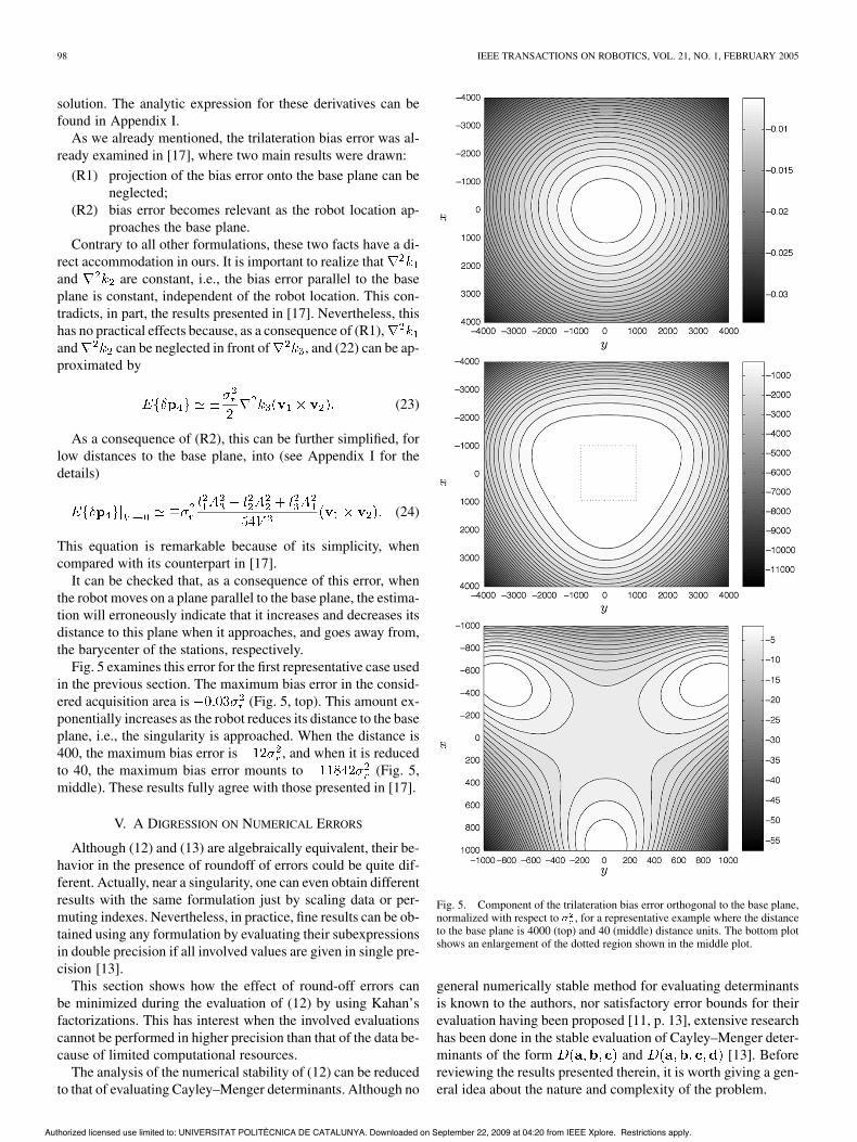
Fig. 5 examines this error for the first representative case usedin the previous section. The maximum bias error in the consid-ered acquisition area is (Fig. 5, top). This amount ex-ponentially increases as the robot reduces its distance to the baseplane, i.e., the singularity is approached. When the distance is400, the maximum bias error is , and when it is reducedto 40, the maximum bias error mounts to (Fig. 5,middle). These results fully agree with those presented in [17].
V. A DIGRESSION ON NUMERICAL ERRORS
Although (12) and (13) are algebraically equivalent, their be-havior in the presence of roundoff of errors could be quite dif-ferent. Actually, near a singularity, one can even obtain differentresults with the same formulation just by scaling data or per-muting indexes. Nevertheless, in practice, fine results can be ob-tained using any formulation by evaluating their subexpressionsin double precision if all involved values are given in single pre-cision [13].
This section shows how the effect of round-off errors canbe minimized during the evaluation of (12) by using Kahan’sfactorizations. This has interest when the involved evaluationscannot be performed in higher precision than that of the data be-cause of limited computational resources.
The analysis of the numerical stability of (12) can be reducedto that of evaluating Cayley–Menger determinants. Although no
Fig. 5. Component of the trilateration bias error orthogonal to the base plane,normalized with respect to , for a representative example where the distanceto the base plane is 4000 (top) and 40 (middle) distance units. The bottom plotshows an enlargement of the dotted region shown in the middle plot.
general numerically stable method for evaluating determinantsis known to the authors, nor satisfactory error bounds for theirevaluation having been proposed [11, p. 13], extensive researchhas been done in the stable evaluation of Cayley–Menger deter-minants of the form and [13]. Beforereviewing the results presented therein, it is worth giving a gen-eral idea about the nature and complexity of the problem.
Authorized licensed use limited to: UNIVERSITAT POLITÈCNICA DE CATALUNYA. Downloaded on September 22, 2009 at 04:20 from IEEE Xplore. Restrictions apply.

THOMAS AND ROS: REVISITING TRILATERATION FOR ROBOT LOCALIZATION 99
The direct expansion of a determinant leads to terms.The way these terms are added is fundamental to attaining highnumerical stability. Following the discussion given in [11], con-sider the substraction, in exact arithmetic, , where
and . The terms and arerelative errors or uncertainties in the data, perhaps attributableto previous computations. With , we have
Hence, the relative error for is large when ,that is, when there is a heavy cancellation in the substraction.This shows that subtractive cancellation causes relative errors oruncertainties already present in and to be magnified. Then,to reduce the effect of cancellation, a summation likecan be computed from an expression like
(25)
At this point, one comes up with two possible solutionsfor evaluating a Cayley–Menger determinant: 1) designing asummation method aiming at minimizing the effects of cancel-lation of each intermediate sum [11, p. 82], or 2) factorizingthe determinant in as many factors as possible and computingeach of them so that cancellation is minimized. The latter is notonly preferable because the former is NP-hard [14], but alsobecause Cayley–Menger determinants of the formand can be decomposed into factors that can beevaluated using (25). Appendix II compiles these factorizationsdue to Kahan [13].
To complete a trilateration operation, it remains to accu-rately compute Cayley–Menger bideterminants of the form
. Using (8), it turns out that
Then, since the square-root part can be computed using Kahan’sfactorizations, the problem is reduced to that of accurately com-puting the sign of a determinant. Fortunately, the question ofhow to be sure that the sign is determined correctly in floating-point arithmetics has surfaced and been solved in the field ofcomputational geometry (see [21] and the references therein).
VI. CONCLUSIONS
An alternative closed-form formulation for trilaterationbased on constructive geometric arguments, not algebraic,has been presented. The result is a formula containing a fewCayley–Menger determinants. It is more general than thatpresented in [17], which is considered as the computationallymost efficient, because it can be easily derived from ours.
It has been shown how all algebraic manipulations based onour formulation can be performed involving only distances, andthe results can always be interpreted in terms of distances, areas,and volumes. This has been revealed of great interest when cal-culating the partial derivatives of the robot location with re-spect to the range measurements, allowing remarkable simpleformulas for the covariances and bias errors due to station lo-cation and range errors, respectively. Their asymptotic behavior
near a singularity, due either to the alignment of the three sta-tions or the proximity of the robot to the base plane, has beenshown to be easily derivable.
It has also been shown how, using our formulation andKahan’s factorizations, the effects caused by roundoff errorscan be minimized.
The presented error analysis has been carried out forstatic measurements, but, in general, trilateration is used forestimating trajectories; that is, for tracking purposes. The mea-surements along a trajectory are not statistically uncorrelated,so they should be jointly smoothed during tracking to improveaccuracy using, for example, a Kalman filter. The error analysisgiven in this paper is of relevance to this end. For example, thecharacterization of the bias error must not be ignored at thispoint, and it has to be suitably anticipated in this filter. Also,our error analysis could be of interest for optimal estimation ofthe solution when more than three stations are involved. Theseissues deserve further research.
APPENDIX I
This appendix is devoted to computing second derivatives of, , and with respect to , , and . To start with, note
that since the denominator in
does not depend on , , or , then
and we only need the second derivatives of
with respect to , , and . By expanding this determinant bythe last column, we easily realize that
and, hence, that
Authorized licensed use limited to: UNIVERSITAT POLITÈCNICA DE CATALUNYA. Downloaded on September 22, 2009 at 04:20 from IEEE Xplore. Restrictions apply.

100 IEEE TRANSACTIONS ON ROBOTICS, VOL. 21, NO. 1, FEBRUARY 2005
Then, after substituting the above determinants by their geo-metric interpretations
(26)
Proceeding in an analogous way for , we obtain
Then
(27)
With regard to the second derivatives of , it can easily bechecked that by applying the chain rule to
we get
(28)
where , and. Then, it only remains to
compute the first and second derivatives ofwith respect to the desired length. To this end, we write
and realize that
(29)
Then, proceeding as for and , we get
(30)
Finally, after substituting (29) and (30) into (28), and ex-pressing the result in terms of volumes, areas, and lengths, weconclude that
(31)If the three stations are nearly aligned, then and
(32)
If the three stations are not aligned but the object’s location isnear the base plane, then and
(33)
APPENDIX II
This appendix summarizes Kahan’s factorizations forand [13].
According to the notation used in Fig. 1, we have that
(34)
and
(35)
where
and
(36)
By permuting data, other factorizations are possible. The ninefactors of the form in (36) are called facial dif-ferences. The total number of facial differences is 12, but theabove factorization only uses nine. The factorization is numer-ically stable, provided that the smallest of the 12 facial differ-ences lie among the nine used.
REFERENCES
[1] L. M. Blumenthal, Theory and Applications of Distance Geom-etry. Oxford, U.K.: Oxford Univ. Press, 1953.
[2] H. Bruyninckx, “Forward kinematics for Hunt–Primrose parallel manip-ulators,” Mech. Mach. Theory, vol. 34, pp. 657–664, 1999.
[3] A. Cayley, “A theorem in the geometry of position,” Cambridge Math.J., vol. II, pp. 267–271, 1841.
[4] I. D. Coope, “Reliable computation of the points of intersection ofspheres in ,” Australian, New Zealand Ind. Appl. Math. J., pt. C, vol.42, pp. 461–477, 2000.
[5] H. S. M. Coxeter, Introduction to Geometry. New York: Wiley, 1989.[6] G. M. Crippen and T. Havel, Distance Geometry and Molecular Con-
formation. New York: Wiley, 1988.
Authorized licensed use limited to: UNIVERSITAT POLITÈCNICA DE CATALUNYA. Downloaded on September 22, 2009 at 04:20 from IEEE Xplore. Restrictions apply.

THOMAS AND ROS: REVISITING TRILATERATION FOR ROBOT LOCALIZATION 101
[7] H. Dörrie, 100 Great Problems of Elementary Mathematics. Their His-tory and Solution. New York: Dover, 1965.
[8] D. Eberly, Finding the intersection of three spheres, comp.graphics.al-gorithms newsgroup, 1996.
[9] B. T. Fang, “Trilateration and extension to global positioning systemnavigation,” J. Guidance, Contr., Dynam., vol. 9, no. 6, pp. 715–717,1986.
[10] W. H. Foy, “Position-location solutions by Taylor-series estimation,”IEEE Trans. Aerosp. Electron. Syst., vol. AES-12, pp. 187–194, Feb.1976.
[11] N. J. Higham, Accuracy and Stability of Numerical Algorithms, 2nded. Philadelphia: SIAM, 2002.
[12] T. Havel, “Some examples of the use of distances as coordinates in Eu-clidean geometry,” J. Symbolic Computat., no. 11, pp. 579–593, 1991.
[13] W. Kahan. What has the volume of a tetrahedron to do with computerprogramming languages?. Univ. California, Berkeley, CA. [Online].Available: http://www.cs.berkeley.edu/~whahan/VtetLang.pdf
[14] M.-Y. Kao and J. Wang, “Linear-time approximation algorithms forcomputing numerical summation with probably small error,” SIAM J.Comput., vol. 29, no. 5, pp. 1568–1576, 2000.
[15] J. R. Lee, “The law of cosines in a tetrahedron,” J. Korea Soc. Math Ed.:Pure Appl. Math., ser. B, no. 4, pp. 1–6, 1997.
[16] A. L. Mackay, “Generalized structural geometry,” Acta Crystalo-graphica, vol. A-30, pp. 440–447, 1974.
[17] D. E. Manolakis, “Efficient solution and performance analysis of 3-Dposition estimation by trilateration,” IEEE Trans. Aerosp. Electron. Syst.,vol. 32, pp. 1239–1248, Apr. 1996.
[18] D. E. Manolakis and M. E. Cox, “Effect in range difference position es-timation due to stations’ position errors,” IEEE Trans. Aerosp. Electron.Syst., vol. 34, pp. 329–334, Jan. 1998.
[19] K. Menger, “New foundation for Euclidean geometry,” Amer. J. Math.,no. 53, pp. 721–745, 1931.
[20] L. E. Navarro-Serment, C. J. J. Paredis, and P. Khosla, “A beacon systemfor the localization of distributed robotic teams,” in Proc. Int. Conf. Fieldand Service Robots, Pittsburgh, PA, Aug. 29–31, 1999, pp. 232–237.
[21] V. Y. Pan and Y. Yu, “Certified computation of the sign of a matrix de-terminant,” Algorithmica, vol. 30, no. 4, pp. 715–724, 2001.
[22] F. Thomas, E. Ottaviano, L. Ros, and M. Ceccarelli, “Coordinate-freeformulation of a 3-2-1 wire-base tracking system using Cayley–Mengerdeterminants,” in Proc. IEEE Int. Conf. Robotics and Automation, vol.1, Taipei, Taiwan, 2003, pp. 255–363.
[23] A. Cayley, “A theorem in the geometry of position,” in Collected Mathe-matical Papers of Arthur Cayley. Cambridge, U.K.: Cambridge Univ.Press, 1963.
Federico Thomas received the B.Sc. degree intelecommunications engineering in 1984 and thePh.D. degree (with honors) in computer sciencein 1988, both from the Technical University ofCatalonia, Barcelona, Spain.
Since March 1990, he has been a ResearchScientist with the Industrial Robotics Institute ofthe Spanish High Council for Scientific Research,Barcelona, Spain. His research interests are in geom-etry and kinematics, with applications to robotics,computer graphics and machine vision.
Lluís Ros received the mechanical engineering de-gree in 1992, and the Ph.D. degree (with honors) inindustrial engineering in 2000, both from the Tech-nical University of Catalonia, Barcelona, Spain.
From 1993 to 1996, he worked with the Controlof Resources Group of the Cybernetics Institute,Barcelona, involved in the application of constraintlogic programming to the control of electric andwater networks. Since August 2000, he has beena Research Scientist with the Industrial RoboticsInstitute of the Spanish High Council for Scientific
Research. His current research interests are in geometry and kinematics, withapplications to robotics, computer graphics and machine vision.
Authorized licensed use limited to: UNIVERSITAT POLITÈCNICA DE CATALUNYA. Downloaded on September 22, 2009 at 04:20 from IEEE Xplore. Restrictions apply.


![IEEE TRANSACTIONS ON MEDICAL ROBOTICS AND BIONICS 1 A ... · IEEE Proof 2 IEEE TRANSACTIONS ON MEDICAL ROBOTICS AND BIONICS 68 to negative vs. positive power assistance [16], to net](https://static.fdocuments.us/doc/165x107/60302680a1d97a4a5f7231ec/ieee-transactions-on-medical-robotics-and-bionics-1-a-ieee-proof-2-ieee-transactions.jpg)