
IEEE Transactions on Power Electronics 2016 DOI:...
14
Newcastle University ePrints - eprint.ncl.ac.uk Ahmeid M, Armstrong M, Gadoue S, Algreer M, Missailidis P. Real- Time Parameter Estimation of DC-DC Converters using a Self-tuned Kalman Filter. IEEE Transactions on Power Electronics 2016 DOI: http://dx.doi.org/10.1109/TPEL.2016.2606417 Copyright: © 2016 IEEE. Personal use of this material is permitted. Permission from IEEE must be obtained for all other uses, in any current or future media, including reprinting/republishing this material for advertising or promotional purposes, creating new collective works, for resale or redistribution to servers or lists, or reuse of any copyrighted component of this work in other works. Date deposited: 10/10/2016
-
Upload
truonghanh -
Category
Documents
-
view
216 -
download
0
Transcript of IEEE Transactions on Power Electronics 2016 DOI:...

Newcastle University ePrints - eprint.ncl.ac.uk
Ahmeid M, Armstrong M, Gadoue S, Algreer M, Missailidis P. Real- Time
Parameter Estimation of DC-DC Converters using a Self-tuned Kalman Filter.
IEEE Transactions on Power Electronics 2016
DOI: http://dx.doi.org/10.1109/TPEL.2016.2606417
Copyright:
© 2016 IEEE. Personal use of this material is permitted. Permission from IEEE must be obtained for all
other uses, in any current or future media, including reprinting/republishing this material for advertising
or promotional purposes, creating new collective works, for resale or redistribution to servers or lists, or
reuse of any copyrighted component of this work in other works.
Date deposited:
10/10/2016
1
1
Abstract—To achieve high performance control of modern DC-DC converters, using direct digital design techniques, an accurate
discrete model of the converter is necessary. In this paper, a new parametric system identification method, based on a Kalman filter
(KF) approach is introduced to estimate the discrete model of a synchronous DC-DC buck converter. To improve the tracking
performance of the proposed KF, an adaptive tuning technique is proposed. Unlike many other published schemes, this approach
offers the unique advantage of updating the parameter vector coefficients at different rates. The proposed KF estimation technique
is experimentally verified using a Texas Instruments TMS320F28335 microcontroller platform and synchronous step down
DC-DC converter. Results demonstrate a robust and reliable real-time estimator. The proposed method can accurately identify the
discrete coefficients of the DC-DC converter. This paper also validates the performance of the identification algorithm with time
varying parameters; such as an abrupt load change. The proposed method demonstrates robust estimation with and without an
excitation signal, which makes it very well suited for real-time power electronic control applications. Furthermore, the estimator
convergence time is significantly shorter compared to many other schemes, such as the classical Exponentially weighted Recursive
Least Square (ERLS) method.
Index Terms — DC-DC converter, Kalman Filter, Parameters Estimation, RLS method, System Identification.
I. INTRODUCTION
WITCH mode DC-DC power converters are widely used in a variety of applications, ranging from DC motor drives, personal
computers, home appliances, and portable electronic devices [1, 2]. All of these applications require efficient and cost effective
dynamic and steady state voltage or power regulation over a wide range of operating conditions. Traditionally, pre-designed
PID controllers are applied to achieve the required dynamic performance in these systems. However, poor knowledge of the
power converter parameters may cause inaccuracies in controller design. Moreover, unpredicted behaviours such as sudden load
variations, components aging, noise, and unpredictable changes in operating mode may degrade the controller performance and can
lead to instability within the entire system [3, 4]. For these reasons adaptive and auto-tuning controllers, based on system
identification of the converter parameters, are now gaining more attention.
Recently, several techniques for system identification of DC-DC converters have been proposed. Two main classes of system
identification are commonly employed: parametric and non-parametric techniques. In non-parametric identification methods, the
system frequency response is determined directly, with no prior knowledge of the system model [5, 6]. Proposed strategies include
correlation analysis [7, 8], transient response analysis [9, 10], Fourier, and spectral analysis [11, 12]. Typically, non-parametric
system identification approaches assume steady state operation and the system identification process is carried out while the
control loop is open to inject the excitation signal. In addition, the frequency response measurements are usually performed off-line
on a host PC or an FPGA which increases the complexity and hence the cost of the implementation [6]. Also, by incorporating
these techniques in real time applications such as DC-DC power converters, abrupt changes in the parameters can potentially yield
unpredicted behaviour or even an unstable output response. The second paradigm, parametric system identification, assumes a
known model structure with pre-specified order and number of coefficients to be estimated [5]. According to literature,
conventional Least Squares (LS) [5, 13] and its recursive version, Recursive Least Squares (RLS) [4, 14, 15], are the most
Manuscript received March 31, 2016; revised June 2, 2016; accepted August 22, 2016. ) M. Ahmeid, M. Armstrong, M. Algreer and P. Missailidis are with the
School of Electrical and Electronic Engineering, Newcastle University, Newcastle Upon Tyne NE1 7RU, UK. (e-mails: [email protected]; [email protected]; [email protected]; [email protected]. S. Gadoue is with the School of Electrical and Electronic Engineering,
Newcastle University, Newcastle upon Tyne, NE1 7RU, U.K., and also with the Department of Electrical Engineering, Faculty of Engineering, Alexandria
University, Alexandria 21544, Egypt (e-mail: ; [email protected]).
Real-Time Parameter Estimation of DC-DC
Converters using a Self-tuned Kalman Filter
Mohamed Ahmeid, Matthew Armstrong, Shady Gadoue, Maher Algreer, Petros Missailidis
S

2
commonly used algorithms for parameter estimation of DC-DC converters. In [4], the classical RLS algorithm is reviewed and
tested in real-time on an open loop buck converter. It is confirmed that the classical RLS algorithm can result in accurate parameter
estimation for systems with fixed, or slow varying, loads while operating at sampling frequency much lower than the switching
frequency. However, the algorithm fails to track fast parameter changes. In order to overcome this problem, the Exponentially
weighted RLS (ERLS) algorithm is often applied to estimate abrupt changes in converter parameters. An off-line parameter
estimation approach is presented in [14] using the Biogeography-Based Optimization (BBO) method. Due to the low sampling rate
used in this approach, the estimation process takes around 100 ms to converge to its final values. In addition, the proposed method
has a considerably higher computational cost compared to ERLS. A low computational complexity ERLS identification technique,
based on a Dichotomous Coordinate Descent (DCD) algorithm, is introduced in [2]. However, according to simulation and initial
experimental results, the proposed method is tested off-line showing a slow convergence time for zero coefficients with modest
fluctuation due to measurement noise. In addition, the performance of the proposed algorithm is not investigated during abrupt load
changes. Regardless of the improvement introduced by ERLS in terms of estimating abrupt changes, it is reported that a
compromise must be made between noise sensitivity and dynamic tracking performance [15]. Typically, this technique applies
equal weight to all parameters during the estimation process. As a result, if the rate of variation of one of the estimated parameters
is greater than the other parameters, the same adaptation gain correction is applied to all parameters irrespectively which greatly
affects the estimator output [16]. The estimation of coefficients with small values will suffer from slow convergence speed and
higher estimation error. Practically, the measurement noise may increase this deviation, which impacts on the reliability of the
estimation results when used in fault detection applications or controller design on the fly. This scenario is illustrated in parameter
estimation of DC-DC converters, where sluggish convergence of the zero coefficients is observed and their final value is highly
affected by the measurement noise [2]. Another drawback of the ERLS implementation is the requirement of superimposing the
input signal with a frequency rich signal (such as those generated by a Pseudo Random Binary Sequence: PRBS) to enhance the
estimation accuracy and prevent estimator wind up due to an exponential growth of the adaptation gain matrix [16]. This
necessitates keeping the output voltage perturbed for long periods or resetting the estimator periodically, which can lead to some
abrupt changes not being observed. To overcome this, the error covariance matrix can be updated using a different approach to add
more freedom to the adaptive algorithm when calculating the adaption gain. In this paper, a state of the art Kalman Filter (KF)
algorithm is proposed for real-time parameter estimation of switch mode power converter (SMPC). The proposed technique has the
advantage of providing an independent strategy for adaptation of each individual parameter. Compared to existing system
identification approaches, the proposed algorithm can be readily implemented online and is well suited for real-time dynamic
applications. Furthermore, unlike classical RLS approaches, the effects of the excitation signal and parameter uncertainty can be
factored into the proposed algorithm. This results in greater precision parameter estimation and much faster convergence speed.
The effectiveness of the proposed technique is experimentally verified on a synchronous buck converter operating in continuous
conduction mode (CCM); however, it can be easily transferred to other converter topologies. Results also confirm the ability of the
proposed KF algorithm to produce improved performance compared to commonly applied ERLS schemes.
II. PARAMETER ESTIMATION OF SWITCH MODE POWER CONVERTER
A. Discrete Time Modelling
Generally, in parametric paradigms, the candidate model of the unknown system should be known in advance. In this research, a
synchronous DC-DC buck converter is considered (see Fig.1). The analytical model of this converter is well understood and
defined in the literature [2, 14]; consequently, the validated result will be used directly in this paper. Furthermore, the derivation of
the average model for the buck converter is well reported [17]; and hence, it is not shown in detail. Therefore, starting here from the
state-space model, the transfer function relating the output voltage (vout), to input duty cycle (d) of the buck converter can be
expressed as follows:
vo(s)
d(s)=
Vin (CRCs+1)
s2L C (RC+Ro
RL+Ro) +S (CRC+C (
RORL
RO+RL) +
LRO+RL
) +1
(1)
In (1), Vin is the input voltage, RO is the load resistance , L is the inductance with DC resistance RL, and C is the output capacitance
with equivalent series resistance RC. In Fig 1, the parasitic elements are included to improve the model accuracy and to demonstrate
the importance of considering non-ideal components for system identification in applications such as power electronic converters.
For instance, in the buck converter the equivalent series resistor RC cannot be ignored because it adds a zero to the transfer function
(1), which has a negative impact on the dynamic behaviour of the converter [18]. In addition, its value may be used as a diagnostic
indicator of capacitor aging [14]. In real time applications, it is typical to use discrete analysis, hence the digital equivalent transfer
function is preferred [5, 14]. The transfer function parameters rely on the actual component values including the parasitic elements;
(such as RL , RC , and the conduction losses of the switch), therefore, a more accurate digital controller can be designed when the
converter losses are considered. In this paper, a zero-order-hold mapping technique is applied to compute the equivalent discrete
transfer function as follows:

3
𝐺𝑣𝑑 =
𝑏1𝑧−1 + 𝑏2𝑧−2
1 + 𝑎1𝑧−1 + 𝑎2𝑧−2 (1)
Here, the values of coefficients a and b are dependent on the Laplace transfer function coefficients defined in (1), and on the
digital sampling time, T [2, 4].
PWM
Control
L
C
RL
Vin
Iin
iL iO
iC
RCRO vout
SW1
SW2
Fig. 1. Synchronous buck converter
B. ERLS for Parameter Estimation
In this paper, we apply the conventional ERLS scheme as a testbed for assessing the performance of the proposed KF algorithm. To
estimate the parameters in (2), the relation between the input and output signals can be re-written as follow:
yk+a1y
k-1+a2y
k-2=b1uk-1+b2uk-2 (2)
Where, 𝑦𝑘 and 𝑢𝑘 denote the output voltage and the duty cycle control signal respectively at sampling instant 𝑘. For system
identification purposes, the difference equation in (3) is rewritten in linear regression form:
𝑦𝑘 = 𝜑𝑇𝑘
𝜃𝑘 (3)
By comparing (2) with (4), the unknown coefficients [a1 a2 b1 b2] are lumped in a vector 𝜃𝑘 ∈ R𝑁, while the data vector 𝜑𝑘
(regression vector) contains the sampled input and output measurements. It is important to emphasise that minimizing the weighted
sum of the quadratic error in (5), yields an accurate estimation of 𝜃 [2, 16].
𝐸𝑚𝑖𝑛 = ∑ λ𝑛−𝑘(𝑦𝑘 − 𝜑𝑇
𝑘𝑘)
2𝑛
𝑘=1
(4)
where (λ) ∈ [0,1] is the forgetting factor, and 𝑛 is the number of available samples to date. The estimated parameter vector
𝑘 = [1 2 1 2] is updated at every sampling instant through simple modification of 𝑘−1. For conciseness, details of the
algorithm are depicted in Table I [16] . In Table I, 𝑃𝑘 ∈ R𝑁×𝑁is the error covariance matrix, 𝐾𝑘 ∈ R𝑁is the adaptation gain vector
or Kalman gain, and 𝑁 is the number of parameters to be estimated. The initial choices of the system parameters 0 and covariance
matrix 𝑃0 are selected by the designer, and the role of experience and intuition is paramount [19].
C. Kalman Filter Configured for Parameter Estimation
The Kalman Filter is a mathematical method widely used to estimate unmeasured states using the measured input and output [20].
In this paper, the classical KF recursive algorithm is applied to estimate the set of unknown parameters 𝜃𝑘 instead of the states. This
offers reduced convergence time, tracking performance and estimation accuracy compared to other recursive algorithms [21]. As a
result, one can consider a parameter variation model and a linear regression equation described by:
𝑦𝑘 = 𝜑𝑇𝑘
𝜃𝑘 + 𝑣𝑘
𝜃𝑘 = 𝜃𝑘−1 + 𝑤𝑘 (5)
Here, the parameter changes are driven by random vector 𝑤𝑘 with covariance matrix Q ∈ R𝑁×𝑁 , and 𝑣𝑘 is the observation noise
with variance 𝑟 ∈ R [22].
4
TABLE I
ERLS ADAPTIVE ALGORITHM
Step Formula
Initialization 𝑃0 = 𝑔 ∗ 𝐼 , and 𝜃0 = 0 , where 𝐼 is an 𝑁 ×𝑁 identity matrix , 𝑔 is large number usually >1,
(λ) ∈ (0,1],
Do for k ≥ 1
1- Prediction error calculation
ℇ𝑘 = 𝑦𝑘 − 𝜑𝑇𝑘
𝜃𝑘−1
2-Calculate Kalman
gain 𝐾𝑘 =
𝑃𝑘−1𝜑𝑘
(𝜆 + 𝜑𝑇𝑘
𝑃𝑘−1𝜑𝑘)
3-Update the
parameter vector 𝜃 𝜃𝑘 = 𝜃𝑘−1 + 𝐾𝑘 (𝑦𝑘 − 𝜑𝑇
𝑘𝜃𝑘−1)
4-Update the
covariance matrix 𝑃 𝑃𝑘 =
1
λ[𝑃𝑘−1 − 𝐾𝑘𝜑𝑇
𝑘 ]
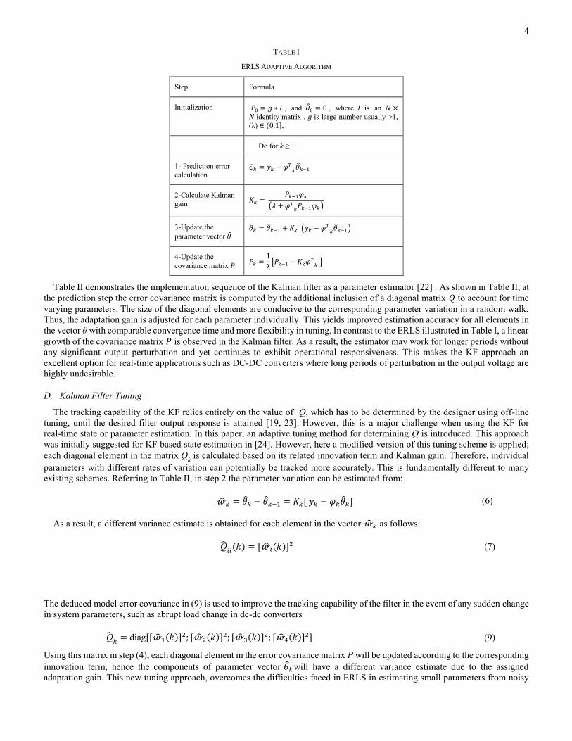
Table II demonstrates the implementation sequence of the Kalman filter as a parameter estimator [22] . As shown in Table II, at
the prediction step the error covariance matrix is computed by the additional inclusion of a diagonal matrix 𝑄 to account for time
varying parameters. The size of the diagonal elements are conducive to the corresponding parameter variation in a random walk.
Thus, the adaptation gain is adjusted for each parameter individually. This yields improved estimation accuracy for all elements in
the vector θ with comparable convergence time and more flexibility in tuning. In contrast to the ERLS illustrated in Table I, a linear
growth of the covariance matrix 𝑃 is observed in the Kalman filter. As a result, the estimator may work for longer periods without
any significant output perturbation and yet continues to exhibit operational responsiveness. This makes the KF approach an
excellent option for real-time applications such as DC-DC converters where long periods of perturbation in the output voltage are
highly undesirable.
D. Kalman Filter Tuning
The tracking capability of the KF relies entirely on the value of Q, which has to be determined by the designer using off-line
tuning, until the desired filter output response is attained [19, 23]. However, this is a major challenge when using the KF for
real-time state or parameter estimation. In this paper, an adaptive tuning method for determining Q is introduced. This approach
was initially suggested for KF based state estimation in [24]. However, here a modified version of this tuning scheme is applied;
each diagonal element in the matrix Qk is calculated based on its related innovation term and Kalman gain. Therefore, individual
parameters with different rates of variation can potentially be tracked more accurately. This is fundamentally different to many
existing schemes. Referring to Table II, in step 2 the parameter variation can be estimated from:
𝑘 = 𝑘 − 𝑘−1 = 𝐾𝑘[ 𝑦𝑘 − 𝜑𝑘𝑘] (6)
As a result, a different variance estimate is obtained for each element in the vector 𝑘 as follows:
Q𝑖𝑖
(𝑘) = [𝑖(𝑘)]2 (7)
The deduced model error covariance in (9) is used to improve the tracking capability of the filter in the event of any sudden change
in system parameters, such as abrupt load change in dc-dc converters
Q𝑘
= diag[[1(𝑘)]2; [2(𝑘)]2; [3(𝑘)]2; [4(𝑘)]2] (9)
Using this matrix in step (4), each diagonal element in the error covariance matrix P will be updated according to the corresponding
innovation term, hence the components of parameter vector 𝑘 will have a different variance estimate due to the assigned
adaptation gain. This new tuning approach, overcomes the difficulties faced in ERLS in estimating small parameters from noisy

5
real time data. Therefore, the estimation accuracy and the tracking performance can be improved significantly for all transfer
function coefficients. Simulation Results
TABLE II
KF CONFIGURED FOR PARAMETER ESTIMATION
Step Formula
Initialization
𝑃(0) = 𝑔 ∗ 𝐼, and 𝜃(0) = 0, where 𝐼 is an
N×N identity matrix, 𝑔 is large number , 𝑟 is
scaler > 0, Q is diag [Q11
, Q22
,..,QNN
]
Do for 𝑘 ≥ 1
`1-Kalman gain 𝐾𝑘 = 𝑃𝑘−1+ 𝜑𝑘
𝑇[𝜑𝑘𝑃𝑘−1+ 𝜑𝑘
𝑇 + 𝑟𝑘]−1
2-Parameters estimate 𝜃𝑘 = 𝜃𝑘−1 + 𝐾𝑘[ 𝑦𝑘 − 𝜑𝑘𝜃𝑘−1]
3-Estimate dispersion
update 𝑃𝑘 = 𝑃𝑘−1
+ (𝐼 − 𝐾𝑘𝜑𝑘)
4-Covariance matrix
project ahead 𝑃𝑘
+ = 𝑃𝑘 + Q
III. SIMULATION RESULTS
In order to verify the performance of the proposed identification algorithm, a voltage controlled synchronous DC–DC buck
SMPC circuit is implemented in MATLAB/Simulink. The component values for the converter depicted in Fig. 1 are: Vin =10 V, RO
= 5 Ω, L= 220 μH, C=330 μF, RC =25 mΩ, RL = 63mΩ, RDS(on)= 18 mΩ, the switching frequency and sampling rate are 20 kHz, and
the sensing gain is 0.5. The output voltage is regulated at 3.3V using digital PID controller (10), designed based on pole placement
technique.
𝐺𝐶(𝑧) =
4.672 − 7.539 𝑧−1 + 3.184 𝑧−2
(1 − 𝑧−1)(1 + 0.374 𝑧−1)
(8)
In the early stages of the estimation process, no preliminary knowledge of the converter parameters is assumed. The same initial
values of covariance matrix and parameter vector for both ERLS and KF are selected to be P(0) = 10000 I, and (0) = 0. A 9 bit
PRBS signal (a rich frequency excitation signal) is injected into the control signal to enhance the parameter estimation
performance. To justify the identification results, the discrete transfer function of the average model in (11) is calculated in
advance, at a sampling time of 50 μs. In line with many other sources of literature, convergence time and accuracy are considered
to be the important metrics in evaluating the adaptive algorithm performance [2, 4].
𝐺𝑣𝑑 =
0.2262 + 0.1119 𝑧−2
1 − 1.913 𝑧−1 + 0.946 𝑧−2
(9)
For the ERLS, the forgetting factor λ= 0.95 is carefully chosen to facilitate a compromise between estimator sensitivity and
convergence speed. Unlike the preliminarily simulation results presented by the authors in [19], the modified tuning method in (9)
is adopted in this paper to mitigate the disadvantages of using a trial and error procedure in the KF tuning and the measurement
noise variance r is set to 0.095. Fig. 2 shows the parameter estimation results obtained using the ERLS identification algorithm and
KF identification algorithm during the steady state operation. As depicted in Fig. 2, both estimation algorithms rapidly identify the
transfer function coefficients with final estimation values very close to the average model in (11). However, the KF estimation
convergence to steady state is less than 0.5 ms, while the ERLS estimator takes around 1.5 ms to converge to the final values.

6
Fig. 2. On-line parameter estimation results using ERLS and KF. (a) Denominator coefficients. (b) Numerator coefficients.
To further evaluate the performance of the propsed KF algorithm, a sudden and significant load change is applied at 0.02 s. The
simulation results, illustrated in Fig.3, indicate that after a sudden change in the load the KF identifies the transfer function
denominator coefficients accurately with a convergence time less than 1 ms. In contrast, the ERLS estimation exhibits under/over
shoot before it settles to the final values with a convergence time more than 5 ms. The stability of both identification algorithms is
evaluated during the absence of the PRBS signal. The estimation results, shown in Fig. 4, demonstrate that the KF estimator has the
ability to produce a smooth and stable estimation with no effect of the estimator wind up. In contrast, the ERLS suffers from
estimator the wind up phenomenon as the adaptation gain value increases over time and yields a clear offset in the final estimation
value.
Fig. 3. On-line parameters estimation during a step load change from 5 Ω to 1 Ω at 0.02s for ERLS and KF
Fig. 4. Estimator win-up effect on ERLS and KF.
IV. EXPERIMENTAL RESULTS
To validate the proposed algorithm, experimental verification is conducted on a 5 W synchronous buck converter. Fig.5 shows the
experimental setup for the proposed real time parameter estimation algorithm. In order to compare the simulation and the
experimental results, the converter parameters are selected to be the same as those outlined in Section III. In addition to the digital
controller described in (10), the entire identification process including PRBS generation, filtering, and the adaptive algorithm is
performed online on a Texas Instruments TMS320F28335 digital signal processor (DSP) platform to validate the proposed
structure in real-time. This is accomplished using the Embedded Coder Support package in MATLAB/Simulink to generate C code
for all related blocks in the Simulink model and to run this model in ‘External Mode’. This feature enables the user to tune and
monitor the algorithm parameters in real time without stopping the application. The obtained real-time results are transferred to
Simulink via a RS232 communication interface as shown in Fig.5. To demonstrate the previously explained advantages of the KF
over the ERLS algorithm, the identification process is enabled for 20 ms, while the PRBS signal is injected into the duty cycle for
10ms only as depicted in Fig.6. A small amplitude signal is selected for the excitation signal to keep the perturbation within 5% of
the nominal output voltage during the identification procedure; it then reverts back to normal operation as shown in Fig.6. Before
real-time implementation, the proposed algorithm is tested off-line to investigate the suitability of the data being used, the selected
model structure, and the filter type. The logged output voltage and the control signal are both sampled at 20 kHz and exported to

7
MATLAB. To accomplish a good estimation result, the measured output voltage and the control signal must be filtered before
being applied to the estimation algorithm.
Parameter Estimation Algorithm
MA
Filter
Gate
Drivers
L
C
RL
Iin
iL
iOiC
RC ROvout(t)
SW1SW2
R1
R2
A/D
vout[k]
Vref [k]
e[k]PIDDPWM
PRBS
MA
Filter
SCI A
d [k]
TMS320F28335
ENABLE
ID
RS232
MATLAB/
SIMULINK /
EXTERNAL
MODE
Vin
(a)
(b)
Fig. 5. Experimental setup of a synchronous buck converter for rea-time parameter estimation. (a) Block diagram (b) Overview of test board.
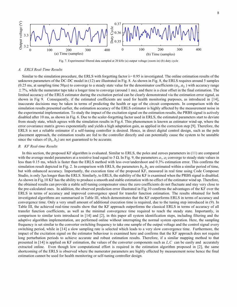
The filtering step is performed using a simple four tap Moving Average (MA) filter. These filtered signals are illustrated in Fig.7.
In the filtered output voltage (Fig.7.a), the ripple content due to the excitation signal is approximately ±2.5% with respect to the
nominal dc output voltage. The achieved offline estimation results confirm that the presented model structure in (3) is suitable to
describe the dynamics of the converter. Furthermore, the simple four-tap MA filter is sufficient to carry out the filtering task for a
successful parameter estimation process. Due to space limitations, only real-time results are presented here as they are of primary
importance.
Fig. 6. Experimental output voltage during identification process with PRBS signal disabled after 10ms.
DSP
PRBS perturbation
Synchronous
buck
converter
ID enabled
8
Fig. 7. Experimental filtered data sampled at 20 kHz (a) output voltage (zoom-in) (b) duty cycle
A. ERLS Real-Time Results
Similar to the simulation procedure, the ERLS with forgetting factor λ= 0.95 is investigated. The online estimation results of the
unknown parameters of the DC-DC model in (12) are illustrated in Fig. 8. As shown in Fig. 8, the ERLS requires around 5 samples
(0.25 ms, at sampling time 50µs) to converge to a steady state value for the denominator coefficients (𝑎1, 𝑎2 ) with accuracy range
±7%, while the numerator taps take a longer time to converge (around 1 ms), and there is a clear offset in the final estimation. The
limited accuracy of the ERLS estimator during the excitation period can be clearly demonstrated via the estimation error signal, as
shown in Fig 9. Consequently, if the estimated coefficients are used for health monitoring purposes, as introduced in [14],
inaccurate decisions may be taken in terms of predicting the health or age of the circuit components. In comparison with the
simulation results presented earlier, the estimation accuracy of the ERLS estimator is highly affected by the measurement noise in
the experimental implementation. To study the impact of the excitation signal on the estimation results, the PRBS signal is actively
disabled after 10 ms, as shown in Fig. 6. Due to the scaler-forgetting factor used in ERLS, the estimated parameters start to deviate
from steady state, which agrees with the simulation results in Fig.4. This phenomenon is known as estimator wind-up, where the
error covariance matrix grows exponentially and yields a high adaptation gain, as applied in the correction step [9]. Therefore, the
ERLS is not a reliable estimator if a self-tuning controller is desired. Hence, in direct digital control design, such as the pole
placement approach, the estimation results are fed to the controller directly and can potentially cause the system to be unstable
since the values of (𝑏1, 𝑏2) are not guaranteed to be accurate.
B. KF Real-time Results
In this section, the proposed KF algorithm is evaluated. Similar to ERLS, the poles and zeroes parameters in (11) are compared
with the average model parameters at a resistive load equal to 5 Ω. In Fig. 9, the parameters a1, a2 converge to steady state values in
less than 0.15 ms, which is faster than the ERLS method with less over/undershoot and 0.3% estimation error. This confirms the
simulation result depicted in Fig. 2. In comparison with ERLS, the parameters 𝑏1, 𝑏2 are estimated within a similar period of time,
but with enhanced accuracy. Importantly, the execution time of the proposed KF, measured in real time using Code Composer
Studio, is only 3μs longer than the ERLS. Similarly, to ERLS, the stability of the KF is examined when the PRBS signal is disabled.
As shown in Fig.10 KF has the ability to produce a smooth and stable estimation with no effect of the estimator wind up. Therefore,
the obtained results can provide a stable self-tuning compensator since the zero coefficients do not fluctuate and stay very close to
the pre-calculated ones. In addition, the observed prediction error illustrated in Fig.10 confirms the advantages of the KF over the
ERLS in terms of accuracy and improved convergence speed for transfer function estimation. The results obtained for both
investigated algorithms are summarised in Table III, which demonstrates that the KF outperforms ERLS in terms of accuracy and
convergence time. Only a very small amount of additional execution time is required, due to the tuning step introduced in (9). In
Table III, the achieved real-time results show that the KF approach outperforms the classical ERLS in terms of accuracy of all
transfer function coefficients, as well as the minimal convergence time required to reach the steady state. Importantly, in
comparison to similar tests introduced in [14] and [2], in this paper all system identification steps, including filtering and the
adaptive algorithm implementation, are performed online without interrupting the normal system operation. Here, the sampling
frequency is set similar to the converter switching frequency to take one sample of the output voltage and the control signal every
switching period, while in [14] a slow sampling rate is selected which leads to a very slow convergence time. Furthermore, the
impact of the excitation signal on the estimator behaviour is examined here and confirms that the KF approach does not require
long perturbation periods to achieve accurate and robust estimation results. Therefore, if a similar mapping method to that
presented in [14] is applied on KF estimation, the values of the converter components such as L,C can be easily and accurately
extracted online. Even though low computational effort is required in the estimation algorithm proposed in [2], the same
shortcoming of the ERLS is observed where the numerator parameters are highly effected by measurement noise hence the final
estimation cannot be used for health monitoring or self-tuning controller design.

9
Fig. 8. The estimation results using ERLS with λ=0.95. (a) Denominator coefficients. (b) Numerator coefficients.
Fig. 9. The estimation error for ERLS during steady state operation. (a) Denominator coefficients. (b) Numerator coefficients.
Fig. 10. The estimation results using KF. (a) Denominator coefficients. (b) Numerator coefficients.
Fig. 11. The estimation error for KF during steady state operation. (a) Denominator coefficients. (b) Numerator coefficients

10
C. Parameter Estimation During Abrupt Load Change
In SMPC it is well recognised that the mode of operation can potentially be diverted from continuous conducting mode (CCM) to
discontinuous conducting (DCM) if a wide load variation is applied, as a result loop stability margins are decreased and the
converter may exhibit instability upon the mode transition [25]. Traditionally, this phenomenon is treated by designing a
conservative controller (effectively a worst-case design) to cope with any abrupt changes and ensure the system stability.
Fig. 12. Output voltage recorded on the DSP during a step load change from 5 Ω to 1 Ω at 0.015 s
Therefore, it is a great benefit if the load value is estimated and the controller is tuned to meet the desired bandwidth and stability
margins. For this reason, a wide and abrupt load change is applied to further investigate the performance of the proposed self-tuned
KF. Fig.12 shows the dynamic response of the output voltage when the load is changed from 5 Ω to 1 Ω at 0.015 s. As previously
confirmed, the KF provide excellent estimation performance without any perturbation in the observed data. This can be seen
clearly in the recorded output voltage in Fig.12, where no excitation signal is injected. This scenario is deliberately applied,
because in the case of ERLS the estimated parameters deviate immediately once the PRBS is disabled, so if the load changes after
this instant the ERLS is unable to detect the new variation and another perturbation period is required to perform the estimation
process. Therefore, a PRBS signal is injected before the step change applied to investigate the performance of ERLS during load
variation. On the other hand, the KF estimator stays alert to the situation for a longer period, hence no perturbation is required to
detect the load change. Fig.13 (a), shows the KF estimation results, with the transfer function poles accurately estimated before and
after the load change with convergence time less than 1ms. In contrast, the ERLS estimation has a clear offset during steady state,
which improves after the load change as illustrated in Fig.13 (b). This behaviour confirms that the ERLS estimator requires a large
perturbation signal to provide accurate and reliable estimation. It is worth noting that, the numerator parameters are not illustrated
here due to the small effect of the load change that can be ignored according to the computed transfer function (12).
𝐺𝑣𝑑 =
0.2243 𝑧−1 + 0.1062 𝑧−2
1 − 1.814 𝑧−1 + 0.8437 𝑧−2 (10)
To demonstrate the advantages of using the proposed tuning method, the related adaptation gains of a1 and a2 are recorded in steady
state and during the load change as illustrated in Fig.14 (a). As stated in (11), each element in the matrix Q is tuned accordingly to
the contribution of the related parameter vector component in the estimator output (𝜑𝑘𝑘). Therefore, the assigned Kalman gain
elements for K1 for a1, and K2 for a2, vary with different rates in the correction step. This yields improved overall tracking
performance to the newly applied load. This variation is confirmed by referring to (12) and (13), where parameter a1 decreases by
5.5% and a2 simultaneously decreases by 1% when the load abruptly reduces from 5Ω to 1 Ω. Therefore, the impact of load change
varies between one coefficient and another in the discrete transfer function. In contrast, the ERLS algorithm react to the load
change by applying similar magnitude with different directions for both a1 and a2 in the correction step, due to the single forgetting
factor scheme as shown in Fig.14 (b). Thus, the KF approach is considered to be the ideal candidate in this case to provide reliable
estimation for time varying parameters; such as load change which is a common scenario in power converter applications.

11
Fig. 13. Real-time parameters estimation during a step load change from 5 Ω to 1 Ω at 0.015s, (a) KF, (b) ERLS
Fig. 14. Kalman Gains, (a) KF, (b) ERLS.
V. CONCLUSION
This paper presents a new real-time parameter estimation technique for DC-DC converter systems, based on a self-tuned Kalman
Filter approach. The proposed technique has the potential for use in real time system identification and adaptive control systems for
power electronic applications, such as switch mode power supplies. The mathematical description of the proposed algorithm is
presented, and the algorithm is fully validated using a digitally controlled buck power converter. In this paper, unlike a significant
proportion of existing literature, the entire system identification and closed loop control process is seamlessly implemented in
real-time hardware, without any remote intermediate post processing analysis. Experimental results show that the proposed
Kalman Filter provides accurate and fast estimation of the discrete transfer function. The performance of the Kalman filter is also
tested without a perturbation signal, and the results obtained prove that the covariance matrix update scheme keeps the estimator
stable and responsive for longer periods of time. Furthermore, and important from a practical perspective, the effect of estimator
wind up is reduced. Additionally, a new state-of-the-art tuning method for the process covariance matrix has been introduced to
optimise convergence speed and allow the estimator to track time varying parameters. The advantage of this has been successfully
validated via an abrupt step change in load.

12
REFERENCES
[1] H. Renaudineau, J. P. Martin, M. B. Nahid and S. Pierfederici, "DC-DC converters dynamic modeling with state observer-based parameter estimation", IEEE
Trans. Power Electron., vol. 30, no. 6, pp. 3356-3363, Jun. 2015.
[2] M. Algreer, M. Armstrong and D. Giaouris, "Active online system identification of switch mode DC-DC power converter based on efficient recursive
DCD-IIR adaptive filter", IEEE Trans. Power Electron., vol. 27, no. 11, pp. 4425-4435, Jun. 2012.
[3] R.-J. Wai, Y.-F. Lin and Y.-K. Liu, "Design of adaptive fuzzy-neural-network control for single-stage boost inverter", IEEE Trans. Power Electron., vol. 30,
no. 12, pp. 7282-7298, Dec. 2015.
[4] G. E. Pitel and P. T. Krein, "Real-time system identification for load monitoring and transient handling of DC–DC supplies", Proc. IEEE Power Electron. Spec. Conf., pp. 3807-3813.
[5] M. M. Peretz and S. Ben-Yaakov, "Time-domain identification of pulse-width modulated converters," IET Power Electron, vol. 5, pp. 166-172, 2012.
[6] M. Bhardwaj, S. Choudhury, R. Poley, and B. Akin, "Online Frequency Response Analysis: A Powerful Plug-in Tool for Compensation Design and Health Assesment of Digitally Controlled Power Converters," IEEE Trans. Ind. Appl., vol. PP, pp. 1-1, 2016.
[7] L. Jun-Yan, Y. Chun-Hung, and T. Chien-Hung, "Correlation-based system identification of digitally controlled SMPS," in Power Electronics and Drive
Systems (PEDS), 2011 IEEE Ninth International Conference on, 2011, pp. 1149-1152.
[8] A. Barkely and E. Santi, "Improved online identification of a DC–DC converter and its control loop gain using cross- correlation methods", IEEE Trans.
Power Electron., vol. 24, no. 8, pp. 2021-2031, Aug. 2009.
[9] L. Ljung, System Identification: Theory for the User, 2nd ed. Upper Saddle River, NJ: Prentice-Hall, 1999.
[10] B. Johansson and M. Lenells, “Possibilities of obtaining small-signalmodels of dc–dc power converters by means of system identification,” in Proc.
Telecommun. Energy Conf., 2000, pp. 65–75.
[11] M. Shirazi, J. Morroni, A. Dolgov, R. Zane and D. Maksimovic, "Integration of frequency response measurement capabilities in digital controllers for DC–DC converters", IEEE Trans. Power Electron., vol. 23, no. 5, pp. 2524-2535, Sep. 2008.
[12] J. Castello and J. M. Espi, "DSP implementation for measuring the loop gain frequency response of digitally controlled power converters", IEEE Trans. Power
Electron., vol. 27, no. 9, pp. 4113-4121, Sep. 2012.
[13] F. Alonge, F. D’Ippolito, F. M. Raimondi and S. Tumminaro, "Nonlinear modelling of DC/DC converters using the Hammerstein's approach", IEEE Trans.
Power Electron., vol. 22, no. 4, pp. 1210-1221, Jul. 2007.
[14] B. X. Li and K. S. Low, "Low Sampling Rate Online Parameters Monitoring of DC-DC Converters for Predictive-Maintenance Using Biogeography-Based Optimization," IEEE Trans. Power Electron., vol. 31, pp. 2870-2879, 2016.
[15] M. Algreer, M. Armstrong and D. Giaouris, "System identification of PWM DC–DC converters during abrupt load changes", Proc. IEEE Ind. Electron. Conf.,
pp. 1788-1793.
[16] A. Vahidi, A. Stefanopoulou, and H. Peng, "Recursive least squares with forgetting for online estimation of vehicle mass and road grade: theory and
experiments," Vehicle System Dynamics, vol. 43, pp. 31-55, 2005.
[17] L. Corradini, D. Maksimovic, P. Mattavelli, and R. Zane, "Continuous-Time Averaged Modeling of DC-DC Converters," in Digital Control of High-Frequency Switched-Mode Power Converters, ed: Wiley-IEEE Press, 2015, pp. 1-360.
[18] R. Redl and J. Sun, "Ripple-based control of switching regulators: An overview", IEEE Trans. Power Electron., vol. 24, no. 12, pp. 2669-2680, Dec. 2009.
[19] M. Ahmeid, M. Armstrong, S. Gadoue, and P. Missailidis, "Parameter estimation of a DC-DC converter using a Kalman Filter approach," in Proc. IET Int. Conf. PEMD, 2014, pp. 1–6.
[20] M. A. Eleffendi and C. M. Johnson, "Application of Kalman Filter to Estimate Junction Temperature in IGBT Power Modules," IEEE Trans. Power Electron.,
vol. 31, pp. 1576-1587, 2016.
[21] O. Rosen and A. Medvedev, "Efficient parallel implementation of a Kalman filter for single output systems on multicore computational platforms," in 2011
50th IEEE Conference on Decision and Control and European Control Conference, 2011, pp. 3178-3183.
[22] L. Cao and H. M. Schwartz, "Analysis of the Kalman filter based estimation algorithm: an orthogonal decomposition approach," Automatica, vol. 40, pp. 5-19, 2004.
[23] G. Welch and G. Bishop, "An introduction to the kalman filter. Department of Computer Science, University of North Carolina," ed: Chapel Hill, NC,
unpublished manuscript, 2006.
[24] J. A. R. Macias and A. Gomez-Exposito, "Self-tuning of Kalman filters for digital protection applications," in Power Tech, 2005 IEEE Russia, 2005, pp. 1-4.
[25] J. Morroni, L. Corradini, R. Zane and D. Maksimovic, "Adaptive tuning of switched-mode power supplies operating in discontinuous and continuous
conduction modes", IEEE Trans. Power Electron., vol. 24, no. 11, pp. 2603-2611, Nov. 2009.
Mohamed Ahmeid received the B.Sc. degree in automatic control from College of Electronic Technology, Bani Walid, Libya in 2003, the M.Sc. degree in
automation and control from Newcastle University, Newcastle Upon Tyne, U.K. in 2010. From 2005 to 2008 and from 2010 to 2012, he was a senior commissioning engineer with the General Electricity Company of Libya (GECOL). He is currently working toward the Ph.D. degree in electrical and electronic
engineering at Newcastle University, Newcastle Upon Tyne, U.K. His research interests include system identification real-time digital control of power electronic converters, adaptive filtering, autonomous ground vehicle control using artificial intelligent methods.

13
Matthew Armstrong received the M.Eng. and Ph.D. degrees from Newcastle University, Newcastle Upon Tyne, U.K. in 1998 and 2007, respectively. He is
currently a Lecturer in control of electrical power at Newcastle University. Prior to his university lectureship, he spent eight years as a Research Associate with the Newcastle University Power Electronics, Drives and Machines Group. His current research interests include real-time digital control of power electronic converters
and electrical drive systems, advanced control of grid connected renewable energy systems, and hardware-in-the-loop emulation systems.
Shady Gadoue received the B.Sc. and M.Sc. degrees from Alexandria University, Alexandria, Egypt, in 2000 and 2003, respectively, and the Ph.D. degree from Newcastle University, Newcastle upon Tyne, U.K., in 2009, all in electrical engineering. From 2009 to 2011, he was an Assistant Professor with the Department of
Electrical Engineering, Alexandria University, where he was an Assistant Lecturer from 2000 to 2005. In 2011, he joined the Electrical Power Research Group,
Newcastle University, as a Lecturer in Control Systems. Since March 2016, Dr Gadoue has been a visiting member of academic staff with the Control and Power Research Group at Imperial College London, U.K. His main research interests include control, state and parameter identification, and optimization algorithms
applied to energy conversion and power electronic systems.
Maher Algreer received the B.Sc. degree in electronic and communication engineering and theM.Sc. degree in computer engineering from Mosul University, Mosul, Iraq, in 1999 and 2005, respectively, where he specialized in the field of digital selftuning PID controllers using fuzzy logic controller. He is currently
working toward the Ph.D. degree in electrical, electronic, and computer engineering at Newcastle University, Newcastle Upon Tyne, U.K. His research interests
include embedded controls, adaptive digital control, fuzzy logic, signal processing, system identification, and power electronic control design
Petros Missailidis received the B.S degree in mechanical engineering from Aristotelian University of Thessaloniki, Thessaloniki, Greece, in 1986, the M.S. degree
in mechanical engineering from the University of Buffalo, NY, USA, in 1990, the M.S. degrees in electrical and electronic engineering and biomedical engineering
from Rensselaer Polytechnic Institute, Troy, NY, in 1993, the M.S. degree in mechanical engineering from the same institute in 1995, and the Ph.D. degree in mechanical engineering from Rensselaer Polytechnic Institute, in 2000. He was with ComHouse Wireless Inc., M/A-COM Inc., General Electric Schenectady NY,
Erie County Medical Centre, Buffalo, NY, and the University of Toronto. He is currently with the School of Electrical and Electronics Engineering, Newcastle
University, Newcastle upon Tyne, UK, where he is involved in conducting research in the areas of system identification, nonlinear control, and control of electric drives.


![8408-11 EC International Prospectus V5[Single Pages]](https://static.fdocuments.us/doc/165x107/577ce6df1a28abf10393d124/8408-11-ec-international-prospectus-v5single-pages.jpg)

