IEEE TRANSACTIONS ON POWER DELIVERY, VOL. … · Bolted Connectors for Stranded Aluminum Power...
8
IEEE TRANSACTIONS ON POWER DELIVERY, VOL. 23, NO. 2, APRIL 2008 523 Bolted Connectors for Stranded Aluminum Power Conductors Magne Runde, Niklas Magnusson, and Atle Lenes Abstract—Sixteen different commercial bolted connectors for 50 and 240 mm stranded aluminum cable conductors have been examined in order to identify and clarify the correlations between the quality of a connector and its design characteristics, material usage, assembly procedures, bolt numbers and configurations and other relevant parameters. The quality is assessed with basis in resistance measurements after short circuit testing and during thermal cycling as specified by the IEC 61238-1 standard. The tightening torque of the bolts was measured during connector as- sembly, and the resulting axial compressive forces were calculated. A very strong correlation is observed between this compressive force and the connector quality; large forces give connections with low and stables resistances. The various other design parameters considered are found to have significantly less or in some cases hardly any notable influence on the electrical test results. Index Terms—Aluminum power conductors, connectors, contact mechanical factors, contact resistance, power cable connecting, testing. I. INTRODUCTION A LARGE number of connector types for splicing under- ground power cable conductors are available. Among the most widely used ones are compression or crimping connectors and bolted connectors. In both these types the conductors to be joined are fed into a hollow cylinder or tube, usually referred to as the barrel or sleeve. The generic difference lies in whether the conductor ends are secured by mechanically compressing and deforming the barrel, or by tightening bolts going through the barrel wall. The first category typically involves hydraulic or mechanical tools that make one or more indents or compressions forming the barrel to a predetermined shape. The tool provides what forces may be necessary, so in this case the barrel deformation is al- ways the same, unaffected by conductor properties such as hard- ness and number of strands. In bolted connectors, on the other hand, the bolt torque is the constant and predetermined factor. Hence, in connectors of this category the mechanical force exerted on the conductor by the bolts is constant, and the conductor deformation varies with the conductor properties. Bolted connectors have in recent years become increasingly popular for joining conductors of insulated cables used for power distribution and transmission. The prime reason is that bolted connectors in most cases are easier to assemble than Manuscript received April 30, 2007. Paper no. TPWRD-00237-2007. The authors are with SINTEF Energy Research, Trondheim 7465, Norway (e-mail: [email protected]; [email protected]; [email protected]). Digital Object Identifier 10.1109/TPWRD.2007.916101 Fig. 1. The 50 mm connectors examined. Fig. 2. The 240 mm connectors examined. compression connectors, at least for larger cross sections. Usually, only a socket wrench is required, as opposed to the bulky hydraulic or electrical compression tools needed for most compression connectors. The connectors constitute only a very small part of the total costs of a power cable system, but failing connectors often lead to power outages and costly repairs. Assuring that connectors operate with a low and stable contact resistance over their en- tire life time is thus of crucial importance, but not necessarily an easy task. In particular, the well known difficulties associ- ated with using aluminum as a contact material have to be taken carefully into consideration when designing connectors for use on aluminum conductors [1]. In Europe the IEC 61238-1 standard [2] is widely used for testing of power connectors. It prescribes 1000 heat cycles and six short circuit tests. To pass the connectors have to meet a number of requirements related to resistance and temperature. In a previous study [3] the quality of a wide variety of com- pression connectors for stranded 240 mm aluminum conduc- 0885-8977/$25.00 © 2008 IEEE
-
Upload
phungtuong -
Category
Documents
-
view
217 -
download
1
Transcript of IEEE TRANSACTIONS ON POWER DELIVERY, VOL. … · Bolted Connectors for Stranded Aluminum Power...
IEEE TRANSACTIONS ON POWER DELIVERY, VOL. 23, NO. 2, APRIL 2008 523
Bolted Connectors for StrandedAluminum Power Conductors
Magne Runde, Niklas Magnusson, and Atle Lenes
Abstract—Sixteen different commercial bolted connectors for50 and 240 mm� stranded aluminum cable conductors have beenexamined in order to identify and clarify the correlations betweenthe quality of a connector and its design characteristics, materialusage, assembly procedures, bolt numbers and configurations andother relevant parameters. The quality is assessed with basis inresistance measurements after short circuit testing and duringthermal cycling as specified by the IEC 61238-1 standard. Thetightening torque of the bolts was measured during connector as-sembly, and the resulting axial compressive forces were calculated.A very strong correlation is observed between this compressiveforce and the connector quality; large forces give connections withlow and stables resistances. The various other design parametersconsidered are found to have significantly less or in some caseshardly any notable influence on the electrical test results.
Index Terms—Aluminum power conductors, connectors, contactmechanical factors, contact resistance, power cable connecting,testing.
I. INTRODUCTION
ALARGE number of connector types for splicing under-ground power cable conductors are available. Among the
most widely used ones are compression or crimping connectorsand bolted connectors.
In both these types the conductors to be joined are fed intoa hollow cylinder or tube, usually referred to as the barrel orsleeve. The generic difference lies in whether the conductor endsare secured by mechanically compressing and deforming thebarrel, or by tightening bolts going through the barrel wall. Thefirst category typically involves hydraulic or mechanical toolsthat make one or more indents or compressions forming thebarrel to a predetermined shape. The tool provides what forcesmay be necessary, so in this case the barrel deformation is al-ways the same, unaffected by conductor properties such as hard-ness and number of strands.
In bolted connectors, on the other hand, the bolt torque is theconstant and predetermined factor. Hence, in connectors of thiscategory the mechanical force exerted on the conductor by thebolts is constant, and the conductor deformation varies with theconductor properties.
Bolted connectors have in recent years become increasinglypopular for joining conductors of insulated cables used forpower distribution and transmission. The prime reason is thatbolted connectors in most cases are easier to assemble than
Manuscript received April 30, 2007. Paper no. TPWRD-00237-2007.The authors are with SINTEF Energy Research, Trondheim 7465,
Norway (e-mail: [email protected]; [email protected];[email protected]).
Digital Object Identifier 10.1109/TPWRD.2007.916101
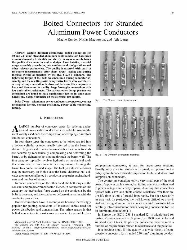
Fig. 1. The 50 mm connectors examined.
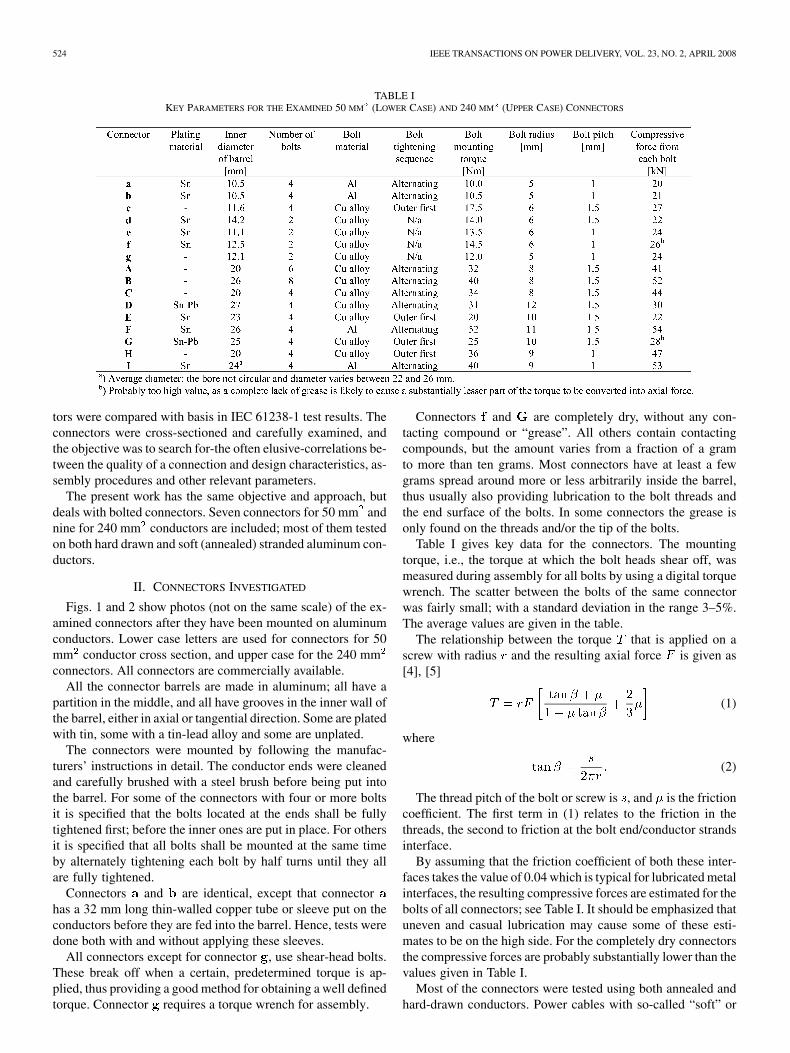
Fig. 2. The 240 mm connectors examined.
compression connectors, at least for larger cross sections.Usually, only a socket wrench is required, as opposed to thebulky hydraulic or electrical compression tools needed for mostcompression connectors.
The connectors constitute only a very small part of the totalcosts of a power cable system, but failing connectors often leadto power outages and costly repairs. Assuring that connectorsoperate with a low and stable contact resistance over their en-tire life time is thus of crucial importance, but not necessarilyan easy task. In particular, the well known difficulties associ-ated with using aluminum as a contact material have to be takencarefully into consideration when designing connectors for useon aluminum conductors [1].
In Europe the IEC 61238-1 standard [2] is widely used fortesting of power connectors. It prescribes 1000 heat cycles andsix short circuit tests. To pass the connectors have to meet anumber of requirements related to resistance and temperature.
In a previous study [3] the quality of a wide variety of com-pression connectors for stranded 240 mm aluminum conduc-
0885-8977/$25.00 © 2008 IEEE
524 IEEE TRANSACTIONS ON POWER DELIVERY, VOL. 23, NO. 2, APRIL 2008
TABLE IKEY PARAMETERS FOR THE EXAMINED 50 MM (LOWER CASE) AND 240 MM (UPPER CASE) CONNECTORS
tors were compared with basis in IEC 61238-1 test results. Theconnectors were cross-sectioned and carefully examined, andthe objective was to search for-the often elusive-correlations be-tween the quality of a connection and design characteristics, as-sembly procedures and other relevant parameters.
The present work has the same objective and approach, butdeals with bolted connectors. Seven connectors for 50 mm andnine for 240 mm conductors are included; most of them testedon both hard drawn and soft (annealed) stranded aluminum con-ductors.
II. CONNECTORS INVESTIGATED
Figs. 1 and 2 show photos (not on the same scale) of the ex-amined connectors after they have been mounted on aluminumconductors. Lower case letters are used for connectors for 50mm conductor cross section, and upper case for the 240 mmconnectors. All connectors are commercially available.
All the connector barrels are made in aluminum; all have apartition in the middle, and all have grooves in the inner wall ofthe barrel, either in axial or tangential direction. Some are platedwith tin, some with a tin-lead alloy and some are unplated.
The connectors were mounted by following the manufac-turers’ instructions in detail. The conductor ends were cleanedand carefully brushed with a steel brush before being put intothe barrel. For some of the connectors with four or more boltsit is specified that the bolts located at the ends shall be fullytightened first; before the inner ones are put in place. For othersit is specified that all bolts shall be mounted at the same timeby alternately tightening each bolt by half turns until they allare fully tightened.
Connectors and are identical, except that connectorhas a 32 mm long thin-walled copper tube or sleeve put on theconductors before they are fed into the barrel. Hence, tests weredone both with and without applying these sleeves.
All connectors except for connector , use shear-head bolts.These break off when a certain, predetermined torque is ap-plied, thus providing a good method for obtaining a well definedtorque. Connector requires a torque wrench for assembly.
Connectors and are completely dry, without any con-tacting compound or “grease”. All others contain contactingcompounds, but the amount varies from a fraction of a gramto more than ten grams. Most connectors have at least a fewgrams spread around more or less arbitrarily inside the barrel,thus usually also providing lubrication to the bolt threads andthe end surface of the bolts. In some connectors the grease isonly found on the threads and/or the tip of the bolts.
Table I gives key data for the connectors. The mountingtorque, i.e., the torque at which the bolt heads shear off, wasmeasured during assembly for all bolts by using a digital torquewrench. The scatter between the bolts of the same connectorwas fairly small; with a standard deviation in the range 3–5%.The average values are given in the table.
The relationship between the torque that is applied on ascrew with radius and the resulting axial force is given as[4], [5]
(1)
where
(2)
The thread pitch of the bolt or screw is , and is the frictioncoefficient. The first term in (1) relates to the friction in thethreads, the second to friction at the bolt end/conductor strandsinterface.
By assuming that the friction coefficient of both these inter-faces takes the value of 0.04 which is typical for lubricated metalinterfaces, the resulting compressive forces are estimated for thebolts of all connectors; see Table I. It should be emphasized thatuneven and casual lubrication may cause some of these esti-mates to be on the high side. For the completely dry connectorsthe compressive forces are probably substantially lower than thevalues given in Table I.
Most of the connectors were tested using both annealed andhard-drawn conductors. Power cables with so-called “soft” or
RUNDE et al.: BOLTED CONNECTORS FOR STRANDED ALUMINUM POWER CONDUCTORS 525
TABLE IICONDUCTOR PROPERTIES
annealed conductors have become increasingly popular amongelectric utilities due to their greater mechanical flexibilitycompared to cables with conventional hard-drawn conductors.Table II lists data for the conductors used in the present inves-tigation.
The tensile strength of all strands of a sample of each con-ductor type was measured, and the lowest and highest valuesare given in the table. The actual cross sections are determinedby weighing a certain conductor length and assuming that itsdensity is as for pure aluminum.
Connector was tested on sector shaped 240 mm conduc-tors even though the 20 mm inner diameter of the barrel makesit necessary to pre-press and substantially deform the conductorto get it into the barrel. This procedure is in compliance withinstructions given by the connector manufacturer.
III. EXPERIMENTAL
Thermal cycling and short circuit currents were applied as de-scribed in the IEC 61238-1 standard [2]: The connectors weremounted in series, and thermally cycled by applying ac. In eachcycle the conductor temperature distant from the connectors iscycled between 35 C and 120–140 C. The short circuit testsare carried out after 200 cycles, by applying a current that in-creases the temperature of the reference part of the conductorfrom 35 C to between 250 and 270 C. The duration of thecurrent should be between 0.9 and 1.5 s. The magnitudes of theshort circuit currents were in the present investigation approxi-mately 6 kA and 23 kA for the 50 mm and 240 mm connec-tors, respectively.
The resistance across each connector is measured before initi-ating the thermal cycling, after 200 cycles (both before and afterthe short circuit test), after 250 cycles and then for every 75 cy-cles until the test is completed after 1000 cycles. In addition, thetemperatures of the connectors and of the reference part of theconductors are continuously logged.
The quality assessments of the various connectors are carriedout with basis in -values. The -value is the ratio between theresistance of a connection and the resistance of a correspondinglength of the conductor. Hence, a splice between two conductorsyielding a -value equal to unity has the same resistance as aconductor without the connector.
According to the IEC 61238-1 standard, six specimens ofeach connection type shall be tested. That is, for each connector/conductor combination six samples or specimens should un-dergo the procedures described above. In this respect the presentinvestigation did not follow the standard; for most of the con-nections only three specimens were tested. This significantly re-duced cost and time consumption, and allowed for more connec-tions to be tested.
The standard prescribes a detailed procedure for determiningfive evaluation parameters; four from the obtained -values andone from the temperature recordings. However, with only threespecimens these procedures can only be partly followed. Twoof the evaluation parameters provide measures on the scatter in
-values among the six specimens and these cannot be deter-mined. The other three parameters, in contrast, operate on singlespecimens and can thus be determined also when the number ofspecimens deviates from six. These are the parameter whichis a measure of the change in the -values of a specimen over thelast 11 measurements (i.e., from cycle no. 250 and onwards), theparameter which is the ratio between the maximum and ini-tial -values of a specimen, and which is the ratio be-tween the maximum temperature of the connector and the tem-perature of the reference part of the conductor.
The maximum acceptable values for the latter two parametersare and . Consequently, if the -value ofa connector more than doubles, or if the connector temperaturebecomes higher than the conductor temperature, the connectorhas failed.
After the IEC 61238-1 test procedures had been completed,samples of all the tested connectors were embedded in epoxyresin and cross-sectioned through the center of the outermostbolt. The cross-sectional surfaces were polished down to amirror finish using silicon carbide paper and diamond paste.This clearly reveals the interior of the connection, includinghow the conductor strands are distributed and deformed.
IV. RESULTS
A. Electrical Test
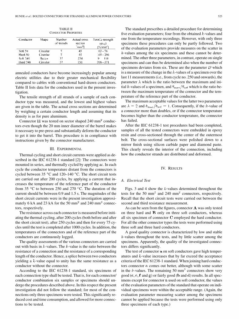
Figs. 3 and 4 show the -values determined throughout thetests for the 50 mm and 240 mm connectors, respectively.Recall that the short circuit tests were carried out between thesecond and third resistance measurement.
As can be seen from the figures, connector was only testedon three hard and only on three soft conductors, whereasall six specimen of connector employed the hard conductor.For all the other connector types the tests were performed usingthree soft and three hard conductors.
A good quality connector is characterized by low and stable-values throughout the tests, and by little scatter among the
specimens. Apparently, the quality of the investigated connec-tors differs significantly.
The test of connector on soft conductors gave high temper-atures and -value increases that by far exceed the acceptancecriteria of the IEC 61238-1 standard. When joining hard conduc-tors connector comes out better, although with some scatterin the -values. The remaining 50 mm connectors show verygood ( and ) or fairly good ( and ) results. In all spec-imens except for connector used on soft conductor, the valuesof the evaluation parameters of the standard that operate on indi-vidual specimens were within the acceptable range. (Again, theevaluation parameter measuring scatter among the specimenscannot be applied because the tests were performed using onlythree specimens of each type.)
526 IEEE TRANSACTIONS ON POWER DELIVERY, VOL. 23, NO. 2, APRIL 2008
Fig. 3. Measured k-values from testing the 50 mm connectors on hard � � and soft � � conductors.
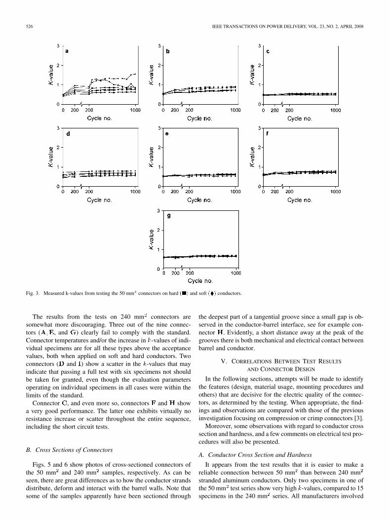
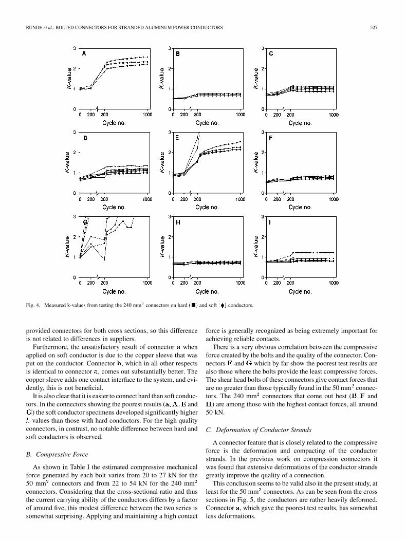
The results from the tests on 240 mm connectors aresomewhat more discouraging. Three out of the nine connec-tors ( , and ) clearly fail to comply with the standard.Connector temperatures and/or the increase in -values of indi-vidual specimens are for all these types above the acceptancevalues, both when applied on soft and hard conductors. Twoconnectors ( and ) show a scatter in the -values that mayindicate that passing a full test with six specimens not shouldbe taken for granted, even though the evaluation parametersoperating on individual specimens in all cases were within thelimits of the standard.
Connector , and even more so, connectors and showa very good performance. The latter one exhibits virtually noresistance increase or scatter throughout the entire sequence,including the short circuit tests.
B. Cross Sections of Connectors
Figs. 5 and 6 show photos of cross-sectioned connectors ofthe 50 mm and 240 mm samples, respectively. As can beseen, there are great differences as to how the conductor strandsdistribute, deform and interact with the barrel walls. Note thatsome of the samples apparently have been sectioned through
the deepest part of a tangential groove since a small gap is ob-served in the conductor-barrel interface, see for example con-nector . Evidently, a short distance away at the peak of thegrooves there is both mechanical and electrical contact betweenbarrel and conductor.
V. CORRELATIONS BETWEEN TEST RESULTS
AND CONNECTOR DESIGN
In the following sections, attempts will be made to identifythe features (design, material usage, mounting procedures andothers) that are decisive for the electric quality of the connec-tors, as determined by the testing. When appropriate, the find-ings and observations are compared with those of the previousinvestigation focusing on compression or crimp connectors [3].
Moreover, some observations with regard to conductor crosssection and hardness, and a few comments on electrical test pro-cedures will also be presented.
A. Conductor Cross Section and Hardness
It appears from the test results that it is easier to make areliable connection between 50 mm than between 240 mmstranded aluminum conductors. Only two specimens in one ofthe 50 mm test series show very high -values, compared to 15specimens in the 240 mm series. All manufacturers involved
RUNDE et al.: BOLTED CONNECTORS FOR STRANDED ALUMINUM POWER CONDUCTORS 527
Fig. 4. Measured k-values from testing the 240 mm connectors on hard � � and soft � � conductors.
provided connectors for both cross sections, so this differenceis not related to differences in suppliers.
Furthermore, the unsatisfactory result of connector whenapplied on soft conductor is due to the copper sleeve that wasput on the conductor. Connector , which in all other respectsis identical to connector , comes out substantially better. Thecopper sleeve adds one contact interface to the system, and evi-dently, this is not beneficial.
It is also clear that it is easier to connect hard than soft conduc-tors. In the connectors showing the poorest results ( and
) the soft conductor specimens developed significantly higher-values than those with hard conductors. For the high quality
connectors, in contrast, no notable difference between hard andsoft conductors is observed.
B. Compressive Force
As shown in Table I the estimated compressive mechanicalforce generated by each bolt varies from 20 to 27 kN for the50 mm connectors and from 22 to 54 kN for the 240 mmconnectors. Considering that the cross-sectional ratio and thusthe current carrying ability of the conductors differs by a factorof around five, this modest difference between the two series issomewhat surprising. Applying and maintaining a high contact
force is generally recognized as being extremely important forachieving reliable contacts.
There is a very obvious correlation between the compressiveforce created by the bolts and the quality of the connector. Con-nectors and which by far show the poorest test results arealso those where the bolts provide the least compressive forces.The shear head bolts of these connectors give contact forces thatare no greater than those typically found in the 50 mm connec-tors. The 240 mm connectors that come out best ( and
) are among those with the highest contact forces, all around50 kN.
C. Deformation of Conductor Strands
A connector feature that is closely related to the compressiveforce is the deformation and compacting of the conductorstrands. In the previous work on compression connectors itwas found that extensive deformations of the conductor strandsgreatly improve the quality of a connection.
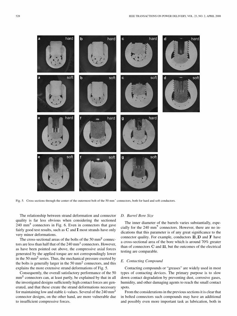
This conclusion seems to be valid also in the present study, atleast for the 50 mm connectors. As can be seen from the crosssections in Fig. 5, the conductors are rather heavily deformed.Connector , which gave the poorest test results, has somewhatless deformations.
528 IEEE TRANSACTIONS ON POWER DELIVERY, VOL. 23, NO. 2, APRIL 2008
Fig. 5. Cross sections through the center of the outermost bolt of the 50 mm connectors, both for hard and soft conductors.
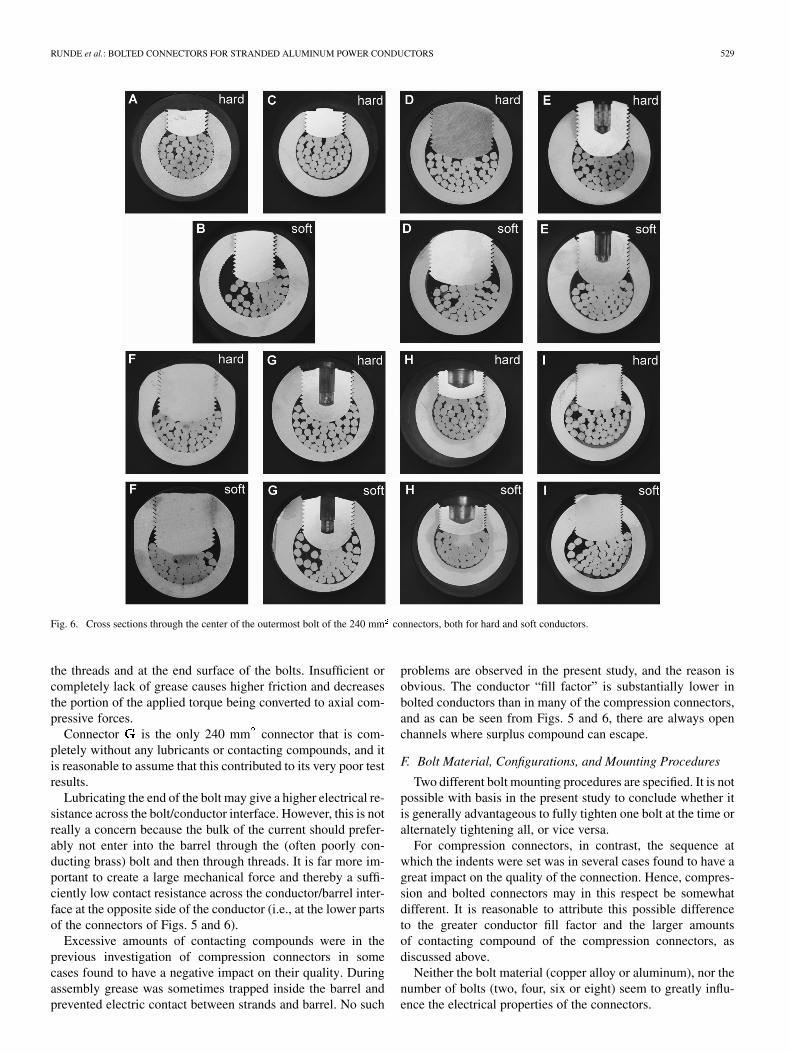
The relationship between strand deformation and connectorquality is far less obvious when considering the sectioned240 mm connectors in Fig. 6. Even in connectors that gavefairly good test results, such as and most strands have onlyvery minor deformations.
The cross-sectional areas of the bolts of the 50 mm connec-tors are less than half that of the 240 mm connectors. However,as have been pointed out above, the compressive axial forcesgenerated by the applied torque are not correspondingly lowerin the 50 mm series. Thus, the mechanical pressure exerted bythe bolts is generally larger in the 50 mm connectors, and thisexplains the more extensive strand deformations of Fig. 5.
Consequently, the overall satisfactory performance of the 50mm connectors can, at least partly, be explained by that in allthe investigated designs sufficiently high contact forces are gen-erated, and that these create the strand deformations necessaryfor maintaining low and stable -values. Several of the 240 mmconnector designs, on the other hand, are more vulnerable dueto insufficient compressive forces.
D. Barrel Bore Size
The inner diameter of the barrels varies substantially, espe-cially for the 240 mm connectors. However, there are no in-dications that this parameter is of any great significance to theconnector quality. For example, conductors and havea cross-sectional area of the bore which is around 70% greaterthan of connectors and , but the outcomes of the electricaltesting are comparable.
E. Contacting Compound
Contacting compounds or “greases” are widely used in mosttypes of contacting devices. The primary purpose is to slowdown contact degradation by preventing dust, corrosive gases,humidity, and other damaging agents to reach the small contactspots.
From the considerations in the previous sections it is clear thatin bolted connectors such compounds may have an additionaland possibly even more important task as lubrication, both in
RUNDE et al.: BOLTED CONNECTORS FOR STRANDED ALUMINUM POWER CONDUCTORS 529
Fig. 6. Cross sections through the center of the outermost bolt of the 240 mm connectors, both for hard and soft conductors.
the threads and at the end surface of the bolts. Insufficient orcompletely lack of grease causes higher friction and decreasesthe portion of the applied torque being converted to axial com-pressive forces.
Connector is the only 240 mm connector that is com-pletely without any lubricants or contacting compounds, and itis reasonable to assume that this contributed to its very poor testresults.
Lubricating the end of the bolt may give a higher electrical re-sistance across the bolt/conductor interface. However, this is notreally a concern because the bulk of the current should prefer-ably not enter into the barrel through the (often poorly con-ducting brass) bolt and then through threads. It is far more im-portant to create a large mechanical force and thereby a suffi-ciently low contact resistance across the conductor/barrel inter-face at the opposite side of the conductor (i.e., at the lower partsof the connectors of Figs. 5 and 6).
Excessive amounts of contacting compounds were in theprevious investigation of compression connectors in somecases found to have a negative impact on their quality. Duringassembly grease was sometimes trapped inside the barrel andprevented electric contact between strands and barrel. No such
problems are observed in the present study, and the reason isobvious. The conductor “fill factor” is substantially lower inbolted conductors than in many of the compression connectors,and as can be seen from Figs. 5 and 6, there are always openchannels where surplus compound can escape.
F. Bolt Material, Configurations, and Mounting Procedures
Two different bolt mounting procedures are specified. It is notpossible with basis in the present study to conclude whether itis generally advantageous to fully tighten one bolt at the time oralternately tightening all, or vice versa.
For compression connectors, in contrast, the sequence atwhich the indents were set was in several cases found to have agreat impact on the quality of the connection. Hence, compres-sion and bolted connectors may in this respect be somewhatdifferent. It is reasonable to attribute this possible differenceto the greater conductor fill factor and the larger amountsof contacting compound of the compression connectors, asdiscussed above.
Neither the bolt material (copper alloy or aluminum), nor thenumber of bolts (two, four, six or eight) seem to greatly influ-ence the electrical properties of the connectors.
530 IEEE TRANSACTIONS ON POWER DELIVERY, VOL. 23, NO. 2, APRIL 2008
The bolts are placed in a row on some of the connectors, andshifted sideways on others. Although the investigation is limitedand clearly cannot clarify the effects of different bolt configura-tions in a definite manner, a few interesting observations can bemade. First, connectors and come from the same manufac-turer and are in all but one respect identical. The only differenceis that connector is equipped with two additional sidewaysshifted bolts, see Fig. 2. Connector failed while connectorpassed the test, in both cases with wide margins. Second, con-nectors and which both show excellent test results are theonly other 240 mm connectors where the bolts are mounted ina row. Hence, these observations may suggest that the line orrow configuration is a better one.
G. Plating
From the results presented it is hard to assess whether platinga connector with tin or tin-alloys improves its quality. Plated andunplated connectors are found both among those showing pooras well as those showing good behavior during the electrical test.
The previous work that concentrated on compression connec-tors also included one bolted connector. That connector appearsto be nearly identical to connector of the present study, withone major exception. The newer version is tin plated whereasthe previous one was unplated.
When subjected to the IEC 61238-1 procedures the platedand unplated ones come out very different. The unplated failed,whereas the plated shows very low and stable -values. Thissuggests that plating, at least under some circumstances, maygreatly improve a connector design.
H. Test Procedures
From the plots of Figs. 3 and 4 it is fairly evident that the shortcircuit testing is the most demanding part of the IEC 61238-1procedure; far more demanding than the thermal cycling. Theconnectors that endured carrying 6 kA or 23 kA for about onesecond six times without any notable change in their -valuescomplied with the acceptance criteria of the standard with widemargins. Conversely, those connectors that failed the test largelydid so due to large -value changes during the short circuit tests.(Connector does not really fit into this pattern, but the coppersleeve makes this a rather atypical design.)
A second observation from Figs. 3 and 4 is that the initial-value is a quite good indicator for the outcome of the test.
Connectors and that failed all had initial -values ofaround unity, which is substantially higher that for the rest ofthe samples. (Again, the behavior of connector is somewhatatypical.)
Other standards for qualification of connectors, such as theANSI C119.4 [6], prescribe thermal cycling only. Viewed in thelight of the present results, it is reasonable to question whetherthis is a sufficient and appropriate test practice, as long as shortcircuits do occur from time to time in electricity distributionnetworks.
VI. CONCLUSION
A very clear correlation is found between the magnitude ofthe compressive force created by the bolts on the conductor
strands and the quality of the connector, as determined by elec-trical testing. A high force gives a connection with low initialresistance, and even more important, the resistance remains lowand stable under short circuit conditions and also during thermalcycling.
Hence, when designing bolted connectors for aluminum con-ductors it is very important to use a combination of bolt diam-eter, thread pitch and mounting torque that creates a sufficientlyhigh axial force. Moreover, both the threads and the end surfaceof the bolts should be carefully lubricated to reduce friction andthereby assuring that as much as possible of the applied torqueis converted to compressive forces.
The various other design parameters considered, such asmaterial usage, bolt number and configurations, tighteningsequence, inner diameter of barrel etc., are found to have sig-nificantly less and is some cases hardly any notable influenceon the electrical test results for the investigated connectors.
ACKNOWLEDGMENT
The authors would like to thank T. Ulleberg for preparing thesamples and G. Härkegård and H. Jensvold for fruitful discus-sions.
REFERENCES
[1] M. Braunovic, “Power connections,” in Electrical Contacts: Principlesand Applications, P. G. Slade, Ed. New York: Marcel Dekker, 1999,pp. 155–277.
[2] Compression and Mech. Connectors For Power Cables with CopperOr Aluminium Conductors, IEC Int. Sd. 61238-1, 2003, 2nd ed..
[3] M. Runde, H. Jensvold, and M. Jochim, “Compression connectors forstranded aluminum power conductors,” IEEE Trans. Power Del., vol.19, no. 3, pp. 933–942, Jul. 2004.
[4] J. E. Shigley, C. R. Mischke, and R. G. Budynas, Mechanical Engi-neering Design, 7th ed. New York: McGraw-Hill, 2003.
[5] G. Härkegård, Dimensjonering Av Maskindeler. Trondheim,Norway: Tapir, 2004.
[6] Connectors For Use Between Aluminium-To-Aluminium Or Alu-minium-To-Copper Bare Overhead Conductors, ANSI Std. C119.4,1991.
Magne Runde was born in Skien, Norway, in 1958. He received the M.Sc. andPh.D. degrees from the Norwegian Institute of Technology, Trondheim, Norway,in 1984 and 1987, respectively.
Currently, he is with SINTEF Energy Research, Trondheim, and is AdjunctProfessor at the Norwegian University of Science and Technology, Trondheim.His fields of interest include electrical contacts and switchgear, superconduc-tivity, and diagnostic methods for power components.
Niklas Magnusson was born in Södertälje, Sweden, in 1968. He received theM.Sc. degree in engineering physics and the Ph.D. degree in electric power en-gineering from the Royal Institute of Technology, Stockholm, Sweden, in 1995and 2000, respectively.
Since 2001, he has been with SINTEF Energy Research, Trondheim, Norway.His main research interests include power engineering materials and compo-nents, and electric power applications of high-temperature superconductors.
Atle Lenes was born in 1965 in Trondheim, Norway. He graduated from theTrondheim College of Engineering in 1989.
He then worked two years at the Norwegian Institute of Technology, beforejoining SINTEF Energy Research, Trondheim, where he was an Instrument En-gineer until 2007. He is now with Ecoxy, Trondheim, specializing in combustionengineering.