IEEE Insulated Conductors Committee Spring 2011, St ... · Presentation by: Thomas C. Champion....
29
IEEE Insulated Conductors Committee Spring 2011 St Petersburg FL Spring 2011, St. Petersburg, FL Subcommittee B, Cable Accessories Presentation by: Thomas C Champion Presentation by: Thomas C. Champion
Transcript of IEEE Insulated Conductors Committee Spring 2011, St ... · Presentation by: Thomas C. Champion....

IEEE Insulated Conductors CommitteeSpring 2011 St Petersburg FLSpring 2011, St. Petersburg, FL
Subcommittee B, Cable AccessoriesPresentation by: Thomas C ChampionPresentation by: Thomas C. Champion

History of IEEE 592First Edition, 1977IEEE Standard for Exposed Semiconductive Shields on Premolded High Voltage Cable Joints and Separable Insulated ConnectorsConnectors
N. Piccione, Chair; 10 Working Group Members1st Revision, 1990IEEE Standard for Exposed Semiconductive Shields on High p gVoltage Cable Joints and Separable Insulated Connectors
G. P. Rampley, Chair; 16 Working Group MembersDropped “Premolded”
d2nd Revision, 2007IEEE Standard for Exposed Semiconducting Shields on High Voltage Cable Joints and Separable Connectors
Michael W Malia Chair; 16 Working Group MembersMichael W. Malia, Chair; 16 Working Group MembersDropped “Insulated” from Separable Connector

Purpose of Semiconductive ShieldProtect the insulationProvide voltage stress reliefMaintain the accessory surface at or near ground potential under normal operating conditionsI i i f l i if h h ld f ilInitiate fault‐current arcing if the accessory should fail
“Thi t d d t f th t t d i t t “This standard sets forth tests and requirements to demonstrate that the shield will perform these duties.”

What’s Included?Maximum Shield Resistance
Assure that the accessory provides stress reliefAssure shield surface is maintained at or near ground gprotential
Shield Fault Initiation TestAssure initiation of fault current arcs to ground that will
dcause overcurrent protective devices to operate
Limitations:Full circuit voltage is applied during the testDoesn’t attempt to simulate all service conditions nor field assemblyy

Performance RequirementsShield ResistanceMeasured from cable entrance to furthest extremity h≤ 5000 ohms
Fault Current InitiationCapable of initiating two consecutive fault current arcs Capable of initiating two consecutive fault current arcs to ground 10kA, 10 cycles minimumInitiation within 3 seconds of voltage application
Number of SamplesMi i f l Minimum of 2 samples per test

Shield Resistance TestUse voltmeter‐ammeter method, either ac or dc power supply allowed
Current Connections:Separable Connector—cable entrance to furthest hi ld t it i f ti l tishield extremity, circumferential connectionsJoint – cable entrance to physical center of the shield, circumferential connectionscircumferential connections
Apply current of 1 0 mA ± 0 2 mA measure voltageApply current of 1.0 mA ± 0.2 mA, measure voltage

Shield Resistance TestMeasure shield resistance under two sets of conditions
Specimen Aging ConditionUnaged specimenSpecimen aged in air oven for 504 hours at 121 ± 5 °C
Specimen Temperature ConditionTest specimen at 20 ± 5 °C Test specimen at 90 ± 5 °C
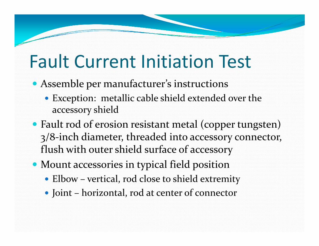
Fault Current Initiation TestAssemble per manufacturer’s instructions
Exception: metallic cable shield extended over the hi ldaccessory shield
Fault rod of erosion resistant metal (copper tungsten)3/8‐inch diameter threaded into accessory connector3/8 inch diameter, threaded into accessory connector,flush with outer shield surface of accessoryMount accessories in typical field positionyp p
Elbow – vertical, rod close to shield extremityJoint – horizontal, rod at center of connector
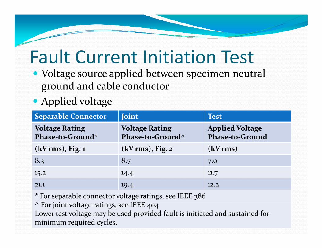
Fault Current Initiation TestVoltage source applied between specimen neutral g pp pground and cable conductorApplied voltage
Separable Connector Joint Test
Voltage RatingPhase‐to‐Ground*
Voltage RatingPhase‐to‐Ground^
Applied Voltage Phase‐to‐Ground
(kV rms), Fig. 1 (kV rms), Fig. 2 (kV rms)
8.3 8.7 7.0
15.2 14.4 11.7
21.1 19.4 12.2
* For separable connector voltage ratings, see IEEE 386^ F j i l i IEEE ^ For joint voltage ratings, see IEEE 404Lower test voltage may be used provided fault is initiated and sustained for minimum required cycles.

Fault Current Initiation TestAvailable short circuit current of 10kA(Note: No specification on tolerance, IEEE 4 assumed)Two applications of fault currentMinimum current flow duration of 10 cyclesFault initiation must occur within 3 secondsInitiate second fault current application in the “ h t t ti l ti ”“shortest practical time”Do not disturb samples between fault applications

Fault Current Initiation Test
Separable ConnectorConnector
Joint

Error in Drawing Place Rod at GREATESTDistance from NEAREST
Fault Rod is in wrong position! Ground
1990 and 2007 Versions
Original 1977 Version
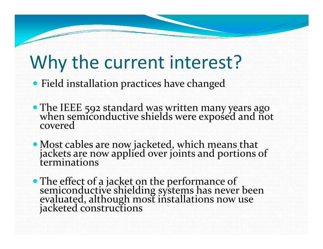
Why the current interest?Field installation practices have changed
The IEEE 592 standard was written many years ago The IEEE 592 standard was written many years ago when semiconductive shields were exposed and not covered
bl k d h h hMost cables are now jacketed, which means that jackets are now applied over joints and portions of terminations
The effect of a jacket on the performance of semiconductive shielding systems has never been evaluated, although most installations now use , gjacketed constructions

Why the current interest?Coverings may affect the distribution of the ionized plasma generated during a faultThi ld i h bili f h hi ldi This could impact the ability of the shielding system to conduct and maintain the fault for sufficient time to clearclearDifferent types of coverings may give different responsep

How might a jacketed joint respond differently during a fault?differently during a fault?
Cold shrink coveringsFle ible e pands on one side pulled in and seals on the
RE-JACKETING MATERIAL, COLD-SHRINK
IONIZED GASES MAY NOT REACH AREA OF NEUTRAL
WIRES
Flexible ‐ expands on one side, pulled in and seals on the other
MATERIAL, COLD SHRINK
JACKET MATERIAL STRETCHES IN RESPONSE
TO FAULT ENERGY RELEASE

How might a jacketed joint respond differently during a fault?differently during a fault?
Heat shrink coveringsL fl ibl i id ll l t Less flexible, more rigid, allows plasma to encompass component or may burn through at the failure site
RE-JACKETING MATERIAL, HEAT-SHRINK
IONIZED GASES MAY NOT REACH AREA OF NEUTRAL
WIRES
JACKET MATERIAL MAY BURN THROUGH AND RELEASE
PLASMA TO THE OUTSIDE ENVIRONMENT

How might a jacketed joint respond differently during a fault?differently during a fault?
Hand‐taped coveringsTapes spread apart, channeling plasma away from shield
RE-JACKETING MATERIAL, HAND-TAPED COVERING
IONIZED GASES MAY NOT REACH AREA OF NEUTRAL
WIRES
JACKET MATERIAL MAY SPREAD APART AND
RELEASE PLASMA TO THE OUTSIDE ENVIRONMENT
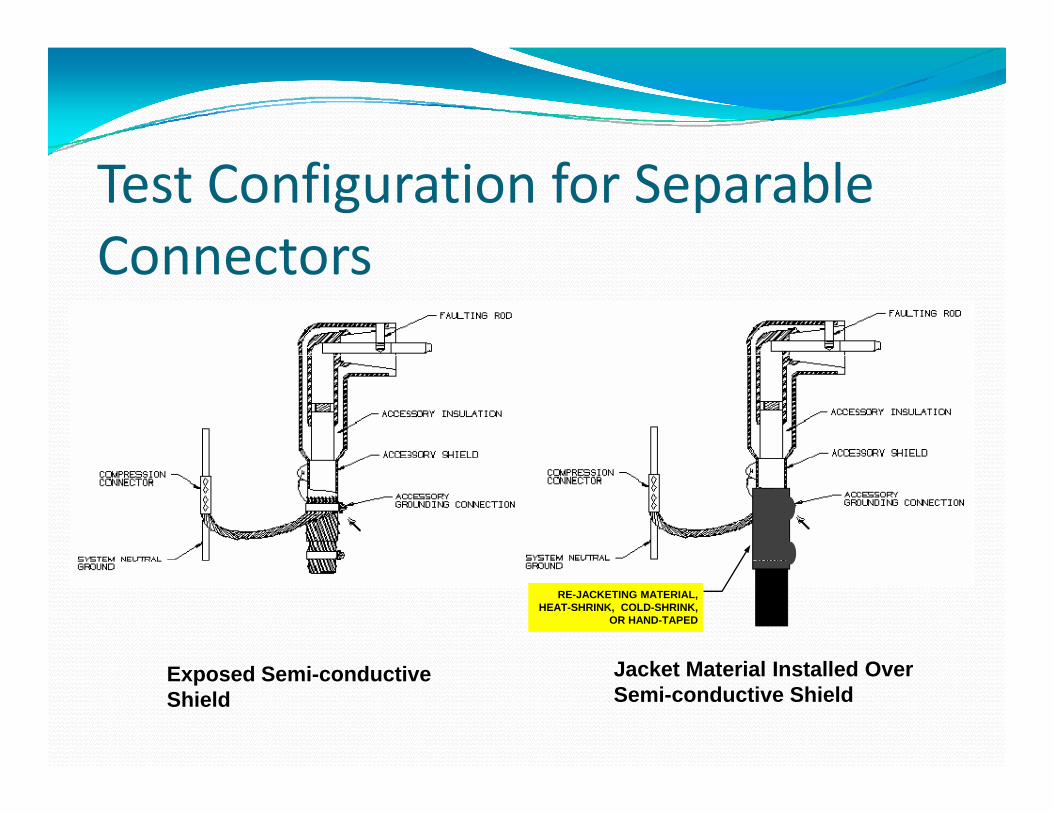
Test Configuration for Separable ConnectorsConnectors
RE-JACKETING MATERIAL, HEAT-SHRINK, COLD-SHRINK,
OR HAND-TAPED
J k t M t i l I t ll d OExposed Semi-conductive Shield
Jacket Material Installed Over Semi-conductive Shield

Test Configuration for Joints
Exposed Semi-conductive RE-JACKETING MATERIAL, HEAT-SHRINK , COLD-SHRINK, OR HAND-TAPED
pShield
Jacket Material Installed Over Semi-conductive Shield
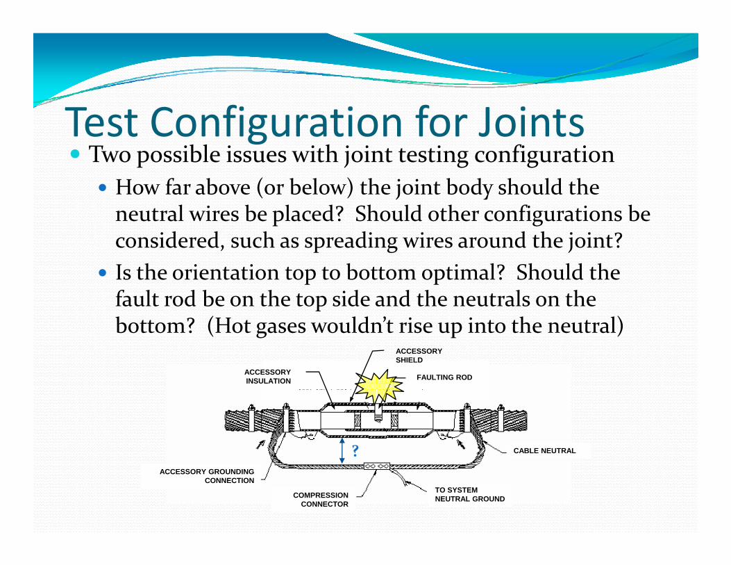
Test Configuration for JointsTwo possible issues with joint testing configuration
How far above (or below) the joint body should the neutral wires be placed? Should other configurations be considered, such as spreading wires around the joint?considered, such as spreading wires around the joint?Is the orientation top to bottom optimal? Should the fault rod be on the top side and the neutrals on the b ? (H ld ’ i i h l)bottom? (Hot gases wouldn’t rise up into the neutral)
FAULTING ROD
ACCESSORY SHIELD
ACCESSORY INSULATION
CABLE NEUTRAL?
TO SYSTEM NEUTRAL GROUNDCOMPRESSION
CONNECTOR
ACCESSORY GROUNDING CONNECTION
What’s Needed or Missing?No mention of what should go in the test reportTime between fault applications is “shortest practical i ” Wh d hi i i h time.” Why not record this time in the test report?Resistance values are recorded when samples are within a given temperature range Why not report the within a given temperature range. Why not report the actual temperature at the time of test?Minimum current flow duration of 10 cycles during Minimum current flow duration of 10 cycles during fault‐current test. Record the actual number of cycles.

What’s Needed or Missing?D l l T f i d l i Developmental Tests for use in developing new materials?Why wait to test on full scale products?Why wait to test on full scale products?Why not test on sample sheets of material?
PlatensPlatensHow could this test be performed?Do the test values scale?

Where Do We Go From Here?IEEE 592‐201?IEEE Standard for Exposed Semiconductive Shields on High Voltage Cable Joints and Separable Insulated High‐Voltage Cable Joints and Separable Insulated Connectors
IEEE 592‐201?IEEE Standard Fault Duty Requirements for y qSemiconductive Shielding of High‐Voltage Electrical Components

D hi A l O h El i lDoes this Apply to Other Electrical Equipment?Equipment?
Polymer Insulated Vacuum RecloserP i d i d iPainted semiconductiveshield over vacuum bottle castingcastingShield fails to carry sufficient fault currentCircuit protective devices did not operateMultiple failures

An Example—Vacuum RecloserDielectric puncture occurring at embedded metallic screenmetallic screenCurrent transfers to painted shieldshieldShield impedance limits fault currentPolymer insulation chars along path to nearest
lli dmetallic ground

Consequences of Failure to Clear FaultFault
Severe electrical noiseFlickerFlickerMolten and flaming components dropping to
dgroundPole fireGround fireGround fireDamage to equipment beyond initial failureService interruption

Consequences of Failure to Clear FaultFault
Safety hazard to personnelDamage may not be externally visibleVoltage present within a normally grounded area

Problems and SolutionsProblemChange in scope would broaden coverage of standard id h j i di i f ICCto areas outside the jurisdiction of ICC
SolutionJ i W ki G i h T&DJoint Working Group with T&D
Are There Other Examples?
Other Problems and Solutions?