IEEE COMMUNICATIONS SURVEYS & TUTORIALS, … · and wavelength assignment algorithms, ... Suresh...
22
IEEE COMMUNICATIONS SURVEYS & TUTORIALS, VOL. 11, NO. 4, FOURTH QUARTER 2009 109 Physical Layer Impairment Aware Routing (PLIAR) In WDM Optical Networks: Issues and Challenges Chava Vijaya Saradhi, Member, IEEE, and Suresh Subramaniam, Senior Member, IEEE Abstract—In WDM optical networks, the physical layer im- pairments (PLIs) and their significance depend on network type—opaque, translucent, or transparent; the reach—access, metro, or core/long-haul; the number and type of network elements—fiber, wavelengths, amplifiers, switching elements, etc.; and the type of applications—real-time, non-real time, mission- critical, etc. In transparent optical networks, PLIs incurred by non-ideal optical transmission media accumulate along an optical path, and the overall effect determines the feasibility of the lightpaths. If the received signal quality is not within the receiver sensitivity threshold, the receiver may not be able to correctly detect the optical signal and this may result in high bit-error rates. Hence, it is important to understand various PLIs and their effect on optical feasibility, analytical models, and monitoring and mitigation techniques. Introducing optical transparency in the physical layer on one hand leads to a dynamic, flexible optical layer with the possibility of adding intelligence such as optical performance monitoring, fault management, etc. On the other hand, transparency reduces the possibility of client layer interaction with the optical layer at intermediate nodes along the path. This has an impact on network design, planning, control, and management. Hence, it is important to understand the techniques that provide PLI information to the control plane protocols and that use this information efficiently to compute feasible routes and wavelengths. The purpose of this article is to provide a comprehensive survey of various PLIs, their effects, and the available modeling and mitigation techniques. We then present a comprehensive survey of various PLI-aware network design techniques, regenerator placement algorithms, routing and wavelength assignment algorithms, and PLI-aware failure recovery algorithms. Furthermore, we identify several important research issues that need to be addressed to realize dynamically reconfigurable next-generation optical networks. We also argue the need for PLI-aware control plane protocol extensions and present several interesting issues that need to be considered in order for these extensions to be deployed in real-world networks. Index Terms—Wavelength division multiplexing, wavelength- routed optical networks, routing and wavelength assignment, optical performance monitoring, optical layer service level agree- ments, transmission impairments, quality of transmission, phys- ical layer impairment aware routing, impairment constraint- based routing, regenerator placement algorithms, physical layer impairment aware control plane, GMPLS-based WDM networks, and IP over WDM networks. Manuscript received 21 December 2007; revised September 2008. Chava Vijaya Saradhi is with the Department of Broadband & Wireless Communications, Create-Net, Trento 38100, Italy (e-mail: [email protected]). Suresh Subramaniam is with the Department of Electrical & Computer Engineering, The George Washington University, Washington DC, USA (e- mail: [email protected]). Digital Object Identifier 10.1109/SURV.2009.090407. I. I NTRODUCTION O PTICAL networks employing dense wavelength division multiplexing (DWDM) and wavelength routing are po- tential candidates for future wide-area backbone networks. These networks provide high throughputs of the order of terabits per second, low error rates, low delays, and can satisfy emerging applications such as supercomputer visualization, medical imaging, and distributed CPU interconnect. Optical fiber transmission and communication systems have evolved tremendously over the past few years. In first-generation op- tical networks, fiber is used purely as a transmission medium, serving as a replacement for copper cable. These networks pro- vide point-to-point transmission service. In these networks all switching and processing of the data is handled by electronics. The key evolutions within the optical networking space over the last several years, e.g. DWDM techniques and DWDM component technologies—such as amplifiers, lasers, filters, optical switches, etc.—have yielded unprecedented levels of bandwidth capacity over single mode fiber (SMF). These advances in turn have led to profound transformations at the networking layer, ushering in revamped, highly-scalable on- demand bandwidth provisioning paradigms. As a result, in second generation optical networks the switching, routing, and restoration functionalities are moved to the optical part of the network. DWDM technology provides several wavelengths per fiber as logical channels. Present DWDM technology can allow transmission rates of up to 10 Gb/s per channel × 40 (80) channels @ 100 GHz (50 GHz) spacing and standard link distances up to 600 km with optical amplifiers placed every 80 km. A DWDM network consists of optical cross-connects (OXCs) interconnected by point-to-point fiber links in an arbitrary mesh topology as shown in Fig. 1. In these networks a connection is referred to as a lightpath, and is established between any two nodes by allocating the same wavelength (if there are no wavelength converters available in the network) on all the links along the chosen route. The requirement that the same wavelength be used on all the links along the chosen route is known as the wavelength continuity constraint. In a transparent optical network, if a lightpath is established between any two nodes, traffic between these nodes can be routed without requiring any intermediate optical-electrical- optical (OEO) conversion and buffering. For example, in Fig. 1, no buffering or OEO conversion is required at OXC 2 for the lightpath identified by (P 1 ,λ 1 ), where P 1 is the route 1553-877X/09/$25.00 c 2009 IEEE Authorized licensed use limited to: Monash University. Downloaded on February 22,2010 at 22:37:10 EST from IEEE Xplore. Restrictions apply.
Transcript of IEEE COMMUNICATIONS SURVEYS & TUTORIALS, … · and wavelength assignment algorithms, ... Suresh...
IEEE COMMUNICATIONS SURVEYS & TUTORIALS, VOL. 11, NO. 4, FOURTH QUARTER 2009 109
Physical Layer Impairment Aware Routing (PLIAR)In WDM Optical Networks: Issues and Challenges
Chava Vijaya Saradhi, Member, IEEE, and Suresh Subramaniam, Senior Member, IEEE
Abstract—In WDM optical networks, the physical layer im-pairments (PLIs) and their significance depend on networktype—opaque, translucent, or transparent; the reach—access,metro, or core/long-haul; the number and type of networkelements—fiber, wavelengths, amplifiers, switching elements, etc.;and the type of applications—real-time, non-real time, mission-critical, etc. In transparent optical networks, PLIs incurred bynon-ideal optical transmission media accumulate along an opticalpath, and the overall effect determines the feasibility of thelightpaths. If the received signal quality is not within the receiversensitivity threshold, the receiver may not be able to correctlydetect the optical signal and this may result in high bit-errorrates. Hence, it is important to understand various PLIs and theireffect on optical feasibility, analytical models, and monitoringand mitigation techniques. Introducing optical transparency inthe physical layer on one hand leads to a dynamic, flexibleoptical layer with the possibility of adding intelligence such asoptical performance monitoring, fault management, etc. On theother hand, transparency reduces the possibility of client layerinteraction with the optical layer at intermediate nodes along thepath. This has an impact on network design, planning, control,and management.Hence, it is important to understand the techniques that
provide PLI information to the control plane protocols andthat use this information efficiently to compute feasible routesand wavelengths. The purpose of this article is to providea comprehensive survey of various PLIs, their effects, andthe available modeling and mitigation techniques. We thenpresent a comprehensive survey of various PLI-aware networkdesign techniques, regenerator placement algorithms, routingand wavelength assignment algorithms, and PLI-aware failurerecovery algorithms. Furthermore, we identify several importantresearch issues that need to be addressed to realize dynamicallyreconfigurable next-generation optical networks. We also arguethe need for PLI-aware control plane protocol extensions andpresent several interesting issues that need to be considered inorder for these extensions to be deployed in real-world networks.
Index Terms—Wavelength division multiplexing, wavelength-routed optical networks, routing and wavelength assignment,optical performance monitoring, optical layer service level agree-ments, transmission impairments, quality of transmission, phys-ical layer impairment aware routing, impairment constraint-based routing, regenerator placement algorithms, physical layerimpairment aware control plane, GMPLS-basedWDM networks,and IP over WDM networks.
Manuscript received 21 December 2007; revised September 2008.Chava Vijaya Saradhi is with the Department of Broadband & Wireless
Communications, Create-Net, Trento 38100, Italy (e-mail: [email protected]).Suresh Subramaniam is with the Department of Electrical & Computer
Engineering, The George Washington University, Washington DC, USA (e-mail: [email protected]).Digital Object Identifier 10.1109/SURV.2009.090407.
I. INTRODUCTION
OPTICAL networks employing dense wavelength divisionmultiplexing (DWDM) and wavelength routing are po-
tential candidates for future wide-area backbone networks.These networks provide high throughputs of the order ofterabits per second, low error rates, low delays, and can satisfyemerging applications such as supercomputer visualization,medical imaging, and distributed CPU interconnect. Opticalfiber transmission and communication systems have evolvedtremendously over the past few years. In first-generation op-tical networks, fiber is used purely as a transmission medium,serving as a replacement for copper cable. These networks pro-vide point-to-point transmission service. In these networks allswitching and processing of the data is handled by electronics.The key evolutions within the optical networking space overthe last several years, e.g. DWDM techniques and DWDMcomponent technologies—such as amplifiers, lasers, filters,optical switches, etc.—have yielded unprecedented levels ofbandwidth capacity over single mode fiber (SMF). Theseadvances in turn have led to profound transformations at thenetworking layer, ushering in revamped, highly-scalable on-demand bandwidth provisioning paradigms. As a result, insecond generation optical networks the switching, routing, andrestoration functionalities are moved to the optical part of thenetwork.
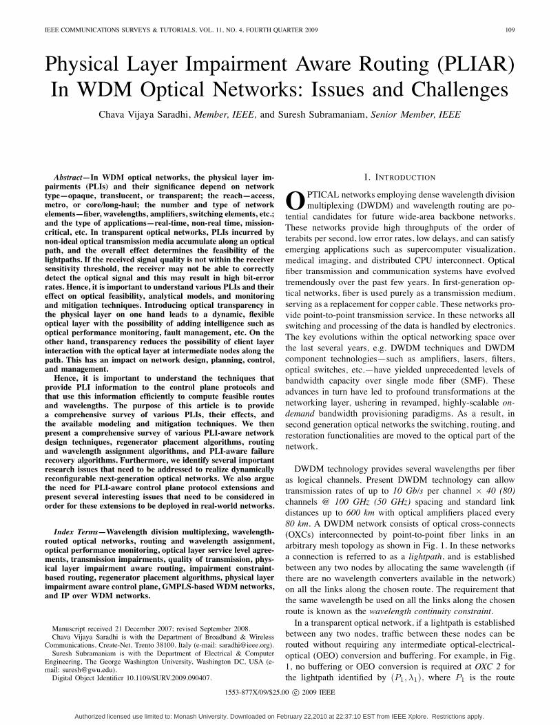
DWDM technology provides several wavelengths per fiberas logical channels. Present DWDM technology can allowtransmission rates of up to 10 Gb/s per channel × 40 (80)channels @ 100 GHz (50 GHz) spacing and standard linkdistances up to 600 km with optical amplifiers placed every80 km. A DWDM network consists of optical cross-connects(OXCs) interconnected by point-to-point fiber links in anarbitrary mesh topology as shown in Fig. 1. In these networksa connection is referred to as a lightpath, and is establishedbetween any two nodes by allocating the same wavelength (ifthere are no wavelength converters available in the network)on all the links along the chosen route. The requirement thatthe same wavelength be used on all the links along the chosenroute is known as the wavelength continuity constraint.In a transparent optical network, if a lightpath is established
between any two nodes, traffic between these nodes can berouted without requiring any intermediate optical-electrical-optical (OEO) conversion and buffering. For example, in Fig.1, no buffering or OEO conversion is required at OXC 2 forthe lightpath identified by (P1, λ1), where P1 is the route
1553-877X/09/$25.00 c© 2009 IEEE
Authorized licensed use limited to: Monash University. Downloaded on February 22,2010 at 22:37:10 EST from IEEE Xplore. Restrictions apply.
110 IEEE COMMUNICATIONS SURVEYS & TUTORIALS, VOL. 11, NO. 4, FOURTH QUARTER 2009
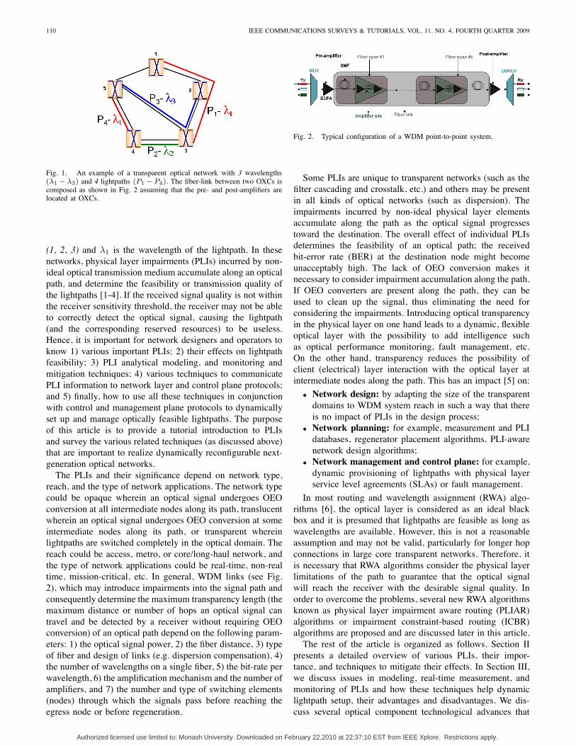
Fig. 1. An example of a transparent optical network with 3 wavelengths(λ1 − λ3) and 4 lightpaths (P1 −P4). The fiber-link between two OXCs iscomposed as shown in Fig. 2 assuming that the pre- and post-amplifiers arelocated at OXCs.
(1, 2, 3) and λ1 is the wavelength of the lightpath. In thesenetworks, physical layer impairments (PLIs) incurred by non-ideal optical transmission medium accumulate along an opticalpath, and determine the feasibility or transmission quality ofthe lightpaths [1-4]. If the received signal quality is not withinthe receiver sensitivity threshold, the receiver may not be ableto correctly detect the optical signal, causing the lightpath(and the corresponding reserved resources) to be useless.Hence, it is important for network designers and operators toknow 1) various important PLIs; 2) their effects on lightpathfeasibility; 3) PLI analytical modeling, and monitoring andmitigation techniques; 4) various techniques to communicatePLI information to network layer and control plane protocols;and 5) finally, how to use all these techniques in conjunctionwith control and management plane protocols to dynamicallyset up and manage optically feasible lightpaths. The purposeof this article is to provide a tutorial introduction to PLIsand survey the various related techniques (as discussed above)that are important to realize dynamically reconfigurable next-generation optical networks.The PLIs and their significance depend on network type,
reach, and the type of network applications. The network typecould be opaque wherein an optical signal undergoes OEOconversion at all intermediate nodes along its path, translucentwherein an optical signal undergoes OEO conversion at someintermediate nodes along its path, or transparent whereinlightpaths are switched completely in the optical domain. Thereach could be access, metro, or core/long-haul network, andthe type of network applications could be real-time, non-realtime, mission-critical, etc. In general, WDM links (see Fig.2), which may introduce impairments into the signal path andconsequently determine the maximum transparency length (themaximum distance or number of hops an optical signal cantravel and be detected by a receiver without requiring OEOconversion) of an optical path depend on the following param-eters: 1) the optical signal power, 2) the fiber distance, 3) typeof fiber and design of links (e.g. dispersion compensation), 4)the number of wavelengths on a single fiber, 5) the bit-rate perwavelength, 6) the amplification mechanism and the number ofamplifiers, and 7) the number and type of switching elements(nodes) through which the signals pass before reaching theegress node or before regeneration.
Fig. 2. Typical configuration of a WDM point-to-point system.
Some PLIs are unique to transparent networks (such as thefilter cascading and crosstalk, etc.) and others may be presentin all kinds of optical networks (such as dispersion). Theimpairments incurred by non-ideal physical layer elementsaccumulate along the path as the optical signal progressestoward the destination. The overall effect of individual PLIsdetermines the feasibility of an optical path; the receivedbit-error rate (BER) at the destination node might becomeunacceptably high. The lack of OEO conversion makes itnecessary to consider impairment accumulation along the path.If OEO converters are present along the path, they can beused to clean up the signal, thus eliminating the need forconsidering the impairments. Introducing optical transparencyin the physical layer on one hand leads to a dynamic, flexibleoptical layer with the possibility to add intelligence suchas optical performance monitoring, fault management, etc.On the other hand, transparency reduces the possibility ofclient (electrical) layer interaction with the optical layer atintermediate nodes along the path. This has an impact [5] on:
• Network design: by adapting the size of the transparentdomains to WDM system reach in such a way that thereis no impact of PLIs in the design process;
• Network planning: for example, measurement and PLIdatabases, regenerator placement algorithms, PLI-awarenetwork design algorithms;
• Network management and control plane: for example,dynamic provisioning of lightpaths with physical layerservice level agreements (SLAs) or fault management.
In most routing and wavelength assignment (RWA) algo-rithms [6], the optical layer is considered as an ideal blackbox and it is presumed that lightpaths are feasible as long aswavelengths are available. However, this is not a reasonableassumption and may not be valid, particularly for longer hopconnections in large core transparent networks. Therefore, itis necessary that RWA algorithms consider the physical layerlimitations of the path to guarantee that the optical signalwill reach the receiver with the desirable signal quality. Inorder to overcome the problems, several new RWA algorithmsknown as physical layer impairment aware routing (PLIAR)algorithms or impairment constraint-based routing (ICBR)algorithms are proposed and are discussed later in this article.The rest of the article is organized as follows. Section II
presents a detailed overview of various PLIs, their impor-tance, and techniques to mitigate their effects. In Section III,we discuss issues in modeling, real-time measurement, andmonitoring of PLIs and how these techniques help dynamiclightpath setup, their advantages and disadvantages. We dis-cuss several optical component technological advances that
Authorized licensed use limited to: Monash University. Downloaded on February 22,2010 at 22:37:10 EST from IEEE Xplore. Restrictions apply.

SARADHI and SUBRAMANIAM: PHYSICAL LAYER IMPAIRMENT AWARE ROUTING (PLIAR) IN WDM OPTICAL NETWORKS: ISSUES AND CHALLENGES 111
are required to achieve dynamically reconfigurable PLI-awarelightpath setup in Section IV. Several optical layer SLAs thatare important in assuring the received optical signal quality aredefined in Section V. Section VI provides a detailed PLI-awarestatic network design methodology and issues. We presentseveral issues in dynamic routing for single and multi-domainnetworks in Section VII and Section VIII, respectively. InSection IX, we provide a brief overview of various PLI-awarewavelength assignment algorithms and discuss their benefits.We discuss the urgent need for standard control plane exten-sions, and present several possible alternatives and issues inSection X. We discuss the importance of PLI-aware fast failurerecovery techniques and present several protection/restorationalgorithms in Section XI. Other important issues such asefficient regenerator placement algorithms, effect of PLIs onincrease in network capacity, physical layer security threats,optical grooming, etc., are discussed in Section XII. Finally,we conclude this article in Section XIII and provide directionsfor future research.
II. OVERVIEW OF PHYSICAL LAYER IMPAIRMENTS (PLIS)
In this section we describe various PLIs, their effects,and mitigation techniques. PLIs are broadly classified intotwo categories: linear and non-linear impairments [1-4]. Theterms linear and non-linear in fiber optics mean intensity-independent and intensity-dependent, respectively. The linearimpairments are static in nature and non-linear impairmentsare dynamic in nature. The non-linear impairments stronglydepend on the current allocation of route and wavelength, i.e.,on the current status of allocated lightpaths. Moreover, theallocation of route and wavelength for a new lightpath requestaffects the existing lightpaths in the network.
A. Linear Impairments (LIs)
A) Power Losses: Power loss can be defined as the opticalloss that is accumulated from source to destination along fiber-links and is normally made up of intrinsic fiber losses andextrinsic bending losses [1, 7]. Intrinsic fiber losses are dueto attenuation, absorption, reflections, refractions, Rayleighscattering, optical component insertion losses, etc. Let Pin bethe power launched at the input of a fiber of length L; thenthe output power Pout is given by Pout = Pin · e−αL, whereα is the fiber attenuation coefficient. The loss introduced bythe insertion of optical components, such as couplers, filters,multiplexers/demultiplexers, and switches, into the opticalcommunications system is called insertion loss and is usuallyindependent of wavelength. The extrinsic losses are due tomicro and macro bending losses. Additional losses occur dueto the combined effects of dispersion resulting from inter-symbol interference (ISI), mode-partition noise, and laserchirp as discussed later in this section.B) Chromatic Dispersion (CD): The degradation of an opti-
cal signal caused by the various spectral components travelingat their own different velocities is called dispersion. CD causesan optical pulse to broaden such that it spreads into the timeslots of the other pulses. It is considered as the most seriouslinear impairment for systems operating at bit-rates higher
than 2.5 Gb/s. CD depends on bit-rate, modulation format,type of fiber, and the use of dispersion compensation fiber(DCF) modules. The total dispersion at the end of a lightpathis the sum of dispersions on each fiber-link of the consideredlightpath, where the dispersion on a fiber-link is the sum ofdispersions on the fiber-spans that compose the link (see Fig.2). Most commonly deployed compensation techniques arebased on DCF. Dispersion compensation techniques are usefulin long-haul as well as metro networks. A fiber of length Lf
and dispersion Df can be compensated by using a spool ofDCF of length Lc and dispersion parameter Dc such that thedispersion at the end of the fiber is close to zero and satisfiesDfLf + DcLc = 0. Due to imperfect matching betweenthe dispersion slopes of CD and DCF, some wavelengthsmay be over-compensated and some others may be under-compensated. Moreover DCF modules may only be availablein fixed lengths of compensating fiber. Hence, sometimes itmay be difficult to find a DCF that exactly compensates theCD introduced by the fiber, leading to residual CD. A typicalvalue of dispersion compensation tolerance in commercialreceivers is around±800 ps/nm for non-return-to-zero (NRZ)10 Gb/s, while it is ±160 ps/nm for optical duobinary (ODB)40 Gb/s [7].
C) Polarization Mode Dispersion (PMD): Anywhere alonga fiber-span, fiber could be non-circular, contain impurities,or be subject to environmental stress such as local heatingor movement. These irregularities present obstacles to anoptical pulse along its path. These obstacles cause differentpolarizations of the optical signal to travel with differentgroup velocities resulting in pulse spread in the frequencydomain, known as PMD. The differential group delay (DGD)is proportional to the square root of fiber length L, i.e.,Δτ = DPMD · √L, where DPMD is the PMD parameterof the fiber and typically measured in ps/
√km. Because
of the√
L dependence, the PMD-induced pulse broadeningis relatively small compared to CD. The PMD on a fiber-link is a function of PMD on each fiber-span and is givenby PMDfiber−link =
√∑fiber−spans PMD(f)2 (see Fig.
2). The PMD at the end of a lightpath is PMDlightpath =√∑fiber links along the route (PMD(f)2.
The PMD values vary from fiber to fiber in the rangeof 0.01-10 ps/
√km [7]. PMD becomes a major limiting
factor for WDM systems designed for longer distances athigher bit-rates. The effect of second and higher order PMDbecomes prominent at high-bit rates exceeding 40 Gb/s. PMD-induced problems can be reduced by shortening the opticaltransmission distance by placing OEO regenerators betweentwo optical nodes. However, as most long-haul DWDM sys-tems are multi-wavelength, the transmission link must firstbe demultiplexed, then regenerated, and then multiplexedagain, which is a very expensive operation. Another alternativeis to use dispersion compensation modules (DCM) at opti-cal add/drop multiplexers (OADMs), optical cross-connects(OXCs), or amplifier sites to compensate for accumulatedPMD on an optical path. Because PMD effects are randomand time-dependent, this requires an adaptive/active PMDcompensator that responds to feedback over time. Hence, themost reliable and efficient PMD compensation technology is
Authorized licensed use limited to: Monash University. Downloaded on February 22,2010 at 22:37:10 EST from IEEE Xplore. Restrictions apply.

112 IEEE COMMUNICATIONS SURVEYS & TUTORIALS, VOL. 11, NO. 4, FOURTH QUARTER 2009
the use of adaptive optics to realign and correct the pulses ofdispersed optical bits.D) Polarization Dependent Loss (PDL): The two polariza-
tion components along the two axes of a circular fiber sufferdifferent rates of loss due to irregularities in the fiber, therebydegrading signal quality in an uncontrolled and unpredictablemanner and introducing fluctuations in optical signal to noiseratio (OSNR). The combined effect of PMD and PDL canfurther degrade the optical signal quality. PDL is a measureof the peak-to-peak difference in transmission of an opticalcomponent/system w.r.t. all possible states of polarization andis given by PDLdB = 10 · log(PMax/PMin), where PMax
and PMin are the maximum and minimum output power, re-spectively. PDL mainly occurs in passive optical components.The most common passive optical components that exhibitPDL include couplers, isolators, multiplexers/demultiplexers,and photodetectors. The polarization scanning technique (PST)and the Mueller matrix method (MMM) are suitable methodsfor measuring the PDL [8]. While the PST is preferable fordetermining PDL at a specific wavelength, the MMM hasclear advantages when PDL must be characterized at numerouswavelength points with equal spacing.E) Amplifier Spontaneous Emission Noise (ASE): The
primary source of additive noise in optically amplified systemsis due to the ASE produced by the optical amplifiers usedas intermediate repeaters and as preamplifiers at the receiverend. This noise is often quantified with noise figure (NF).The NF is a factor which says how much higher the noisepower spectral density of the amplified output is comparedwith the input noise power spectral density times the ampli-fication factor and is often specified in decibels (dB). ASEis emitted by the amplifier in both the forward and reversedirections, but only the forward ASE is a direct concern tosystem performance since that noise will co-propagate with thesignal to the receiver where it degrades system performance.Counter-propagating ASE can, however, lead to degradationof the amplifier’s performance since the ASE can deplete theinversion level and thereby reduce the gain of the amplifier.Excess ASE is an unwanted effect in lasers, since it dissipatessome of the laser’s power. In optical amplifiers, ASE limits theachievable gain of the amplifier and increases its noise level.The ASE noise mixes with the optical signal and produces beatnoise components at the square-law receiver. The ASE noise isvery broadband (∼ 40 nm) and needs to be carefully analyzedto evaluate its degrading effect on system performance. ASEeffects may be mitigated by increasing the input laser intensity,decreasing the amplifier facet reflectivities, or tuning themaster oscillator so that it is resonant with the amplifier.F) Crosstalk (CT): Linear crosstalk arises due to incom-
plete isolation of WDM channels by optical componentssuch as OADMs, OXCs, multiplexers/demultiplexers, and op-tical switches, i.e., the effect of signal power leakage fromother WDM channels on the desired channel. It is differentfrom non-linear crosstalk involving non-linear fiber interaction(such as cross-phase modulation, stimulated Raman scattering,etc.). Linear crosstalk depends on the ratio of the optical pow-ers of two channels, whereas non-linear crosstalk (discussed inSection II.B) depends on absolute powers. Linear crosstalk canbe either incoherent (i.e., heterowavelength or out-of-band) or
Fig. 3. Typical OXC structure with N ports and M wavelengths.
coherent (i.e., homowavelength or in-band). Consider a case inwhich a tunable optical filter is used to select a single channelamong the W channels incident on it. If the optical filter isset to pass the kth channel, the optical power reaching theoutput of the filter can be written as P = Pk +
∑Ww �=k TkjPj
where Pk is the power in the kth channel and Tkj is the filtertransmittivity for channel j when the channel k is selected. Foran ideal filter Tkj should be zero. Crosstalk occurs if Tkj �= 0for j �= k. This is out-of-band crosstalk because it belongs tothe channels lying outside the spectral band occupied by thechannel selected. It is incoherent because it depends only onthe power of the neighboring channels.The in-band crosstalk can be easily understood by consid-
ering a typical structure of an OXC without in-built amplifiersas shown in Fig. 3. The OXC consists of N fiber ports andM optical switches. Wavelength 1 in input fiber 1, denotedby λ11, is affected by the N − 1 crosstalk components dueto the leakage from the N − 1 signals with wavelength 1on the other N − 1 input fibers, λ21, λ31 . . . , λN1, whenpassing through the optical switch 1 (shown in red dottedlines). Similarly, when wavelength 1 is demultiplexed to onepath, there will be a fraction of it in each of the otherM − 1 outputs of the corresponding demultiplexer. Passedthrough the optical switches, the main signal is multiplexedwith M − 1 signals with different wavelengths. At the sametime, the M − 1 crosstalk contributions of wavelength 1in these M − 1 paths are combined with the main signal(shown in blue dashed lines). Assume ε is the isolation ofmultiplexers/demultiplexers, P is power of the input signal,and then the crosstalk contributions are ε2(M − 1)P . Thecomputation of crosstalk becomes quite complicated as thenumber of crosstalk elements which the signal passes throughincreases, and should be considered in the design of WDMnetworks. Crosstalk effects can be mitigated by the use ofintelligent wavelength assignment techniques as discussed inSection IX.G) Filter Concatenation and Amplifier Tilt Effects: The
narrowing of spectral width of the signal as it traverses througha set of filters along a path is called filter concatenation (FC)effect. The penalty induced by FC depends on the route, themodulation type used, and the number of network elementsthe signal traverses before it reaches the destination. Low-passfilter-based duobinary (LPF-DB) modulation offers greater
Authorized licensed use limited to: Monash University. Downloaded on February 22,2010 at 22:37:10 EST from IEEE Xplore. Restrictions apply.

SARADHI and SUBRAMANIAM: PHYSICAL LAYER IMPAIRMENT AWARE ROUTING (PLIAR) IN WDM OPTICAL NETWORKS: ISSUES AND CHALLENGES 113
tolerance to FC effects than NRZ modulation [9]. The mainlimitation of Erbium doped fiber amplifier (EDFA) stems fromthe spectral non-uniformity of the amplifier gain. As a result,different wavelengths of a WDM signal are amplified bydifferent amounts causing lambda-dependent effects knownas amplifier tilt effects. The problem becomes quite severein long-haul WDM networks, where the signal undergoesamplification over a chain of in-line amplifiers. Tilt effects canbe reduced with the application of gain-flattening techniquesusing optical filters that have gain profiles that are the inverseof the gain profiles of the amplifiers. Alternatively, gain-clamped EDFAs may be used.
B. Non-linear Impairments (NLIs)
The worries that plagued optical fiber communication inthe early days were fiber attenuation and, sometimes, fiberdispersion; however, these issues are dealt with using a varietyof dispersion compensation techniques. However, fiber non-linearities present a new realm of obstacles that must beovercome. Effects of non-linear impairments become crucialas data transmission rates, transmission lengths, number ofwavelengths, and optical power levels increase in addition toreduction in channel spacing [2]. Network designers must beaware of these limitations and of the steps that can be taken tominimize the detrimental effects of these fiber non-linearities.The response of any dielectric medium to light becomes
non-linear under intense electromagnetic field, and opticalfibers are no exception. Due to anharmonic motion of boundelectrons the total polarization P induced by electric dipolesis not linear in the electric field E, but satisfies a more generalrelation as P = ε0(χ(1).E1 + χ(2).E2 + χ(3).E3 + . . .),where ε0 is the permittivity of vacuum and χ(k) is the kth
order susceptibility. The predominant contribution to P isfrom linear susceptibility χ(1). For a medium like fiber withsymmetric molecules, χ(2) vanishes. Therefore optical fibersdo not exhibit second order nonlinear refractive effects. Hence,the third order susceptibility χ(3) is responsible for the lowest-order non-linear effects such as non-linear refraction (SectionII.B.A), third order harmonic generation (Section II.B.B), andfour-wave mixing (Section II.B.C) as discussed later.The non-linear effects in optical fiber occur either due to
change in the refractive index of the medium with opticalintensity (power) or due to inelastic-scattering phenomenon.A general classification of non-linear effects in fiber mediumis shown in Fig. 4 [2]. The dependence of refractive index onpower is responsible for Kerr effect which produces three dif-ferent kinds of effects—self-phase modulation (SPM), cross-phase modulation (XPM), and four-wave mixing (FWM),depending on the type of input signal. At high power levels,the lightwaves (optical signals) interact with the phonons ofthe fiber medium resulting in scattering phenomenon. Theintensity of scattered light grows exponentially if the inci-dent power exceeds a certain threshold value. The inelasticscattering phenomenon can induce stimulated effects such asstimulated Brillouin scattering (SBS) and stimulated Ramanscattering (SRS). The Brillouin generated phonons (acoustic)are coherent and give rise to a macroscopic acoustic wave inthe fiber, whereas, in Raman scattering, the phonons (optical)
Fig. 4. Classification of non-linear effects in fiber medium.
are incoherent and no macroscopic wave is generated. All non-linear effects, except SPM and XPM, provide gains to somechannel at the expense of depleting power from other channels.SPM and XPM affect only the phase of the optical signaland can cause spectral broadening, which leads to increaseddispersion. A comparison of various non-linear effects in fibermedium is presented in Table I [2, 10].The importance of non-linear effects is growing due to
1) increase in optical power levels to increase the opticalreach, 2) recent developments in optical components such asEDFA and DWDM systems to build more flexible networks,3) increase in channel bit-rate to increase the traffic carryingcapacity of wavelengths, and 4) decrease in channel spacingto increase the number of wavelengths and overall networkcapacity. Although the individual power in each channel maybe below the one needed to produce non-linearities, the totalpower summed over all channels in a multi-wavelength WDMsystem can become significant. The combination of high totaloptical power and a large number of channels at closely spacedwavelengths is ideal for many kinds of non-linear effects. Forall these reasons it is important to understand and be ableto accurately measure fiber non-linearities. In the following,we briefly explain the reasons behind each of these non-lineareffects and discuss some possible solutions to overcome theseeffects.
A) Self-Phase Modulation (SPM): The non-linear phasemodulation of an optical pulse caused by its own intensityin an optical medium is called SPM. An ultra-short opticalpulse, when traveling in a medium, will induce a time varyingrefractive index of the medium, i.e., the higher intensityportions of an optical pulse encounter a higher refractive indexof the fiber compared with the lower intensity portions. Thisresults in a positive refractive index gradient (dn/dt) at theleading edge of the pulse and a negative refractive indexgradient (−dn/dt) at its trailing edge. This temporally varyingrefractive index change results in a temporally varying phasechange leading to frequency chirping, i.e., the leading edge ofthe pulse finds frequency shift towards the higher side whereasthe trailing edge experiences shift towards the lower side.Hence, the primary effect of SPM is to broaden the pulse inthe frequency domain, keeping the temporal shape unaltered.As the chirping effect is proportional to the transmitted signalpower, the SPM effects are more pronounced in systems withhigh transmitted power. SPM is the strongest among the Kerreffects for DWDM systems working at 100 GHz spacing. Thechirp also depends on the input pulse shape. The appropriatechirping of input signals using chirped RZ (CRZ) modulationcan reduce the SPM effects [11]. The effects produced by non-linear SPM and linear dispersion are opposite in nature. Byproper choice of pulse shape and input power, one effect will
Authorized licensed use limited to: Monash University. Downloaded on February 22,2010 at 22:37:10 EST from IEEE Xplore. Restrictions apply.

114 IEEE COMMUNICATIONS SURVEYS & TUTORIALS, VOL. 11, NO. 4, FOURTH QUARTER 2009
compensate for another, leading to undistorted pulse in bothtime and frequency domains. Such a pulse is called a solitonpulse and is useful in high-bandwidth optical communicationsystems.B) Cross-Phase Modulation (XPM): The non-linear re-
fractive index seen by an optical pulse depends not onlyon the intensity of the pulse but also on the intensity ofthe other co-propagating optical pulses, i.e., the non-linearphase modulation of an optical pulse caused by fluctuations inintensity of other optical pulses is called XPM. The result ofXPM may be asymmetric spectral broadening and distortionof the pulse shape. XPM hinders the system performancethrough the same mechanism as SPM: chirping frequency andchromatic dispersion. XPM damages the system performanceeven more than SPM and influences it severely when thenumber of channels is large. The XPM-induced phase shiftcan occur only when two pulses overlap in time. Due to thisoverlap, the intensity-dependent phase shift and consequentchirping is enhanced, leading to enhanced pulse broadening.The effects of XPM can be reduced by increasing the wave-length spacing between individual channels. Another way toreduce XPM effects is by careful selection of bit-rates foradjacent channels that are not equal to the present channel’s.For increased wavelength spacing, the pulses overlap for sucha short time that XPM effects are virtually negligible. XPMis more important at 50 (or less) GHz spacing compared to100 GHz spacing.C) Four Wave Mixing (FWM): FWM originates from
third order non-linear susceptibility (χ(3)) in optical links. Ifthree optical signals with carrier frequencies ω1, ω2 and ω3,co-propagate inside a fiber simultaneously, (χ(3)) generatesa fourth signal with frequency ω4, which is related to theother frequencies by ω4 = ω1 ± ω2 ± ω3. In general forW wavelengths launched into a fiber, the number of FWMchannels produced is M = W 2(W − 1)/2). The FWM effectis independent of the bit-rate and is critically dependent on thechannel spacing and fiber dispersion. Decreasing the channelspacing increases the four-wave mixing effect. FWM hassevere effects in a WDM system, which uses dispersion-shiftedfiber. If there is some dispersion in the fiber, then the effectof FWM is reduced. This is why non-zero dispersion-shiftedfibers are normally used in WDM systems. Another way toreduce FWM effect is to employ unequal channel spacing insuch a way that the generated signals do not interfere with theoriginal signals.D) Stimulated Brillouin Scattering (SBS): SBS occurs
when an optical signal in fiber interacts with the densityvariations such as acoustic phonons and changes its path. InSBS, the scattering process is stimulated by photons with awavelength higher than the wavelength of the incident signal.SBS is recognized as the most dominant fiber non-linearscattering effect. SBS sets an upper limit on the amountof optical power that can be launched into an optical fiber.When input optical power exceeds the SBS threshold, asignificant amount of the transmitted light is redirected backto the transmitter leading to saturation of optical power inthe receiver, and introducing noise that degrades the BERperformance. The SBS threshold depends on the line-widthof the optical source, with narrow line-width sources having
TABLE IA COMPARISON OF NON-LINEAR EFFECTS IN FIBER MEDIUM.
Non-linear Refractive EffectsCharacteristic SPM XPM FWMBit-rate Dependent Dependent IndependentOrigin χ(3) χ(3) χ(3)
Effect Phase shift dueto pulse itself
Phase shiftdue to co-propagatingsignal
New waves aregenerated
Shape ofbroadening
Symmetrical Asymmetrical No shapechange
Energy transferbetweenmedium andpulse
No No No
Effect of chan-nel spacing
No Increasesas channelspacingdecreases
Increasesas channelspacingdecreases
considerably lower SBS thresholds. The back-scattered signalscan be measured using a Fabry-Perot interferometer or pumpprobe or self-heterodyne techniques. Externally modulatingthe transmitter provides one way to broaden the line-width ofthe optical source. Hence, it is particularly important to controlSBS in high-speed transmission systems that use externalmodulators and continuous wave (CW) laser sources.
E) Stimulated Raman Scattering (SRS): In WDM systems,if two or more optical signals at different wavelengths areinjected into a fiber, the SRS effect causes optical signalpower from lower wavelength optical channels to be trans-ferred to the higher wavelength optical channels. This canskew the power distribution among the WDM channels—reducing the signal-to-noise ratio of the lower wavelengthchannels and introducing crosstalk on the higher wavelengthchannels. Both of these effects can lower the information-carrying capacity of the optical transmission system. SRSoccurs at significantly higher optical powers than SBS, withthreshold powers of the order of watts for SRS comparedto milliwatts for SBS. Unlike SBS, SRS scatters in bothforward and reverse directions. The effect of SRS, i.e., Ramangain coefficient, can be measured using relative cross-sectionmethod or pulse-scanning technique or Raman amplificationmethod. Several optical filtering techniques are proposed tosuppress SRS interactions in optical fiber systems. The filters,when inserted appropriately into the transmission link, caneffectively suppress the SRS power flow from the WDMchannels to lower frequency noise. Furthermore, usage of ahigh-pass filter can enhance the SRS threshold in an opticalfiber.
III. PLI MODELING, REAL-TIME MEASUREMENT, ANDMONITORING
Physical layer monitoring in WDM networks could be im-plemented at the impairment level (OIM—optical impairmentmonitoring) or at the aggregate level where the overall perfor-mance is monitored (OPM—optical performance monitoring).In the first approach, every network element should reportits status in terms of input/output power, noise figure, disper-sion, etc. In the second approach, optical monitoring systems
Authorized licensed use limited to: Monash University. Downloaded on February 22,2010 at 22:37:10 EST from IEEE Xplore. Restrictions apply.
SARADHI and SUBRAMANIAM: PHYSICAL LAYER IMPAIRMENT AWARE ROUTING (PLIAR) IN WDM OPTICAL NETWORKS: ISSUES AND CHALLENGES 115
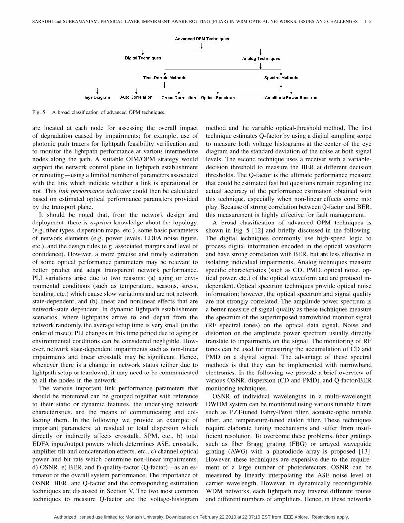
Fig. 5. A broad classification of advanced OPM techniques.
are located at each node for assessing the overall impactof degradation caused by impairments; for example, use ofphotonic path tracers for lightpath feasibility verification andto monitor the lightpath performance at various intermediatenodes along the path. A suitable OIM/OPM strategy wouldsupport the network control plane in lightpath establishmentor rerouting—using a limited number of parameters associatedwith the link which indicate whether a link is operational ornot. This link performance indicator could then be calculatedbased on estimated optical performance parameters providedby the transport plane.It should be noted that, from the network design and
deployment, there is a-priori knowledge about the topology,(e.g. fiber types, dispersion maps, etc.), some basic parametersof network elements (e.g. power levels, EDFA noise figure,etc.), and the design rules (e.g. associated margins and level ofconfidence). However, a more precise and timely estimationof some optical performance parameters may be relevant tobetter predict and adapt transparent network performance.PLI variations arise due to two reasons: (a) aging or envi-ronmental conditions (such as temperature, seasons, stress,bending, etc.) which cause slow variations and are not networkstate-dependent, and (b) linear and nonlinear effects that arenetwork-state dependent. In dynamic lightpath establishmentscenarios, where lightpaths arrive to and depart from thenetwork randomly, the average setup time is very small (in theorder of msec); PLI changes in this time period due to aging orenvironmental conditions can be considered negligible. How-ever, network state-dependent impairments such as non-linearimpairments and linear crosstalk may be significant. Hence,whenever there is a change in network status (either due tolightpath setup or teardown), it may need to be communicatedto all the nodes in the network.The various important link performance parameters that
should be monitored can be grouped together with referenceto their static or dynamic features, the underlying networkcharacteristics, and the means of communicating and col-lecting them. In the following we provide an example ofimportant parameters: a) residual or total dispersion whichdirectly or indirectly affects crosstalk, SPM, etc., b) totalEDFA input/output powers which determines ASE, crosstalk,amplifier tilt and concatenation effects, etc., c) channel opticalpower and bit rate which determine non-linear impairments,d) OSNR, e) BER, and f) quality-factor (Q-factor)—as an es-timator of the overall system performance. The importance ofOSNR, BER, and Q-factor and the corresponding estimationtechniques are discussed in Section V. The two most commontechniques to measure Q-factor are the voltage-histogram
method and the variable optical-threshold method. The firsttechnique estimates Q-factor by using a digital sampling scopeto measure both voltage histograms at the center of the eyediagram and the standard deviation of the noise at both signallevels. The second technique uses a receiver with a variable-decision threshold to measure the BER at different decisionthresholds. The Q-factor is the ultimate performance measurethat could be estimated fast but questions remain regarding theactual accuracy of the performance estimation obtained withthis technique, especially when non-linear effects come intoplay. Because of strong correlation between Q-factor and BER,this measurement is highly effective for fault management.A broad classification of advanced OPM techniques is
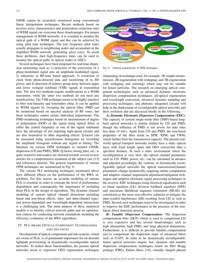
shown in Fig. 5 [12] and briefly discussed in the following.The digital techniques commonly use high-speed logic toprocess digital information encoded in the optical waveformand have strong correlation with BER, but are less effective inisolating individual impairments. Analog techniques measurespecific characteristics (such as CD, PMD, optical noise, op-tical power, etc.) of the optical waveform and are protocol in-dependent. Optical spectrum techniques provide optical noiseinformation; however, the optical spectrum and signal qualityare not strongly correlated. The amplitude power spectrum isa better measure of signal quality as these techniques measurethe spectrum of the superimposed narrowband monitor signal(RF spectral tones) on the optical data signal. Noise anddistortion on the amplitude power spectrum usually directlytranslate to impairments on the signal. The monitoring of RFtones can be used for measuring the accumulation of CD andPMD on a digital signal. The advantage of these spectralmethods is that they can be implemented with narrowbandelectronics. In the following we provide a brief overview ofvarious OSNR, dispersion (CD and PMD), and Q-factor/BERmonitoring techniques.OSNR of individual wavelengths in a multi-wavelength
DWDM system can be monitored using various tunable filterssuch as PZT-tuned Fabry-Perot filter, acoustic-optic tunablefilter, and temperature-tuned etalon filter. These techniquesrequire elaborate tuning mechanisms and suffer from insuf-ficient resolution. To overcome these problems, fiber gratingssuch as fiber Bragg grating (FBG) or arrayed waveguidegrating (AWG) with a photodiode array is proposed [13].However, these techniques are expensive due to the require-ment of a large number of photodetectors. OSNR can bemeasured by linearly interpolating the ASE noise level atcarrier wavelength. However, in dynamically reconfigurableWDM networks, each lightpath may traverse different routesand different numbers of amplifiers. Hence, in these networks
Authorized licensed use limited to: Monash University. Downloaded on February 22,2010 at 22:37:10 EST from IEEE Xplore. Restrictions apply.
116 IEEE COMMUNICATIONS SURVEYS & TUTORIALS, VOL. 11, NO. 4, FOURTH QUARTER 2009
OSNR cannot be accurately monitored using conventionallinear interpolation techniques. Recent methods based onreceiver noise characteristics and polarization extinction ratioof WDM signal can overcome these disadvantages. For propermanagement of WDM networks, it is essential to monitor theoptical path of a WDM signal and this can be achieved byusing pilot tone techniques. The low frequency pilot tonesusually propagate to neighboring nodes and accumulate in theamplified WDM network, generating ghost tones. To avoidthese problems, dual high-frequency tones can be used tomonitor the optical paths in optical nodes or OXCs.Several techniques have been proposed for real-time disper-
sion monitoring such as 1) detection of the conversion of aphase-modulated signal into an amplitude-modulated signal,2) subcarrier or RF-tone based approach, 3) extraction ofclock from photo-detected data and monitoring of its RFpower, and 4) detection of relative group delay between upperand lower vestigial sideband (VSB) signals in transmitteddata. The first two methods require modifications to a WDMtransmitter, while the latter two methods do not need anymodifications. The VSB technique seems to be highly sensitiveto fiber non-linearity and transmitter chirp. It can be appliedto WDM signals by sweeping the optical filter. PMD canbe monitored based on spectral analysis of RF tones, butthese techniques cannot isolate individual impairments. ThePMD monitoring techniques based on measurement of degreeof polarization (DOP) of the signal using optical filters ateither the central frequency or one of the signal sidebandshave the advantage of not requiring high-speed circuits andare also insensitive to other degrading effects. Q-factor canbe measured using asynchronous histograms by recordingthe amplitude histogram without any regard to timing. Theliterature on various OPM techniques to monitor OSNR,dispersion (CD and PMD), BER, Q-factor, timing jitter, etc., isquite extensive and readers are directed towards several reviewarticles for a comprehensive treatment of the subject (see [13]and references therein). The general requirements of variousOPM techniques are summarized in Fig. 6.The various PLI monitoring techniques mentioned above
have different effects on the performance of the RWA al-gorithms. For this reason, an accurate modeling of variousPLIs is essential in order to estimate the level of performancedegradation and consequently the importance of includingthese PLIs in the design of algorithms. The dynamic channelmodeling of various optical channel distortions includinglinear and non-linear effects, inter- and intra-channel types,and power-dependent and wavelength-dependent interactionsis a challenging task. The main purpose of these analyticalmodels is to identify critical network paths and set optimiza-tion criteria for conducting network simulations including theefficiency evaluation of the RWA algorithms.
IV. PLI-AWARE OPTICAL COMPONENT TECHNOLOGIESAND ADVANCES
Development of optical components and sub-systems, whichare aware of PLIs, is of paramount importance for on-demandlightpath provisioning in dynamically reconfigurable opticalnetworks. To realize these functionalities, the present opticalnetworks resort to expensive OEO regeneration techniques
Fig. 6. General requirements of OPM techniques.
(depending on technique used, for example, 1R-simple retrans-mission, 2R-regeneration with reshaping, and 3R-regenerationwith reshaping and retiming) which may not be suitablefor future networks. The research on emerging optical com-ponent technologies such as advanced dynamic electronicdispersion compensation techniques, all-optical regenerationand wavelength conversion, advanced dynamic sampling andprocessing techniques, and photonic integrated circuits willhelp in the deployment of reconfigurable optical networks andtheir evolution and are discussed briefly in the following:A) Dynamic Electronic Dispersion Compensation (EDC):
The capacity of current single-mode fiber (SMF)-based long-haul optical networks is mainly limited by CD and PMD,though the influence of PMD is not severe for data ratesless than 10 Gb/s. Apart from CD and PMD, the non-linearproperties of the fiber result in SPM, XPM, and FWM,which further limit the transmission capacity. The present real-world optical transport networks mainly have a static opticallayer with fixed length spans and OEO conversion after aspecified distance. In such a static environment where thereconfiguration is very slow, the optical channel parameterssuch as CD, PMD, power, etc., can be calculated in advanceand adjusted accordingly. By contrast, in dynamically recon-figurable optical networks the optical transmission/channelparameters change dynamically, requiring online computationand adaptive channel impairment adjustment/mitigation tech-niques and adaptive electronic signal processing techniques inthe receiver. EDC techniques using electrical equalization suchas linear equalizer (LE), decision feedback equalizer (DFE)and maximum likelihood sequence estimation (MLSE) areconsidered as the most cost-effective solutions to mitigate theinter-symbol interference (ISI) resulting from CD as well asPMD. Several such techniques need to be investigated in orderto improve the EDC performance in the presence of the non-linear direct detection process.B) Tunable Dispersion Compensation: The dispersion
compensation fiber (DCF) which is used to compensate CDis very expensive and has several disadvantages such ashigh attenuation, high PMD, and large physical dimensions.Furthermore, it is difficult to provide tunable compensationand to compensate the dispersion slope of advanced fiberssuch as G.655. In order to be dynamically reconfigurable,future optical networks require fast, dynamic and tunabledispersion compensation techniques based on fiber Bragggratings (FBG), Etalon filters [14], virtually imaged phased
Authorized licensed use limited to: Monash University. Downloaded on February 22,2010 at 22:37:10 EST from IEEE Xplore. Restrictions apply.
SARADHI and SUBRAMANIAM: PHYSICAL LAYER IMPAIRMENT AWARE ROUTING (PLIAR) IN WDM OPTICAL NETWORKS: ISSUES AND CHALLENGES 117
arrays (VIPA), etc. The Etalon filter and VIPA suffer fromrelatively high insertion loss compared to DCF. However, thechannelized nature of these tunable dispersion technologiesintroduces several limitations, leaving room for more spe-cialized research. Specifically, 1) the cascading limitations ofthese technologies; 2) the influence of dispersion ripples onsystem penalties, particularly when the bit-rate is close to theripple frequency; and 3) the modeling for dynamic dispersioncomponent technologies, need further investigation.C) All-Optical Regeneration and Wavelength Conversion:
In WDM optical networks, a connection request may berejected because of non-availability of a common wavelengthon all the links along the chosen route. Wavelength-continuityconstraint leads to inefficient utilization of wavelength chan-nels. Wavelength conversion is one of the possible approachesfor improving the resource utilization and average call ac-ceptance ratio. Wavelength conversion in today’s optical net-works is achieved using OEO conversion which regenerateselectrically and retransmits at the new desired wavelength.Signal regeneration also cleans all the PLIs. However, OEOconversion techniques are complex, expensive, and are nottransparent to bit-rate, making them not suitable for futureoptical networks. In recent years, all-optical wavelength con-version is considered as an alternative because of severaladvantages such as bit-rate and protocol transparency and fastand hitless wavelength conversion. However, these techniquesare still in research laboratories and need a method for cost-effective mass production. The characterization and modelingof these new all-optical wavelength conversion and all-optical2R/3R regeneration techniques [15] for different bit-rates needfurther investigation.D) Photonic Integrated Circuits (PICs): Several vendors,
many of them startups [16], are working hard to put multipleoptical functions on a single optical chip called photonic inte-grated circuit. PICs can be used to develop high- performanceoptical systems that could accelerate the deployment of opticalnetworks by reducing cost, space, power consumption, timeto market, and improving reliability. The basic aim of pho-tonic integration is to eliminate the fibers among individuallypackaged components. Fibers are undesirable as each fiber-to-component interface is a source of loss and a potential pointof failure. PICs can employ hybrid or monolithic integration.In a hybrid PIC, multiple single function optical devicesand (sometimes associated electronics) are inter-connected byelectronic and/or optical couplings and assembled into a singlepackage. In contrast, monolithic integration consolidates manyoptical devices and/or functions into a photonic substrate sothat all photonic couplings are consolidated into a single,physically unique device. The PICs available today utilizehybrid integration to consolidate the package. Photonic inte-gration is in its infancy relative to the electronics industry. Ifit succeeds, the impact on telecom equipment and networkscould be just as massive as the impact of electronic chips onvirtually everything.
V. PLI-AWARE SERVICE LEVEL AGREEMENTS (SLAS)
In addition to SLAs that are common to conventionalcircuit-switched networks such as setup time, bandwidth,
availability, reliability, recovery time, mean service down-time, end-to-end delay, jitter, packet/burst loss, etc., RWAalgorithms need to consider SLAs that are specific to theoptical layer in order to realize dynamically reconfigurablegeneralized multi-protocol label switching (GMPLS)-basedWDM optical networks [17] (see Section X). These SLAparameters are discussed below [18]:A) Optical Power: The optical power at the end of a
lightpath has to be within the dynamic range of the receiver.An optical receiver needs a minimum power, called receiversensitivity, to distinguish between 1’s and 0’s. If the opticalpower at the receiver is more than the maximum value, then itdamages the receiver. In addition to the receiver sensitivity, theminimum optical power required also depends on the type offorward error correction (FEC) used. The final optical power(in dB) at the end of a lightpath with wavelength i can becalculated using Pout(λi) = Pin(λi) +
∑j Gj(λi) −
∑j αi,
where Pin is the input power of the lightpath at wavelengthλi, Gi is the gain of wavelength λi at jth amplifier (in dB),and αi is the loss of wavelength λi at jth component (in dB).B) Minimum Optical Signal to Noise Ratio (OSNR):
To correctly decode and interpret the received signal, it isimportant for the received signal to be above the minimumOSNR level. It depends on the span of the physical link(s)and the number and type of links/nodes which the opticalsignal traverses before regeneration. The requirement can beestimated based on the type of transponder, the bit-rate, FEC,the channel power, and the PLIs. The OSNR of the signalbefore the receiver can be obtained using 1/OSNROut =1/OSNR1 +1/OSNR2 + · · ·+1/OSNRN , where OSNR1
is OSNR of the output signal from the transmitter andOSNRj (j = 2, · · · , N) is the OSNR of the output signalfrom the jth component along the path and depends on severalimpairments such as ASE, CD, PMD, etc.C) Bit-Error Rate (BER): BER is a measure of service
degradation in optical networks and should be below somethreshold level; otherwise false alarms may be sent to higherlayers indicating a failure which eventually may lead to setupof alternate lightpaths or rerouting of traffic. The BER of anoptical path depends on the span of physical links and thenumber and type of links/nodes which the optical signal tra-verses before regeneration. The requirement can be estimatedbased on the type of transponder, the bit-rate, modulationformat, FEC, the channel power, and the PLIs. Industry-wideBER requirements range from 10−12 to 10−15. The majordisadvantage of BER measurement is that, at line rates of2.5 Gb/s and 10 Gb/s, a BER test takes a considerableamount of time to achieve statistically valid results for errorratios of 10−15 for financial transactions and banking or 10−12
as specified by the ITU-T and for Gigabit Ethernet.D) Q-factor: This method can determine error ratios faster
than the traditional BER test. Q-factor measures the quality ofan analog transmission signal in terms of its signal-to-noiseratio (SNR). As such, it takes into account physical impair-ments to the signal—for example, noise, chromatic dispersionand any polarization or non-linear effects—which can degradethe signal and ultimately cause bit errors. In other words, thehigher the value of Q-factor, the better the OSNR and thereforethe lower the probability of bit errors. The advantages of Q-
Authorized licensed use limited to: Monash University. Downloaded on February 22,2010 at 22:37:10 EST from IEEE Xplore. Restrictions apply.
118 IEEE COMMUNICATIONS SURVEYS & TUTORIALS, VOL. 11, NO. 4, FOURTH QUARTER 2009
Fig. 7. Traditional optical network design.
factor include rate transparency and in-service performancemonitoring in addition to fast and complete performanceanalysis. Q-factor is the difference between the mean valuesof the signal levels for a ‘1’ and a ‘0’ (μ1 and μ0), divided bythe sum of the noise standard deviation values (σ1 and σ0)at those two signal levels assuming Gaussian noise and theprobability of a ‘1’ and ‘0’ transmission being equal, i.e.,Q = (μ1−μ0)/(σ1+σ0). Industry-wide Q-factor requirementscan range from 6 to 8 corresponding to BERs of 10−9 to10−15.Furthermore, parameters such as CD, PMD, type of FEC,
regeneration technique, e.g. 1R or 2R or 3R, etc., can bedefined and considered in SLAs. Ideally SLAs should specifythe parameters involved in optical services, so that they canbe mapped into control-plane protocol parameters for opticalconnectivity establishment at different scales. Other SLAs thatare of importance to end users, their values for a set of classes,and mechanisms to provision the connections which meetthese SLAs need further investigation. In addition, the cross-border negotiation of optical SLAs is an important issue. Inmulti-domain multi-granularity networks (discussed in SectionVIII), based on the network topology, the definition of bordernodes (e.g. OEO or all-optical) and on physical characteristics,the overall SLAs may need to be mapped on to SLAs for eachdomain.
VI. PLI-AWARE STATIC NETWORK DESIGN AND ROUTING
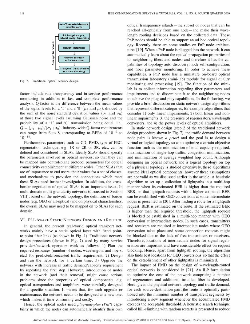
In general, the present real-world optical transport net-works mainly have a static optical layer with fixed point-to-point fiber-links (as shown in Fig. 1). Traditional networkdesign procedures (shown in Fig. 7) used by many serviceproviders/network operators work as follows: 1) Plan therequired resources (number of nodes, wavelengths, and fibers,etc.) for predicted/forecasted traffic requirement; 2) Designand run the network for a certain time; 3) Upgrade thenetwork with increase in traffic demand/capacity requirementby repeating the first step. However, introduction of nodesin the network (and their removal) might cause seriousproblems since the properties of optical components, e.g.optical transponders and amplifiers, were carefully designedfor a specific situation. It means that, for each upgrade ormaintenance, the network needs to be designed as a new one,which makes it time consuming and costly.Hence, the optical nodes need plug-and-play (PnP) capa-
bility in which the nodes can automatically identify their own
optical transparency islands—the subset of nodes that can bereached all-optically from one node—and make their wave-length routing decisions based on the collected data. ThesePnP nodes should be able to support an ad hoc optical topol-ogy. Recently, there are some studies on PnP node architec-tures [19]. When a PnP node is plugged into the network, it canautomatically learn about the optical propagation properties ofits neighboring fibers and nodes, and therefore it has the ca-pabilities of topology auto-discovery, node self-configuration,and fiber parameter monitoring. In order to achieve thesecapabilities, a PnP node has a miniature on-board opticaltransmission laboratory (mini-lab) module for signal qualitymonitoring and processing [19]. The function of the mini-lab is to collect information regarding fiber parameters andimpairments and to disseminate it to the neighboring nodesto achieve the plug-and-play capabilities. In the following, weprovide a brief discussion on static network design algorithmsthat represent different categories, for example, algorithms thatconsider 1) only linear impairments, 2) both linear and non-linear impairments, 3) the presence of regenerators/wavelengthconverters, and 4) the power levels of optical amplifiers.In static network design (step 2 of the traditional network
design procedure shown in Fig. 7), the traffic demand betweennode pairs is known a priori and the goal is to design avirtual or logical topology so as to optimize a certain objectivefunction such as the minimization of total capacity required,maximization of single-hop traffic, congestion minimization,and minimization of average weighted hop count. Althoughdesigning an optical network and a logical topology on topof a physical topology is studied extensively, these algorithmsassume ideal optical components; however these assumptionsare not valid as we discussed earlier in the article. A heuristicalgorithm to set up a collection of lightpaths in a multi-hopmanner when its estimated BER is higher than the requiredBER, so that lightpath requests with a higher estimated BERcan be established with OEO conversions at some intermediatenodes is presented in [20]. After finding a route for a lightpathrequest, BER is estimated on the route. If the estimated BERis higher than the required threshold, the lightpath requestis blocked or established in a multi-hop manner with OEOconversion at intermediate nodes. In such cases, transmittersand receivers are required at intermediate nodes where OEOconversion takes place and some connection requests mightbe blocked due to the lack of free transmitters or receivers.Therefore, locations of intermediate nodes for signal regen-eration are important and have considerable effect on requestblocking. Hence, apart from lightpath routing, the algorithmalso finds best locations for OEO conversions, so that the effecton the establishment of other lightpaths is minimized.The impact of PMD on the design of wavelength-routed
optical networks is considered in [21]. An ILP formulationto optimize the cost of the network comprising a numberof regenerators and additional installed fiber is developed.Here, given the physical network topology and traffic demand,for each source-destination pair, the route is optimally parti-tioned into the minimum number of transparent segments byintroducing a new segment whenever the accumulated PMDexceeds the acceptable threshold. A heuristic search techniquecalled hill-climbing with random restarts is presented to reduce
Authorized licensed use limited to: Monash University. Downloaded on February 22,2010 at 22:37:10 EST from IEEE Xplore. Restrictions apply.
SARADHI and SUBRAMANIAM: PHYSICAL LAYER IMPAIRMENT AWARE ROUTING (PLIAR) IN WDM OPTICAL NETWORKS: ISSUES AND CHALLENGES 119
the complexity of the optimal solution and evaluated onnetworks with non-homogeneous fiber quality.For designing optical networks, three kinds of strategies
are proposed: the wavelength path (WP)—same wavelength isassigned on all the links along the path, the virtual wavelengthpath (VWP)—the wavelengths are assigned link-by-link andwavelengths can be changed at all intermediate OXCs, thepartial virtual wavelength path (PVWP)—only a limited num-ber of converters are placed in the OXCs. A very detailedcomparison of these three methods on Italian and Belgiannetworks with coherent wavelength converters in OXCs underPLIs is presented in [22] with a traffic matrix as input. Inthis study, only ASE and in-band crosstalk are consideredwith the assumption that there are no non-linear effects. Threeperformance metrics are considered for evaluating differentrouting methods: system scale (σ)—average number of OXCports which is the sum of average number of ports directedtoward other OXCs (σ1) and the average number of portsconnecting an OXC to the higher client layers of the network(σ2), wavelength conversion percentage amount (WCPA)—K/(σ1W ) where K is the average number of converters inthe OXC and W is the number of wavelengths in a fiber, andthe average unacceptable paths number (UPN)—after findinga route for a lightpath request, the Q-factor is estimated on theroute and the number of paths that do not assure acceptableQ-factor is considered as a metric. The results show that UPNis quite large in the case of VWP due to the large numberof wavelength converters crossed by each path. In addition, itis shown that the PVWP scheme achieves the same routingperformance as the VWP scheme, but with simpler OXCs andwith much better transmission performance.In [23] a simple impairment model is developed to es-
timate the goodness of a lightpath as given by OSNR =OSNRASE − OSNRpen,lin − OSNRpen,nl [dB], whereOSNRASE is the OSNR penalty due to ASE noise, andOSNRpen,lin and OSNRpen,nl are OSNR penalties dueto linear and non-linear PLIs, respectively. The penaltiesOSNRASE and OSNRpen,lin are estimated using modelsavailable in the literature. The OSNRpen,nl depends onthe number of wavelengths used in the fiber (i.e., logicalnetwork configuration) and is estimated considering XPM.However, both SPM and FWM are neglected. A series ofMonte-Carlo simulations are performed on a test-link andan empirical function for noise standard deviation σXPM =[PTXLeffγKlog(Nw)/Δfdmin] is deduced, where PTX isthe channels power, Leff is the effective length of the link,Δf is the minimum channel spacing, Nw is the total numberof established channels in the fiber, γ is the fiber non-linearcoefficient, dmin is the minimum distance between the channelunder consideration and the used wavelengths, and K isa constant used to fit the values given by XPM. Given aphysical topology and a set of lightpath requests, the RWAis posed as an optimization problem with the objective tomaximize the minimum OSNR among the lightpath requests.As the optimization problem is NP-complete, two greedyalgorithms—first-fit minimum hop (FF-MH), in which shortestpath and first available wavelength is used, and best-opticalsignal to noise ratio (B-OSNR)—which jointly chooses a pathand a wavelength solution which provides maximum OSNR;
and two metaheuristic algorithms—simulated annealing (SA)and Tabu search (TS) are developed. It is shown that FF-MHdoes not meet the minimum OSNR requirement and gives theworst results; B-OSNR improves the solution by 1 dB but doesnot meet the minimum OSNR requirement in all scenarios,whereas SA improves the solution by 2 dB and always meetsthe minimum OSNR requirement.The gain of an optical amplifier depends on the total
power of all the established channels on a fiber and getssaturated when it exceeds a certain threshold. One individuallightpath with high signal power might saturate the amplifierand reduce the gain for other lightpaths that are sharing thesame amplifier. Hence, for proper operation of lightpaths inthe network, the power level of individual lightpaths needsto be maintained such that total aggregated power of all thechannels on a fiber is maintained below a certain threshold.Given a physical network topology, set of amplifier locations,set of available wavelengths on each link, traffic matrix, andsystem parameter triple (Psen, Pmax, SSG), where Psen is thethreshold for power below which a signal cannot be detected;Pmax is the maximum aggregate power on a link, and SSG isthe maximum small-signal gain for an inline EDFA amplifier;the RWA with power constraints (RWA-P) is formulated asa mixed integer non-linear program (MINLP) with the ob-jective of maximizing the number of established connectionswithout violating (Psen, Pmax, SSG), while determining thetransmitted powers of lightpaths [24]. Since RWA-P is NP-complete, a two phase solution is proposed: in the first phase,RWA without power constraints using a fixed set of routes isformulated as an ILP problem and solved, and in the secondphase, power assignment to the source nodes is done usingeither a heuristic algorithm called smallest-gain first (SGF)or a genetic algorithm (GA). The results from simulationexperiments show that though GA takes more time to find agood solution, it performs well for a wide choice of networkparameters compared to SSG.
VII. PLI-AWARE DYNAMIC ROUTING: SINGLE-DOMAINCASE
Recently, there has been a lot of interest in the researchcommunity in addressing the issues raised by the opticallayer transparency and PLIs that are discussed earlier. Mostof the studies on PLIs have considered a subset of linearimpairments and their effects, as it is difficult to considerboth linear and non-linear PLIs and their dependencies. ThePLI-aware RWA algorithms available in the literature canbe classified based on 1) the constraints used to verify thefeasibility of a lightpath, such as OSNR, BER, Q-factor, 2)the impairments considered in the feasibility evaluation, 3)the type of RWA algorithm such as integrated—where routeand wavelength are calculated jointly in a single step — ortwo-step—where network route and wavelength are computedin two different steps one after the other, 4) the network scopesuch as centralized or distributed RWA, and 5) PLI scope—whether PLIs are estimated using analytical models either ina centralized server or in a distributed manner; or measuredin real-time using monitors.A more general flowchart of dynamic PLI-aware RWA
algorithms is shown in Fig. 8. Note that in Fig. 8, 1) the RWA
Authorized licensed use limited to: Monash University. Downloaded on February 22,2010 at 22:37:10 EST from IEEE Xplore. Restrictions apply.

120 IEEE COMMUNICATIONS SURVEYS & TUTORIALS, VOL. 11, NO. 4, FOURTH QUARTER 2009
Fig. 8. A general flow chart for PLI-aware RWA algorithms.
block is responsible for either integrated or two-step RWA and2) the lightpath feasibility test block is responsible for opticalfeasibility evaluation for a set of PLIs collected using eithercentralized or distributed approaches, wherein the PLIs may beobtained using either analytical models or real-time monitorsagainst some feasibility metric (e.g. OSNR, BER, etc.). Here,for each connection request a route and wavelength are foundusing a well-known RWA algorithm and then the lightpath istested for its feasibility. The RWA can be a two-step or single-step procedure. Then the OSNR/BER/Q-factor is estimatedon the selected lightpath using the PLI-modeling techniquespresented in Sections II-V. If the estimated OSNR/BER/Q-factor satisfies the threshold requirement, the lightpath isfeasible and is admitted into the network. Otherwise, RWAmay select an alternate route and/or wavelength and repeatthe procedure to check the feasibility of the selected routeand/or wavelength. For simplicity, trying alternate route and/orwavelength is not shown in Fig. 8.
A few studies considered the route computation first andthen the verification of the optical feasibility of the path [25-27]. In [25] an online BER calculation mechanism is pro-posed and integrated into existing RWA algorithms. For eachrequested call, the network layer finds a route and then theBER is estimated on free wavelengths using the physical layermodels and online BER calculation mechanism. A simulationstudy was conducted on ring and mesh networks and it wasfound that employing BER-based call admission algorithmshas a significant impact on the performance of real networks.In [26] two algorithms, namely, impairment-aware best-path(IABP) and impairment-aware first-fit (IAFF) algorithms areproposed. The network layer finds a shortest path and thenuses either best-fit or first-fit wavelength assignment techniqueto find a free wavelength. Once the route and wavelength arefound, both PMD and OSNR are estimated. If the estimatedPMD and OSNR both meet the requirement, then the lightpathis established and the request is accepted.The study in [27] considered non-linear impairments to-
gether with linear impairments and proposed two RWA al-gorithms based on two step procedure, namely, first-fit min-imum hop (FF-MH), first-fit least-congested (FF-LC) andone integrated algorithm called best optical signal to noiseratio (B-OSNR). In FF-MH, the shortest path is selected andfirst-fit wavelength assignment technique is used to find alightpath. But in FF-LC, a pre-ordered list of available paths is
dynamically sorted based on the wavelength usage informationand the least congested path is selected. The B-OSNR findsboth route and wavelength simultaneously but the complexitygrows linearly with number of routes and wavelengths.Some other studies have considered the estimated impair-
ments during the path computation and then the verification ofoptical feasibility [28], i.e., the link costs are assigned basedon analytically computed Q-factors (based on the impairmentinformation collected from the network design phase) and thenk-shortest paths are computed to solve a linear optimizationproblem to find the minimum cost lightpath. The lightpathis established if the Q-factor of the lightpath is above therequired threshold. Yet some other studies have consideredthe impairments during the network design phase [20-24, 29].In [29], CD and filter concatenation effects are consideredapart from PMD, ASE, and CT and an ILP formulation isdeveloped based on the three-step procedure in [28] for designof metro area networks. These studies assumed that the PLIsare static and are used to compute optical feasibility of thepath whereas, in fact, PLIs such as crosstalk and non-linearimpairments change dynamically based on the status of thenetwork. A rigorous analysis of all PLIs and their effects onWDM optical network performance should require simulationof the entire network for every possible configuration that theRWA algorithms may take into account, which might requiremillions of hours of computation time. Hence, most of thestudies have considered a subset of impairments separatelywithout considering their combined effects.In [30] a PLI-aware architecture based on GMPLS control
plane is developed. The extensions required to GMPLS controlplane are discussed in Section X. Table II presents a surveyof relevant work in the literature. The various definitions andcategories are as follows: the network scope—whether theRWA procedure is centralized or distributed; PLI scope—can be centralized where the impairments are assumed tobe available at a central server using analytical models ordistributed in which impairments are either disseminated usingOSPF-TE or collected using RSVP-TE or online monitors;feasibility constraints—can be one of the optical parametersused to measure the quality of transmission at the receivingend of lightpath such as BER, Q-factor, OSNR, etc; PLIsconsidered—the PLIs considered and their complexity, e.g.linear impairments or non-linear impairments, or both; RWAalgorithms—can be PLI-aware RWA using joint RWA orstep-by-step RWA or normal RWA followed by feasibilityevaluation. To the best of our knowledge almost all thesestudies concentrate on RWA in single domain optical net-works with implicit assumption of homogeneous and singlegranularity optical networks, i.e., all links carry same numberof wavelengths and all wavelengths support the same bitrate. In the next section, we discuss the issues of PLI-aware dynamic routing in multi-domain and multi-granularity(MDMG) networks.
VIII. PLI-AWARE DYNAMIC ROUTING: MULTI-DOMAINAND MULTI-GRANULARITY CASE
All-optical networks are capable of switching traffic atvarious granularities other than a wavelength, for example,
Authorized licensed use limited to: Monash University. Downloaded on February 22,2010 at 22:37:10 EST from IEEE Xplore. Restrictions apply.

SARADHI and SUBRAMANIAM: PHYSICAL LAYER IMPAIRMENT AWARE ROUTING (PLIAR) IN WDM OPTICAL NETWORKS: ISSUES AND CHALLENGES 121
TABLE IIA CLASSIFICATION OF PLI-AWARE RWA TECHNIQUES.
Author andReference
PLIs Considered FeasibilityConstraints
RWA Algorithms PLI Scope NetworkScope
Remarks
Ramamurthy etal. [25]
ASE, XT BER 2-steps: 1) Network layer; 2)Optical feasibility
Centralized Centralized Models are presented forEDFA and OXC. Only ho-mowavelength crosstalk isconsidered
Huang et al.[26]
ASE, XT, PMD OSNR, PMDseparately
ASE noise and noise due tomultipath interference is con-sidered
Cardillo et al.[27]
PMD, ASE, SPM,XPM, FWM
OSNR Offline computation of NLPLI impact
Martins-Filhoet al. [32]
ASE, amplifier gainsaturation, and wave-length dependent gainand loss
BER 2-steps: 1) Route based onlowest PLIs [32]/Q-factor[33]; 2) BER feasibility
The order of two steps isdifferent from [25-27]
Markidis et al.[33]
SPM, XPM, FWM,GVD, optical filtering,and jitter degradation
Extension of [28] consider-ing 2R regeneration and non-linear impairments for ultralong-haul networks
Kulkarni et al.[28], Tomkos etal. [29]
ASE, CD, PMD, XT,Filter concatenation
Q-factor 3-steps: 1) Link cost compu-tation; 2) Shortest path; 3)Optical feasibility
Traffic matrix is known a-priori
Duhovnikov etal. [31]
ASE, PMD, CD SRS,SPM, XPM, FWM
Q-factor 3-steps: 1) Q-factor for λ; 2)Linear constraints; 3) Modi-fied shortest path algorithm
Impact of LI+NLI computedoffline. Fixed span only
Martnez et al.[30]
ASE, CD, PMD NotSpecified
1-step: distributed route andwavelength computationbased on updated PLIinformation
Collectedon-line
Distributed Routing-based approach isused to carry impairment re-lated information.
Li et al. [34] ASE, fiber dispersion,and PMD
Q-factor 3-steps: 1) Link metric usingestimated ECP; 2) Shortestpath using Bellman-Ford; 3)Optical feasibility based onQ-factor
Collectedon-line
Distributed Proposed and evaluated analgorithm in the context ofASON
Pinart et al.[35]
ASE, PMD OSNR,PMD, andOSNR-PMD
2-steps: 1) Optical-layer linkparameter monitoring; 2)PLIAR computation
Collectedon-line
Distributed Proposed a technique to ag-gregate PLIs to reduce rout-ing information
Pavani et al.[36]
ASE Min/max sig-nal power
3-steps: 1) Routing basedon fixed-alternate routing; 2)First-fit wavelength assign-ment; 3) Min/max powerconstraint check
Centralized Centralized Maximum (minimum) powerconstraint is used to limitthe non-linear PLIs (to as-sure minimum OSNR)
Papadimitriouet al. [37]
SPM, XPM, FWM Non-LinearPhase Shift
OSPF-TE used to distributenon-linear phase shift andcompute routes. RSVP-TE isused to set up lightpaths
Distributed Distributed SBS and SRS are assumed tobe handled at design phase
McNeill et al.[38]
ASE, CD, PMD,SPM, XPM, FWM
Q-factor 2-Step process: 1) Route se-lection; 2) Wavelength selec-tion
Distributed Distributed Architecture and variousdatabases required toimplement continuousOPM, feedback, and ICBRare presented. Effect ofimpairments on variousmodulation formats isstudied
Tomkos et al.[39]
ASE, XT, FWM,XPM
Q-factor 3-Step process: 1) Pre-processing phase collectsall the information aboutthe network/traffic demandsand assigns Q-factor aslink cost; 2) A jointoptimization problem withk-shortest paths is solved;3) Feasibility constraint onQ-factor is checked
Centralized Centralized For calculating Q-factor ofa k-link path, an empiricalformula is presented
Politi et al. [40] FWM, XPM, OSNR Q-factor 2-Step process: 1) Path selec-tion based on least conges-tion; 2) Wavelength selectionbased on best physical per-formance
Centralized Centralized An analytical model is pre-sented to compute Q-factorbased on several impair-ments
Authorized licensed use limited to: Monash University. Downloaded on February 22,2010 at 22:37:10 EST from IEEE Xplore. Restrictions apply.

122 IEEE COMMUNICATIONS SURVEYS & TUTORIALS, VOL. 11, NO. 4, FOURTH QUARTER 2009
TABLE II (cont.)A CLASSIFICATION OF PLI-AWARE RWA TECHNIQUES.
Author andReference
PLIs Considered FeasibilityConstraints
RWA Algorithms PLI Scope NetworkScope
Remarks
Politi et al. [41] FWM, XPM,OSNR
Q-factor 2-Step process: 1) Foreach wavelength computeshortest cost path; 2) Se-lect shortest cost path andsee if the Q-factor is abovecertain threshold for thecurrent and existing light-paths
Centralized Centralized Three cost metrics are con-sidered 1) length of the path,2) congestion of the path,and 3) noise of the channelin the path
Castoldi et al.[42]
ASE, PMD, CD,SPM using non-linear phase shift
BER + Q-factor witha relation toOSNR
Two different methods:Signaling based distributedmethod and PCE basedcentralized method.
CentralizedandDistributed
CentralizedandDistributed
A comparison of central-ized vs distributed RWA. Theconclusion is signaling ap-proach may require exten-sions while PCE based ap-proach may suffer from scal-ability problems
Deng et al. [43] ASE, fiberattenuation, OXCinsertion loss andOSNR degradation,receiver noise,and amplifier gainfluctuations
Receivedpower,OSNR, BER
Dynamic source power as-signment algorithm is pro-posed. Fixed shortest pathrouting is used. Upon callarrival 1)Assign minimumpower to the source andaccept the connection, ifOSNRr,x ≥ OSNRth
and Ps,rx ≥ Psen; 2)Otherwise central serverinitiates the source poweradjustment algorithm
Centralized Centralized Infinite number of wave-lengths is assumed. It re-quires all OXCs in the net-work to report their equaliza-tion status to central serverOSNRr,x − OSNR at thereceiver where OSNRth -OSNR threshold; Ps,rx -Received power; Psen - Re-ceiver sensitivity; Note thatthe power assignment is dif-ferent from RWA.
Deng et al. [44] ASE, linear in-bandcrosstalk in OXC,OSNR penalty dueto fiber non-lineareffects
Q-factor andBER
Two adaptive routingalgorithms proposed: 1)Q-measurement method(QM); 2) Adaptive QoSalgorithm based on QM
Q-factor iscollectedon-line
Centralized Standard control plane pro-tocols such as OSPF-TE isassumed to be present to dis-seminate Q-factor informa-tion
Pointurier et al.[45]
ASE, crosstalk,non-linear penalty,CD
Q-factor Compute the shortest pathfor each wavelength andcheck if Q-factor of cur-rent and existing lightpathsis above threshold. Se-lect one path that satisfiesthe above constraint usingone of the four proposedheuristics
Q-factor iscollectedon-line
Centralized Fairness is the main con-cern and to achieve fairnessamong blocking probabilityand BER four heuristics areproposed
packet/burst, waveband, fiber, and furthermore different wave-lengths may operate at different bitrates. Thus, it is likely thatfuture all-optical networks consist of multiple granularities.So, it is very important to examine the interfaces betweenthe different granularity layers within the all-optical network,for example, would a wavelength layer and a waveband layeroperate in a peer-to-peer arrangement or in a client-servermode? Even if the switching granularity is the same, it maybe the case that different links have different physical layertechnologies making them heterogeneous networks, for exam-ple some links may employ DWDM technology and someothers may use CWDM technology. The spacing between thewavelengths may be different or the type of transceivers usedmay be different. Furthermore, future optical networks mostlikely will have several domains each controlled by a differentservice provider and the granularity within each domain maybe different.Given all these, it is natural that in the future, all-optical
networks will be multi-domain multi-granular (MDMG) andit is important to understand how various PLIs affect service
provisioning in these networks. Though there are many def-initions of domain and granularity, in this article we restrictthe definition of domain and granularity to the following. Wedefine a domain as an independently managed network cloudexposing a set of ingress and egress nodes and links. Inside adomain the paths from a node to any other node may or maynot be optically feasible. The separation between neighboringdomains can be either OEO nodes or all-optical switches witha few ports shared between different domains. We call theseswitches (irrespective of whether the switch is optical or O-E-O) as border switches. Ports on border switches can terminatelinks of multiple different domains. Every border switch needsa globally unique address or name for addressing purposes.Based on the design of the optical network and the type of
border switches, there is a possibility of having several kindsof MDMG networks. For example, we can design all-opticalsub-networks (optical islands) such that any route is physicallyfeasible and the border switch is equipped with transponderinterfaces, where the signal undergoes electrical conversion[46-51]. This design is simple and straightforward and can
Authorized licensed use limited to: Monash University. Downloaded on February 22,2010 at 22:37:10 EST from IEEE Xplore. Restrictions apply.

SARADHI and SUBRAMANIAM: PHYSICAL LAYER IMPAIRMENT AWARE ROUTING (PLIAR) IN WDM OPTICAL NETWORKS: ISSUES AND CHALLENGES 123
be used for static and dynamic optical networks, but is sub-optimal. The connection set-up algorithm is also very simple,since it does not consider physical constraints. In the secondtype of design, the border switch may not be OEO capable;instead it is an optical switch some ports of which are ownedby one domain and some other ports are owned by otherdomain(s). In the third alternative, a network domain couldhave been designed without considering any impairments atall, but could have provisions for OEO conversion at somepoints in the network. In this case, the control plane shouldbe intelligent enough to consider impairments when selectingroutes and wavelengths. Other types of network design couldbe such that some connections are physically feasible betweenevery pair of nodes. In this case, we need to find a series oflightpaths to be cascaded between a source and destination.The complexity of information exchanged between domains
and RWA depends on the type of border switch, typically,OEO or all-optical switch. However, in general the borderswitches are OEO in order to reduce the overall complexity.The presence of all-optical border switches requires standard-ization of wavelength spacing, optical power, and may needefficient alien wavelength monitoring techniques as discussedin Section XII. The requirement for routing in a MDMGnetwork (in case of OEO border switches) is that the RWAprocess needs to know the extent of each domain and thegranularities on each link within the domains. There areseveral reasons for this [46, 47]:
1) When entering or leaving an all-optical domain, theregeneration process cleans up the optical impairmentsdiscussed in Section I. If the domain is not an all-optical domain, the routing process needs to computea path which is physically feasible and also satisfies thebandwidth requirement considering the granularities ofdifferent links using some kind of constrained shortestpath first (CSPF) algorithm.
2) Each domain may have its own bounds on each of thePLIs and inter-domain routing process needs to meetthese requirements apart from meeting the overall PLItarget.
3) The routing process needs to be sensitive to the costsassociated in traversing through other domains withmultiple granularities. Some domains may not supportthe higher granularities (for example, 40 G interfaces).In this scenario, though there may exist routes fromthe source to the destination through multiple domains,the interface granularities in various domains may notsupport the connection.
The issues raised above have some implications on standardGMPLS control plane and are discussed below:
1) Information about each domain and their boundariesneeds to be advertised (PLI information may need tobe advertised in some cases). Granularity informationcan be obtained using some directory services as it ismore often static information.
2) The routing algorithm needs to be sensitive to domaintransition and to the connectivity and granularity limi-tations and PLI constraints particular to each domain.
3) The cost function used in routing must allow the bal-
ancing of transponder costs, OXC and OADM costs, andfiber costs across the entire routing domain.
The topology and PLI information can be advertised in sev-eral ways. When a domain advertises its topology informationto other collaborating domains, it is not necessary to includethe details such as internal switches and internal links. Instead,it will just send out a topology summary of its own domainconsisting of only border switches and abstract links. A peer-to-peer publish/subscribe based routing protocol to exchangetopology summaries among different domains can be used.The peer-to-peer exchange mode may be more suitable thansimple flooding because it is possible that some domains maywant to selectively advertise different sets of resources todifferent domains.In a second method, the routing process can advertise the
internal topology including granularities and PLI constraintsof each domain globally. This method allows the ingress nodeto compute an end-to-end strict explicit route considering con-straints such as granularity, PLI, and wavelength availabilities.In this approach, the routing algorithm used by the ingressnode must be able to deal with the details of routing withineach domain.In a third method, when a lightpath reservation request ar-
rives, the local domain will compute a domain-level path basedon its own view of global topology. This path includes onlythe border switches. Source routing will be used to computethe path. Then the border switches can be requested to getthe route within the next domain, if the complete topologyinformation of all the nodes is not present with the sourcenode. In this method, impairment and granularity constraintsare handled within each domain and are not required to beadvertised outside of the domain. The methods discussedhere are not extensively studied in literature. It needs an in-depth study to understand the issues involved and to arriveat efficient methods for routing in PLI-aware MDMG opticalnetworks.It is worth to note that disseminating a huge amount of
information across the domain borders is either difficult orintroduces a lot of overhead. The overhead can be reducedusing TE aggregation or optical layer aggregation. However,the aggregation either requires huge processing and advertisingoverheads to keep it up-to-date, or results in the loss ofinformation that may result in path computation based on theaggregation useless. Recently, the Internet engineering taskforce (IETF) standardization body proposed a path computa-tion element (PCE) [52, 53] based approach to solve multi-domain path computation issues. PCE is an entity/applicationthat can run on network node/component or on out-of-networkserver and is capable of computing a constrained route foran incoming connection request based on a network graphobtained through Traffic Engineering Database (TED). PCE-based path computation is applicable in intra-domain, inter-domain, and inter-layer (e.g. IP over DWDM) contexts. Pathcomputation can be realized via single PCE or through mul-tiple PCE entities. The computational model used to computea route can be centralized or distributed: in the first case, onlya single PCE is involved in the path computation, while inthe latter either single or multiple PCE path computations
Authorized licensed use limited to: Monash University. Downloaded on February 22,2010 at 22:37:10 EST from IEEE Xplore. Restrictions apply.

124 IEEE COMMUNICATIONS SURVEYS & TUTORIALS, VOL. 11, NO. 4, FOURTH QUARTER 2009
Fig. 9. Flow chart for PLI-aware wavelength assignment scheme.
can be performed. Though PCE is targeted to address severalpath computation issues in multi-domain networks, it is notaware of physical layer constraints that are specific to opticalnetworks and needs corresponding techniques and extensions.
IX. PLI-AWARE WAVELENGTH ASSIGNMENT
In optical networks, the lightpath setup is done eitherusing integrated RWA considering PLIs or in two steps:calculate CSPF and assign a wavelength. In the earlier partof this article, we argued the need for the route computationpart to be aware of the PLIs, however, careful selection ofwavelengths during RWA process can also reduce the impactof PLIs. There exist a few studies on physical layer awarewavelength assignment [54-58] techniques. A general flowchart for PLI-aware wavelength assignment is shown in Fig.9. For example, the in-band crosstalk has been consideredas a major impairment that significantly affects BER. Suchcrosstalk usually occurs when multiple lightpaths occupyingthe same or adjacent wavelengths pass through an opticalcross-connect. We can cleverly choose a wavelength basedon the ongoing wavelength usage in a cross-connect, whichcan actually reduce the crosstalk (thereby BER) and hence theimpact of impairments on optical feasibility [54-58].Two wavelength assignment schemes considering the im-
pact of FWM were proposed in [54], namely, greedy allocationand global allocation. In greedy allocation, the crosstalkgenerated by the calls in progress is considered only on thecandidate wavelength. But in global allocation, in additionto the crosstalk generated on the candidate wavelength, thecrosstalk generated on the active connections in the networkis also considered. In [55], several wavelength assignmenttechniques, namely, crosstalk aware (CTA)-random pick, CTA-first-fit, CTA-most-used, CTA-least-used, based on traditionalwavelength assignment schemes are developed. Here, all the
proposed schemes select a wavelength that creates as little in-band crosstalk on the new and existing lightpaths as possibleto reduce the number of BER-related blocked calls. Based onsimulation results, it is recommended that these algorithms beapplied to moderate to large scale networks such as MAN andWAN networks, where BER performance is critical.In [56], a wavelength ordering technique (FFWO, first-
fit with wavelength ordering) to overcome the crosstalk in-troduced by adjacent channels is presented. FFWO uses thefirst available wavelength in a specific predefined order. Thewavelength ordering is pre-computed offline once and staysstatic during network operation, and is explicitly designed tominimize the crosstalk due to adjacent wavelength usage. Thealgorithm for ordering wavelengths chooses wavelengths thatare not adjacent to any previously used wavelengths. If such awavelength does not exist, a wavelength that has one adjacentused wavelength is selected. Here, the route is computed usingminimum shortest path algorithm. It is shown that the blockingprobability using FFWO technique approaches that of PLI-aware wavelength assignment techniques [55], but with lowercomplexity.A wavelength assignment technique based on first-fit wave-
length spectrum separation (FFWSS) is presented in [57];again, it ignores non-linear fiber crosstalk yet works well whenPLIs are severe or moderate; if the PLIs are small, the blockingrate of FFWSS is worse than that of FFWO because it has aworse network-layer performance [57]. During the lightpathsetup procedure, the FFWSS algorithm tries to find the leastphysically impaired (performance penalty factor) channel andhence spreads the traffic to all wavelengths. The idea behindFFWSS is that the channels with the smallest total penaltyfactor are the least likely to be blocked because of an unsatis-factory BER. However, it adds a small amount of calculationcompared to the FFWO algorithm. An adaptive wavelengthassignment technique based on wavelength spectrum separa-tion integrating non-linear crosstalk into the model of [57] ispresented in [58]. An adaptive switch function is integratedinto FFWSS to choose between FFWO and FFWSS basedon network PLI severity, to exploit the combined advantages,i.e., it exploits the strong node crosstalk rejection capability ofFFWSS in times of heavy instantaneous network usage whileenjoying the lower blocking rates of FFWO in times of lightnetwork usage.
X. PLI-AWARE CONTROL PLANE EXTENSIONS ANDSTANDARDIZATION
A recent approach to network control and managementusing the GMPLS framework [17] developed by IETF seemsto be emerging as the winning control plane solution for thenext-generation optical network. One of the main applicationsof GMPLS in the context of optical networks is the dynamicestablishment of lightpaths. However, it suffers from a lack ofphysical layer details such as PLI, transponder characteristicsand availability, regenerator/wavelength converter availabilityinformation, etc. The availability of this information makesa GMPLS-capable node capable of evaluating the effects ofPLIs and of deciding whether a proposed path is feasible in theoptical domain. In addition, GMPLS also suffers from the lackof good techniques to disseminate and utilize physical layer
Authorized licensed use limited to: Monash University. Downloaded on February 22,2010 at 22:37:10 EST from IEEE Xplore. Restrictions apply.

SARADHI and SUBRAMANIAM: PHYSICAL LAYER IMPAIRMENT AWARE ROUTING (PLIAR) IN WDM OPTICAL NETWORKS: ISSUES AND CHALLENGES 125
details. Hence, there is a strong need for the development ofefficient techniques to address these issues, without which itwould be impossible to automatically initiate a lightpath fromclient layers, for example, a router.In addition, control plane protocols need several extensions
to make them aware of PLIs. This can be done in one of threeways: the first option is to extend the routing protocol (forexample some interior gateway protocol (IGP) protocols suchas open shortest path first with traffic engineering extensions,OSPF-TE or intermediate-system to intermediate-system, IS-IS) to carry the wavelength availability and PLI information[59, 60]. In this case, the route is computed using a constrainedshortest path first (CSPF) algorithm at the source node anda wavelength is selected as well. The constraints used inthe CSPF algorithm can be extended to consider PLIs andhence no modifications are required for the signaling protocol(such as resource reservation protocol, RSVP-TE), to checkoptical feasibility. In order to consider this option, the PLIsat each node in the network need to be modeled consideringseveral possible types of network elements and vendors. Theimportant issues are: 1) to identify a subset of importantparameters that are to be carried in the routing protocol, 2) howto represent and carry these linear/non-linear impairments, and3) handling inaccurate wavelength availability/PLI informationdue to delays in link state advertisement (LSA) updates andnon-zero convergence time, which may result in an infeasiblelightpath. Hence, efficient techniques to handle network mis-alignments need to be explored. In addition, the stability ofthis method depends on the dynamics of traffic and the rateat which PLIs change.The second option is to extend the signaling protocol such
as RSVP-TE [60, 61]. In this method also, the route computa-tion is done at the source node using a CSPF algorithm. ThenRSVP-TE is used to select an optically/physically feasiblewavelength before setting up a lightpath. In this method, thereis no need to extend routing protocols (such as OSPF-TE or IS-IS), as RSVP-TE is used for physical/optical feasibility check.Hence, the impact of the dynamic traffic and the rate at whichPLIs change do not matter. The issues here are: 1) opticalfeasibility checking of bi-directional paths and the asymmetricnature of non-linear impairments in both directions, and 2)the selection of a suitable wavelength that minimizes theblocking of future connections and also the interference withthe existing lightpaths in the network.The third option is to extend both the signaling (RSVP-TE)
and routing protocols (OSPF-TE or IS-IS), where appropriate,depending on the complexity and feasibility considerations.For example, 1) the routing protocol can be extended to dis-tribute wavelength availability information, while the signalingprotocol can be extended to carry impairment-related infor-mation and check the feasibility of lightpath as in signaling-based approach, or 2) the routing protocol may be extendedto carry both wavelength availability information and linearimpairment information as these are relatively static in nature,while the signaling protocol carries non-linear impairmentinformation and evaluates the feasibility of lightpath duringthe setup phase. There are also some arguments to extend thelink management protocol (LMP) to carry and disseminate PLIinformation [62].
As discussed earlier in this section, the constraint-basedpath computation is a fundamental building block for trafficengineering in GMPLS-based optical networks. Path com-putation in large multi-domain, multi-region, or multi-layernetworks may require special computation components, suchas path computation element (PCE) and is emerging as anew standard from IETF [52, 53, 66-68]. In this approach thepath computation can be either centralized or distributed. In[68] the centralized path computation approach together withdistributed signaling to set up the paths is implemented andevaluated. In this approach, the PCE is aware of the completenetwork topology, resource availability, and physical param-eters in a central repository termed the traffic engineeringdatabase (TED). Since all the paths within the domain arecomputed by the PCE, lightpath provisioning both optimizesthe resource utilization and guarantees a required level ofoptical signal quality. In [34], an algorithm for path selectionin automatically switched optical networks (ASON) basedon eye closer penalty (ECP), Q-factor, and modified OSPFprotocol is presented. Through simulations, it was shownthat ECP caused by various impairments can be combinedapproximately linearly on dB scale. The estimated ECP is usedas a cost metric in OSPF using Bellman-Ford algorithm. Then,the Q-factor is used as a measure of signal quality to decideon the feasibility of the computed lightpath.Several common practical/deployment problems to all the
protocol extensions discussed above are: 1) downward com-patibility issues, i.e., what happens if there exist some nodeswhich are not aware of the proposed extensions? How tohandle these kinds of situations; 2) migration path—what isthe best strategy to replace or deploy the proposed extensionsin real-world networks; 3) fragmentation—after extensions,the length of the control packets (for example LSA) shouldnot exceed the maximum transfer unit (MTU) size leadingto IP fragmentation, which is a challenging issue to tackle;4) scalability—how the performance of these protocols varieswith the number of wavelengths (which may go beyond afew hundreds) and size of the control plane network; 5) bi-directional lightpath setup—is important to consider in thepresence of non-symmetrical PLIs and end components; 6)handling tunable components—how to handle the presence oftunable components such as, for example, tunable dispersioncompensators, 7) how to deal with non-linear impairmentswhich vary depending on network status and active adjacentchannels, and 8) others—the routing protocols are basicallydesigned to carry and disseminate only the routing informa-tion, which is much more static except in case of failuresor node additions/deletions. The proposed protocol extensionsmay add the wavelength availability and optical signal qualityor PLI information, making them dependent on the trafficpattern and thus more dynamic.There is also a strong need to design and assess various
control plane techniques/algorithms and extensions to han-dle the presence of regenerators/wavelength converters whileconsidering both linear and non-linear PLIs as discussed inSection XII.A. In addition to the issues discussed above,how do we disseminate the routing and PLI informationacross the domains? The inter-domain routing protocol suchas border gateway protocol (BGP) would need to be extended
Authorized licensed use limited to: Monash University. Downloaded on February 22,2010 at 22:37:10 EST from IEEE Xplore. Restrictions apply.

126 IEEE COMMUNICATIONS SURVEYS & TUTORIALS, VOL. 11, NO. 4, FOURTH QUARTER 2009
to disseminate this information or the standardization bodiessuch as IETF should try to come up with new generalizedmulti-protocol label switching (GMPLS) protocols to supportthis functionality. There is some work on optical BGP (OBGP)and asynchronous transfer mode (ATM) private network tonetwork interface (PNNI) for optical networks [63-65] withoutconsidering optical layer impairments.Control Plane API Standardization: Recently, there are
some discussions across various optical equipment vendors torun control plane software outside their equipment/hardware[69, 70]. In such cases, the control plane application programinterfaces (APIs) to the hardware need to be standardized.Different vendors may have different proprietary internalswitch architectures (for example, blocking or non-blocking,shared memory access, input buffer or output buffers, etc.),internal communication protocols, internal representations ofswitch configuration matrix, and modeling and representa-tion of PLIs. In order to run the control plane outside theequipment/hardware, at least some of these also need tobe standardized and need further investigation and researchefforts.
XI. PLI-AWARE FAST FAILURE RECOVERY ALGORITHMS
Maintaining a high level of service availability at an ac-ceptable level of overhead is an important issue in WDMoptical networks due to the huge volume of traffic carried insuch networks. Almost all protection/restoration mechanismsavailable in the literature assume the presence of an idealphysical layer, i.e., the existing methods did not consider theeffect of PLIs. Usually, the protection paths are longer thanthe primary/working paths. Hence, the protection/backup pathselection should introduce new constraints such as “impair-ments in the protection paths should be less than or equal tothe threshold value”. Introducing new constraints will makeit difficult to find an end-to-end protection path for a givenworking path, thereby leaving room for further research [71,72]. Usually, fault detection and localization is handled atthe optical layer, for example, by detecting the loss of light(LOL) on a WDM channel or an incoming fiber in an opticalswitch (i.e., OADM or OXC). When a connection traversesan excessive number of hops, the performance parameterssuch as OSNR and BER may be degraded, which couldcause a false LOL alarm to higher layers. Hence, failuredetection and localization algorithms need to be smart enoughto distinguish between real failures and poor performancedue to PLIs. In addition, failure recovery algorithms shouldconsider what happens after a failure. For example, failureoccurrences can cause rerouting of traffic, thereby introducingsudden changes in the channel load over the optical amplifiersalong the relevant links forming the protection path. This, inturn, could affect the normal operation of lightpaths that arerouted through the protection path before failure. Impact ofthese transient effects in an optical amplifier and the amplifierchain on the performance of the surviving channels needsfurther study.In multi-layer networks, a failure event changes the con-
figuration of the network, triggering recovery at multiplelayers. For example, in GMPLS/DWDM networks a failuretriggers recovery in both the optical domain and the GMPLS
control plane. The coordination or interworking aspects ofsingle layer recovery mechanisms is a challenging problem,specifically, for high-bandwidth DWDM networks which mayrequire guarantees on fast failure recovery, e.g. 50 msec.Failure recovery can be done either sequentially or in parallel.In the sequential case, failure recovery is handled at the opticallayer first; if it is not successful then the failure is propagated(escalated) to the GMPLS control plane. In the parallel case,failure recovery is triggered by both the optical layer andthe GMPLS control plane. The failure recovery at GMPLScontrol plane requires several details from optical layer, e.g.available wavelengths on links, the current network status interms of active channels on each link to evaluate the opticalfeasibility, etc., and techniques to handle transient effects dueto multiple concurrent restoration requests. These coordinationand interworking aspects require a more in-depth study tounderstand the requirements and to develop possible solutions.
XII. OTHER IMPORTANT ISSUES IN PLI-AWARE ROUTING
In this section, we discuss the importance of consideringPLIs in the development of various regenerator placementalgorithms, techniques to identify and mitigate optical layersecurity threats, grooming algorithms, and consideration ofpolicies and priorities in RWA algorithms.A) Regenerator Placement: Translucent optical network
design and placement of regenerators are particularly impor-tant in the context of IPoDWDM networks, due to increaseddemand for high-bandwidths from geographically distant lo-cations. The high-bandwidth requirement makes optical net-working vendors build high-bit-rate transponders and increasethe number of wavelength channels by reducing wavelengthspacing; both these activities lead to more vulnerability oflightpaths to PLIs and reduction of optical reach. In addition,transparent optical networks suffer from inefficient wavelengthutilization, as a connection request may be rejected because ofnon-availability of a common wavelength on all the links alongthe chosen route. To increase optical reach, resource utiliza-tion, and average call acceptance ratio (and hence revenues),network operators resort to regenerators. However, as OEOregenerators are expensive, operators are forced to reduce thenumber of regenerators in the network, and hence CAPEX,without compromising network performance. To address theseissues, recently there is a lot of interest in efficient regeneratorplacement [73-77].Efficient heuristics based on K-connected K-dominant sets
method is developed for placement of regenerators to guaran-tee K-connectivity [73]. In [74] the problem of establishinglightpaths in a multi-hop manner considering a subset ofimpairments is considered. A minimum cost solution usingdynamic programming (DP) and heuristic algorithms are pre-sented. These algorithms use BER for feasibility evaluationand try to reduce the overall cost of the network. In [75]the placement of regenerators in WDM ring networks understatic traffic is considered and three heuristic techniques areproposed, namely, genetic algorithms (GA), simulated anneal-ing (SA), and tabu search (TS) to solve the combinatorialoptimization problem. In [76] the advantages of using regen-erators in which the directionality can be changed dynamically,is studied and it is shown that the new architectures lead
Authorized licensed use limited to: Monash University. Downloaded on February 22,2010 at 22:37:10 EST from IEEE Xplore. Restrictions apply.
SARADHI and SUBRAMANIAM: PHYSICAL LAYER IMPAIRMENT AWARE ROUTING (PLIAR) IN WDM OPTICAL NETWORKS: ISSUES AND CHALLENGES 127
to significant savings in overall cost. In [77] a heuristic toachieve a given blocking probability with a minimum numberof regenerator nodes is proposed.The development of optical control plane and optical
components/sub-systems which are aware of PLIs, locationand number of regenerators/wavelength converters, is ofparamount importance for on-demand lightpath provisioning.Recently, handling regenerators using extended GMPLS con-trol plane, specifically RSVP-TE, under a specific set ofassumptions is addressed [78, 79]. However, [78, 79] does notconsider the full set of PLIs and availability of transponders.The proposed distributed regenerator selection methods take alonger time to set up a lightpath due to the two-step process:in the first phase it attempts to use transparent paths and if itis not successful then the algorithm tries to use regenerators.Efficient distributed techniques/algorithms for selection ofregenerators to reduce the cost of feasible connections, futureblocking, and extensions based on real node/network modelsare required for deployment of GMPLS protocols.B) PLI-Aware Security: There can be several kinds of
physical-layer security threats in optical networks, such as ser-vice disruption, tapping, intrusion, injecting malicious wave-lengths, etc., [80-82]. Rapid and sensitive attack detection,localization, and identification of an attack or intrusion iscritical. This can be sometimes achieved with advanced andintelligent OPM techniques (power, spectrum, and opticaltime domain reflectometer). Service disruption (SD) preventscommunication or degrades QoS. Optical amplifiers are par-ticularly vulnerable to SD attacks, such as gain competitionin EDFAs. To avoid this, all-Raman amplified systems can beused. Tapping compromises privacy by providing unauthorizedaccess to data which may be used for eavesdropping or trafficanalysis. Fiber non-linearities can be used for tapping, such asXPM or FWM. Advanced modulation formats such as polar-ization shift key (PLSK) can be used to avoid eavesdroppingfrom neighboring channels. In addition, PLSK also reducesnon-linear effects such as SPM, XPM, and FWM, but it isvery sensitive to PMD and PDL.Depending on the type of inter-domain switch (OEO or
an optical switch without OEO), different kinds of securityissues exist. These risks depend on the level of trust betweennodes that exchange GMPLS control messages, as well as therealization and physical characteristics of the control channel.If the border switch is an optical switch without OEO conver-sion, then it is required to allow externally generated opticalsignals (called alien wavelengths) into the domain. The alienwavelengths may be improper wavelengths or with differentwavelength spacings, may not meet the required power levels,or may have impairments inconsistent with those assumedby the domain. These alien wavelengths may create layer 1(optical layer) security threats. Hence, there is an urgent needfor efficient alien wavelength monitoring mechanisms [83]. Ifthe border switch is an OEO node, then these threats may becontrollable to some extent by signal regeneration, wavelengthconversion and positioning in international telecommunicationunion (ITU-T) grid, and cleaning of PLIs. Another layer 1security threat is resilience in case of physical attack. Apossible solution could be to define all kinds of physicalthreats, and then, for each in-scope threat, shared risk link
groups (SRLGs) must be defined so that all the links that arevulnerable to the same threat are grouped together in a singleSRLG [5]. The effectiveness of this solution depends on thedefinition of SRLGs and the characterization of physical layerparameters.C) Impact of Increase in Network Capacity: There are
two general ways of increasing network capacity: increase thenumber of wavelengths supported on a fiber or increase thebit rate of each wavelength [84]. The emergence of 40/100Gsystems over the next couple of years looks inevitable dueto the rapidly growing number of broadband subscribers andthe increased use of 10G Ethernet. Though 4× 10G DWDMsystems can be used to achieve the same transport capacity,carriers prefer 40/100G because of tradeoff between cost andflexibility. However, the leap from 10G to 40/100G posesinteresting economical and technical challenges, most notably,how to cope with PLIs. In general, all kinds of PLIs whichpresent at lower bit rates will tend increase on inverse squarelaw, i.e., four fold increase in bit-rate reduces the tolerance toPLIs by a factor of 16. This leads to more rapid degradationof the optical signal for a given fiber length. These challengesresult in a severe toll on the reach of the system, impactthe complexity and economics of the solution, and requireconsiderable advances in compensation techniques.For example, at 40G the duration of an optical pulse is
25 picoseconds, which is more susceptible to CD (whichdistorts or stretches the optical signal) and increases theISI compared to at 10G. However, as CD is largely time-invariant, depends on the fixed characteristics of the fiber,and CD compensation techniques are well known, it doesnot present a major problem. However, PMD (which largelydepends on mechanical factors during fiber manufacturing andinstallation) is more significant and poses serious challenges at40/100G due to its non-deterministic nature as it varies withboth long-term factors such as seasons/temperature and short-term factors such as local vibrations and mechanical stress.PMD reduces the unregenerated span distance significantly.For example, assuming an equivalent 1 dB penalty and a PMDcoefficient of 0.5 ps/
√km, the unregenerated span distance
is 400 km at 10G whereas it is 25 km at 40G, which is muchless than the typical spacing between existing equipment (e.g.regenerators or amplifiers).Overall, 40G systems can be deployed by replacing 10G
line cards with 40G line cards which have spectrally efficientmodulation formats, advanced error correcting codes, andvariable dispersion compensation. Note that both 10G and40G signals can co-exist in the same network. At 100G PLIsare more severe; for example CD tolerance decreases to ahundredth of 10G systems’, PMD tolerance decreases to atenth of that of 10G systems, and OSNR requirement increasesby 10 dB. Consequently, 100G deployment requires severaladvances in multi-level modulation, adaptive CD compensa-tion, advanced FEC, and coherent detection.D) PLI-Aware Traffic Grooming: For the network provider,
it is much more efficient and cost-effective to aggregateor multiplex lower-rate clients into a single, higher-capacitywavelength channel either in the time-domain [85] or in theoptical-domain [86]. Electrical-domain aggregation techniqueshave been termed as traffic grooming, whereas optical-domain
Authorized licensed use limited to: Monash University. Downloaded on February 22,2010 at 22:37:10 EST from IEEE Xplore. Restrictions apply.

128 IEEE COMMUNICATIONS SURVEYS & TUTORIALS, VOL. 11, NO. 4, FOURTH QUARTER 2009
techniques are called as optical time division multiplexing(OTDM). The PLIs dictate the physical span of an all-opticalpath and hence the placement of OEO and grooming-capablenodes in the network. OEO nodes allow for better trafficgrooming and also reset PLIs. Therefore, the conventionaltraffic grooming techniques discussed in the literature [85]may not be very effective in the presence of PLIs. In [87,88] traffic grooming in the presence of PLIs is considered.The effect of PLIs on grooming algorithms varies with thecapacity of wavelengths under consideration, i.e., the effectof PLIs when grooming 10G wavelengths may be differentthan when grooming 40G or 100G wavelengths. As thetrend in optical networking is moving from 10G to 40G ormore, it is necessary to understand these effects before actualdeployment.E) PLI-Aware Policies and Priorities: In Section V, we
defined some important optical layer SLAs. In order to findroutes which meet these SLAs together with network layerSLAs, a cost metric which is a function of signal qualityparameters corresponding to the PLIs and link metric (e.g.distance, delay, bandwidth, or number of wavelengths etc.,)may have to be defined. Consider an example to understandthe importance of policies and priorities—a traffic demandbetween node A and node B can be satisfied by two physicalpaths, say X and Y . Now consider two scenarios: 1) path Xhas lower hop count but higher BER; path Y has a slightlyhigher hop count but lower BER, and 2) path X has lowerBER and hop count but has an OEO node along the path; pathY is all-optical path with lower BER, but higher hop count.In both the scenarios, the final path selection depends on thepolicies and priorities enforced within the domains.In [89], RSVP-TE protocol is extended to handle the
transponder parameters and availability at signaling time. It isargued that there is a need to intelligently select a transponderbased on the sensitivity and availability; and then two PLI-aware transponder selection policies: worst-first and best-firstare presented. The worst-first policy selects a less sensitivetransponder among the available transponders leaving the besttransponders to be used by the lightpaths that are affectedworst by the PLIs (e.g. longer hop lightpaths). The best-first policy selects highly sensitive transponders among theavailable transponders. Simulation results show that the worst-first policy performs better w.r.t. blocking probability.
XIII. CONCLUSIONS AND FUTURE RESEARCHDIRECTIONS
In transparent optical networks, PLIs incurred by a non-ideal optical transmission medium accumulate along an opticalpath and determine the feasibility or transmission quality ofthe lightpaths. If the received signal quality is not withinthe receiver sensitivity threshold, the receiver may not beable to correctly detect the optical signal, and hence thereserved resources and lightpath become useless. Therefore,it is important to understand 1) various important PLIs,2) their effect on optical feasibility, 3) analytical models,monitoring and mitigation techniques, 4) various techniquesto communicate PLI information to network layer and controlplane protocols, and 5) finally, how to use all these techniquesin conjunction with control and management plane protocols
to dynamically set up and manage optically feasible lightpaths.In this article, we discussed the importance of PLIs andsurveyed the related work. Efficient optical impairment andperformance monitoring techniques are required to realizethe design of dynamic PLIAR algorithms. We presented asurvey of several PLI-aware RWA algorithms available inthe literature. We discussed several important issues in staticand dynamic routing scenarios and argued the importanceof PLI-aware control plane extensions. The disseminationof the collected impairment information to all nodes in thenetwork is important in computing and establishing opticallyfeasible lightpaths. The routing and signaling protocols shouldbe able to find and establish a feasible optical path (i.e.,the route, fiber, wavelength, transponders, regenerators, etc.)which meets the required received signal quality, such asBER. In order to accomplish these, the standard GMPLScontrol plane protocols need extensions to make them awareof physical layer impairments. We also presented severalsecurity threats at the optical layer and argued the need foralien wavelength monitoring techniques. The importance ofPLI-aware failure recovery algorithms, regenerator placementalgorithms, traffic grooming algorithms, etc., was discussed.Finally, this article identified several important and chal-
lenging issues which need more research by the commu-nity to understand, propose and evaluate efficient solutions,and to extend and standardize the control plane protocols,implementation, and deployment scenarios. Some of theseopen issues are as follows. As no existing work considersall PLIs in the RWA process, future research should considerboth linear and non-linear impairments and at the same timeshould try to reduce the computational complexity due to PLIevaluation. Presence of regenerators/wavelength convertersposes several new challenges and need to be studied in depth.Efficient placement of regenerators to increase the opticalreach and average call acceptance ratio at minimum costunder dynamic traffic scenarios is a good problem to address.Efficient placement of monitors to perform online OPM/OIMand the techniques to integrate the measured values with RWAprocess is an emerging topic of interest. Rerouting of existingconnections to satisfy feasibility constraints (e.g. BER, Q-factor, OSNR) and load balancing could be an important area.PLI-aware control plane protocol extensions and related al-gorithms considering the presence of regenerators/wavelengthconverters or tunable components is another important area offuture research.Several large scale research efforts, for example DICONET
(www.diconet.eu), DRAGON (http://dragon.east.isi.edu), CA-NARIE CAnet4 (www.canarie.ca), NOBEL2 (www.ist-nobel.org), GEANT2 (www.geant2.net), FIND (www.nets-find.net), GENI (www.geni.net), EIFFEL (www.fp7-eiffel.eu),FIRE (http://cordis.europa.eu/fp7/ict/fire), etc., funded byleading government agencies across the world, are undertakento address some of the issues discussed in this article andto provide a test environment for future Internet research.On the industry side, many carriers are actively deployingmetro DWDM and plan to roll out several emerging serviceswith the introduction of dynamically reconfigurable IPoD-WDM network architectures. In addition they are lookingto develop novel interoperability mechanisms, through for
Authorized licensed use limited to: Monash University. Downloaded on February 22,2010 at 22:37:10 EST from IEEE Xplore. Restrictions apply.

SARADHI and SUBRAMANIAM: PHYSICAL LAYER IMPAIRMENT AWARE ROUTING (PLIAR) IN WDM OPTICAL NETWORKS: ISSUES AND CHALLENGES 129
example IPSphere consortium, to develop a new business layerindependent of control and data planes. Apart from IETFdefining extensions for PLI-aware intra- and inter-domainrouting, the optical internetworking forum (OIF) is playinga crucial role in interoperability trials and initiatives. Clearly,these newer research initiatives will play a crucial prove-inrole for emergent dynamically reconfigurable next-generationoptical network technologies, and their importance cannot beunderstated. Finally, the challenges identified in this articleneed further consideration in current and future researchprojects, without which it may be difficult to realize thedeployment of dynamically reconfigurable optical networks.
ACKNOWLEDGMENT
Chava Vijaya Saradhi would like to thank his colleagues,Andrea Zanardi, Elio Salvadori, and EU-IST DICONETproject partners for technical discussions and valuable inputs.His work was supported by EU-IST DICONET project fundedby European Commission. Suresh Subramaniam was partiallysupported by NSF Grant 0519911. The authors would like tothank the anonymous reviewers for their valuable suggestionsfor improving the organization of this article.
REFERENCES
[1] G. P. Agrawal, Fiber Optic Communication Systems. Wiley Interscience,1992.
[2] G. P. Agrawal, Nonlinear Fiber Optics. New York: Academic, 1989.[3] B. Mukherjee, Optical WDM Networks. Springer, 2006.[4] R. Ramaswami and K. Sivarajan, Optical Networks: A Practical Per-
spective. Morgan Kauffman, 2001.[5] J. Strand et al., “Issues for Routing in Optical Layer,” IEEE Commun.
Mag., pp. 73-91, 2001.[6] H. Zang et al., “A review of Routing and Wavelength Assignment
Approaches for Wavelength Routed Optical WDM Networks”, OpticalNetworks Mag., vol. 1, no.1, Jan 2000.
[7] A. Gumaste and T. Antony, DWDM Network Designs and EngineeringSolutions. Cisco Press, 2002.
[8] Polarization Dependent Loss Measurement of PassiveOptical Components, Application Note, Agilent Technologieshttp://cp.literature.agilent.com/litweb/pdf/5988-1232EN.pdf.
[9] C. C. Chien and I. Lyubomirsky, “Comparison of RZ versus NRZ PulseShapes for Optical Duobinary Transmission,” IEEE/OSA J. LightwaveTechnol., vol. 25, Issue 10, pp. 2953-2958, Oct 2007.
[10] S. P. Singh and N. Singh, “Non-linear Effects in Optical Fibers: Origin,Management and Applications,” Progress in Electromagnetics Research(PIER), vol. 73, pp. 249-275, 2007.
[11] X. Liu and Y. H. Kao, “Chirped RZ-DPSK based on Single Mach-Zehnder Modulator and its Nonlinear Transmission Performance,” IEEEPhotonic Technol. Lett., vol. 17, no.7, pp. 1531-1533, 2005.
[12] D. C. Kilper et al., “Optical Performance Monitoring,” IEEE/OSA J.Lightwave Technol., vol. 22, no. 1, pp. 294-304, Jan 2004.
[13] M. Teshima et al., “Performance of Multiwavelength SimultaneousMonitoring Circuit Employing Arrayed-Waveguide Grating,” IEEE/OSAJ. Lightwave Technol., vol. 14, pp. 2277-2285, Oct 1996.
[14] L. M. Lunardi et al., “Tunable Dispersion Compensation at 40-Gb/susing a Multicavity Etalon All-Pass Filter with NRZ, RZ, and CS-RZModulation,” IEEE/OSA J. Lightwave Technol., vol. 20, Issue. 12, pp.2136-2144, Dec 2002.
[15] S. Shuichi et al., “Field Trial of All-Optical 2R Regeneration in 40-Gbit/s WDM Transmission Systems with Optical Add/Drop Multiplex-ing,” IEICE Trans. Commun., vol. E88-B, no. 5, pp. 1927-1933, 2005.
[16] http://www.lightreading.com/document.asp?doc id=10593[17] A. Farrel and I. Bryskin, GMPLS: Architecture and Applications,
Morgan Kauffman, 2005.[18] M. Fawaz et al., “Service Level Agreement and Provisioning in Optical
Networks,” IEEE Commun. Mag., vol. 42, no. 1, pp. 36-43, 2004.[19] I. Cerutti et al., “Plug and Play Networking with Optical Nodes,” Proc.
IEEE ICTON 2006.
[20] J. Y. Youe and S. W. Seo, “An Algorithm for Virtual Topology Design inWDM Optical Networks under Physical Constraints,” Proc. IEEE ICC1999, vol. 3, pp. 1719-1723, 1999.
[21] M. Ali and L. Tancevski, “Impact of Polarization Mode Dispersion onthe Design of Wavelength-Routed Networks,” IEEE Photonics Technol.Lett., vol. 14, No. 5, pp. 720-722, May 2002.
[22] R. Sabella et al., “Impact of Transmission Performance on Path Routingin All-Optical Transport Networks,” IEEE/OSA J. Lightwave Technol.,vol. 16, no. 11, pp. 1965-1972, Nov 1998.
[23] G. Bogliolo et al., “Considering Transmission Impairments in RWAProblem: Greedy and Metaheuristic solutions,” Proc. OFC 2007.
[24] M. Ali et al., “Routing and wavelength assignment with power consid-erations in optical networks,” Computer Communications, no. 32, pp.539-555, 2000.
[25] B. Ramamurthy et al., “Impact of Transmission Impairments onthe Teletraffic Performance of Wavelength-routed Optical Networks,”IEEE/OSA J. Lightwave Technol., vol. 17, no. 10, pp. 1713-1723, Oct1999.
[26] Y. Huang et al., “Connection Provisioning With Transmission Im-pairment Consideration in Optical WDM Networks With High-SpeedChannels,” IEEE/OSA J. Lightwave Technol., vol. 23, no. 3, pp. 982-993, Mar 2005.
[27] R. Cardillo et al., “Considering Transmission Impairments in Wave-length. Routed Networks,” Proc. ONDM 2005.
[28] P. Kulkarni et al., “Benefits of Q-factor based Routing in WDM MetroNetworks”, Proc. ECOC 2005.
[29] I. Tomkos et al., “Performance Engineering of Metropolitan Area Opti-cal Networks through Impairment Constraint Routing,” IEEE Commun.Mag. (Optical Supplement), Aug 2004.
[30] R. Martnez et al., “On-line ICBR in a Transparent GMPLS Network: AReality Check,” WGN5: V Workshop in G/MPLS networks, Mar 2006.
[31] S. Duhovnikov et al., “Dynamic RWA for All Optical Networks UsingLinear Constraints for Optical Path Feasibility Assessment,” Proc.ECOC 2006.
[32] J. F. Martins-Filho et al., “Novel Routing Algorithm for Optical Net-works Based on Noise Figure and Physical Impairments”, Proc. ECOC2003.
[33] G. Markidis et al., “Impairment Constraint Based Routing in Ultra LongHaul Optical Networks Employing 2R Regeneration,” Proc. ICTON2006.
[34] J. C. Li et al., “Enabling ASON Routing via Signal Quality Metrics,”Proc. OFC 2006.
[35] C. Pinart et al., “On Using Optical-Layer Link Information Parametersin Distributed Impairment Constraint-Based Routing,” Proc. OFC 2006.
[36] G. S. Pavani et al., “Dynamic Routing and Wavelength Assignment withPower Constraints,” Proc. SBT 2004.
[37] D. Papadimitriou et al., “Non-linear Routing Impairments in WavelengthSwitched Optical Networks,” IETF Draft, Work in Progress, draft-papadimitriou-ipo-non-linear-routing-impairm-01.txt, Jul 2001.
[38] K. M. McNeill et al., “Supporting Optical Impairment Constrained PathSelection in the Intelligent Transparent Optical Networking,” ——
[39] I. Tomkos et al., “Impairment Constraint Based Routing in Mesh OpticalNetworks,” Proc. OFC 2007.
[40] C. Politi et al., “Physical Layer Impairment Aware Routing Algorithmsbased on Analytically Calculated Q-Factor,” Proc. OFC 2006.
[41] C. Politi et al., “Cross Layer Routing in Transparent Optical Networks,”Proc. OFC 2006.
[42] P. Castoldi et al., “Centralized vs Distributed Approaches for Encom-passing Physical Impairments in Transparent Optical Networks,” Proc.ONDM 2007.
[43] T. Deng and S. Subramaniam, “Source Power Management in Trans-parent Wavelength Routed Mesh Networks,” Proc. IEEE ICC 2004.
[44] T. Deng and S. Subramaniam, “Adaptive QoS Routing in DynamicWavelength-Routed Optical Networks,” Proc. Broadnets 2005.
[45] Y. Pointurier et al., “Fair QoS-Aware Adaptive Routing and WavelengthAssignment in All-Optical Networks,” Proc. ICC 2006.
[46] J. Strand et al., “Impairments and Other Constraints on Optical LayerRouting,” RFC 4054, May 2005.
[47] X. Yang and B. Ramamurthy, “Inter-Domain Wavelength Routing inthe Next-Generation Translucent Optical Internet Backbones,” OSA J.Optical Networking, vol. 3, no. 3, pp. 169-187, Mar 2004.
[48] A. Farrel et al., “A Framework for Inter-Domain Multiprotocol LabelSwitching Traffic Engineering,” RFC 4726, Nov 2006.
[49] A. Farrel et al., “Inter domain Multiprotocol Label Switching (MPLS)and Generalized MPLS (GMPLS) Traffic Engineering - RSVP-TE Ex-tensions,” IETF Draft, Work in Progress, draft-ietf-ccamp-inter-domain-rsvp-te-06.txt, Sep 2007.
Authorized licensed use limited to: Monash University. Downloaded on February 22,2010 at 22:37:10 EST from IEEE Xplore. Restrictions apply.
130 IEEE COMMUNICATIONS SURVEYS & TUTORIALS, VOL. 11, NO. 4, FOURTH QUARTER 2009
[50] J. P. Vasseur et al., “A Per-domain path computation method for es-tablishing Inter-domain Traffic Engineering (TE) Label Switched Paths(LSPs),” IETF Draft, Work in Progress, draft-ietf-ccamp-inter-domain-pd-path-comp-05.txt, Apr 2007.
[51] Y. Ayyangar et al., “Label Switched Path Stitching with GeneralizedMultiprotocol Label Switching Traffic Engineering (GMPLS-TE),” IETFDraft, Work in Progress, draft-ietf-ccamp-lsp-stitching-06.txt, Apr 2007.
[52] IETF RFC 4655: A Path Computation Element (PCE) Based Architec-ture, Aug 2006.
[53] IETF RFC 4927: PCE Communication Protocol (PCECP) SpecificRequirements for Inter-Area Multi Protocol Label Switching (MPLS)and Generalized MPLS (GMPLS) Traffic Engineering, Jun 2007.
[54] I. E. Fonseca et al., “Algorithms for FWM-aware Routing and Wave-length Assignment,” Proc. IEEE IMOC 2003, vol. 2, no. 2, pp. 707-712,Sep 2003.
[55] T. Deng et al., “Crosstalk-Aware Wavelength Assignment in DynamicWavelength-Routed Optical Networks,” Proc. Broadnets 2004, pp. 140-149, 2004.
[56] J. He and M. Brandt-Pearce, “RWA using Wavelength Ordering forCrosstalk Limited Networks,” Proc. OFC 2006.
[57] J. He and M. Brandt-Pearce, “Dynamic Wavelength Assignment usingWavelength Spectrum Separation for Crosstalk Limited Networks,”Proc. IEEE Broadnets 2006.
[58] J. He et al., “Adaptive Wavelength Assignment Using WavelengthSpectrum Separation for Distributed Optical Networks,” Proc. IEEE ICC2007.
[59] R. Martnez et al., “Challenges and Requirements for IntroducingImpairment-Awareness into the Management and Control Planes ofASON/GMPLS WDM Networks,” IEEE Commun. Mag., vol. 44, no.12, pp76-85, Dec 2006.
[60] E. Salvadori et al., “Distributed Optical Control Plane Architectures forHandling Transmission Impairments in Transparent Optical Networks,”IEEE/OSA J. Lightwave Technol., vol. 27, no. 13, Jul 2009.
[61] F. Cugini et al., “A Novel Signaling Approach to Encompass PhysicalImpairments in GMPLS Networks,” Proc. Globecom 2004.
[62] L. Lang et al., “Link Management Protocol (LMP),” RFC 4204, Oct2005.
[63] S. Sanchez-lopez et al., “PNNI Based Control Plane for AutomaticallySwitched Optical Networks,” IEEE/OSA J. Lightwave Technol., 2003.
[64] Optical BGP - http://obgp.canet4.net/.[65] M. Francisco et al., “Interdomain Routing in Optical Networks,” Proc.
SPIE/ACM/IEEE Opticomm, vol. 4599, pp. 120-129, 2001.[66] S. Dasgupta et al., “Path-Computation-Element-Based Architecture for
Inter-domain MPLS/GMPLS Traffic Engineering: Overview and Perfor-mance,” IEEE Network, Jul/Aug 2007.
[67] E. Oki and A Farrel, “Extensions to the Path Computation ElementCommunication Protocol (PCEP) for Route Exclusions,” IETF Draft,Work in Progress, draft-ietf-pce-pcep-xro-02.txt, Sep 2007.
[68] F. Cugini et al., “Implementing a Path Computation Element (PCE) toEncompass Physical Impairments in Transparent Networks,” Proc. OFC2007.
[69] www.juniper.net/company/presscenter/pr/2008/pr-080225.html[70] IPsphere: www.ipsphereforum.org/Files/IPSF R1 Spec2.pdf[71] X. Yang et al., “Survivable Lightpath Provisioning in WDM Net-
works under Shared Path Protection and Signal Quality Constraints,”IEEE/OSA J. Lightwave Technol., Apr 2005.
[72] Y. Zhai et al, “Performance of Dedicated Path Protection inTransmission-Impaired DWDM Networks,” Proc. IEEE ICC 2007.
[73] M. S. Davasini et al., “Regenerator Placement with Guaranteed Con-nectivity in Optical Networks,” Proc. ONDM 2007.
[74] S. W. Kim et al., “Regenerator Placement Algorithms for ConnectionEstablishment in All-Optical Networks,” Proc. IEEE Commun., vol. 148,issue. 1, pp. 25-30, Feb 2001.
[75] T. M. Chan et al., “Solving the Converter Placement Problem in WDMRing Networks using Genetic Algorithms,” The Computer Journal, vol.46, no. 4, pp. 427-448, 2003.
[76] K. Sriram et al., “Performance Comparison of Agile Optical NetworkArchitectures with Static vs Dynamic Regenerator Assignment,” Proc.Broadnets 2005.
[77] G. Shen et al., “Sparse Placement of Electronic Switching Nodesfor Low Blocking in Translucent Optical Networks,” OSA Journal ofOptical Networking, pp. 424-441, 2002.
[78] F. Cugini et al., “GMPLS Extensions to Encompass Shared Regenera-tors,” Proc. ECOC 2007.
[79] N. Sambo et al., “Lightweight RSVP-TE Extensions to Account forShared Regenerators in Translucent Optical Networks,” Proc. Photonicsin Switching 2007.
[80] M. Medard et al., “Attack Detection Methods for All-Optical Networks,”Proc. NDSSS 1998.
[81] G. Liu et al., “Resilience of All-Optical Network Architectures underIn-Band Crosstalk Attacks: A Probabilistic Graphical Model Approach,”IEEE J. Sel. Areas Commun., vol. 25, no. 4, Apr 2007.
[82] T. Deng et al., “Evaluation of Optical Amplifier Robustness againstCovert QoS Attacks in a Point-to-Point DWDM Link,” Proc. OFC 2005.
[83] D. Z. Chen, and M. F. Lane, “Emerging Network Need for AlienWavelength Management,” Proc. OFC 2007.
[84] J. Berthold et al., “Optical Networking: Past, Present, and Future,”IEEE/OSA J. Lightwave Technol., vol. 26, no. 9, pp. 1104-1118, May2008.
[85] Y. Lee and B. Mukherjee, “Traffic Engineering in Next-GenerationOptical Networks,” IEEE Commun. Survey and Tutorial, vol. 6 no. 3,pp. 16-33, Third Quarter 2004.
[86] T. Ohara et al., “160-Gb/s OTDM Transmission using Integrated All-Optical MUX/DEMUX with All-Channel Modulation and Demultiplex-ing,” IEEE Photonic Technol. Lett., vol. 16, Issue. 2, pp. 650-652, Feb2004.
[87] E. Salvadori and R. Battiti, “A Traffic Engineering Scheme for QoSRouting in GMPLS Networks Based on Transmission Quality,” Proc.ONDM 2004.
[88] E. Salvadori and R. Battiti, “Quality of Service in IP over WDM:Considering both Service Differentiation and Transmission Quality,”Proc. IEEE ICC 2004.
[89] C. V. Saradhi et al., “Physical Layer Impairment (PLI) Aware Transpon-der Selection Policies for GMPLS/WDM Optical Networks,” Proc. OFC2008.
Chava Vijaya Saradhi (M’03) received his MSdegree in computer science from the Indian Insti-tute of Technology (IIT), Chennai, India and thePh.D. degree from National University of Singa-pore, Singapore. He worked as a Project Associateat IIT, Chennai. He was with Phillips InnovationCenter, Bangalore, India, as Software Engineer in2002. He was with Institute for Infocomm Research(I2R), Singapore, from Sep 2002 to Dec 2006, asa senior research engineer. Where he is extensivelyinvolved in development of GMPLS-based optical
network test-bed and field trail activities. Currently, he is working withCreate-Net, Italy, on several industry and EU funded projects. He has over55 journal/conference articles. In addition to the technical credentials, Dr.Saradhi has an extensive track record of service to the broader technicalcommunity. For example, he served as co-chair for IEEE/Create-Net GOSP2005/2006/2008 workshops. He served as guest editor for well-received andtimely three special issues of the IEEE Commun. Mag. and a special issue ofIEEE Network Magazine. He has also served on TPC of many internationalconferences and as a reviewer for many leading journals/conferences. Hisresearch interests include optical networks, GMPLS networks, wireless sensornetworks, and real-time systems.
Suresh Subramaniam (S’95-M’97-SM’07) re-ceived the Ph.D. degree in electrical engineeringfrom the University of Washington, Seattle, in 1997.He is a Professor in the Department of Electricaland Computer Engineering at the George Wash-ington University, Washington, DC. His researchinterests are in the architectural, algorithmic, andperformance aspects of communication networks,with particular emphasis on optical and wirelessad hoc networks. Dr. Subramaniam is a co-editorof the books “Optical WDM Networks - Principles
and Practice” and “Emerging Optical Network Technologies: Architectures,Protocols, and Performance”. He has been on the program committees ofseveral conferences including Infocom, ICC, Globecom, OFC, and Broadnets,and served as TPC Co-Chair for the optical networks symposia at Globecom2006 and ICC 2007. He currently serves on the editorial boards of theIEEE/ACM Transactions on Networking, Optical Switching and Networking,and KICS Journal of Communications and Networks. He is a co-recipientof Best Paper Awards at the ICC 2006 Symposium on Optical Systems andNetworks, and at the 1997 SPIE Conference on All-Optical CommunicationSystems.
Authorized licensed use limited to: Monash University. Downloaded on February 22,2010 at 22:37:10 EST from IEEE Xplore. Restrictions apply.