IEEE 802.11a/b/g/n Manufacturing Test with the Agilent...
32
IEEE 802.11a/b/g/n Manufacturing Test with the Agilent N8300A Part 1: Introduction to a WLAN manufacturing test plan and theory of implementation Application Note Introduction This application note is one of a four part series of documents on IEEE 802.11a/b/g/n WLAN testing using the Agilent N8300A wireless networking test set.
Transcript of IEEE 802.11a/b/g/n Manufacturing Test with the Agilent...

IEEE 802.11a/b/g/n Manufacturing Test with the Agilent N8300A Part 1: Introduction to a WLAN manufacturing test plan and theory of implementation Application Note
Introduction This application note is one of a four part series of documents on IEEE 802.11a/b/g/n WLAN testing using the Agilent N8300A wireless networking test set.

2
Table of Contents
Introduction ............................................................................................................ 3 WLAN Technology and the N8300A .................................................................. 4
The challenge ................................................................................................................................. 4 Path to manufacturing .................................................................................................................. 4 Production automation for high demand .................................................................................. 4 Programming and applications ................................................................................................... 4
The Test Plan ......................................................................................................... 5 Test Setup .............................................................................................................. 7
Characterization of signals with the Autorange tool ............................................................. 8 IEEE 802.11n ................................................................................................................................... 8 Continuous wave (CW) ................................................................................................................ 8
Phase 1 – Transmitter Calibration (“TX Cal”) .................................................. 9 Crystal trim calibration ................................................................................................................. 9 IQ calibration .................................................................................................................................. 9 Power calibration........................................................................................................................... 9 Test procedure ............................................................................................................................. 10
Crystal trim calibration 10 IQ calibration 11 Power calibration 12
Phase 2 – Received Signal Strength Indicator (“RX Cal”) ...........................14 Test procedure ............................................................................................................................. 14
Phase 3 – Spectral Mask and Power Verification (“TX Verify”) .................17 Power verification ....................................................................................................................... 17 Spectral mask ............................................................................................................................... 17 Test procedure ............................................................................................................................. 17
Power verification 17 Spectral mask 18
Phase 4 – Receiver Sensitivity and Maximum Input Level (“RX Verify”) ..19 Test procedure ............................................................................................................................. 20
Phase 5 – Modulation Accuracy (“TX Quality”) ............................................21 Test procedure ............................................................................................................................. 22 EVM results and troubleshooting ............................................................................................ 25
References ............................................................................................................27 Glossary ................................................................................................................28 Appendix A: Loss Compensation Calculations ..............................................29 Appendix B: DUT Command List ......................................................................30

3
Introduction
This application note is one of a four part series of documents on IEEE 802.11a/b/g/n WLAN testing using the Agilent N8300A wireless networking test set. 1. IEEE 802.11a/b/g/n Manufacturing Test with the Agilent N8300A
Part 1: Introduction to a WLAN manufacturing test plan and theory of implementation
This application note features a typical WLAN manufacturing test plan for testing IEEE 802.11a/b/g/n format devices. The document provides background and theory on the test phases of an example test plan. This is useful for development and production engineers who wish to obtain an understanding of the key tests in manufacturing. The N8300A measurements are introduced at each test phase with pseudo code used to demonstrate how a test may be implemented with the device under test (DUT). After reading this application note, the engineer should be ready to progress to the implementation of a test plan and N8300A test code. 2. IEEE 802.11a/b/g/n Manufacturing Test with the Agilent N8300A
Part 2: Implementation of a WLAN test plan using SCPI programming This application note builds upon the pseudo code examples and test phases presented in Part 1 of the series by providing standard commands for programmable instruments (SCPI) scripts. This document is particularly useful for test and production engineers who wish to programmatically implement tests with a DUT. These examples are easily leveraged into any programming environment. 3. IEEE 802.11a/b/g/n Manufacturing Test with the Agilent N8300A
Part 3: Techniques for optimizing WLAN device testing Test speed is influenced by a range of variables including the DUT, test methodology, and the test instrumentation. Part 3 of the series presents test techniques, test methods, and programming recommendations that are aimed at optimizing speed. This document is aimed at engineers who want to optimize existing tests, or, aiming to obtain best practices for maximizing speed and efficiency of a new test plan. 4. IEEE 802.11a/b/g/n Manufacturing Test with the Agilent N8300A
Part 3: How to migrate from the N4010A to the N8300A for WLAN testing This document presents two different options for backwards compatibility with the existing Agilent N4010A wireless connectivity test set WLAN measurements. Engineers may choose to use the N8300A hardware as a drop-in replacement instead of the N4010A, thereby re-using their existing test software. In contrast, engineers who wish to migrate away from the N4010A driver API to SCPI may do so with the guidance contained within this application note The purpose of this application note is to help explain which measurements are required to test an IEEE 802.11a/b/g/n device in manufacturing. By focusing on common customer requirements, problems, and measurements, this document provides insights into how tests can be performed. The example test plan presented is general and not designed to fit any one particular DUT or test requirement. However, the key tests presented will undoubtedly be a consideration for any WLAN manufacturer. The test plan is primarily intended to check that the device has been manufactured properly and is functioning correctly. The tests can be edited as required to meet specific requirements of the WLAN IEEE specifications. For example, minor changes to examples such as averaging and equalizer settings will ensure exact conformance.

4
WLAN Technology and the N8300A
The challenge Wireless local area networks (WLANs or Wi-Fi) are being deployed rapidly across the globe, allowing for increased mobility and better access to internet services. Aside from the growth of enterprise WLAN, an increasing number of new products and applications are adopting WLAN. This demand presents challenges for manufacturers that need to efficiently test the chipset designs. The radio designs now often cover the whole family of IEEE 802.11 standards and coexist with other wireless and cellular technologies. Choosing the right test equipment is important for quickly and efficiently ramping up production. The N8300A test set is specifically designed for WiMAX™ and WLAN manufacturing test. It is recognized as being an optimized one box tester (OBT) that delivers fast test speed for RF test. This kind of RF manufacturing test requires devices be put in test modes to facilitate transmitter and receiver testing, without the use of protocol. Fast measurement speed allows manufacturers to reduce cost and optimize test plans while ensuring products meet strict manufacturing test limits.
Path to manufacturing The N8300A leverages Agilent’s leading research and development applications and algorithms to deliver consistency in test throughout a WLAN test lifecycle. The N8300A offers a wide range of measurements providing flexibility for test and troubleshooting. This allows a production engineer to relate measurements to other test equipment and provide traceability back to R&D.
Production automation for high demand Rapid test speed, high end specifications, and a wide choice of measurements are clearly of great importance to the production engineer or technical buyer. The interfacing capability of the instrument to the device is also important and the RF test setup must lend itself to making accurate measurements. This is especially true for IEEE 802.11n testing where there are the additional challenges of multiple transmitters and receivers. These factors form the basis for purchasing and specification of the correct test equipment.
Programming and applications Software is also a key consideration for successfully deploying test solutions quickly and easily. The N8300A instrument can be easily programmed using a remote interface that is easily integrated into all programming environments and within any operating system [1]. The SCPI interface of the N8300A is widely recognized as being a benefit to RF test/instrumentation engineers. In addition, the N8300A can also be used as a drop-in replacement for the N4010A test set; another WLAN OBT widely used in production test [3].

5
The Test Plan
The test plan is broken down into stages to include calibration and verification tests with IEEE 802.11a/b/g/n signals. The mix of different WLAN formats (and therefore standards) is normal in a test plan to test and calibrate all capabilities of a multi-format device. It also serves as a good demonstration on how to carry out a number of different measurements with the N8300A. For devices not supporting all WLAN formats, or additional IEEE 802.11 standards (e.g. 802.11p/h), similar tests can be substituted where required. Pseudo code is used to provide a way of illustrating how a test sequence maybe structured and what functions it might call to operate on the instrument and DUT. This code will appear as follows:
// basic setup
N8300A: setWLANFormat( A )
DUT: setFrequency( 2.412 GHz )
This pseudo code example relates specifically to N8300A SCPI commands used in reference [2]. Figure 1 shows how a WLAN test plan may be structured. The first column contains a name that is often associated with each test phase. Each test phase (shown in the second column) has a minimum of one RF parameter (listed in the third column) that is measured and compared to a required specification or limit. The N8300A measurement (shown in the fourth column) indicates which N8300A measurement can deliver the RF result that is required for analysis.
Figure 1. WLAN test plan example
Transmitter calibration
Received signal strength indicator (RSSI) calibration
Receiver sensitivity and maximum input level
Spectral mask and power verify
Modulation accuracy
Test phase
Power (dBm)/Offset frequency (Hz)/IQ offset (dB)/IQ gain imbalance (dB)/ IQ
quadrature error (°)
RSSI (dBm)
Packet error rate (PER) (%)
Spectral mask margin (dB)/Power (dBm)
Error vector magnitude (EVM) (% or dB depending upon format)
Primary RF test parameter(s)
Power/CW frequency offset/ Demod*
N/A – taken from DUT control (stimulus from N8300A)
N/A – taken from DUT control (stimulus from N8300A)
Spectral mask* and power
Demod*
N8300A measurement
TX CAL
TX VERIFY
RX CAL
RX VERIFY
TX QUALITY
Name
* Dependent on the WLAN standard

6
The “TX CAL” calibrates the transmitter path of the device. The “RX CAL” calibrates the receiver path. The “TX VERIFY” verifies the operation of the transmitter following calibration. The “RX VERIFY” verifies the operation of the receiver following calibration. Finally, the “TX QUALITY” checks the quality of the transmitter that has been calibrated and verified. Checking whether the device can communicate and perhaps output a signal is a good way to eliminate inoperable devices. This is done at the beginning of the test. Calibrating both the transmitter and receiver determines whether the transmitter and receiver paths are operational. It also forms a basis for further analysis and verification. Depending upon the device quality and characteristics, some manufacturers may choose to do calibration and verification sequentially. This order depends on where it is thought the test problems lie and how to expose them faster during the test plan. Checking modulation quality at the end ensures that the device is functional and passing RF specifications with bursted signals.

7
Test Setup
The N8300A and a DUT are illustrated in the following diagrams. In Figure 2 the N8300A uses only a single RF IN/OUT port providing both transmit and receive testing. Figure 2. N8300A and device test setup 1: Single channel testing The N8300A may also be configured with four RF IN/OUT ports for multiple channel IEEE 802.11n testing (as well as for other use models including multi-up testing.) The N8300A supports up to 4x4 MIMO testing with four RF IN/OUT ports providing both transmit and receive testing. It is assumed that the setup in Figure 3 is being used in this application note to enable 802.11n testing. This RF setup offers the same fundamental benefits in MIMO testing as the Agilent N4010A Wireless Connectivity Test Set when used in conjunction with the N4011A MIMO/Multi-port Adapter. For more information on why the RF setup is so important for MIMO testing see reference [5] and [6]. Figure 3. N8300A and device setup 2: Multiple channel testing

8
In Figure 2 and Figure 3, the single RF OUT port on the right-hand side is not included in the test setup. The following assumptions have been made about the WLAN device being tested: 1. Test modes exist to facilitate transmitter and receiver testing via chipset control
code 2. The device supports IEEE 802.11a/b/g/n formats 3. No use of protocol is required 4. The device can generate a signal at a requested power level and frequency 5. The device can report a count of the number of packets successfully received (on
each channel for IEEE 802.11n) 6. The device can report the RSSI of the received signal (for each channel and/or as a
composite RSSI for IEEE 802.11n)
Characterization of signals with the Autorange tool The Autorange tool is a development tool that allows the N8300A to calculate the following parameters automatically based on a selected WLAN format1. 1. Input power range 2. Maximum packet length (acquisition time) 3. Number of symbols (802.11a/g/n OFDM signals only) 4. The trigger level By transmitting the test signal into the N8300A, the instrument analyzes the signal and returns the setup parameters above. The parameters are recommended settings based on what the N8300A analyzes. Unless the signal from the DUT exhibits unusual characteristics (such as spikes or ramps in the power versus time trace), using Autorange produces reliable results. It is important to remember that the setup parameters returned by the Autorange tool should be verified and used to manually setup the N8300A. This should be done in the lab before production test using the N8300A WLAN Virtual Front Panel or development environment. Once the settings are proven, the Autorange tool can be omitted from test code to eliminate any time penalty for analyzing the input automatically.
IEEE 802.11n With IEEE 802.11n MIMO signals with modulation and coding scheme (MCS) 8 and above, the N8300A is presented with signals on multiple inputs [4]. It is assumed testing for 802.11n is carried out using a multi-channel N8300A as shown in Figure 3. Note that the Autorange tool will only analyze the signal presented at the configured Primary RF port. For accuracy and to eliminate differences in device transmit chains, it is recommended that the test engineer examines settings on each N8300A port. For example, if an IEEE 802.11n 2x2 device has a slightly higher output power on Channel 2, the engineer may need to raise the power range setting beyond what was returned by the Autorange on Channel 1.
Continuous wave (CW) The Autorange feature only applies to DSSS and OFDM bursts for IEEE 802.11a/b/g/n (to use similar functionality for CW signals see Appendix A). A CW Autorange is useful for using the N8300A within a test system to calculate fixture loss based on a CW signal injected from a source.
1 Guard interval and bandwidth must be specified for 802.11n Autorange detection.

9
Phase 1 – Transmitter Calibration (“TX Cal”)
In general, calibration control of devices depends heavily on the specific device. WLAN has no specified standard for interfacing to devices for RF test purposes. Device calibration also will vary depending on the type of device. For example, variation can occur if the device is a pre-calibrated module that requires very little calibration, if any. Other variations may include how effective interpolation is to reduce the test points analyzed (hence test time), or on the specifications of the end product and quality expectations. While control of devices is likely to be proprietary and irrespective of the dependencies related to the specific DUT, there are usually three main stages to transmitter calibration: 1. Crystal trim calibration 2. IQ calibration 3. Power calibration
Crystal trim calibration Crystal trim is carried out first in order to adjust the crystal frequency. This is tested using the CW Frequency Offset measurement at the crystal frequency.
IQ calibration2 IQ calibration is often required to iteratively adjust the gain and phase imbalance. Gain and phase are two independent variables that must be adjusted to eliminate modulation errors and frequency leakage. With traditional spectrum analyzers this involves making spectral measurements with the aim of analyzing the relative peaks of sidebands, which is then reduced by iterative adjustment of the gain and phase. However, with the N8300A and other OBTs, it is more efficient to obtain IQ gain imbalance/quadrature error from a series of bursted signals using the OFDM error vector magnitude (EVM)/demodulation measurements. IQ gain imbalance for OFDM signals compares the gain of the I signal with the gain of the Q signal. IQ quadrature error (or quadrature skew) is the orthogonal error between the I and Q signals, where ideally I and Q should be orthogonal (90°.) Obtained from a demod measurement, these two results can ensure that the modulator maps I and Q correctly onto the constellation diagram for the modulation in question. To start with, two test points of both the gain and phase are obtained at each extremity of the parameter range(s) available in device control registers. Linear interpolation can then be used to accurately predict suitable register values that minimize error.
Power calibration The output stage of a conventional WLAN device contains power amplifier(s) with the means of controlling output power. By writing to the output power control register, the actual output power of the device can be controlled. The purpose of the calibration phase is to build up a table that maps the value in the power control register to the actual output power of the device, measured in dBm, by the N8300A test equipment. This table can then be used by the DUT to determine what power control value it should use if it is asked to generate a specific power level.
2 This does not apply to IEEE 802.11b only devices. The test setup in this application note assumes a multi-format device with OFDM capability.

10
There is likely to be a frequency dependency in the power amplifier. For example, it is likely that there may be some roll off at the edges of the bands. This means that the gain of the amplifier starts to decrease on its own no matter what gain is set. This varies at different frequencies especially as an amplifier approaches an upper frequency limit. Thus the power cal table normally requires two dimensions–one for the power control value and one for frequency. These values are normally written to EEPROM memory on the device at the end of Phase 3 (having completed receiver calibration as well as transmitter calibration) so that the device can use them in the future to generate accurate power levels. Transmitter calibration may be carried out using CW tones, continuously modulated signals, and/or bursts. Three examples are provided for each of these signals. In order to make the power measurement, it is necessary to select measurement duration. The longer the acquisition, the longer the measurement takes. For analyzing bursts and modulated signals, longer acquisitions will produce more accurate results. The measurement duration should be chosen to suit the DUT.
Test procedure Crystal trim calibration Crystal trim calibration using the N8300A to measure the CW frequency offset of a CW tone:
DUT 3: setCrystalFreq( 2.412 GHz )
DUT: setTX( CW )
N8300A: setTriggerSource( FREERUN )
N8300A: setMaxPacketLength( 100 us )
N8300A: setPowerRange ( dBm )
N8300A: setFrequency ( 2.412 GHz )
N8300A: measureCWOffset()
N8300A: checkNotOverrange()
3 See Appendix B for a full list of DUT pseudo code references used in the examples.

11
IQ calibration The example below uses bursted signals and the demodulation capabilities of the N8300A. The use of spectral measurements with traditional spectrum analyzers is not covered, since it is a less efficient technique and typically proprietary to the device being tested. The procedure below is for an IEEE 802.11a, 54-Mbps OFDM signal:
// basic setup
N8300A: setWLANFormat( A )
DUT: setFrequency( 2.412 GHz )
N8300A: setFrequency( 2.412 GHz )
N8300A: setMaxPacketLength( 181.3 us )
DUT: setPowerLevel( dBm )
N8300A: setPowerRange( -21 )
N8300A: SetMaximumSymbols( 43 )
// triggering
N8300A: setTriggerSource( RF BURST )
N8300A: setTriggerLevel( -52 )
N8300A: setTriggerDelay( -1 us )
N8300A: setTriggerDelayState( ON )
N8300A: setTriggerHoldoff( 1 us )
N8300A: setTriggerHoldoffState( ON )
// demod measurement setup
N8300A: setAveraging( ON )
N8300A: setNumaverages( 3 )
N8300A: setEqualizer( NORMAL )
N8300A: setGatedPower( OFF )
N8300A: setOffset( 0 )
N8300A: setTrackAmp( OFF )
N8300A: setTrackPhase( OFF )
N8300A: setTrackTiming( OFF )
// execute measurement
N8300A: measDemod()
N8300A: checkNotOverrange()
The use of demod measurements is covered in more detail in the Phase 5 – Modulation Accuracy (“TX Quality”) section.

12
Power calibration The following procedure shows how the N8300A makes power measurements on CW tones:
// trigger & power setup
N8300A: setTriggerSource( FREERUN )
N8300A: setMaxPacketLength( 100 us )
N8300A: setPeakPower( OFF )
N8300A: setBandwidth( 20 MHz)
foreach frequency F in { list of frequencies }
DUT: setFrequency( F )
N8300A: setFrequency ( F )
foreach DUTPowerControlValue PCV in { list of powerControlValues }
DUT: setPowerControlValue( PCV )
N8300A: setPowerRange ( expected power level in dBm )
N8300A: measurePower()
N8300A: checkNotOverrange()
The following procedure shows how the N8300A makes power measurements on continuously modulated signals (pseudo code in grey represents the same commands as before):
N8300A: setTriggerSource( FREERUN )
N8300A: setMaxPacketLength( 180.3 us )
N8300A: setPeakPower( OFF )
N8300A: setBandwidth( 20 MHz )
foreach frequency F in { list of frequencies }
DUT: setFrequency( F )
N8300A: setFrequency ( F )
foreach DUTPowerControlValue PCV in { list of powerControlValues }
DUT: setPowerControlValue( PCV )
N8300A: setPowerRange ( expected power level in dBm )
N8300A: measurePower()
N8300A: checkNotOverrange()
13
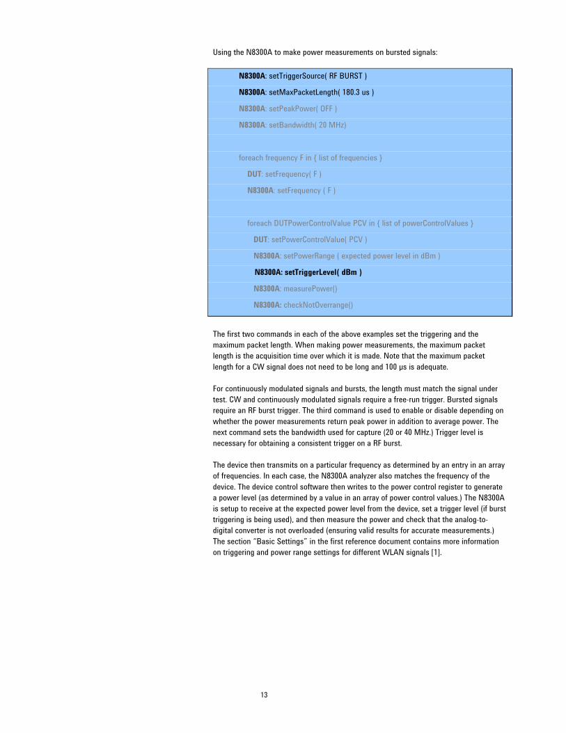
Using the N8300A to make power measurements on bursted signals:
N8300A: setTriggerSource( RF BURST )
N8300A: setMaxPacketLength( 180.3 us )
N8300A: setPeakPower( OFF )
N8300A: setBandwidth( 20 MHz)
foreach frequency F in { list of frequencies }
DUT: setFrequency( F )
N8300A: setFrequency ( F )
foreach DUTPowerControlValue PCV in { list of powerControlValues }
DUT: setPowerControlValue( PCV )
N8300A: setPowerRange ( expected power level in dBm )
N8300A: setTriggerLevel( dBm )
N8300A: measurePower()
N8300A: checkNotOverrange()
The first two commands in each of the above examples set the triggering and the maximum packet length. When making power measurements, the maximum packet length is the acquisition time over which it is made. Note that the maximum packet length for a CW signal does not need to be long and 100 µs is adequate. For continuously modulated signals and bursts, the length must match the signal under test. CW and continuously modulated signals require a free-run trigger. Bursted signals require an RF burst trigger. The third command is used to enable or disable depending on whether the power measurements return peak power in addition to average power. The next command sets the bandwidth used for capture (20 or 40 MHz.) Trigger level is necessary for obtaining a consistent trigger on a RF burst. The device then transmits on a particular frequency as determined by an entry in an array of frequencies. In each case, the N8300A analyzer also matches the frequency of the device. The device control software then writes to the power control register to generate a power level (as determined by a value in an array of power control values.) The N8300A is setup to receive at the expected power level from the device, set a trigger level (if burst triggering is being used), and then measure the power and check that the analog-to-digital converter is not overloaded (ensuring valid results for accurate measurements.) The section “Basic Settings” in the first reference document contains more information on triggering and power range settings for different WLAN signals [1].

14
Phase 2 – Received Signal Strength Indicator (“RX Cal”)
The received signal strength indicator (RSSI) value indicates the strength of a received signal as measured by the DUT. The DUT needs to be supplied with a set of signals of varying power levels and frequencies from which a table in the EEPROM can be populated with information. This allows the DUT to convert from a unitless internal signal strength value to a calibrated result in dBm.
Test procedure The following example assumes that the same offset frequency (offset from center frequency) and power levels are being tested in each band for simplicity. The source and device are set to the first channel in the band. The N8300A source is then switched on to output a CW tone at the starting power level, assuming no frequency offset i.e. the first frequency for test (see playCW( SP, 0 ).) Two nested loops then read the RSSI, adjusting the N8300A output power at each power level until complete. Once the power levels have been looped through, the device is set to a new frequency. Similarly, the N8300A is set to a new frequency using the offset frequency. Looping continues until all channels are tested. Each band is tested in the same way. Before switching bands, the source must be switched off and then on again in the new band as the adjustment of the source is only valid within a band. The following procedures allow the N8300A to be used for CW receiver calibration:
SP = startPower
foreach band B in { 2.4 GHz, 5 GHz }
DUT: setFrequency( B )
N8300A: setFrequency( B )
N8300A: playCW( SP, 0 )
foreach offsetfrequency OF = { list of frequencies }
DUT: setFreq( B+OF )
foreach sourcePowerLevel PL in { list of powerLevels }
N8300A: adjustOutput( PL, 0F )
wait()
DUT: readRSSIvalue()
N8300A: stopTX()
15
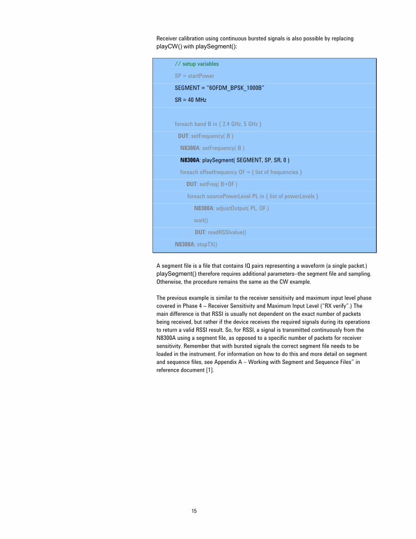
Receiver calibration using continuous bursted signals is also possible by replacing playCW() with playSegment():
// setup variables
SP = startPower
SEGMENT = “6OFDM_BPSK_1000B”
SR = 40 MHz
foreach band B in { 2.4 GHz, 5 GHz }
DUT: setFrequency( B )
N8300A: setFrequency( B )
N8300A: playSegment( SEGMENT, SP, SR, 0 )
foreach offsetfrequency OF = { list of frequencies }
DUT: setFreq( B+OF )
foreach sourcePowerLevel PL in { list of powerLevels }
N8300A: adjustOutput( PL, OF )
wait()
DUT: readRSSIvalue()
N8300A: stopTX()
A segment file is a file that contains IQ pairs representing a waveform (a single packet.) playSegment() therefore requires additional parameters–the segment file and sampling. Otherwise, the procedure remains the same as the CW example. The previous example is similar to the receiver sensitivity and maximum input level phase covered in Phase 4 – Receiver Sensitivity and Maximum Input Level (“RX verify”.) The main difference is that RSSI is usually not dependent on the exact number of packets being received, but rather if the device receives the required signals during its operations to return a valid RSSI result. So, for RSSI, a signal is transmitted continuously from the N8300A using a segment file, as opposed to a specific number of packets for receiver sensitivity. Remember that with bursted signals the correct segment file needs to be loaded in the instrument. For information on how to do this and more detail on segment and sequence files, see Appendix A – Working with Segment and Sequence Files” in reference document [1].

16
For an 802.11n device, RSSI is required for each channel. Additionally, a composite RSSI value may be obtained alongside individual channel RSSI for further calibration checks. This requires the N8300A to transmit from any configuration of multiple ports at one time, referred to as broadcast mode. The following example demonstrates the use of continuous bursted signals for receiver calibration with broadcast mode:
// setup variables
SP = startPower
SEGMENT = “6OFDM_BPSK_1000B”
SR = 40 MHz
// setup broadcast mode
N8300A: setPorts( RFIO1 & RFIO2 & RFIO3 )
N8300A: setBroadcastMode( ON )
foreach band B in { 2.4 GHz, 5 GHz }
DUT: setFrequency( B )
N8300A: setFrequency( B )
N8300A: playSegment( SEGMENT, SP, SR, 0 )
foreach offsetfrequency OF = { list of frequencies }
DUT: setFreq( B+OF ) foreach sourcePowerLevel PL in { list of powerLevels }
N8300A: adjustOutput( PL, 0F )
wait()
DUT: readRSSIvalues()
N8300A: stopTX()
The code above illustrates that the only difference with using the N8300A is that broadcast mode must be switched on and the port configuration set at the start. Unless changed, all subsequent tests will use the specified configuration. For the device, it is assumed that with broadcast mode multiple RSSI values are returned (i.e. an RSSI value is returned for each of the three chains.) A composite RSSI may also be returned.

17
Phase 3 – Spectral Mask and Power Verification (“TX Verify”)
Phase 3 contains two types of measurements in the N8300A: power (as with Phase 1) and spectral mask.
Power verification The power verification is meant to verify the success of the TX CAL in Phase 1. Within Phase 1 the device is calibrated across a number of points in the operational range. The power verification may check the power output over a number of different frequencies but also at different power levels, potentially interpolating between the power levels calibrated previously.
Spectral mask A spectral analysis of the signal is required to ensure that the device outputs a signal that fits IEEE standards and regulatory requirements. The test is normally done at the maximum output power of the device over a number of channels.
Test procedure Power verification The test below loops using the frequency and device power level for power verification. The trigger level changes as the device is transmitting at different calibrated levels (requested in dBm) to the N8300A to validate the transmission range.
// basic setup & power triggering
N8300A: setTriggerSource( RF BURST )
N8300A: setMaxPacketLength( 967 us )
N8300A: setTriggerDelay( -2 us )
N8300A: setTriggerDelayState( ON )
N8300A: setTriggerHoldoff( 1 us )
N8300A: setTriggerHoldoffState( ON )
// power measurement setup
N8300A: setPeakPower( OFF )
N8300A: setBandwidth( 20 MHz )
foreach frequency F in { list of frequencies }
DUT: setFrequency( F )
N8300A: setFrequency ( F )
foreach DUTPowerLevel DPL in { list of dBmPowerLevels }
DUT: setPowerLevel( DPL )
N8300A: setPowerRange ( PR )
N8300A: setTriggerLevel ( dBm )
N8300A: measPower()
N8300A: checkNotOverrange()

18
Spectral mask When the highest power is reached, a spectral mask test is performed. Normally the highest power output is chosen since the amplifier will be stressed appropriately and may exhibit undesired spectral components. This implies that the spectral mask test is being looped by frequency only (and not tested for each power level). This is illustrated below for an IEEE 802.11b, 11-Mbps signal:
// basic setup & spectral mask triggering
N8300A: setTriggerSource( RF BURST )
N8300A: setMaxPacketLength( 967 us )
N8300A: setTriggerDelay( -2 us )
N8300A: setTriggerDelayState( ON )
N8300A: setTriggerHoldoff( 1 us )
N8300A: setTriggerHoldoffState( ON )
// power measurement setup
N8300A: setPeakPower( OFF )
N8300A: setBandwidth( 20 MHz )
// spectral mask setup
N8300A: setWLANFormat( B )
N8300A: setMASkAveraging( OFF )
N8300A: setFastMask( ON )
N8300A: setRelativeMask( AUTO )
N8300A: setSpan( 66 )
N8300A: setWindowing( GAUSSIAN )
foreach frequency F in { list of frequencies }
DUT: setFrequency( F )
N8300A: setFrequency ( F )
foreach DUTPowerLevel DPL in { list of dBmPowerLevels }
DUT: setPowerLevel( DPL )
N8300A: setPowerRange ( PR )
N8300A: setTriggerLevel ( dBm )
N8300A: measPower()
N8300A: checkNotOverrange()
if (DPL == MaxPower)
N8300A: measSpectralMask()
N8300A: checkNotOverrange()

19
Phase 4 – Receiver Sensitivity and Maximum Input Level (“RX Verify”)
By this phase of the test plan, it has been proven that the transmitter can generate signals. It is now time to find out whether the receiver can receive bursted signals and to verify the receiver calibration. Bursted signals may have been used in calibration, but the number of packets successfully received will not have been checked. Receiver sensitivity checks that the receiver (or receivers in the case of IEEE 802.11n) can successfully receive packets, without error, that are sent to it at a known power level and frequency from the N8300A. This maybe done in two parts: 1. At a very low power level, to ensure that the device sensitivity is correct 2. At the highest power level the device should to be able to receive successfully,
(sometimes known as saturation.) Saturation is not always carried out in manufacturing test plans but normally some check is made at a higher power (and not just at low power levels)
These two conditions are determined by the relevant IEEE specification. For receiver sensitivity testing a variety of modulation formats is used to test the accuracy of the receiver. Typically, a sequence file will be used which results in the repetition of a transmission of a packet, or segment, for example, one thousand times (which is normal for WLAN specifications.) A sequence file is a sequence of segment files allowing for playback of one or more segment files a set number of times. To make receiver testing more straightforward, segment and sequence files are included with the N8300A. These files are suitable for the vast majority of devices for production testing. For more details see Appendix A in reference document [2].

20
Test procedure // setup variables
P1 = lowestPower
P2 = highestPower
SEQUENCE = “54OFDM_64QAM_1000B.SEQ”
SR = 40 MHz
foreach frequency F in { list of frequencies }
N8300A: setFrequency( F )
N8300A: setSequence( SEQUENCE, P1, SR, 0 ) // set lowest power level
DUT: setupDUTRx() // prepare DUT for receive packets RX
N8300A: triggerSequence()
while (NOT sequenceComplete() )
wait();
DUT: readPacketCount() // read packets RX
if (readPacketCount() < threshold) // if not acceptable
fail() // record fail
N8300A: setSequence( SEQUENCE, P2, SR, 0) // set highest power level
N8300A: triggerSequence()
while (NOT sequenceComplete() )
wait();
DUT: readPacketCount()
if (readPacketCount() < threshold)
fail()
The previous procedure demonstrates receiver sensitivity testing at two different power levels. The N8300A is armed for playback by selecting a sequence file allowing the sequence to be subsequently triggered. The N8300A is then asked when it has finished transmitting all the packets. There are other ways to determine when the device needs to be polled for a result, but they tend to be less reliable. A timing loop could be used or the device could count up to a value. However, these approaches are likely to encounter problems. For example, timing would have to be modified if source waveforms were changed. Also, a device counting towards a value is not a good idea if the device does not receive the correct number of packets expected, which can result in a timeout. The latter two approaches are more successful if the N8300A is simply asked to transmit continuously and not for a set number of packets. Given the ability of the test set to playback a fixed number of packets using sequence files and determine when that operation is complete, this is the optimum method for any reliable receiver test.

21
Phase 5 – Modulation Accuracy (“TX Quality”)
Before embarking on this phase of the test plan, the values determined in the previously completed calibration phases should have been written to the EEPROM in the DUT. By now, a lot is known about the device: 1. It can be instructed to generate signals at a power level in dBm that is requested,
i.e. calibrated and verified 2. It can report the power level of a received signal in dBm 3. It can receive packets successfully at two different power levels
The last task is to ensure that when the DUT generates a signal at a known (calibrated) power level that it is generated cleanly enough that a receiving device is able to decode the signal. It is known that the device should be able to generate signals of a given level, so stable triggering should be easily achieved for a passing device. The primary measurement of modulation accuracy is EVM. It is normal to set the DUT to transmit at a high power level to check the performance of the amplifier. This works especially well given that high-power transmissions tend to work at the maximum levels intended by the chipset designer before any undesired problems might be observed. Checking the EVM result ensures that the amplifier is not saturated and that is within a working level specification.

22
Test procedure The test procedure below loops by frequency and power level, changing the transmitted signal power depending upon a list (array) of power levels for each frequency. Typically, this is just one test power level at maximum output. The procedures below are for an IEEE 802.11a, 54-Mbps OFDM signal:
// basic setup
N8300A: setWLANFormat( A )
N8300A: SetMaximumSymbols( 43 )
N8300A: setTriggerSource( RF BURST )
N8300A: setMaxPacketLength( 185.2 us )
N8300A: setTriggerDelay( -5 us )
N8300A: setTriggerDelayState( ON )
N8300A: setTriggerHoldoff( 1 us )
N8300A: setTriggerHoldoffState( ON )
// demod measurement setup
N8300A: setEVMAveraging( OFF )
N8300A: setEqualizer( ENHANCED )
N8300A: setEstimation( OFF )
N8300A: setGatedPower( ON )
N8300A: setLeftGate( -15 us )
N8300A: setRightGate( 0 us )
N8300A: setOffset( 0 )
N8300A: setTrackAmp( OFF )
N8300A: setTrackPhase( ON )
N8300A: setTrackTiming( OFF )
foreach frequency F in { list of frequencies }
DUT: setFrequency( F )
N8300A: setFrequency( F )
foreach DUTPowerLevel DPL in { list of dBmPowerLevels }
DUT: setPowerLevel( DPL )
N8300A: setPowerRange( dBm )
N8300A: setTriggerLevel( TL )
N8300A: measDemod()
N8300A: checkNotOverrange()
23
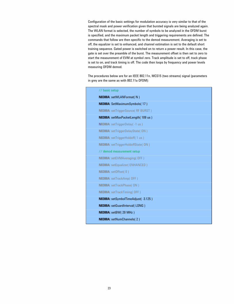
Configuration of the basic settings for modulation accuracy is very similar to that of the spectral mask and power verification given that bursted signals are being analyzed again. The WLAN format is selected, the number of symbols to be analyzed in the OFDM burst is specified, and the maximum packet length and triggering requirements are defined. The commands that follow are then specific to the demod measurement. Averaging is set to off, the equalizer is set to enhanced, and channel estimation is set to the default short training sequence. Gated power is switched on to return a power result. In this case, the gate is set over the preamble of the burst. The measurement offset is then set to zero to start the measurement of EVM at symbol zero. Track amplitude is set to off, track phase is set to on, and track timing is off. The code then loops by frequency and power levels measuring OFDM demod. The procedures below are for an IEEE 802.11n, MCS15 (two streams) signal (parameters in grey are the same as with 802.11a OFDM):
// basic setup
N8300A: setWLANFormat( N )
N8300A: SetMaximumSymbols( 17 )
N8300A: setTriggerSource( RF BURST )
N8300A: setMaxPacketLength( 109 us )
N8300A: setTriggerDelay( -1 us )
N8300A: setTriggerDelayState( ON )
N8300A: setTriggerHoldoff( 1 us )
N8300A: setTriggerHoldoffState( ON )
// demod measurement setup
N8300A: setEVMAveraging( OFF )
N8300A: setEqualizer( ENHANCED )
N8300A: setOffset( 0 )
N8300A: setTrackAmp( OFF )
N8300A: setTrackPhase( ON )
N8300A: setTrackTiming( OFF )
N8300A: setSymbolTimeAdjust( -3.125 )
N8300A: setGuardInterval( LONG )
N8300A: setBW( 20 MHz )
N8300A: setNumChannels( 2 )

24
foreach frequency F in { list of frequencies }
DUT: setFrequency( F )
N8300A: setFrequency( F )
foreach DUTPowerLevel DPL in { list of dBmPowerLevels }
DUT: setPowerLevel( DPL )
N8300A: setPowerRange( dBm )
N8300A: setTriggerLevel( TL )
N8300A: measDemod()
N8300A: fetchBurstInfo()
N8300A: checkNotOverrange()
802.11n measurements require some additional setup. For example, the number of DUT channels being analyzed must be set, hence the number of RF ports required for use in demodulation on the N8300A must be setup. The 802.11n demodulation returns a wide range of results. The more channels that are set, the more individual channel parameters can be analyzed. The fetchBurstInfo() command is also included to return information on the burst that was analyzed. This provides comprehensive validation of the individual fields within the 802.11n burst, complementing the key RF measurements returned by the measDemod(). The procedures below are for an IEEE 802.11b, 11-Mbps DSSS signal (grey indicates pseudo code similar to the OFDM example):
// basic setup
N8300A: setWLANFormat( B )
N8300A: setTriggerSource( RF BURST )
N8300A: setMaxPacketLength( 967 us )
N8300A: setTriggerDelay( -2 us )
N8300A: setTriggerDelayState( ON )
N8300A: setTriggerHoldoff( 1 us )
N8300A: setTriggerHoldoffState( ON )
// demod measurement setup
N8300A: setEVMAveraging( OFF )
N8300A: setEqualizer( ENHANCED )
N8300A: setGatedPower( ON )
N8300A: setLeftGate( 0 us )
N8300A: setRightGate( 100 us )
N8300A: setOffset( 22 )
N8300A: setTrackPhase( OFF )

25
foreach frequency F in { list of frequencies }
DUT: setFrequency( F )
N8300A: setFrequency( F )
foreach DUTPowerLevel DPL in { list of dBmPowerLevels }
DUT: setPowerLevel( DPL )
N8300A: setPowerRange( dBm )
N8300A: setTriggerLevel( TL )
N8300A: measDemod()
N8300A: checkNotOverrange()
EVM results and troubleshooting Regardless of the particular format, it should be noted that there are a number of advanced settings that may be configured for EVM measurements. When comparing EVM measurements with other test equipment, result sets, and when addressing IEEE specifications, consider the following: 1. Are the equalizer training settings similar and do they need to conform to IEEE
specifications? For example, some test vendors will default to using non-compliant equalizers that can sometimes produce lower EVM. An enhanced equalizer is switched on in the previous examples. This equalizer is trained by analyzing the entire OFDM burst. This includes the channel estimation sequence within the preamble and the data symbols. This training usually provides a more accurate estimate of the true response of the transmission channel. As a result, this typically means a lower EVM than normal equalization because the equalizer is less impacted by noise and distortion.
2. Is the symbol timing adjust setting consistent and appropriate? 3. Is the subcarrier spacing correct? 4. Was the analyzer set to track amplitude changes in the pilot subcarriers? 5. Was the analyzer set to track phase changes in the pilot subcarriers? 6. Was the analyzer set to track timing changes in the pilot subcarriers? 7. Consider carefully all the basic settings (presented in “Basic Settings” in reference
document [1] on RF accuracy, repeatability, and test time) that influence demod measurements. For example, maximum packet length is key to determining how long the measurement takes and how much of the burst is analyzed. The maximum number of symbols should also be checked for OFDM frames in relation to how many symbols are being analyzed for EVM results.
8. Averaging is sometimes enabled in order to average over a number of bursts to reduce the effects of high EVM in the occasional bad burst. This may reduce the EVM value returned. However, it might also be hiding a problem with the device and increasing test time unnecessarily.

26
Specifically for 802.11n results: 9. A device operating in direct map mode is highly desirable in order to achieve the
best analysis of its RF characteristics. If results do not look correct, then it is recommended that the mode of the device be checked. For example, in the particular case of a DUT operating in spatially-mapped mode (spatial expansion), any channel isolation or leakage effects will be masked by the deliberate mapping of spatial streams across transmitter channels. In this situation, the cross power values will provide a measure of the degree of spatial expansion used, dependant on the Q-matrix.
10. Remember that N8300A results are returned for each individual channel of the device. It is therefore important to check that all RF chains are passing limits and specifications in order to determine a device pass condition.
11. The EVM per channel allows for fast troubleshooting of individual RF chains of a device. However, a poor EVM result on its own does not provide the root cause. Use the vast range of other results available from the N8300A to troubleshoot failures. One of the most common results in diagnosing a failure per channel is cross channel power. This provides an indication of the isolation between RF chains on a device. Adequate isolation between chains is a key requirement for a MIMO device to realize its potential when compared with single-channel legacy devices. Consequently, if a device exhibits poor EVM it may point towards poor isolation between chains, i.e. the unintentional leakage of streams into other channels when a device operates in a direct map mode. It should be noted that if isolation is extremely poor, the measurement algorithm used to demodulate will not be able to produce a good EVM result.
12. Do not confuse the individual channel EVM results from the N8300A with proprietary EVM results from other test vendors, such as composite EVM. For example, composite EVM has no relation to IEEE specifications and is produced as a result of using a combiner to combine channels from a device. Combining channels means that there is no isolation between chains within the test setup. Such a test setup adversely affects the ability of an OBT to make measurements applicable to a multi-channel device.
27
References
[1] IEEE 802.11a/b/g/n Manufacturing Test with the N8300A, Part 2: Implementation of a WLAN test plan using SCPI programming, application note, literature number 5989-9959EN. [2] IEEE 802.11a/b/g/n Manufacturing Test with the N8300A, Part 3: Techniques for optimizing WLAN device testing, application note, literature number 5989-9960EN. [3] IEEE 802.11a/b/g/n Manufacturing Test with the N8300A, Part 4: How to migrate from the N4010 to N8300A for WLAN testing, application note, literature number 5989-9961EN. [4] IEEE 802.11n PHY Service Specification. [5] Agilent MIMO Manufacturing Solution, application note, literature number 5989-7037EN. [6] N4010A WLAN IEEE 802.11a/b/g/n Video Series, section “N4010A/N4011A 802.11n Test”, http://www.agilent.com/find/n4010A_videos.

28
Glossary
API Application programmable interface ACP Adjacent channel power, sometimes referred to as adjacent channel
leakage ratio (ACLR), is a measure of the transmitter energy that is “leaking” into an adjacent or alternate channel
CW Continuous wave Direct map mode
A term used in IEEE 802.11n device testing. For a simple case of direct map mode, each spatial stream is mapped directly to its corresponding transmitter channel. There is a one-to-one mapping of stream to chain. This is in contrast to a device using spatial expansion
DSSS Direct-sequencing spread spectrum DUT Device under test (the device being tested) EVM Error vector magnitude EEPROM Electrically erasable programmable read-only memory IEEE Institute of Electrical and Electronic Engineers ISM Industrial, scientific and medical IQ In phase/Quadrature (also presented as “I/Q”) MCS Modulation and coding scheme MIMO Multiple-in and multiple-out OBT One box tester OFDM Orthogonal frequency-division multiplexing PER Packet error rate RSSI Received signal strength indicator Segment file A file containing a representation of a waveform, which can be played
by the N8300A source Sequence file A file containing one or more pairs of (segment file name, count) which
is used to cause the segment file to be played a specific number of times
SCPI Standard commands for programmable instruments Spatial expansion
A term used in IEEE 802.11n device testing to indicate that constellation points from each stream are multiplied by a matrix and then transmitted through different transmit chains. This means that more than one stream exists on a channel, in contrast to a device using direct map mode
WiMAX Worldwide interoperability for microwave access WLAN Wireless local area network

29
Appendix A: Loss Compensation Calculations
CW signals may be generated from the N8300A to be used for loss compensation calculations. The SCPI below provides a CW tone at the requested power (–20 dBm) and frequency (2.412 GHz):
:INSTrument:SELect WLAN
:SENSe:FREQuency:CENTer 2.412 GHz
:SOURce:CWTone –20,0
The SCPI can be replicated on the front panel of the N8300A by pressing the [Source] button while in WiMAX mode, selecting any waveform, selecting a power level, choosing a frequency, turning the RF output on, and leaving the arbitrary waveform generator off.
Similarly, the N8300A can measure the CW returned from fixtures for loss calculations. In some cases the power level expected by the N8300A from the test fixturing is unknown. If this is the case, it is advised that a high power range be used. Then, make an average power measurement with free run triggering. The power measurement may be inaccurate due to the high power range setting in the instrument. However, the power reading can then be used to set the power range value. Using a slightly higher level just above the first reading, such as 2 dBm, is recommended. Another power reading with the new power range provides an accurate power level that can then be used in loss compensation calculations. The steps explained offer a way of doing a CW Autorange.

30
Appendix B: DUT Command List
For reference, the following pseudo commands were used throughput the test phases as a means of describing what a device must do to be tested at each stage: DUT pseudo command reference/operation Description
setFrequency( F ) Sets the frequency (F) of the device
setTX( CW ) Sets the device to transmit a CW tone as part of calibration routines
readSynchCondition( ) Determines whether the device has successfully synchronized to the downlink signal from the N8300A
setPowerControlValue( PCV )
Sets a transmit output level in the device according to an array of power control values which can subsequently be calibrated by the instrument. (PCV is manufacturer-specific, uncalibrated, unitless)
setupDUTRx() Prepares the DUT to receive packets
readRSSIvalue( ) Queries the received signal strength indication from the device
readRSSIvalues( )
Queries the received signal strength indication from each channel of a device and/or returns composite RSSI values. This is required for an 802.11n device with multiple channels
readPacketCount( ) Queries successful packets received
setPowerLevel( DPL )
Sets a transmit output power level following a request for a particular dBm power level, where DPL is a dBm value that is part of an array. This command is only valid once transmit calibration has been completed. (See setPowerControlValue( PCV ) above)

31

32
“WiMAX” is a trademark of the WiMAX Forum.
www.agilent.com For more information on Agilent Technologies’ products, applications or services, please contact your local Agilent office. The complete list is available at: www.agilent.com/find/contactus Americas Canada Latin America United States
(877) 894-4414 305 269 7500 (800) 829-4444
Asia Pacific Australia China Hong Kong India Japan Korea Malaysia Singapore Taiwan Thailand
1 800 629 485 800 810 0189 800 938 693 1 800 112 929 0120 (421) 345 080 769 0800 1 800 888 848 1 800 375 8100 0800 047 866 1 800 226 008
Europe & Middle East Austria Belgium Denmark Finland France
Germany
01 36027 71571 32 (0) 2 404 93 40 45 70 13 15 15 358 (0) 10 855 2100 0825 010 700* *0.125 €/minute
07031 464 6333
Ireland Israel Italy Netherlands Spain Sweden Switzerland United Kingdom
1890 924 204 972-3-9288-504/544 39 02 92 60 8484 31 (0) 20 547 2111 34 (91) 631 3300 0200-88 22 55 0800 80 53 53 44 (0) 118 9276201
Other European Countries: www.agilent.com/find/contactus Revised: October 1, 2008
Product specification and descriptions in this document subject to change without notice. © Agilent Technologies, Inc. 2009 Printed in USA, April 21, 2009 5989-9958EN