IEC 61850 Modelling Guideline Power Conversion and FACTS · 0 IEC 61850 Modelling Guideline Power...
82
0 IEC 61850 Modelling Guideline Power Conversion and FACTS Working Group „Umrichtermodellierung mit IEC 61850“ 5/31/2016
Transcript of IEC 61850 Modelling Guideline Power Conversion and FACTS · 0 IEC 61850 Modelling Guideline Power...

0
IEC 61850 Modelling Guideline
Power Conversion and FACTS Working Group „Umrichtermodellierung mit IEC 61850“
5/31/2016

1
Contents
Contents .................................................................................................................. 1
1 Foreword ........................................................................................................... 4
2 Introduction ........................................................................................................ 5
2.1 General ..................................................................................................... 5
2.2 Applications ............................................................................................... 5
2.3 Benefits ..................................................................................................... 5
2.3.1 Design phase .................................................................................. 6
2.3.2 Implementation phase ..................................................................... 6
2.3.3 Operation and maintenance phase ................................................... 6
3 Scope ................................................................................................................ 7
3.1 General ..................................................................................................... 7
3.2 Abbreviated terms ...................................................................................... 8
3.3 Abbreviated terms used in data object names ............................................. 9
4 Modelling approach for Power Converter and FACTS Systems .......................... 10
4.1 General ................................................................................................... 10
4.2 Description of the power conversion and FACTS parts .............................. 10
4.2.1 Point of connection grid 1 (=X1) ..................................................... 10
4.2.2 Transformer 1 (=TA1) .................................................................... 11
4.2.3 Grid 1 Filter (=RF1) ....................................................................... 11
4.2.4 Grid 1 converter (=TB1) ................................................................. 11
4.2.5 DC circuit (=C1) ............................................................................ 11
4.2.6 Grid 2 converter (=TB2) ................................................................. 11
4.2.7 Converter Cooling System (=GQ) ................................................... 11
4.2.8 Auxiliary Power System (=GZ) ....................................................... 11
4.2.9 Transformer 2 (=TA2) .................................................................... 11
4.2.10 Grid 2 Filter (=RF2) ....................................................................... 11
4.2.11 Point of connection Grid 2 (=X2) .................................................... 11
4.3 Description of different applications .......................................................... 12
4.3.1 Power Conversion ......................................................................... 12
4.3.2 FACTS .......................................................................................... 14
4.4 Generic Control Application ...................................................................... 16
5 Use Cases ....................................................................................................... 18
5.1 Change of operation status ...................................................................... 18
5.2 Sequence Abort ....................................................................................... 19
5.3 Quick Shutdown ....................................................................................... 19
5.4 Operation mode ....................................................................................... 20
5.5 Change of characteristic curve ................................................................. 21
5.6 Activate external reference ....................................................................... 22
6 Description of basic modelling approach for IEC 61850 ..................................... 24
6.1 General ................................................................................................... 24
6.2 Enumerations .......................................................................................... 24
6.3 Modelling conventions .............................................................................. 24
6.3.1 Measurement ................................................................................ 24
2
6.3.2 Supervision ................................................................................... 24
6.3.3 Protection ..................................................................................... 24
6.3.4 Control and alarm handling ............................................................ 24
6.3.5 Description of characteristic curve for converter/FACTS control ...... 25
6.3.6 Logical Nodes classes ................................................................... 26
7 Description of new LNs, DOs, Enumerations ..................................................... 27
7.1 Enumerations .......................................................................................... 28
7.1.1 General ......................................................................................... 28
7.1.2 Charge DC status (ChaDCStKind enumeration) .............................. 29
7.1.3 Configuration DC status (ConfDCStKind enumeration) ................... 29
7.1.4 Connection DC status (ConnDCStKind enumeration) ...................... 29
7.1.5 Generation DC status (GenDCStKind enumeration) ........................ 30
7.1.6 Mode P (ModPKind enumeration) .................................................. 30
7.1.7 Mode Q (ModQKind enumeration) .................................................. 30
7.1.8 Operation command (OperationCmdKind enumeration) .................. 31
7.1.9 Operation Status (OperationStKind enumeration) ........................... 31
7.1.10 Sequencer status (SeqStKind enumeration) ................................... 31
7.2 New or extended classes ......................................................................... 32
7.2.1 General ......................................................................................... 32
7.2.2 Package LNGroupA ....................................................................... 33
7.2.3 Package LNGroupC ....................................................................... 36
7.2.4 Package LNGroupK ....................................................................... 41
7.2.5 Package LNGroupM ...................................................................... 46
7.2.6 Package LNGroupX ....................................................................... 49
7.3 Used, existing classes ............................................................................. 53
7.3.1 LNGroupK ..................................................................................... 53
7.3.2 LNGroupM .................................................................................... 53
7.3.3 LNGroupP ..................................................................................... 54
7.3.4 LNGroupS ..................................................................................... 54
7.3.5 LNGroupY ..................................................................................... 54
7.3.6 LNGroupZ ..................................................................................... 55
7.4 Data semantics ........................................................................................ 55
8 Description of specific Applications ................................................................... 58
8.1 SVC ........................................................................................................ 58
8.2 SFC ......................................................................................................... 61
8.3 HVDC ...................................................................................................... 62
Annex A SCL enumerations ................................................................................... 65
Annex B SCL-Description of different applications .................................................. 67
Annex C State Machines ........................................................................................ 68
Annex D Description of Characteristic Curves ......................................................... 71
D.1 Application SFC ....................................................................................... 72
D.1.1 Operation Mode: P-f characteristic ................................................. 72
D.1.2 Operation Mode: P fixed ................................................................ 73
D.1.3 Operation Mode: P-V characteristic ................................................ 73
D.1.4 Operation Mode: Q-V characteristic ............................................... 74

3
D.1.5 Operation Mode: Q fixed ................................................................ 75
D.1.6 Operation Mode: Phi fixed ............................................................. 76
D.2 Application SVC ....................................................................................... 77
D.2.1 Operation Mode: Q-V characteristic ............................................... 77
D.2.2 Operation Mode: Q fixed ................................................................ 77
D.3 Application HVDC .................................................................................... 79
D.3.1 Operation Mode: P-F characteristic ................................................ 79
D.3.2 Operation Mode: P fixed ................................................................ 79
D.3.3 Operation Mode: P-V characteristic ................................................ 79
D.3.4 Operation Mode: Q-V characteristic ............................................... 79
D.3.5 Operation Mode: Q fixed ................................................................ 80
D.3.6 Operation Mode: Phi fixed ............................................................. 80
Annex E Borders/Remarks ..................................................................................... 81

4
1 Foreword
This document was prepared by a working group of the Committee 952.0.10 of the German Commission for Electrical, Electronic & Information Technologies (DKE AK 952.0.10). The aim of this working group was the development of an IEC 61850 modelling for FACTS and power conversion systems. In detail existing applications like HVDC, SFC and FACTS were analysed and the requirements for a communication based on IEC 61850 described. Where needed new LNs were defined to have a complete IEC 61850 data model for these applications.
Working group members:
Jan Arph, H & S Hard- & Software Technologie GmbH & Co. KG
Thomas Bauer, Bayernwerk AG
Thomas Falkenhagen, DB Energie GmbH
Hans-Jürgen Gruber, TenneT TSO GmbH
Armin Heinrich, TenneT TSO GmbH
Kay Herbst, DB Energie GmbH
Josef Hochleitner, Siemens AG
Carsten Kelbert, Siemens AG
Dr. Jürgen Kurrat, ABB AG
Stephan Mertens, Balfour Beatty Rail GmbH
Hans-Günther Platz, Siemens AG
Thomas Röseler, Maschinenfabrik Reinhausen GmbH
Alexander Schlachter, ABB AG
Nicolas Söllner, Siemens AG
Jens Specht, Siemens AG
Jan-Thomas Walther, DB Energie GmbH

5
2 Introduction
2.1 General
Static Frequency Converters (SFC) and rectifiers for rail grid applications and public power grids, Static Var Compensators (SVC), Static Synchronous Compensators (STATCOM) and High-Voltage DC transmission (HVDC)-systems usually are remote controlled by Network Control Center (NCC). Therefore these systems are integrated in the substation automation system. Up to now different communication protocols are used for this link (e.g. IEC 60870-5-101, -104, Modbus, Profibus). The aim of this work is to map the existing implementations of control for power converter und Flexible AC Transmission Systems (FACTS) to a common consistent communication solution based on standard IEC 61850.
Exemplary following operation issues have to be considered:
Toggle between different operation status (e.g. on, off, standby) by local or remote SCADA-system.
Selection of operation modes (e.g. self-sustaining automatic control, Variable frequency characteristic) by local or remote SCADA-system
Change of reference values and parameters by local or remote SCADA-system
Transmission of data points for visualisation of characteristics to SCADA-System
Transmission of status informations and alarms to SCADA-system
Monitoring issues
2.2 Applications
SFCs and rectifiers for rail grid applications and public power grids, SVC, STATCOM and HVDC-systems are used for active controlling the electric power. These applications can be divided into
Power conversion: Active and reactive power is controlled. Example applications are
o SFC
o Rectifiers
o Inverters
o HVDC transmission
FACTS: Only reactive power is controlled. Example applications are
o SVC
o STATCOM
2.3 Benefits
At the different project stages the integration of these applications into the SAS using the IEC 61850 brings versatile benefits.

6
2.3.1 Design phase
Only one tool for the system specification is needed for the design of the communication inside the SAS. This is a basis for an integrated data model including the communication of the SFC, rectifiers, SVC or HVDC.
No separate gateways for protocol conversion are needed.
A multivendor data modelling is achievable.
A database with typical applications in a SAS including SFC, rectifiers, SVC and HVDC can be used.
2.3.2 Implementation phase
A reduction of the implementation costs is possible by continuously using the IEC 61850 for the communication between all components inside the substation automation system.
A standardised engineering process can be used.
No protocol conversion inside the SAS is needed.
One data model for all clients in the SAS (local control, proxy to remote control or others)
2.3.3 Operation and maintenance phase
A standardised service process for communication in SAS can be used.
The communication inside the complete SAS can be monitored by one tool.

7
3 Scope
3.1 General
The scope of this document is the description and seamless integration of a generic application model into the SAS using the communication protocol IEC 61850. To support an easy integration into the SAS an open and vendor independent approach is taken. A specific modelling of a generic application model based on IEC 61850 data and communication modelling approach is used.
This document focuses on the applications of SFC and rectifiers for rail grid applications, SVC, STATCOM and HVDC systems. Already existing modelling approaches for systems and components (e.g. transformer, circuit breakers etc.) are not described in this document.
Benefits of the generic modelling approach are:
Reusability of the data model and templates for related use-cases
Manageable number of logical nodes (LN) for complex applications
Improved maintenance of the modelling from standardisation point of view
Less effort for future extensions and changes
Open for future innovations
Support for different standardized applications
Flexible mapping of different customer requirements with the same data model
To guarantee interoperability and to avoid proprietary approaches from different vendors a profiling is needed
Boundary conditions for the generic modelling approach are listed in Annex E.
Existing parts of IEC 61850 have been checked. Part IEC 61850-90-7 focuses on decentralized energy resources (DER). But the operation and control of the applications in this document are different compared to characteristics of DER:
SVC, SFC, rectifiers and HVDC are consumers and producers at the public grid
SVC, SFC, HVDC are controlled by centralized SCADA-Systems in a NCC
Energy demand for the 110-kV-railway network is balanced by primary and secondary grid controller (see 4.3.1.1)
This has consequences on the communication demand and data modelling by IEC 61850. Specifications of operation mode and control options are not available in DER-LN. Using the existing DER-approach a massive extension to the LN would be needed to cover the supplemental data for each of the described applications.
The goal is to define a core data model that covers all considered applications based on a limited number of data objects and a uniform modelling approach.
In this work only the communication based on IEC 61850 that is needed for the operational service, e.g. by a control center, is described. Figure 1 - Scope of this work and document shows this concrete scope and the borders to other interfaces and applications. Further data for maintenance, fault clearance and repair is not in the scope yet because an interoperable specification for operational services is a basic necessity at the first step. Such supplementary information can follow in a second step and these data have normally a specific vendor characteristic.

8
Converter Substation
IED Converter
IED Substation
IEC 61850
Local control
Gateway/Proxy
Remote control
IED Substation
IED Substation
IED Converter
IED Converter
SubstationConverterConverter Substation
OperationOperation
OperationScope
Figure 1 - Scope of this work and document
3.2 Abbreviated terms
Table 1 shows the abbreviations used in this document.
Table 1 - Abbreviations
ABBREVIATION EXPLANATION
AC Alternating Current
DC Direct Current
DER Decentralised Energy Resources
DO Data Object
FACTS Flexible AC Transmission System
HVDC High-Voltage DC Transmission
IGBT Insulated Gate Bipolar Transistor
GC Grid Controller
LCC Line-commutated converter
LN Logical Node
MSC Mechanical Switched Capacitors
MSR Mechanical Switched Reactors
NCC Network Control Center
RCI Remote Control Interface
RLC Resistor-Inductor-Capacitor-Filter
SAS Substation Automation System
SFC Static Frequency Converter
SVC Static Var Compensator
SCADA Supervisory Control and Data Acquisition
STATCOM Static Synchronous Compensator
TCR Thyristor controlled reactor

9
TSC Thyristor switched capacitor
TSR Thyristor switched reactor
UPS Uninterruptable Power Supply
3.3 Abbreviated terms used in data object names
The following terms are used to build concatenated data object names. For example, ChNum is constructed by using two terms "Ch" which stands for "Channel" and "Num" which stands for "Number". Thus the concatenated name represents a "channel number".
Table 2 shows normative terms that are combined to create data object names.
Table 2 - Normative abbreviations for data object names
Term Description
Conf Configuration
Fir Fire

10
4 Modelling approach for Power Converter and FACTS Systems
4.1 General
Chapter 4.3 describes the applications power converters and FACTS.
The objective of this chapter is to introduce a generic power flow controlling system which can be used for different applications. The generic scheme described in this chapter shows the basic structure of a frequency converter model. Parts of the converter in this context and therefore considered in the generic application model are
The converter itself (Primary components and control unit)
Transformers connected directly to the converter
Auxiliary power systems and converter cooling systems
NOTE Considered in the generic application model are
Switchgear branches connected to the converter (described in other parts of IEC 61850)
Grid filter circuits (no relevant information for the operational service)
Specific internal converter solutions which are dependent of the vendor’s realization.
In subchapter 4.2 a generic description of the power converter parts is given. The concrete specification of considered applications follows in subchapter 4.3.
4.2 Description of the power conversion and FACTS parts
The following section describes the generic power conversion and FACTS system basic design. Figure 2 shows the complete generic system with all intended parts.
=X1
=TA1=TB1
=X2
Converter Cooling System
=GQAux.Power
System
=GZ
=TB2=C1
=~ =
~
=TA2
=RF1 =RF2RLC RLC
Figure 2 - Generic converter basic design
4.2.1 Point of connection grid 1 (=X1)
The power conversion and FACTS system is connected to the electric power grid 1 with the point of connection grid 1, =X1.
Grid 1 is defined by:
voltage levels, e.g. 20 kV, 110 kV, 380 kV
frequencies, e.g. 50 Hz, 60 Hz
number of phases, e.g. 1, 2, 3

11
4.2.2 Transformer 1 (=TA1)
Transformer 1 can be of oil-filled or dry type. It can contain several windings with different voltage levels and different numbers of windings. There can be an on-/offload tap changer.
Depending on transformer type, the auxiliary system provides different features, such as
cooling system with e.g. oil pumps, flow supervisions, cooling fans
transformer supervision with e.g. buchholz relay, pressure supervision devices, temperature measurement
4.2.3 Grid 1 Filter (=RF1)
The use of a filter is optional. It can be connected directly to the grid or to a transformer winding.
4.2.4 Grid 1 converter (=TB1)
The technology of the grid 1 converter depends on the aimed application. It controls the power flow or conversion.
4.2.5 DC circuit (=C1)
DC circuit can either be of capacitive or inductive energy storage type, maybe consisting of more than one element. The designation can therefore optionally be defined more precisely.
4.2.6 Grid 2 converter (=TB2)
The technology of the grid 2 converter depends on the aimed application. It controls the power flow or conversion.
4.2.7 Converter Cooling System (=GQ)
Converters and other parts can be air- or liquid-cooled. There are one or more pumps and fans working in parallel or redundant. It supervises i.e. the temperature, the conductivity, the pressure and the flow.
4.2.8 Auxiliary Power System (=GZ)
The auxiliary power system supplies single or redundant electric power with fail-over and an Uninterruptable Power Supply (UPS).
The auxiliary system can offer additional features like infrastructure control and supervision for the building or container.
4.2.9 Transformer 2 (=TA2)
The transformer 2 is described similar to transformer 1. Some converter types can be connected directly to grid 2 without a transformer 2.
4.2.10 Grid 2 Filter (=RF2)
Please see grid 1 filter.
4.2.11 Point of connection Grid 2 (=X2)
The power conversion and FACTS system is connected to the electric power grid 2 with the point of connection grid 2, =X2.
Grid 2 can have
different voltage levels, e.g. 15 kV, 20 kV, 110 kV, 380 kV

12
different frequencies, e.g. 60 Hz, 50 Hz, 16.7 Hz and
a different number of phases, e.g. 1, 2, 3
4.3 Description of different applications
The applications mentioned in the introduction of this document can be described by using the generic converter parts above in other compositions. The applications are divided into power conversion applications and FACTS applications.
4.3.1 Power Conversion
4.3.1.1 Static Frequency Converter
=X1
=TA1 =TB1
=X2
Converter Cooling System
=GQAux.Power
System
=GZ
=TB2=C1
=~ =
~
=TA2
=RF1 =RF2RLC RLC
Figure 3 - Static Frequency Converter Application
Like the rotary phase converter, the static frequency converter (SFC) connects two electric grids (=X1 and =X2), i.e. to interchange electric power. The two grids may have different frequencies and a different amount of phases.
In contrast to the rotary phase converter, the SFC uses power electronics for the power conversion and instead of rotating machines. Static Frequency Converters are sometimes also called frequency changers.
The relation between the electrical values can be nonlinear and is described by operation modes. Annex D.1 shows typical characteristic curves of operation modes. The synchronization with another converter station may be a requested function. This document describes the data model of the converter which can be used to communicate between converter stations. The inter-station synchonization and the communication technique is out of the scope of this document.
The SFC usually consists of two converters, one rectifier and one inverter (=TB1 and =TB2), which are connected by a DC circuit (=C1). Power transformers (=TA1 and =TB2) may adapt the voltage to the level requested by the converter. The SFC system is located in a single converter station and controlled by a superior control function that acts on both converter units. A converter cooling system (=GQ) and an auxiliary power system (=GZ) are required equipment of the converter system. The grid filters (=RF1 and =RF2) reduce the harmonics impressed on the grid by the SFC.
Typical applications for SFC in the high power range are rail converter installations. The railway converters used in different European countries are SFCs or rotary converters and use the electric three phase 50 Hz transport and primary distribution grid to supply power for the two phase 16.7 Hz railway grid or the single phase 15 kV 16.7 Hz railway overhead line.
Another application is shore-to-ship where an anchored ship can shut down the on-board power generation and use the port electricity grid which might have a different frequency.

13
The primary grid controller of the SFC expeditiously sets the operating point following the given characteristic. The secondary grid controller modifies parameters (i.e. FRefC) to fulfil additional needs, e.g. to modify the energy demand and reach contractual targets.
4.3.1.2 HVDC
=~ =
~ Long
Transmission Line
Converter Cooling System
=GQ1
Aux.Power System
=GZ1
Converter Cooling System
=GQ2
Aux.Power System
=GZ2
=X1 =X2
=TA1 =TA2=TB1 =TB2
=RF1 =RF2RLC RLC
Figure 4 - HVDC Application
An HVDC system usually consists of at least two converter stations, realized in thyristor or IGBT valve technology. The converters are connected by means of a common intermediate voltage or current circuit on the DC side. On the AC side they are connected to either the same or independent electrical AC grids (=X1 and =X2) by power transformers (=TA1 and TA2) often equipped with tap changers.
HVDC systems may be installed because of economic considerations, especially for long-distance bulk power transmission - or simply because it is the only feasible solution for the required application, e.g. long subsea cables or network coupling with different nominal frequencies.
The main difference of power transmission with HVDC systems is that, in opposite to conventional meshed AC high voltage grids, active power flow across the link can be actively controlled in any direction, accurately and very fast, reaching control ranges of GW/s. Power transmission is typically performed based on scheduled operator setpoints and superordinated stability functions, which automatically alter or modulate the power flow in case of severe network contingencies like detected power swings, frequency deviations or critical loss of demand or generation.
In addition, also reactive power exchange with the connected networks can be influenced, depending on the technology either continuously by using the converter itself or in discrete steps by switching on and off mechanical switched reactors (MSRs), mechanical switched capacitors (MSCs) or specially tuned harmonic filter circuits (=RF1 and RF2). Thus, an HVDC is also able to inherently fulfil shunt compensation tasks.
As there is a big distance between the stations each individual station has its own auxiliary systems (parts =GZ, =GQ).
HVDC links are usually controlled from one or multiple NCC SCADA-systems, connected to the converter stations via remote control interface (RCI) gateways, and local or remote HMI systems, directly assigned to each station. As converter stations are usually located far away from each other each station has its own independent control system, either acting in a coordinated master/slave principle or communicating to a central higher level grid controller (GC).

14
4.3.1.3 DC-Applications (Rectifiers)
=~
Converter Cooling System
=GQAux.Power
System
=GZ
=X1
=TA1=TB1 =C1
=X2
=RF1RLC
Figure 5 - DC Application (rectifier)
DC railways and most metros have an electric DC traction. Rectifiers (=TB1) source the AC grid (=X1) and supply the traction power with a single phase DC power line (=X2). This power conversion system can be described by leaving the inverter (=TB2), the second transformer (=TA2) and the grid filter =RF2 out of the complete power conversion model. The converter needs a converter cooling system (=GQ) and an auxiliary power system (=GZ). Figure 5 shows a resulting design.
If the rectifier consists of active valves like IGBTs, it can transfer the recoverable energy from the DC power line to the three phase AC grid. For using the recoverable energy with a passive rectifier, please see section 4.3.1.4.
4.3.1.4 DC-Applications (Inverters)
=~ =X1
=TA1=TB1 =C1
=X2
RLC
=~
Converter Cooling System
=GQAux.Power
System
=GZ
=TB2
Figure 6 - DC application (rectifier with inverter)
If the rectifier (=TB1) for railway applications consists of only passive valves then there will have to be an additional inverter to transport the recoverable energy from the DC system (=X2) to the AC grid (=X1). Depending on the network design, the inverter can use same transformer (=TA1) as the rectifier.
Applications for inverters are renewable energy sources (e.g. photovoltaic) for which Figure 5 applies.
4.3.2 FACTS
Flexible AC Transmission Systems (FACTS) comprise various power-electronic based technologies for very fast supply of inductive or capacitive reactive power to the electrical grid under consideration of application specific control strategies. In contrast to Power Conversion systems and in the context of this paper all FACTS considered

15
are parallel (shunt) connected systems. Series connected FACTS are not subject of the present contemplation since their equivalent circuit do not comply with the generic model developed.
The main task of FACTS is not to transport or convert active power, but to control reactive power of grid =X1. Therefore no grid =X2, no transformer =TA2, no filter =RF2 and no converter =TB2 are needed.
4.3.2.1 STATCOM
=~ =X1
=TA1=TB1 =C1
=RF1
Converter Cooling System
=GQAux.Power
System
=GZ
RLC
Figure 7 - STATCOM application
The Static Synchronous Compensator (STATCOM) comprises a system that can be described by the main components coupling transformer (=TA1), the converter circuit (=TB1), the DC link capacitor =C1 and the RLC filter circuit for harmonic current suppression (=RF1). It is connected to a grid =X1. It’s topology and control does allow providing as quick as possible inductive or capacitive power to an electrical grid irrespective of the present value of the grid operation voltage. The converter cooling system (=GQ) and the auxiliary power system (=GZ) accomplish the entire STATCOM system. The relation between the electrical values can be nonlinear and is described by operation modes. Annex D.2 shows typical characteristic curves of operation modes. The power range of technical STATCOM applications vary from some Mvars to systems rated more than 100 Mvar. Typical applications for STATCOM systems in lower power range can be found in the industrial area (e.g. mining, oil & gas) whereas systems representing the high power range can be found in the utility area and in high power consuming industrial environments (e.g. electric arc furnaces).
STATCOM systems and in the context of this paper do have a primary grid controller only which sets the operation point following the given characteristic.
4.3.2.2 SVC
~
Converter Cooling System
=GQAux.Power
System
=GZ
=X1
=TA1
=TB1
Figure 8 - SVC application

16
Like a rotary phase shifting device such as a synchronous generator the Static Var Compensator (SVC) also provides reactive power to an electrical grid. In contrast to the rotary phase shifter, the SVC uses power electronics and passive RLC components instead of rotating machines for providing the reactive power. In the context of this paper the converter (=TB1) consists of a combination of thyristor controlled reactors, thyristor switched capacitors and parallel connected filter circuits. Typically the converter is connected via the transformer (=TA1) to the electrical grid. The converter cooling system (=GQ) and the auxiliary power system (=GZ) accomplish the entire SVC system The relation between the electrical values is linear and is described by operation modes. Annex D.2 shows typical characteristic curves of operation modes. Typical applications for SVC in the high power range (>50 Mvar) are flicker mitigation systems for electric arc furnace applications or voltage and power flow stabilizing systems in power transmission systems.
SVC systems and in the context of this paper do have a primary grid controller only which sets the operation point following the given characteristic.
4.4 Generic Control Application
As shown in chapter 4.3 the different applications are based on the same generic converter application presented in chapter 4.2. From this follows that a generic application model based on IEC 61850 for the generic converter application is useful to describe all the specific applications based on this.
For the operational service of the generic converter application, following aspects are considered:
Measurement
Supervision
Protection
Control
Change of FACTS or power conversion characteristics
Based on these aspects the behaviour of the generic application is controlled by two inputs:
Control of Operation (e.g. off, on, standby)
Control of Output (As output the generic converter provides I, P and Q to the grid.)
Figure 9 shows the application with reference and controlled values in respectively from the same grid. In Figure 10 there is the reference value given from the one grid and the application controls values on another grid.

17
Grid
I, P, Q
(provided to grid)
V, f(determined
by grid)
Control of Operation - application
specific control
of operation
(e.g. On, Off, …
or
Start, Stop, …)
- Cancel
- Shutdown
Control of Output I (P, Q) - P/f operation
- P/V operation
- Q/V operation
Generic FACTS
Power Conversion
Application
LN [CFPC]
LN [XCON]=TB
LN [ASEQ]
Figure 9 - Generic power flow controlling application with reference and
controlled values in the same grid
Grid 2
I, P
(provided to grid)
f
(determined
by grid)
Grid 1
Control of Operation - application
specific control
of operation
(e.g. On, Off, …
or
Start, Stop, …)
- Cancel
- Shutdown
Control of Output I (P) - P/f operation
LN [CFPC]
LN [XCON]=TB
LN [ASEQ]
Generic
Power Conversion
Application
Figure 10 - Generic power flow controlling application with reference and controlled values in different grids
18
5 Use Cases
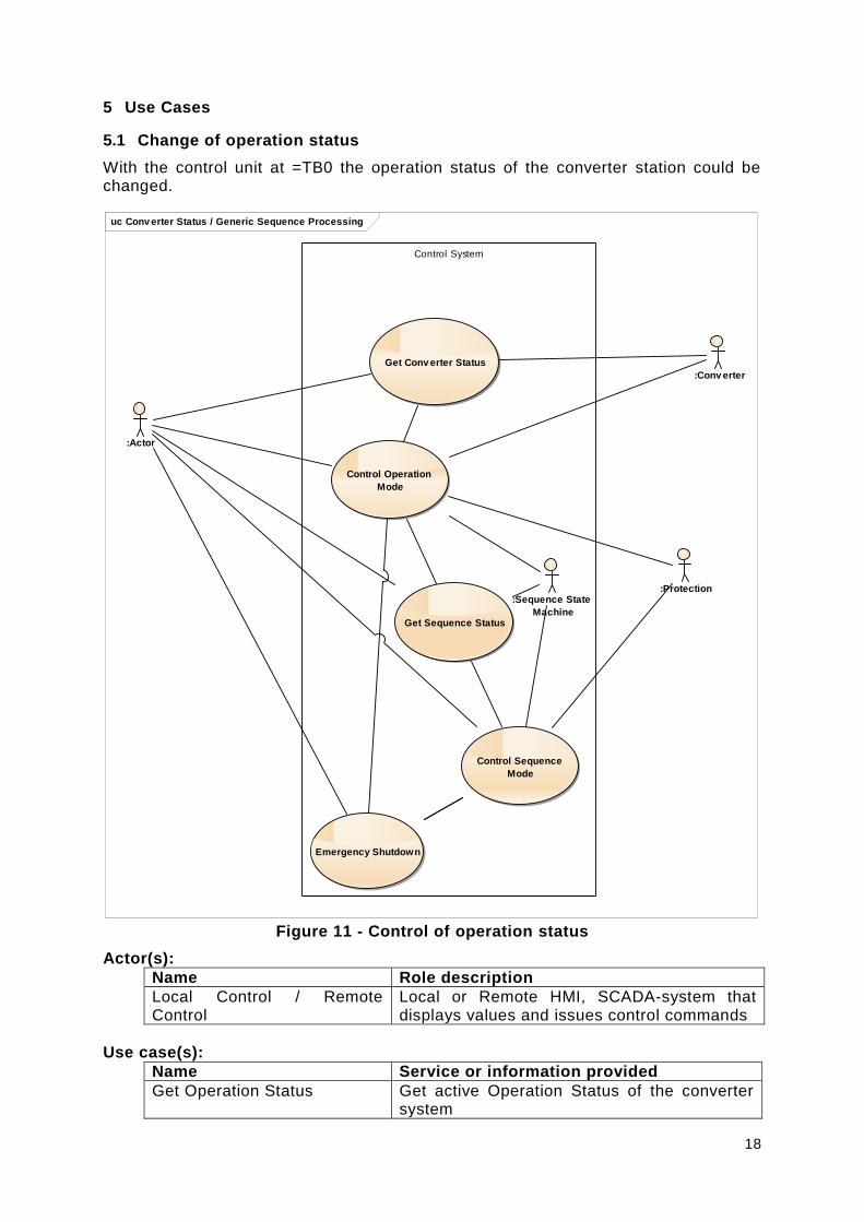
5.1 Change of operation status
With the control unit at =TB0 the operation status of the converter station could be changed.
Figure 11 - Control of operation status
Actor(s):
Name Role description
Local Control / Remote Control
Local or Remote HMI, SCADA-system that displays values and issues control commands
Use case(s):
Name Service or information provided
Get Operation Status Get active Operation Status of the converter system
uc Conv erter Status / Generic Sequence Processing
Control System
Get Conv erter Status
Control Operation
Mode
:Actor
:Conv erter
Get Sequence Status
Control Sequence
Mode
:Sequence State
Machine
:Protection
Emergency Shutdown

19
Control Operation Status Change Operation Status of the converter system
Basic flow:
Get Operation Status
Use Case step
Description
Step 1 Get the current operation status
Step 2 Provide the status to the Local Control / Remote Control
Control Operation Status
Use Case step
Description
Step 1 Local Control / Remote Control sends operation status change request command
Step 2 Operation status change is triggered accordingly
Step 3 Provide the new active Operation status to the Local Control / Remote Control
5.2 Sequence Abort
Actor(s):
Name Role description
Local Control / Remote Control
Local or Remote HMI, SCADA-system that displays values and issues control commands
Use case(s):
Name Service or information provided
Initiate Sequence Abort Abort a running sequence
Basic flow:
Initiate Sequence Abort
Use Case step
Description
Step 1 Local Control / Remote Control sends sequence abort command
Step 2 Abort of running sequence is triggered accordingly
Step 3 Provide the new Sequence Status to the Local Control / Remote Control
5.3 Quick Shutdown
Actor(s):
Name Role description
Local Control / Remote Control
Local or Remote HMI, SCADA-system that displays values and issues control commands
Use case(s):
Name Service or information provided
Initiate Quick Shutdown Initiate Quick Shutdown of the converter station or separate converter unit

20
Basic flow: Initiate Sequence Abort
Use Case step
Description
Step 1 Local Control / Remote Control sends quick shutdown command
Step 2 Quick shutdown triggered accordingly
Step 3 Provide the new Operation Status to the Local Control / Remote Control
5.4 Operation mode
Figure 12 - Operation mode
Actor(s):
Name Role description
Local Control / Remote Control
Local or Remote HMI, SCADA-system that displays values and issues control commands
Use case(s):
Name Service or information provided
Get Operation P-Mode Get active Operation P-Modus of the converter system
Get Operation Q-Mode Get active Operation Q-Modus of the converter system
Control Operation P-Mode Change Operation P-Modus of the converter
Control Operation Q-Mode Change Operation Q-Modus of the converter
Basic flow:
Get Operation P-Modus
Use Case step
Description
Step 1 Get the current operation P-modus
Step 2 Provide the status to the Local Control / Remote Control
uc Activ e/Reactiv e Power Mode Selection
Control System
Control Mode of P-
Control
Control Mode of Q-
Control
:Actor

21
Get Operation Q-Modus
Use Case step
Description
Step 1 Get the current operation Q-modus
Step 2 Provide the status to the Local Control / Remote Control
Control Operation P-Modus
Use Case step
Description
Step 1 Local Control / Remote Control sends operation P-modus change request command
Step 2 Operation P-modus change is triggered accordingly
Step 3 Provide the active Operation P-modus to the Local Control / Remote Control
Control Operation Q-Modus
Use Case step
Description
Step 1 Local Control / Remote Control sends operation Q-modus change request command
Step 2 Operation Q-modus change is triggered accordingly
Step 3 Provide the active Operation Q-modus to the Local Control / Remote Control
5.5 Change of characteristic curve
Figure 13 - Change of characteristic curve
Actor(s):
Name Role description
Local Control / Remote Control
Local or Remote HMI, SCADA-system that displays values and issues control commands
Use case(s):
Name Service or information provided
Get Active Values of P-f-Curve 1
Get active values of characteristic P-f-curve of the converter system
Control Values of P-f-Curve 1 Change values of characteristic P-f-curve of the converter system
Select Active Characteristic Select active characteristic curve of the
uc Activ e Power Control
Control System
:Actor
Control P-Control Settings
uc Reactiv e Power Control
Control System
:ActorControl Q-Control Settings

22
Curve converter
Basic flow:
Get Active Values of P-f-Curve 1
Use Case step
Description
Step 1 Get the Active Values of P-f-Curve 1
Step 2 Provide the Active Values of P-f-Curve 1 to the Local Control / Remote Control
Control Values of P-f-Curve 1
Use Case step
Description
Step 1 Local Control / Remote Control sends new characteristic curve values change request command
Step 2 Change of characteristic curve values is triggered accordingly
Step 3 Provide the active characteristic curve values to the Local Control / Remote Control
Select Active Characteristic Curve
Use Case step
Description
Step 1 Local Control / Remote Control sends selection of active characteristic curve change request command
Step 2 Selection of active characteristic curve change is triggered accordingly
Step 3 Provide the active characteristic curve to the Local Control / Remote Control
5.6 Activate external reference
uc Control by External Reference
Control System
:Actor
Control P-Control
Settings
Control by External
Reference
:External
Reference

23
Figure 14 - External Reference
Actor(s):
Name Role description
Local Control / Remote Control
Local or Remote HMI, SCADA-system that displays values and issues control commands
External Reference Externally provided analogue reference signal
Use case(s):
Name Service or information provided
Activate external reference Activation of the external reference as regulation of the converter unit
Error external reference Error indication of the external reference signal
Basic flow:
Activate external reference
Use Case step
Description
Step 1 Local Control / Remote Control sends activation command for external reference
Step 2 External reference signal is activated accordingly
Step 3 Provide the status of the external reference input to the Local Control / Remote Control
Error external reference
Use Case step
Description
Step 1 External reference Signal is disturbed
Step 2 Provide the disturbance of the external reference signal to the Local Control / Remote Control
24
6 Description of basic modelling approach for IEC 61850
6.1 General
For the further discussion of the IEC 61850 data the top-down-approach is used. Based on the identified applications a non-vendor specific IEC 61850-data model is developed.
If possible existing LNs and DOs are used. But the existing LNs and DOs in IEC 61850-7-4 and IEC 61850-90-7 that contain converter relevant information do not fulfil the requirements to describe the necessary control data for the generic applications shown in chapter 4.4.
The relevant new DOs are described in the following chapters. A complete look at the new LNs and DOs is given in chapter 7.
The results in chapter 4.4 lead to the following modelling conventions.
6.2 Enumerations
Enumerations are used for control and alarm handling. General used values are defined for the enumerations with the naming convention suffix “Kind”. As none of the enumeration values is mandatory by standard, the application required values have to be defined in an SCL file. Application specific extensions of these enumerations are allowed by the standard. Annex A lists the SCL description of the default enumerations.
6.3 Modelling conventions
6.3.1 Measurement
Current, Voltage and Power are allocated to the connection point to the relevant grid and modelled by the LN MMXU.
6.3.2 Supervision
Supervision is modelled with the DO EEHealth and is allocated to the primary components like converter and cooling system.
6.3.3 Protection
Start and trip are allocated to the central component of the transformer or converter .
6.3.4 Control and alarm handling
6.3.4.1 Operation status
The aspect operation status of power converter / FACTS is comparable with the operation status of a circuit breaker. But the components of the generic application have more states than a circuit breaker, because the converter / FACTS application is more complex than circuit breaker application. Besides on and off it is necessary to abort sequences and to have a shut-down-possibility in case of an emergency. The DO OperationSt contains typical states. Additional entries are possible as the CDC ENC is used. (see OperationStKind and SeqStKind)
With EnaOpCmd1 the converter gives remote indications which status can be reached, separate DOs are modelled from CDC SPS. If the DO has the value TRUE the relevant status of the sequence can be reached. For each available state transition there has to be one instance of EnaOpCmd.
25
In Annex C the relevant state-machines are given. They are a proposal to show how the control possibilities can interact. The state-machines have to be adapted for the specific application.
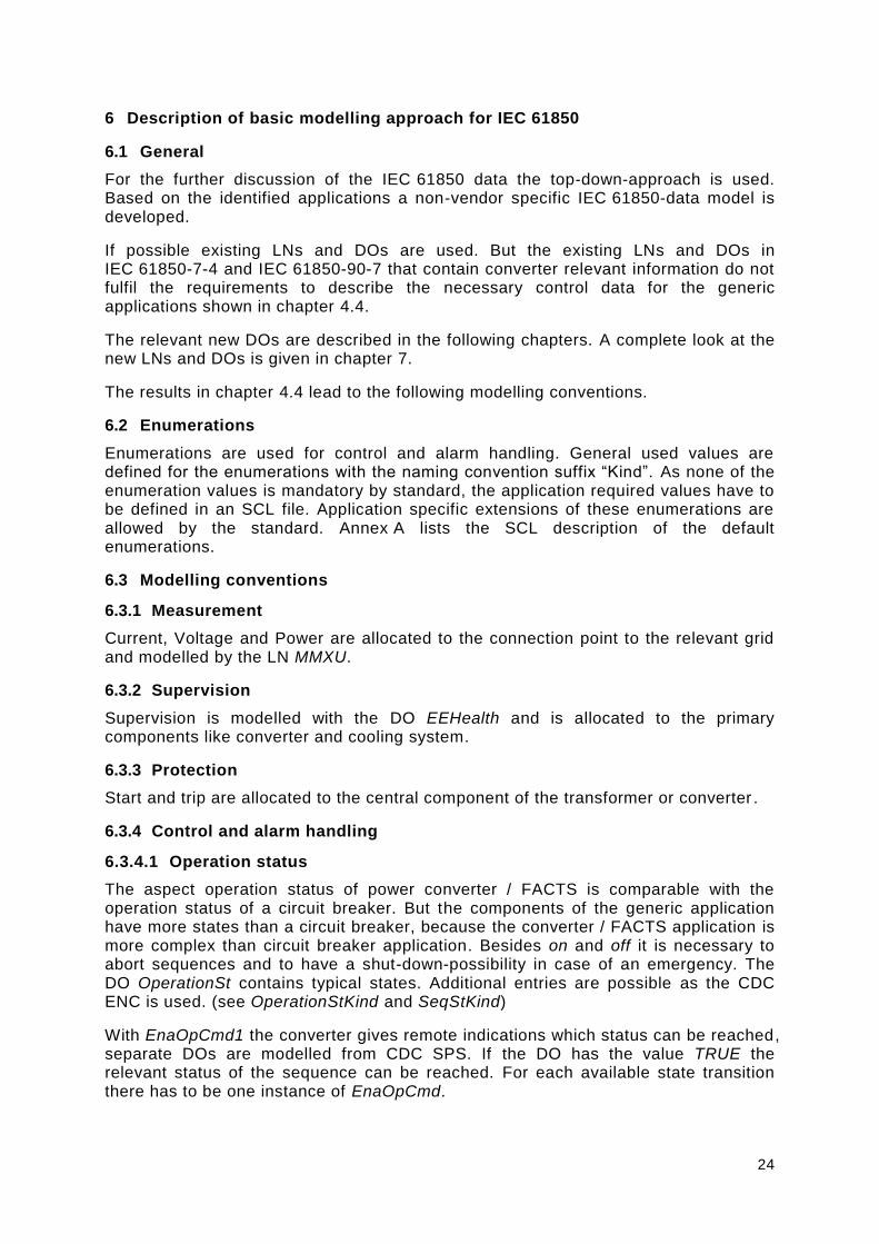
6.3.4.2 Operation mode
The control of the output is done with the operation mode. The following base characteristics are implemented. For all of these operation modes characteristic curves exist. Examples are shown in Annex D.
Table 3 Modelled characteristics
Reference value Controlled value Description
Frequency f Active Power P P = function of f
Voltage V Active Power P P = function of V
Active Power P Fixed P
Frequency f Fixed f
Current I Fixed I
Voltage V Reactive Power Q Q = function of V
Voltage V_min/V_max Reactive Power Q Q = band for V=V_min … V_max
Reactive Power Q Fixed Q
Power factor Phi Fixed Phi
These operation modes are modelled with the DOs ModeP and ModeQ from CDC ENC. Additional modes could be implemented easily.
6.3.5 Description of characteristic curve for converter/FACTS control
The characteristic of each operation mode could be described by two methods:
Characteristic curve is described by array of inflection points (CDC CSG)
Each Reference values is a separate DO from CDC APC
The example shows the P-f-characteristic used at the SFC application. The characteristic curves for the other applications and operation modes can be found in Annex D.

26
Figure 15 - Description of characteristic curve: P-f characteristic
In the case that the characteristic curve is described by an array of the inflection points the clients need the knowledge to interpret the curve the correct way. Not used reference values have to be frozen with the last known value at the client side.
6.3.6 Logical Nodes classes
Chapter 4.2 introduces the components of the generic application model. For transformers and measurements Logical Node classes already exist. For the components of the converter specific LN-classes are introduced:
Table 4 Overview of new logical nodes
LN
name Explanation
[ASEQ] Sequence Control
[CFPC] Control FACTS and Power Conversion Application
[XCON] Primary CONverter
[XDCC] Primary DC Circuit
[MCON] Measurement CONverter
[KFAS] Fire Alarm System
[KBSV] Building SuperVision
[KCGR] Cooling Group
By this new LN classes the information in the considered components are grouped in the relevant LN. This complies with the already existing LN classes for e.g. switchgears and other primary equipment. Converter units as the smallest entities can be flexibly instantiated to meet the specific application technology or system setup.
The complete description of the new Logical Node classes can be found in chapter 7.

27
7 Description of new LNs, DOs, Enumerations
For the generic application model the following Logical Node classes, Data Objects and Enumerations are necessary. Figure 16 shows the overview of the UML model for the introduced or extended elements.
Figure 16 - Overview of UML model
class IEC61850_90_14
DOEnums_90_14
+ ChaDCStKind
+ ConfDCStKind
+ ConnDCStKind
+ GenDCStKind
+ ModPKind
+ ModQKind
+ OperationCmdKind
+ OperationStKind
+ SeqStKind
+ DetailedDiagrams
Logica lNodes_90_14
+ LNGroupA
+ LNGroupC
+ LNGroupK
+ LNGroupM
+ LNGroupX
IEC61850_90_14Namespace
+ date: P_VisString64 = 2016-03-15 {readOnly}
+ id: P_VisString64 = DKE 61850-90-14 {readOnly}
+ revision: P_VisString64 = A {readOnly}
+ tissuesApplied: P_VisString255 {readOnly}
+ version: P_VisString64 = 2016 {readOnly}
Abbr ev ia t ions_90_14
+ Abbreviations_90_14
Der iv edDAs_90_14 Der iv edCDCs_90_14
+ ENCGenDCSt
+ ENCModP
+ ENCModQ
+ ENCOperationCmd
+ ENSChaDCSt
+ ENSConfDCSt
+ ENSConnDCSt
+ ENSOperationSt
+ ENSSeqSt

28
7.1 Enumerations
7.1.1 General
Figure 17 - UML model of the enumerations
Figure 18 - UML model of the derived CDCs
class DOEnums_90_14
«enumeration»
DOEnums_90_14::
Oper a t ionStK ind
Tripped = 1
Off_Earthed = 2
Off_Isolated = 3
Off = 4
Standby = 5
On = 6
On_Testing = 7
On_Islanded = 8
«enumeration»
DOEnums_90_14::
Oper a t ionCmdKind
Off_Earthed = 1
Off_Isolated = 2
Off = 3
Standby = 4
On = 5
On_Testing = 6
On_Islanded = 7
«enumeration»
DOEnums_90_14::
GenDCStK ind
Demand = 1
Generation = 2
«enumeration»
DOEnums_90_14::
SeqStK ind
Sequence_Off = 1
Sequence_On = 2
Sequence_Aborted = 3
«enumeration»
DOEnums_90_14::
ModQKind
None = 0
Q_V_operation = 1
Q_Fixed = 2
Q_Band = 3
Phi_Fixed = 4
FlickerCtl = 5
«enumeration»
DOEnums_90_14::
ModPK ind
None = 0
P_f_operation = 1
P_V_operation = 2
P_fixed = 3
f_coupled = 4
Amp_fixed = 5
P_DCVol_operation = 6
«enumeration»
DOEnums_90_14::
ChaDCStK ind
Charging = 1
Charged = 2
Discharging = 3
Discharged = 4
«enumeration»
DOEnums_90_14::
ConnDCStK ind
DC_Connected = 1
DC_Isolated = 2
DC_Isolated_Grounded = 3
«enumeration»
DOEnums_90_14::
ConfDCStK ind
Bipole = 1
RigidBipole = 2
GroundDMRReturn = 3
MetallicHVReturn = 4
ParallelReturn = 5
HVLOpReturn = 6
OLT = 7
class Der iv edCDCs_90_14
existing (standard 7-4)
ENSOper a t ionSt
SubstitutionCDC
CDCSta tusInfo::ENS
ENCOper a t ionCmd
ControlTestingCDC
CDCContr ol::ENC
ENCGenDCSt
ENSSeqSt ENCModQENCModP
ENSChaDCSt ENSConnDCStENSConfDCSt

29
7.1.2 Charge DC status (ChaDCStKind enumeration)
Component charging status.
Table 5 shows all enumeration items of ChaDCStKind.
Table 5 – Literals of ChaDCStKind
ChaDCStKind
enumeration item value description
Charging 1 Component is charging
Charged 2 Component is charged
Discharging 3 Component is discharging
Discharged 4 Component is discharged
7.1.3 Configuration DC status (ConfDCStKind enumeration)
The DC yard configuration.
Table 6 shows all enumeration items of ConfDCStKind.
Table 6 – Literals of ConfDCStKind
ConfDCStKind
enumeration item value description
Bipole 1 DC Yard Bipole Configuration
RigidBipole 2 DC Yard Rigid Bipole Configuration
GroundDMRReturn 3 DC Yard Ground/Dedicated Metallic Return Configuration
MetallicHVReturn 4 DC Yard Metallic/High Voltage Return Configuration
ParallelReturn 5 DC Yard Parallel Return Configuration
HVLOpReturn 6 DC Yard High Voltage Line Other Pole Return Configuration
OLT 7 DC Yard Open Line Test Configuration
7.1.4 Connection DC status (ConnDCStKind enumeration)
The status of the DC connection.
Table 7 shows all enumeration items of ConnDCStKind.
Table 7 – Literals of ConnDCStKind
ConnDCStKind
enumeration item value description
DC_Connected 1 Converter Connected to DC Circuit
DC_Isolated 2 Converter Isolated from DC Circuit
30
ConnDCStKind
enumeration item value description
DC_Isolated_Grounded 3 Converter Isolated from DC Circuit and grounded
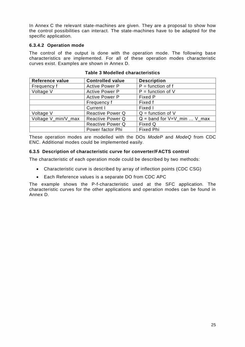
7.1.5 Generation DC status (GenDCStKind enumeration)
The status of the DC generation.
Table 8 shows all enumeration items of GenDCStKind.
Table 8 – Literals of GenDCStKind
GenDCStKind
enumeration item value description
Demand 1 Active Power Consumption ("Rectifier") / Import from power grid / Demand
Generation 2 Active Power Generation ("Inverter") / Export to power grid / Generation
7.1.6 Mode P (ModPKind enumeration)
Modus of active power control.
Table 9 shows all enumeration items of ModPKind.
Table 9 – Literals of ModPKind
ModPKind
enumeration item value description
None 0 No characteristic is active
P_f_operation 1 P = function of f according characteristic via curve
P_V_operation 2 P = function of V according characteristic via curve
P_fixed 3 P = P_fixed
f_coupled 4 f = f_coupled
Amp_fixed 5 I = AmpFix, I-Mode / Current Control I-Mode
P_DCVol_operation 6 P = function of DC voltage
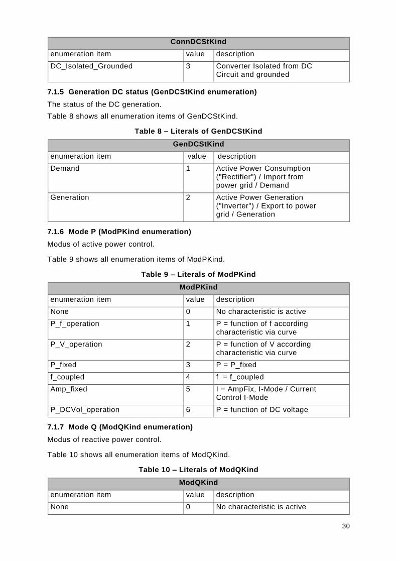
7.1.7 Mode Q (ModQKind enumeration)
Modus of reactive power control.
Table 10 shows all enumeration items of ModQKind.
Table 10 – Literals of ModQKind
ModQKind
enumeration item value description
None 0 No characteristic is active
31
ModQKind
enumeration item value description
Q_V_operation 1 Q = function of V according characteristic via curve
Q_Fixed 2 Q = Q_Fixed
Q_Band 3 Q = Q_band for V=V_min … V_max
Phi_Fixed 4 Phi = fixed
FlickerCtl 5 Compensation of flickers
7.1.8 Operation command (OperationCmdKind enumeration)
Command to control converter.
Table 11 shows all enumeration items of OperationCmdKind.
Table 11 – Literals of OperationCmdKind
OperationCmdKind
enumeration item value description
Off_Earthed 1 Off and earthed.
Off_Isolated 2 Off and isolated.
Off 3 Off.
Standby 4 Standby.
On 5 Regular on.
On_Testing 6 On for testing.
On_Islanded 7 On and islanded.
7.1.9 Operation Status (OperationStKind enumeration)
Operation status of the converter.
Table 12 shows all enumeration items of OperationStKind.
Table 12 – Literals of OperationStKind
OperationStKind
enumeration item value description
Tripped 1 Tripped
Off_Earthed 2 Off and earthed
Off_Isolated 3 Off and isolated
Off 4 Off
Standby 5 Standby
On 6 Regular on.
On_Testing 7 On for testing.
On_Islanded 8 On and islanded
7.1.10 Sequencer status (SeqStKind enumeration)
The status of the sequencer.

32
Table 13 shows all enumeration items of SeqStKind.
Table 13 – Literals of SeqStKind
SeqStKind
enumeration item value description
Sequence_Off 1 Sequence is not running.
Sequence_On 2 Sequence is running.
Sequence_Aborted 3 sequence is not running, running sequence has been aborted.
7.2 New or extended classes
7.2.1 General
Figure 19 – Class diagram LogicalNodes_90_14::LogicalNodes_90_14
class Logica lNodes_90_14
LNGr oupA
+ ASEQ
LNGr oupC
+ CFPC
LNGr oupK
+ KBSV
+ KCGR
+ KFAS
LNGr oupM
+ MCON
LNGr oupX
+ XCON
+ XDCC

33
7.2.2 Package LNGroupA
7.2.2.1 General
Figure 20 – Class diagram LNGroupA::LNGroupANew
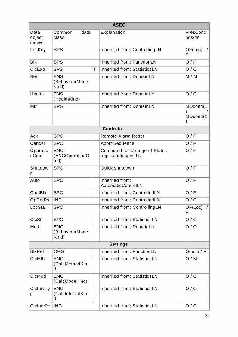
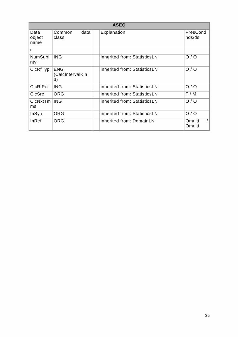
7.2.2.2 ASEQ LN
The role of this logical node is to provide information regarding sequences of actions during startup or stopping of a function.
Table 14 shows all data objects of ASEQ.
Table 14 – Data objects of ASEQ
ASEQ
Data object name
Common data class
T Explanation PresCond nds/ds
Descriptions
NamPlt LPL inherited from: DomainLN O / O
Status information
EnaOpCmd1
SPS Operation Command 1 enable O / F
OperationSt
ENS (ENSOperationSt)
State of application: application specific
O / F
SeqSt ENS (ENSSeqSt)
no sequence, sequence running, sequence aborted
O / F
Loc SPS inherited from: ControllingLN O / F
cla ss LNGr oupANew
existing (standard 7-4)
ASEQ
+ Ack: SPC [0..1]
+ Cancel: SPC [0..1]
+ EnaOpCmd1: SPS [0..1]
+ OperationCmd: ENCOperationCmd [0..1]
+ OperationSt: ENSOperationSt [0..1]
+ SeqSt: ENSSeqSt [0..1]
+ Shutdown: SPC [0..1]
ControlledLN
Abstr actLNsCommon::Automat icContr olLN
34
ASEQ
Data object name
Common data class
T Explanation PresCond nds/ds
LocKey SPS inherited from: ControllingLN OF(Loc) / F
Blk SPS inherited from: FunctionLN O / F
ClcExp SPS T inherited from: StatisticsLN O / O
Beh ENS (BehaviourModeKind)
inherited from: DomainLN M / M
Health ENS (HealthKind)
inherited from: DomainLN O / O
Mir SPS inherited from: DomainLN MOcond(1) / MOcond(1)
Controls
Ack SPC Remote Alarm Reset O / F
Cancel SPC Abort Sequence O / F
OperationCmd
ENC (ENCOperationCmd)
Command for Change of State : application specific
O / F
Shutdown
SPC Quick shutdown O / F
Auto SPC inherited from: AutomaticControlLN
O / F
CmdBlk SPC inherited from: ControlledLN O / F
OpCntRs INC inherited from: ControlledLN O / O
LocSta SPC inherited from: ControllingLN OF(Loc) / F
ClcStr SPC inherited from: StatisticsLN O / O
Mod ENC (BehaviourModeKind)
inherited from: DomainLN O / O
Settings
BlkRef ORG inherited from: FunctionLN Omulti / F
ClcMth ENG (CalcMethodKind)
inherited from: StatisticsLN O / M
ClcMod ENG (CalcModeKind)
inherited from: StatisticsLN O / O
ClcIntvTyp
ENG (CalcIntervalKind)
inherited from: StatisticsLN O / O
ClcIntvPe ING inherited from: StatisticsLN O / O
35
ASEQ
Data object name
Common data class
T Explanation PresCond nds/ds
r
NumSubIntv
ING inherited from: StatisticsLN O / O
ClcRfTyp ENG (CalcIntervalKind)
inherited from: StatisticsLN O / O
ClcRfPer ING inherited from: StatisticsLN O / O
ClcSrc ORG inherited from: StatisticsLN F / M
ClcNxtTmms
ING inherited from: StatisticsLN O / O
InSyn ORG inherited from: StatisticsLN O / O
InRef ORG inherited from: DomainLN Omulti / Omulti

36
7.2.3 Package LNGroupC
7.2.3.1 General
Figure 21 – Class diagram LNGroupC::LNGroupCNew
cla ss LNGr oupCNew
existing (standard 7-4)
CFPC
+ AlmRefInp: SPS [0..1]
+ DCAmpFix: APC [0..1]
+ DCAmpRmpRte: APC [0..1]
+ DCVolFix: APC [0..1]
+ EnaExtDev: SPC [0..1]
+ FRefA: APC [0..1]
+ FRefB: APC [0..1]
+ FRefC: APC [0..1]
+ FRefD: APC [0..1]
+ Gain: APC [0..1]
+ GenDCSt: ENCGenDCSt [0..1]
+ GradNA: APC [0..1]
+ GradNB: APC [0..1]
+ GradNC: APC [0..1]
+ GradND: APC [0..1]
+ HldOnOpPt: SPC [0..1]
+ IslOp: SPS [0..1]
+ MasterSt: SPS [0..1]
+ ModP: ENCModP [0..1]
+ ModQ: ENCModQ [0..1]
+ OperationBlk: SPS [0..1]
+ PfCrv1: CSG [0..1]
+ PfCrvSet1: CSG [0..1]
+ PFix: APC [0..1]
+ PFixMax: APC [0..1]
+ PFixMin: APC [0..1]
+ PhiRmpRte: APC [0..1]
+ PMaxG: APC [0..1]
+ PMaxL: APC [0..1]
+ PRangeExd: SPS [0..1]
+ PRmpRte: APC [0..1]
+ PRmptms: APC [0..1]
+ PVCrv: CSG [0..1]
+ PVCrvSet: CSG [0..1]
+ PVRef: APC [0..1]
+ QBnd: APC [0..1]
+ QFix: APC [0..1]
+ QGradNA: APC [0..1]
+ QGradNB: APC [0..1]
+ QGradNC: APC [0..1]
+ QMaxC: APC [0..1]
+ QMaxI: APC [0..1]
+ QPhiFix: APC [0..1]
+ QRangeExd: SPS [0..1]
+ QRmpRte: APC [0..1]
+ QVCrv: CSG [0..1]
+ QVCrvSet: CSG [0..1]
+ QVRef: APC [0..1]
+ RefExtOn: SPC [0..1]
+ RndPwrDCOn: SPC [0..1]
+ SelPfCrv: INC [0..1]
+ SetDefault: SPC [0..1]
+ Slope: APC [0..1]
+ Vmax: APC [0..1]
+ Vmin: APC [0..1]
ControllingLN
Abstr actLNsCommon::Contr ol ledLN

37
7.2.3.2 CFPC LN
Table 15 shows all data objects of CFPC.
Table 15 – Data objects of CFPC
CFPC
Data object name
Common data class
T Explanation PresCond nds/ds
Descriptions
NamPlt LPL inherited from: DomainLN O / O
Status information
AlmRefInp
SPS Reference value disturbed O / F
IslOp SPS Island operation active O / F
MasterSt SPS True: Component is Master, False : Component is Slave
O / F
OperationBlk
SPS Blocking active O / F
PRangeExd
SPS Rated range P exceeded O / F
QRangeExd
SPS Rated range Q exceeded O / F
Loc SPS inherited from: ControllingLN O / F
LocKey SPS inherited from: ControllingLN OF(Loc) / F
Blk SPS inherited from: FunctionLN O / F
ClcExp SPS T inherited from: StatisticsLN O / O
Beh ENS (BehaviourModeKind)
inherited from: DomainLN M / M
Health ENS (HealthKind)
inherited from: DomainLN O / O
Mir SPS inherited from: DomainLN MOcond(1) / MOcond(1)
Controls
DCAmpFix
APC reference value DC Current Fix O / O
DCAmpRmpRte
APC ramp rate for change of DC Current [A/s]
O / O
DCVolFix APC reference value DC Voltage Setpoint
O / O
EnaExtDev
SPC TRUE: control of external devices by converter is enabled;
O / F

38
CFPC
Data object name
Common data class
T Explanation PresCond nds/ds
FALSE: control of external devices by converter is disabled
FRefA APC reference value FRefA [Hz] O / O
FRefB APC reference value FRefB [Hz] O / O
FRefC APC reference value FRefC [Hz] O / O
FRefD APC reference value FRefD [Hz] O / O
Gain APC parameter Gain for V-control O / O
GenDCSt ENC (ENCGenDCSt)
Demand(Rectifier) , Generation(Inverter).
O / F
GradNA APC reference value GradNA [] O / O
GradNB APC reference value GradNB [] O / O
GradNC APC reference value GradNC [] O / O
GradND APC reference value GradND [] O / O
HldOnOpPt
SPC Hold On of Operation Point = TRUE: Operation point is helt on, FALSE: Operation Point is defined according characteristik
O / F
ModP ENC (ENCModP) P-Mode: P_f_operation, P_V_operation, P_fixed, f_coupled, Amp_fixed, P_DCVol_operation
O / F
ModQ ENC (ENCModQ) Q-Mode: Q_V_operation, Q_Fixed, Q_Band, Phi_Fixed, FlickerCtl
O / F
PFix APC reference value PFix [MW] O / O
PFixMax APC reference value PFixMax [MW] O / O
PFixMin APC reference value PFixMin [MW] O / O
PhiRmpRte
APC ramp rate for change of Phi [grd/s]
O / O
PMaxG APC reference value PMaxG [MW] O / O
PMaxL APC reference value PMaxL [MW] O / O
PRmpRte APC ramp rate for change of P [MW/s]
O / O
PRmptms APC time intervall for change of P [s] O / O
PVRef APC reference value VRef [kV] O / O
QBnd APC reference value QBand [MVar] O / O
QFix APC reference value QFix [MVar] O / O
QGradNA APC reference value QGradNA [] O / O
QGradNB APC reference value QGradNB [] O / O
QGradN APC reference value QGradNC [] O / O

39
CFPC
Data object name
Common data class
T Explanation PresCond nds/ds
C
QMaxC APC reference value QMaxC [MVAr] O / O
QMaxI APC reference value QMaxI [MVAr] O / O
QPhiFix APC reference value PhiFix [] O / O
QRmpRte
APC ramp rate for change of Q [MVAr/s]
O / O
QVRef APC reference value QVRef [kV] O / O
RefExtOn SPC TRUE : control by external reference, FALSE : control by own reference
O / F
RndPwrDCOn
SPC TRUE : Round Power Mode ON (both Poles different Power Direction),
FALSE : Round Power Mode OFF (both Poles same Power Direction)
O / F
SelPfCrv INC Select Characteristic display Pf: 1 - Select OpPfCurveSet1, 2 - Select OpPfCurveSet2
O / O
SetDefault
SPC TRUE: Settings are set to default
O / F
Slope APC parameter Slope for V-control O / O
Vmax APC reference value VMax [kV] O / O
Vmin APC reference value VMin [kV] O / O
CmdBlk SPC inherited from: ControlledLN O / F
OpCntRs INC inherited from: ControlledLN O / O
LocSta SPC inherited from: ControllingLN OF(Loc) / F
ClcStr SPC inherited from: StatisticsLN O / O
Mod ENC (BehaviourModeKind)
inherited from: DomainLN O / O
Settings
PfCrv1 CSG Characteristic display 1 Pf Active values P [MW], f [Hz] absolute
O / F
PfCrvSet1
CSG Characteristic display 1 Pf Control direction P [MW], f [Hz] absolute
O / F
PVCrv CSG Characteristic display PV Active values P [MW], U [kV]
O / F
PVCrvSet CSG Characteristic display PV Control direction P [MW], U [kV]
O / F

40
CFPC
Data object name
Common data class
T Explanation PresCond nds/ds
QVCrv CSG Characteristic display Q Active values Q [MVAr], U [kV]
O / F
QVCrvSet
CSG Characteristic display Q Control direction: Q [MVAr], U [kV]
O / F
BlkRef ORG inherited from: FunctionLN Omulti / F
ClcMth ENG (CalcMethodKind)
inherited from: StatisticsLN O / M
ClcMod ENG (CalcModeKind)
inherited from: StatisticsLN O / O
ClcIntvTyp
ENG (CalcIntervalKind)
inherited from: StatisticsLN O / O
ClcIntvPer
ING inherited from: StatisticsLN O / O
NumSubIntv
ING inherited from: StatisticsLN O / O
ClcRfTyp ENG (CalcIntervalKind)
inherited from: StatisticsLN O / O
ClcRfPer ING inherited from: StatisticsLN O / O
ClcSrc ORG inherited from: StatisticsLN F / M
ClcNxtTmms
ING inherited from: StatisticsLN O / O
InSyn ORG inherited from: StatisticsLN O / O
InRef ORG inherited from: DomainLN Omulti / Omulti

41
7.2.4 Package LNGroupK
7.2.4.1 General
Figure 22 – Class diagram LNGroupK::LNGroupKNew
7.2.4.2 KBSV LN
Plant safety
Table 16 shows all data objects of KBSV.
Table 16 – Data objects of KBSV
KBSV
Data object name
Common data class
T Explanation PresCond nds/ds
Descriptions
EEName DPL inherited from: ControlEquipmentInterfaceLN
O / F
NamPlt LPL inherited from: DomainLN O / O
EEName DPL inherited from: EquipmentInterfaceLN O / F
Status information
StaShielded
SPS Plant operator safety ok O / F
StaStaffed
SPS Plant manned O / F
EEHealth ENS (HealthKind)
inherited from: ControlEquipmentInterfaceLN
O / F
OpTmh INS inherited from: ControlEquipmentInterfaceLN
O / O
Loc SPS inherited from: ControllingLN O / F
LocKey SPS inherited from: ControllingLN OF(Loc) / F
class LNGr oupKNew
existing (standard 7-4)
KBSV
+ StaShielded: SPS [0..1]
+ StaStaffed: SPS [0..1]
KCGR
FunctionLN
Abstr actLNsCommon::Equipment Inter fa ceLN
+ EEHealth: ENSHealth [0..1]
+ EEName: DPL [0..1]
+ OpTmh: INS [0..1]
KFAS
+ Alm: SPS [0..1]

42
KBSV
Data object name
Common data class
T Explanation PresCond nds/ds
Blk SPS inherited from: FunctionLN O / F
ClcExp SPS T inherited from: StatisticsLN O / O
Beh ENS (BehaviourModeKind)
inherited from: DomainLN M / M
Health ENS (HealthKind)
inherited from: DomainLN O / O
Mir SPS inherited from: DomainLN MOcond(1) / MOcond(1)
EEHealth ENS (HealthKind)
inherited from: EquipmentInterfaceLN O / F
OpTmh INS inherited from: EquipmentInterfaceLN O / O
Controls
CmdBlk SPC inherited from: ControlledLN O / F
OpCntRs INC inherited from: ControlledLN O / O
LocSta SPC inherited from: ControllingLN OF(Loc) / F
ClcStr SPC inherited from: StatisticsLN O / O
Mod ENC (BehaviourModeKind)
inherited from: DomainLN O / O
Settings
BlkRef ORG inherited from: FunctionLN Omulti / F
ClcMth ENG (CalcMethodKind)
inherited from: StatisticsLN O / M
ClcMod ENG (CalcModeKind)
inherited from: StatisticsLN O / O
ClcIntvTyp
ENG (CalcIntervalKind)
inherited from: StatisticsLN O / O
ClcIntvPer
ING inherited from: StatisticsLN O / O
NumSubIntv
ING inherited from: StatisticsLN O / O
ClcRfTyp ENG (CalcIntervalKind)
inherited from: StatisticsLN O / O
ClcRfPer ING inherited from: StatisticsLN O / O
ClcSrc ORG inherited from: StatisticsLN F / M
43
KBSV
Data object name
Common data class
T Explanation PresCond nds/ds
ClcNxtTmms
ING inherited from: StatisticsLN O / O
InSyn ORG inherited from: StatisticsLN O / O
InRef ORG inherited from: DomainLN Omulti / Omulti
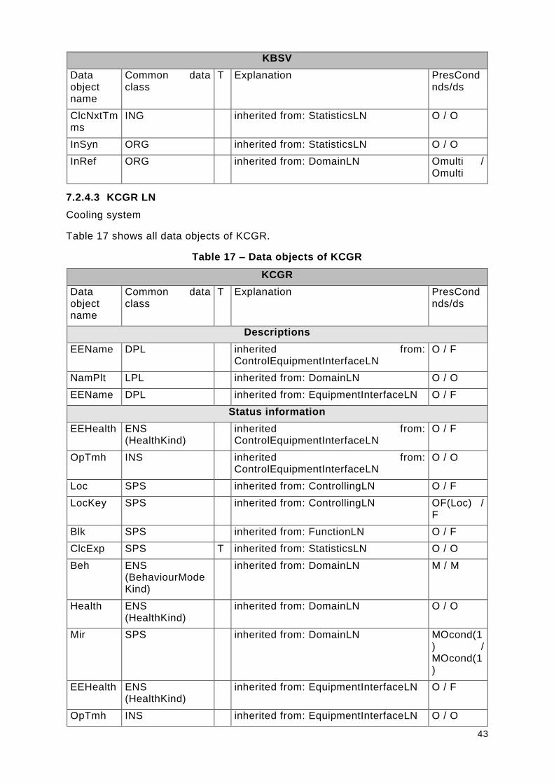
7.2.4.3 KCGR LN
Cooling system
Table 17 shows all data objects of KCGR.
Table 17 – Data objects of KCGR
KCGR
Data object name
Common data class
T Explanation PresCond nds/ds
Descriptions
EEName DPL inherited from: ControlEquipmentInterfaceLN
O / F
NamPlt LPL inherited from: DomainLN O / O
EEName DPL inherited from: EquipmentInterfaceLN O / F
Status information
EEHealth ENS (HealthKind)
inherited from: ControlEquipmentInterfaceLN
O / F
OpTmh INS inherited from: ControlEquipmentInterfaceLN
O / O
Loc SPS inherited from: ControllingLN O / F
LocKey SPS inherited from: ControllingLN OF(Loc) / F
Blk SPS inherited from: FunctionLN O / F
ClcExp SPS T inherited from: StatisticsLN O / O
Beh ENS (BehaviourModeKind)
inherited from: DomainLN M / M
Health ENS (HealthKind)
inherited from: DomainLN O / O
Mir SPS inherited from: DomainLN MOcond(1) / MOcond(1)
EEHealth ENS (HealthKind)
inherited from: EquipmentInterfaceLN O / F
OpTmh INS inherited from: EquipmentInterfaceLN O / O

44
KCGR
Data object name
Common data class
T Explanation PresCond nds/ds
Controls
CmdBlk SPC inherited from: ControlledLN O / F
OpCntRs INC inherited from: ControlledLN O / O
LocSta SPC inherited from: ControllingLN OF(Loc) / F
ClcStr SPC inherited from: StatisticsLN O / O
Mod ENC (BehaviourModeKind)
inherited from: DomainLN O / O
Settings
BlkRef ORG inherited from: FunctionLN Omulti / F
ClcMth ENG (CalcMethodKind)
inherited from: StatisticsLN O / M
ClcMod ENG (CalcModeKind)
inherited from: StatisticsLN O / O
ClcIntvTyp
ENG (CalcIntervalKind)
inherited from: StatisticsLN O / O
ClcIntvPer
ING inherited from: StatisticsLN O / O
NumSubIntv
ING inherited from: StatisticsLN O / O
ClcRfTyp ENG (CalcIntervalKind)
inherited from: StatisticsLN O / O
ClcRfPer ING inherited from: StatisticsLN O / O
ClcSrc ORG inherited from: StatisticsLN F / M
ClcNxtTmms
ING inherited from: StatisticsLN O / O
InSyn ORG inherited from: StatisticsLN O / O
InRef ORG inherited from: DomainLN Omulti / Omulti
7.2.4.4 KFAS LN
Fire alarm system
Table 18 shows all data objects of KFAS.
Table 18 – Data objects of KFAS
KFAS

45
Data object name
Common data class
T Explanation PresCond nds/ds
Descriptions
EEName DPL inherited from: EquipmentInterfaceLN O / F
NamPlt LPL inherited from: DomainLN O / O
Status information
Alm SPS Fire Alarm O / F
EEHealth ENS (HealthKind)
inherited from: EquipmentInterfaceLN O / F
OpTmh INS inherited from: EquipmentInterfaceLN O / O
Blk SPS inherited from: FunctionLN O / F
ClcExp SPS T inherited from: StatisticsLN O / O
Beh ENS (BehaviourModeKind)
inherited from: DomainLN M / M
Health ENS (HealthKind)
inherited from: DomainLN O / O
Mir SPS inherited from: DomainLN MOcond(1) / MOcond(1)
Controls
ClcStr SPC inherited from: StatisticsLN O / O
Mod ENC (BehaviourModeKind)
inherited from: DomainLN O / O
Settings
BlkRef ORG inherited from: FunctionLN Omulti / F
ClcMth ENG (CalcMethodKind)
inherited from: StatisticsLN O / M
ClcMod ENG (CalcModeKind)
inherited from: StatisticsLN O / O
ClcIntvTyp
ENG (CalcIntervalKind)
inherited from: StatisticsLN O / O
ClcIntvPer
ING inherited from: StatisticsLN O / O
NumSubIntv
ING inherited from: StatisticsLN O / O
ClcRfTyp ENG (CalcIntervalKind)
inherited from: StatisticsLN O / O
ClcRfPer ING inherited from: StatisticsLN O / O
ClcSrc ORG inherited from: StatisticsLN F / M
46
KFAS
Data object name
Common data class
T Explanation PresCond nds/ds
ClcNxtTmms
ING inherited from: StatisticsLN O / O
InSyn ORG inherited from: StatisticsLN O / O
InRef ORG inherited from: DomainLN Omulti / Omulti
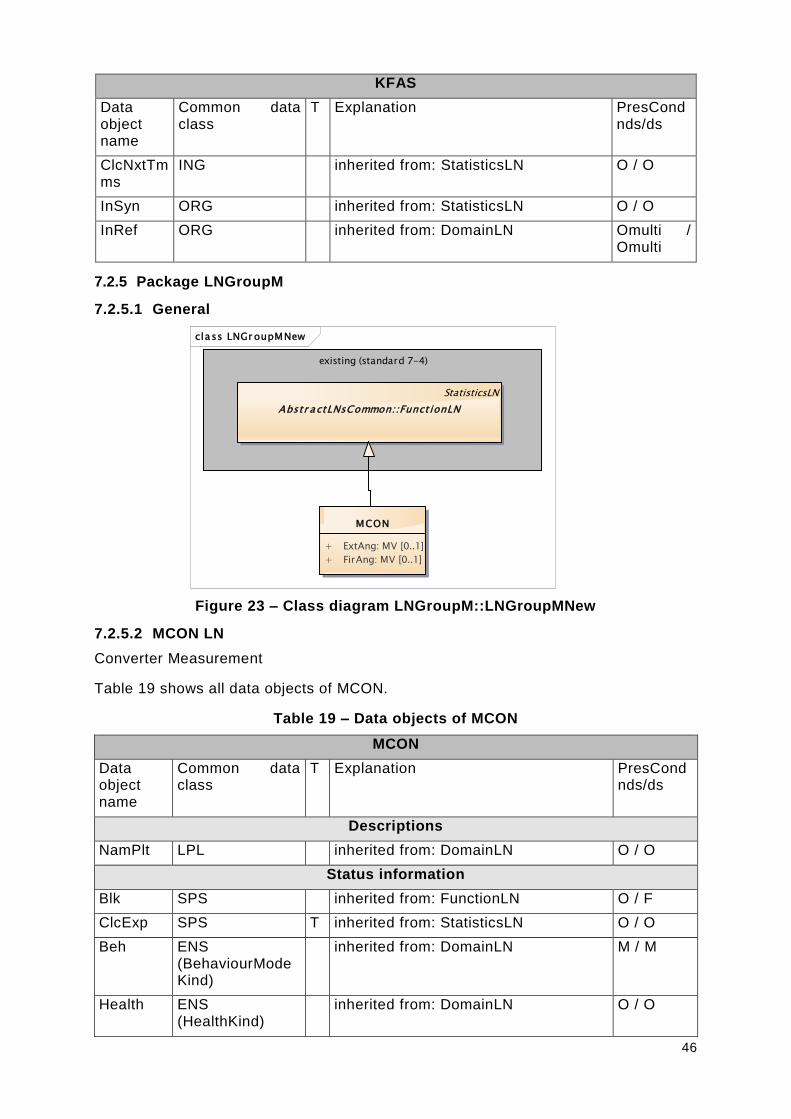
7.2.5 Package LNGroupM
7.2.5.1 General
Figure 23 – Class diagram LNGroupM::LNGroupMNew
7.2.5.2 MCON LN
Converter Measurement
Table 19 shows all data objects of MCON.
Table 19 – Data objects of MCON
MCON
Data object name
Common data class
T Explanation PresCond nds/ds
Descriptions
NamPlt LPL inherited from: DomainLN O / O
Status information
Blk SPS inherited from: FunctionLN O / F
ClcExp SPS T inherited from: StatisticsLN O / O
Beh ENS (BehaviourModeKind)
inherited from: DomainLN M / M
Health ENS (HealthKind)
inherited from: DomainLN O / O
cla ss LNGr oupMNew
existing (standard 7-4)
StatisticsLN
Abstr actLNsCommon::Funct ionLN
MCON
+ ExtAng: MV [0..1]
+ FirAng: MV [0..1]

47
MCON
Data object name
Common data class
T Explanation PresCond nds/ds
Mir SPS inherited from: DomainLN MOcond(1) / MOcond(1)
Measured and metered values
ExtAng MV Converter Valve Extinction Angle O / O
FirAng MV Converter Valve Firing Angle O / O
Controls
ClcStr SPC inherited from: StatisticsLN O / O
Mod ENC (BehaviourModeKind)
inherited from: DomainLN O / O
Settings
BlkRef ORG inherited from: FunctionLN Omulti / F
ClcMth ENG (CalcMethodKind)
inherited from: StatisticsLN O / M
ClcMod ENG (CalcModeKind)
inherited from: StatisticsLN O / O
ClcIntvTyp
ENG (CalcIntervalKind)
inherited from: StatisticsLN O / O
ClcIntvPer
ING inherited from: StatisticsLN O / O
NumSubIntv
ING inherited from: StatisticsLN O / O
ClcRfTyp ENG (CalcIntervalKind)
inherited from: StatisticsLN O / O
ClcRfPer ING inherited from: StatisticsLN O / O
ClcSrc ORG inherited from: StatisticsLN F / M
ClcNxtTmms
ING inherited from: StatisticsLN O / O
InSyn ORG inherited from: StatisticsLN O / O
InRef ORG inherited from: DomainLN Omulti / Omulti
MCON
Data object name
Common data class
T Explanation PresCond nds/ds
Descriptions
NamPlt LPL inherited from: DomainLN O / O

48
MCON
Data object name
Common data class
T Explanation PresCond nds/ds
Status information
Blk SPS inherited from: FunctionLN O / F
ClcExp SPS T inherited from: StatisticsLN O / O
Beh ENS (BehaviourModeKind)
inherited from: DomainLN M / M
Health ENS (HealthKind)
inherited from: DomainLN O / O
Mir SPS inherited from: DomainLN MOcond(1) / MOcond(1)
Controls
ClcStr SPC inherited from: StatisticsLN O / O
Mod ENC (BehaviourModeKind)
inherited from: DomainLN O / O
Settings
BlkRef ORG inherited from: FunctionLN Omulti / F
ClcMth ENG (CalcMethodKind)
inherited from: StatisticsLN O / M
ClcMod ENG (CalcModeKind)
inherited from: StatisticsLN O / O
ClcIntvTyp
ENG (CalcIntervalKind)
inherited from: StatisticsLN O / O
ClcIntvPer
ING inherited from: StatisticsLN O / O
NumSubIntv
ING inherited from: StatisticsLN O / O
ClcRfTyp ENG (CalcIntervalKind)
inherited from: StatisticsLN O / O
ClcRfPer ING inherited from: StatisticsLN O / O
ClcSrc ORG inherited from: StatisticsLN F / M
ClcNxtTmms
ING inherited from: StatisticsLN O / O
InSyn ORG inherited from: StatisticsLN O / O
InRef ORG inherited from: DomainLN Omulti / Omulti

49
7.2.6 Package LNGroupX
7.2.6.1 General
Figure 24 – Class diagram LNGroupX::LNGroupXNew
7.2.6.2 XCON LN
Converter
Table 20 shows all data objects of XCON.
Table 20 – Data objects of XCON
XCON
Data object name
Common data class
T Explanation PresCond nds/ds
Descriptions
EEName DPL inherited from: EquipmentInterfaceLN O / F
NamPlt LPL inherited from: DomainLN O / O
Status information
LimDCAmp
SPS DC Current Limit reached O / F
LimVA SPS Apparent Power Limit reached O / F
LimVAr SPS Reactive Power Limit reached O / F
LimW SPS Active Power Limit reached O / F
EEHealth ENS (HealthKind)
inherited from: EquipmentInterfaceLN O / F
OpTmh INS inherited from: EquipmentInterfaceLN O / O
Blk SPS inherited from: FunctionLN O / F
ClcExp SPS T inherited from: StatisticsLN O / O
cla ss LNGr oupXNew
existing (standard 7-4)
FunctionLN
Abstr actLNsCommon::Equipment Inter faceLN
+ EEHealth: ENSHealth [0..1]
+ EEName: DPL [0..1]
+ OpTmh: INS [0..1]
XCON
+ LimDCAmp: SPS [0..1]
+ LimVA: SPS [0..1]
+ LimVAr: SPS [0..1]
+ LimW: SPS [0..1]
XDCC
+ ChaDCSt: ENSChaDCSt [0..1]
+ ConfDCSt: ENSConfDCSt [0..1]
+ ConnDCSt: ENSConnDCSt [0..1]

50
XCON
Data object name
Common data class
T Explanation PresCond nds/ds
Beh ENS (BehaviourModeKind)
inherited from: DomainLN M / M
Health ENS (HealthKind)
inherited from: DomainLN O / O
Mir SPS inherited from: DomainLN MOcond(1) / MOcond(1)
Controls
ClcStr SPC inherited from: StatisticsLN O / O
Mod ENC (BehaviourModeKind)
inherited from: DomainLN O / O
Settings
BlkRef ORG inherited from: FunctionLN Omulti / F
ClcMth ENG (CalcMethodKind)
inherited from: StatisticsLN O / M
ClcMod ENG (CalcModeKind)
inherited from: StatisticsLN O / O
ClcIntvTyp
ENG (CalcIntervalKind)
inherited from: StatisticsLN O / O
ClcIntvPer
ING inherited from: StatisticsLN O / O
NumSubIntv
ING inherited from: StatisticsLN O / O
ClcRfTyp ENG (CalcIntervalKind)
inherited from: StatisticsLN O / O
ClcRfPer ING inherited from: StatisticsLN O / O
ClcSrc ORG inherited from: StatisticsLN F / M
ClcNxtTmms
ING inherited from: StatisticsLN O / O
InSyn ORG inherited from: StatisticsLN O / O
InRef ORG inherited from: DomainLN Omulti / Omulti
7.2.6.3 XDCC LN
DC circuit
Table 21 shows all data objects of XDCC.
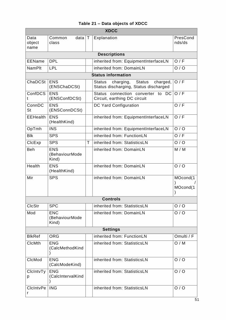
51
Table 21 – Data objects of XDCC
XDCC
Data object name
Common data class
T Explanation PresCond nds/ds
Descriptions
EEName DPL inherited from: EquipmentInterfaceLN O / F
NamPlt LPL inherited from: DomainLN O / O
Status information
ChaDCSt ENS (ENSChaDCSt)
Status charging, Status charged, Status discharging, Status discharged
O / F
ConfDCSt
ENS (ENSConfDCSt)
Status connection converter to DC Circuit, earthing DC circuit
O / F
ConnDCSt
ENS (ENSConnDCSt)
DC Yard Configuration O / F
EEHealth ENS (HealthKind)
inherited from: EquipmentInterfaceLN O / F
OpTmh INS inherited from: EquipmentInterfaceLN O / O
Blk SPS inherited from: FunctionLN O / F
ClcExp SPS T inherited from: StatisticsLN O / O
Beh ENS (BehaviourModeKind)
inherited from: DomainLN M / M
Health ENS (HealthKind)
inherited from: DomainLN O / O
Mir SPS inherited from: DomainLN MOcond(1) / MOcond(1)
Controls
ClcStr SPC inherited from: StatisticsLN O / O
Mod ENC (BehaviourModeKind)
inherited from: DomainLN O / O
Settings
BlkRef ORG inherited from: FunctionLN Omulti / F
ClcMth ENG (CalcMethodKind)
inherited from: StatisticsLN O / M
ClcMod ENG (CalcModeKind)
inherited from: StatisticsLN O / O
ClcIntvTyp
ENG (CalcIntervalKind)
inherited from: StatisticsLN O / O
ClcIntvPer
ING inherited from: StatisticsLN O / O

52
XDCC
Data object name
Common data class
T Explanation PresCond nds/ds
NumSubIntv
ING inherited from: StatisticsLN O / O
ClcRfTyp ENG (CalcIntervalKind)
inherited from: StatisticsLN O / O
ClcRfPer ING inherited from: StatisticsLN O / O
ClcSrc ORG inherited from: StatisticsLN F / M
ClcNxtTmms
ING inherited from: StatisticsLN O / O
InSyn ORG inherited from: StatisticsLN O / O
InRef ORG inherited from: DomainLN Omulti / Omulti

53
7.3 Used, existing classes
7.3.1 LNGroupK
7.3.1.1 KTNK
Table 22 – Used data objects of KTNK
KTNK
Data object name
Common data class
T Explanation M/O/C
LevPct MV Transformer oil sump level. max O
7.3.2 LNGroupM
7.3.2.1 MFLK
Table 23 – Used data objects of MFLK
MFLK
Data object name
Common data class
T Explanation M/O/C
PPPst DEL
Short-term flicker severity of last complete interval for phase to phase measurements O
PhPst WYE
Short-term flicker severity of last complete interval for phase to ground measurements O
PPPlt DEL
Long-term flicker severity of last complete interval for phase to phase measurements O
PhPlt WYE
Long-term flicker severity of last complete interval for phase to ground measurements O
7.3.2.2 MMDC
Table 24 – Used data objects of MMDC
MMDC
Data object name
Common data class
T Explanation M/O/C
Vol MV Voltage V between poles O
VolPsGnd MV
Voltage V between positive pole and ground O
VolNgGnd MV
Voltage V between negative pole and ground O
7.3.2.3 MMET
Table 25 – Used data objects of MMET
MMET
Data object name
Common data class
T Explanation M/O/C
EnvTmp MV Ambient Temperature O

54
7.3.2.4 MMXU
Table 26 – Used data objects of MMXU
MMXU
Data object name
Common data class
T Explanation M/O/C
TotW MV Active Power P MEW O
TotVAr MV Reactive Power Q MEW O
TotVA MV Apparent Power S MEW O
TotPF MV Power Factor MEW O
Hz MV Frequency MEW O
PhV WYE Voltage V O
A WYE Current I O
7.3.3 LNGroupP
7.3.3.1 PTRC
Table 27 – Used data objects of PTRC
PTRC
Data object name
Common data class
T Explanation M/O/C
Str ACD Protection Start O
Op ACT Protection Trip M
7.3.4 LNGroupS
7.3.4.1 SPTR
Table 28 – Used data objects of SPTR
SPTR
Data object name
Common data class
T Explanation M/O/C
BotTmp MV Oil temperature T MEW O
HPTmpAlm SPS
Transformer winding temp.> Warn. O
7.3.5 LNGroupY
7.3.5.1 YPTR
Table 29 – Used data objects of YPTR
YPTR

55
Data object name
Common data class
T Explanation M/O/C
EEHealth ENS Transformer disturbance O
7.3.6 LNGroupZ
7.3.6.1 ZAXN
Table 30 – Used data objects of ZAXN
ZAXN
Data object name
Common data class
T Explanation M/O/C
EEHealth ENS
Auxiliaries system Info (green), Auxiliaries system Warning (yellow), Auxiliaries system Failure (red) O
7.4 Data semantics
Table 31 shows all attributes defined on classes of LogicalNodes_90_14 package.
Table 31 – Attributes defined on classes of LogicalNodes_90_14 package
Name Type (Used in) Description
Ack SPC (ASEQ) Remote Alarm Reset
Alm SPS (KFAS) Fire Alarm
AlmRefInp SPS (CFPC) Reference value disturbed
Cancel SPC (ASEQ) Abort Sequence
ChaDCSt ENS (ENSChaDCSt)
(XDCC) Status charging, Status charged, Status discharging, Status discharged
ConfDCSt ENS (ENSConfDCSt)
(XDCC) Status connection converter to DC Circuit, earthing DC circuit
ConnDCSt ENS (ENSConnDCSt)
(XDCC) DC Yard Configuration
DCAmpFix APC (CFPC) reference value DC Current Fix
DCAmpRmpRte
APC (CFPC) ramp rate for change of DC Current [A/s]
DCVolFix APC (CFPC) reference value DC Voltage Setpoint
EnaExtDev SPC (CFPC) TRUE: control of external devices by converter is enabled;
FALSE: control of external devices by converter is disabled
EnaOpCmd1
SPS (ASEQ) Operation Command 1 enable
ExtAng MV (MCON) Converter Valve Extinction Angle
FRefA APC (CFPC) reference value FRefA [Hz]
FRefB APC (CFPC) reference value FRefB [Hz]
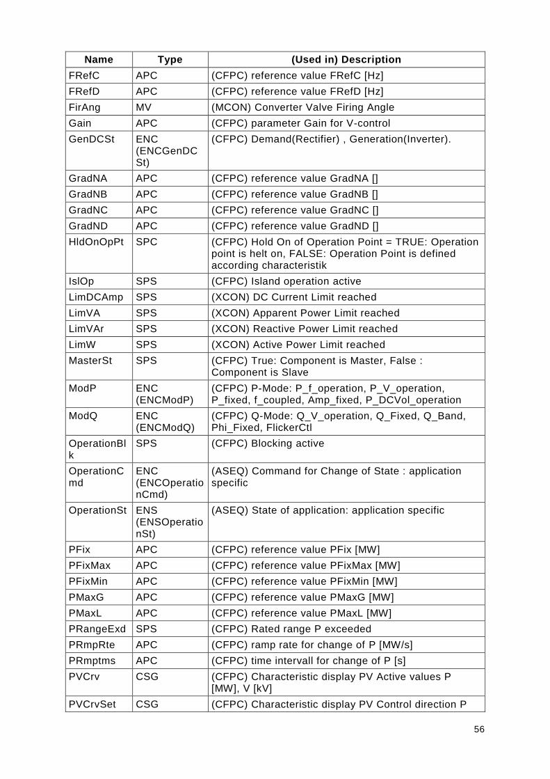
56
Name Type (Used in) Description
FRefC APC (CFPC) reference value FRefC [Hz]
FRefD APC (CFPC) reference value FRefD [Hz]
FirAng MV (MCON) Converter Valve Firing Angle
Gain APC (CFPC) parameter Gain for V-control
GenDCSt ENC (ENCGenDCSt)
(CFPC) Demand(Rectifier) , Generation(Inverter).
GradNA APC (CFPC) reference value GradNA []
GradNB APC (CFPC) reference value GradNB []
GradNC APC (CFPC) reference value GradNC []
GradND APC (CFPC) reference value GradND []
HldOnOpPt SPC (CFPC) Hold On of Operation Point = TRUE: Operation point is helt on, FALSE: Operation Point is defined according characteristik
IslOp SPS (CFPC) Island operation active
LimDCAmp SPS (XCON) DC Current Limit reached
LimVA SPS (XCON) Apparent Power Limit reached
LimVAr SPS (XCON) Reactive Power Limit reached
LimW SPS (XCON) Active Power Limit reached
MasterSt SPS (CFPC) True: Component is Master, False : Component is Slave
ModP ENC (ENCModP)
(CFPC) P-Mode: P_f_operation, P_V_operation, P_fixed, f_coupled, Amp_fixed, P_DCVol_operation
ModQ ENC (ENCModQ)
(CFPC) Q-Mode: Q_V_operation, Q_Fixed, Q_Band, Phi_Fixed, FlickerCtl
OperationBlk
SPS (CFPC) Blocking active
OperationCmd
ENC (ENCOperationCmd)
(ASEQ) Command for Change of State : application specific
OperationSt ENS (ENSOperationSt)
(ASEQ) State of application: application specific
PFix APC (CFPC) reference value PFix [MW]
PFixMax APC (CFPC) reference value PFixMax [MW]
PFixMin APC (CFPC) reference value PFixMin [MW]
PMaxG APC (CFPC) reference value PMaxG [MW]
PMaxL APC (CFPC) reference value PMaxL [MW]
PRangeExd SPS (CFPC) Rated range P exceeded
PRmpRte APC (CFPC) ramp rate for change of P [MW/s]
PRmptms APC (CFPC) time intervall for change of P [s]
PVCrv CSG (CFPC) Characteristic display PV Active values P [MW], V [kV]
PVCrvSet CSG (CFPC) Characteristic display PV Control direction P
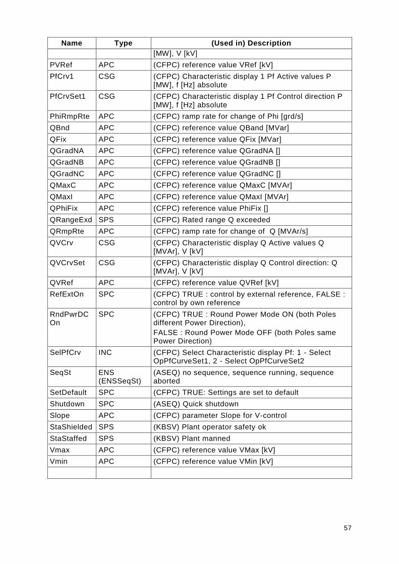
57
Name Type (Used in) Description
[MW], V [kV]
PVRef APC (CFPC) reference value VRef [kV]
PfCrv1 CSG (CFPC) Characteristic display 1 Pf Active values P [MW], f [Hz] absolute
PfCrvSet1 CSG (CFPC) Characteristic display 1 Pf Control direction P [MW], f [Hz] absolute
PhiRmpRte APC (CFPC) ramp rate for change of Phi [grd/s]
QBnd APC (CFPC) reference value QBand [MVar]
QFix APC (CFPC) reference value QFix [MVar]
QGradNA APC (CFPC) reference value QGradNA []
QGradNB APC (CFPC) reference value QGradNB []
QGradNC APC (CFPC) reference value QGradNC []
QMaxC APC (CFPC) reference value QMaxC [MVAr]
QMaxI APC (CFPC) reference value QMaxI [MVAr]
QPhiFix APC (CFPC) reference value PhiFix []
QRangeExd SPS (CFPC) Rated range Q exceeded
QRmpRte APC (CFPC) ramp rate for change of Q [MVAr/s]
QVCrv CSG (CFPC) Characteristic display Q Active values Q [MVAr], V [kV]
QVCrvSet CSG (CFPC) Characteristic display Q Control direction: Q [MVAr], V [kV]
QVRef APC (CFPC) reference value QVRef [kV]
RefExtOn SPC (CFPC) TRUE : control by external reference, FALSE : control by own reference
RndPwrDCOn
SPC (CFPC) TRUE : Round Power Mode ON (both Poles different Power Direction),
FALSE : Round Power Mode OFF (both Poles same Power Direction)
SelPfCrv INC (CFPC) Select Characteristic display Pf: 1 - Select OpPfCurveSet1, 2 - Select OpPfCurveSet2
SeqSt ENS (ENSSeqSt)
(ASEQ) no sequence, sequence running, sequence aborted
SetDefault SPC (CFPC) TRUE: Settings are set to default
Shutdown SPC (ASEQ) Quick shutdown
Slope APC (CFPC) parameter Slope for V-control
StaShielded SPS (KBSV) Plant operator safety ok
StaStaffed SPS (KBSV) Plant manned
Vmax APC (CFPC) reference value VMax [kV]
Vmin APC (CFPC) reference value VMin [kV]

58
8 Description of specific Applications
8.1 SVC
System bus
+
VSC TSC
FACTS
1 Grid Connection
=X1
=TB1.1 =TB1.2
=TB1
LN [ASEQ]
LN [CFPC]
LN [XCON]
=TB1.1
LN [ASEQ]
=TB1.2
LN xxx
LN xxx
LN xxx
Figure 25 – Scheme of SVC application
The SVC application, shown at 025, is used for voltage stabilisation of power transmission and distribution networks. The SVC is parallel connected to the network (=X1), typically using a coupling transformer (=TA1).
In this description are three types of SVCs considered:
Voltage Source Converter (VSC, also called STATCOM type)
classic SVC type which consisting elements like
o thyristor switched capacitor (TSC),

59
o thyristor switched reactor (TSR),
o thyristor controlled reactor (TCR) and
o Filters.
The third type of SVC is the hybrid type. It is a SVC which has branches of VSC type (=TB1.1) and elements of a classic SVC, for example a TSC (=TB1.2), as shown at Figure 26.
For modelling of the IEC61850 communication between SVC and grid control it is not essential if the SVC is a VSC, classic SVC or hybrid type. The signals which have to be foreseen for this communication are mostly the same.
=X1
=TA1
=TB1.1 =TB1.2 =TB1.3 =TB1.n
LN [CFPC]
LN [XCON]
=TB1.1 =TB1.2 =TB1.3 =TB1.n
Static VAR
Compensator
(SVC)
1 Grid Connection
M
M
Legend
Master
=TB1
LN [CFPC]
1 … n units
LN [ASEQ]
LN [ASEQ]
LN [CFPC]
LN [XCON]
LN [ASEQ]
LN [CFPC]
LN [XCON]
LN [ASEQ]
LN [CFPC]
LN [XCON]
LN [ASEQ]
Figure 26 – Scheme of SVC application
The required signals for communication between SVC and grid control are splitted into different control areas/locations. Control signals related to the grid (=X1) or to the transformer (=TA1) are independent of the SVC type and configuration. An example for grid related signals is shown in Table 32.
Table 32 – Example for grid related SVC signals
Name Type (Used in) Description
Gain APC (CFPC) parameter Gain for V-control
ModQ ENC (ENCModQ)
(CFPC) Q-Mode: Q_V_operation, Q_Fixed, Q_Band, Phi_Fixed, FlickerCtl
QBnd APC (CFPC) reference value QBand [MVar]
QFix APC (CFPC) reference value QFix [MVar]
QMaxC APC (CFPC) reference value QMaxC [MVAr]
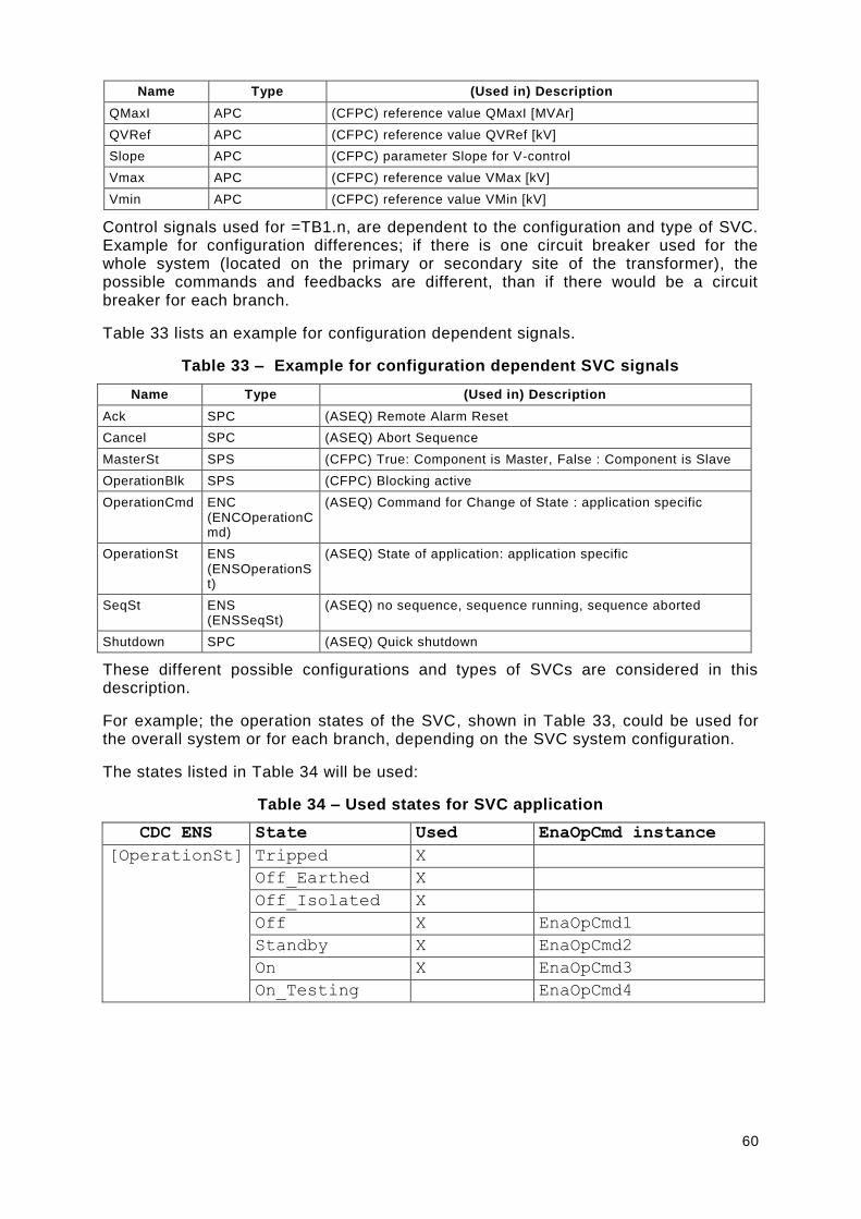
60
Name Type (Used in) Description
QMaxI APC (CFPC) reference value QMaxI [MVAr]
QVRef APC (CFPC) reference value QVRef [kV]
Slope APC (CFPC) parameter Slope for V-control
Vmax APC (CFPC) reference value VMax [kV]
Vmin APC (CFPC) reference value VMin [kV]
Control signals used for =TB1.n, are dependent to the configuration and type of SVC. Example for configuration differences; if there is one circuit breaker used for the whole system (located on the primary or secondary site of the transformer), the possible commands and feedbacks are different, than if there would be a circuit breaker for each branch.
Table 33 lists an example for configuration dependent signals.
Table 33 – Example for configuration dependent SVC signals
Name Type (Used in) Description
Ack SPC (ASEQ) Remote Alarm Reset
Cancel SPC (ASEQ) Abort Sequence
MasterSt SPS (CFPC) True: Component is Master, False : Component is Slave
OperationBlk SPS (CFPC) Blocking active
OperationCmd ENC (ENCOperationCmd)
(ASEQ) Command for Change of State : application specific
OperationSt ENS (ENSOperationSt)
(ASEQ) State of application: application specific
SeqSt ENS (ENSSeqSt)
(ASEQ) no sequence, sequence running, sequence aborted
Shutdown SPC (ASEQ) Quick shutdown
These different possible configurations and types of SVCs are considered in this description.
For example; the operation states of the SVC, shown in Table 33, could be used for the overall system or for each branch, depending on the SVC system configuration.
The states listed in Table 34 will be used:
Table 34 – Used states for SVC application
CDC ENS State Used EnaOpCmd instance
[OperationSt] Tripped X
Off_Earthed X
Off_Isolated X
Off X EnaOpCmd1
Standby X EnaOpCmd2
On X EnaOpCmd3
On_Testing EnaOpCmd4
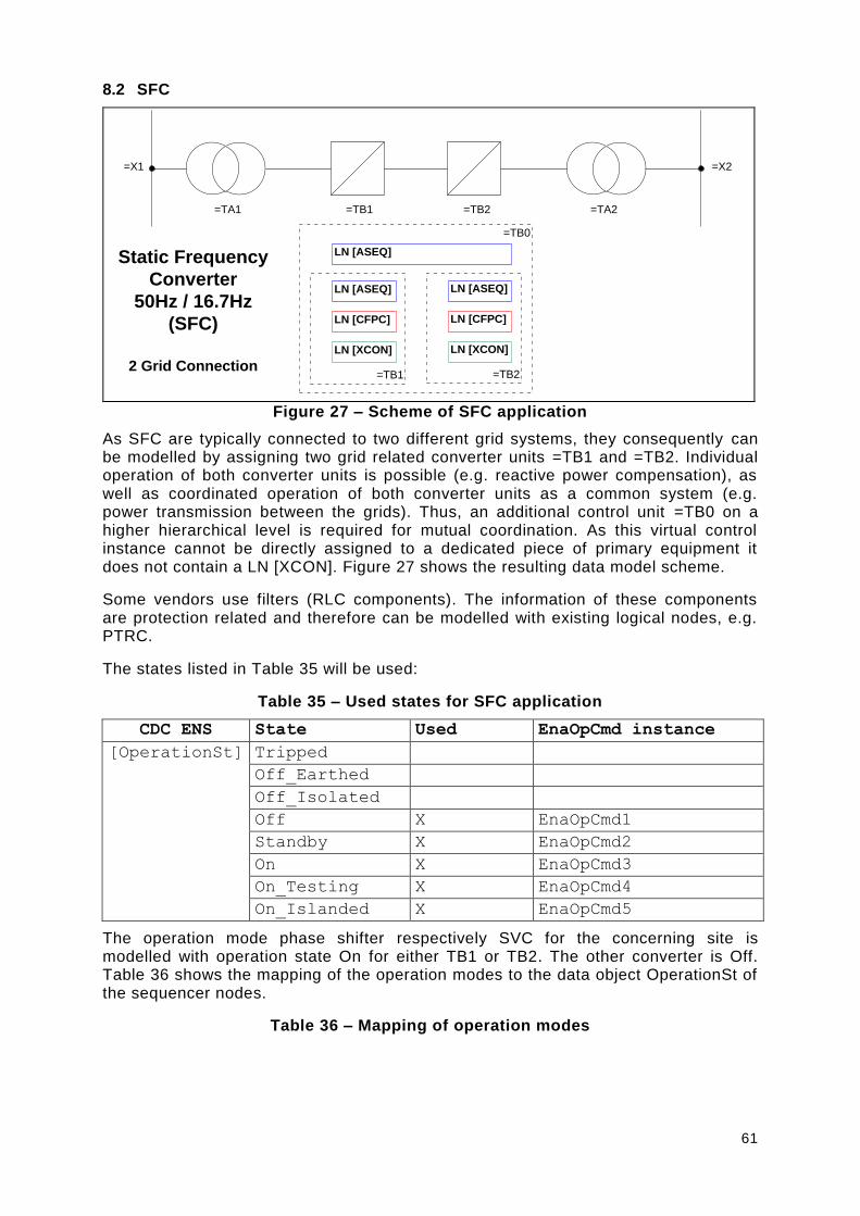
61
8.2 SFC
=TB1 =TB2=TA1 =TA2
=X1 =X2
LN [ASEQ]
LN [CFPC]
LN [XCON]
=TB0
=TB1 =TB2
Static Frequency
Converter
50Hz / 16.7Hz
(SFC)
2 Grid Connection
LN [ASEQ]
LN [CFPC]
LN [XCON]
LN [ASEQ]
Figure 27 – Scheme of SFC application
As SFC are typically connected to two different grid systems, they consequently can be modelled by assigning two grid related converter units =TB1 and =TB2. Individual operation of both converter units is possible (e.g. reactive power compensation), as well as coordinated operation of both converter units as a common system (e.g. power transmission between the grids). Thus, an additional control unit =TB0 on a higher hierarchical level is required for mutual coordination. As this virtual control instance cannot be directly assigned to a dedicated piece of primary equipment it does not contain a LN [XCON]. Figure 27 shows the resulting data model scheme.
Some vendors use filters (RLC components). The information of these components are protection related and therefore can be modelled with existing logical nodes, e.g. PTRC.
The states listed in Table 35 will be used:
Table 35 – Used states for SFC application
CDC ENS State Used EnaOpCmd instance
[OperationSt] Tripped
Off_Earthed
Off_Isolated
Off X EnaOpCmd1
Standby X EnaOpCmd2
On X EnaOpCmd3
On_Testing X EnaOpCmd4
On_Islanded X EnaOpCmd5
The operation mode phase shifter respectively SVC for the concerning site is modelled with operation state On for either TB1 or TB2. The other converter is Off. Table 36 shows the mapping of the operation modes to the data object OperationSt of the sequencer nodes.
Table 36 – Mapping of operation modes

62
State of ASEQx.OperationSt in logical function Description of operation mode
TB0 TB1 TB2
Off Off Off SFC is off
Off On Off SVC for =X1
Off Off On SVC for =X2
Off On On SVC for =X1 and =X2
On On On SFC is on
8.3 HVDC
=TB1.1 =TB2.1=TA1.1 =TA2.1
=X1 =X2
HVDC(Bipole)
LN [CFPC]
LN [XCON]
=TB1.1
M
M Master
=TB1.2 =TB2.2=TA1.2 =TA2.2
LN [CFPC]
=TB1
M
Pole1
Pole2
Station A Station B
LN [XDCC]
LN [ASEQ]
LN [CFPC]
LN [XCON]
=TB1.2
M
LN [ASEQ]
LN [ASEQ]
LN [CFPC]
LN [XCON]
=TB2.1
LN [CFPC]
=TB2
LN [XDCC]
LN [ASEQ]
LN [CFPC]
LN [XCON]
=TB2.2
LN [ASEQ]
LN [ASEQ]
Figure 28 – Scheme of typical HVDC application
A so-called “Bipole” is a typical HVDC line-commutated converter (LCC) application. It consists of two identical converter units per station, which form a “Pole”. They are usually connected to the same AC grid. The same scheme exists at the opposite station. Both stations are connected using an intermediate DC circuit LN [XDCC].
They consequently can be modelled by assigning two grid related transformer units =TA1.1 and =TA1.2 for station A and =TA2.1 and =TA2.2 for station B.

63
The same principle is used for the two grid related converter units =TB1.1 (Station A, Pole 1) and =TB1.2 (Station A, Pole 2) and =TB2.1 (Station B, Pole 1) and =TB2.2 (Station B, Pole 2), all represented by LN [XCON] primary equipment-wise.
Control using LN [CFPC] is achieved by a hierarchical structure: on a Pole level (comprising both stations) and a superordinated Bipole level (also comprising both stations).
Each level usually incorporates its dedicated control systems respectively IEDs (“Bipole Control”, “Pole Control”) in a redundant system configuration. As there may be thousands of kilometres distance between both stations, an identical set of control systems exists at both stations, with an identical functionality. Usually, one system of each station actively controls the power transmission as a “Master”, and the remote station follows as a “Slave”, while always being able to locally establish backup control in case of e.g. telecommunication loss between both stations.
Individual control of both Poles is possible, whilst they usually are operated in combined mode, defined by control points on Bipole level for mutual coordination. As this virtual control instance cannot be directly assigned to a dedicated piece of primary equipment it does not contain a LN [XCON].
The states listed in Table 37 and Table 38 will be used, dependant of the hierarchical modelling level:
Table 37 – Used ASEQ states for HVDC application on Pole level
CDC ENS State Used EnaOpCmd
instance
Typical HVDC
domain
nomenclature
[OperationSt
]
Off_Earthed X EnaOpCmd1 EARTHED
Off_Isolated X EnaOpCmd2 STOPPED
Standby X EnaOpCmd3 STANDBY
Off X EnaOpCmd4 BLOCKED
On X EnaOpCmd5 DEBLOCKED
On_Testing X EnaOpCmd6 OPEN LINE TEST
On_Islanded
Table 38 – Used ASEQ states for HVDC application on Bipole level
CDC ENS State Used EnaOpCmd
instance
Typical HVDC
domain
nomenclature
[OperationSt] Off X EnaOpCmd1 BIPOLAR BLOCKED
On X EnaOpCmd2 BIPOLAR DEBLOCKED
Table 39 shows the needed operation modes.
Table 39 – Mapping of operation modes
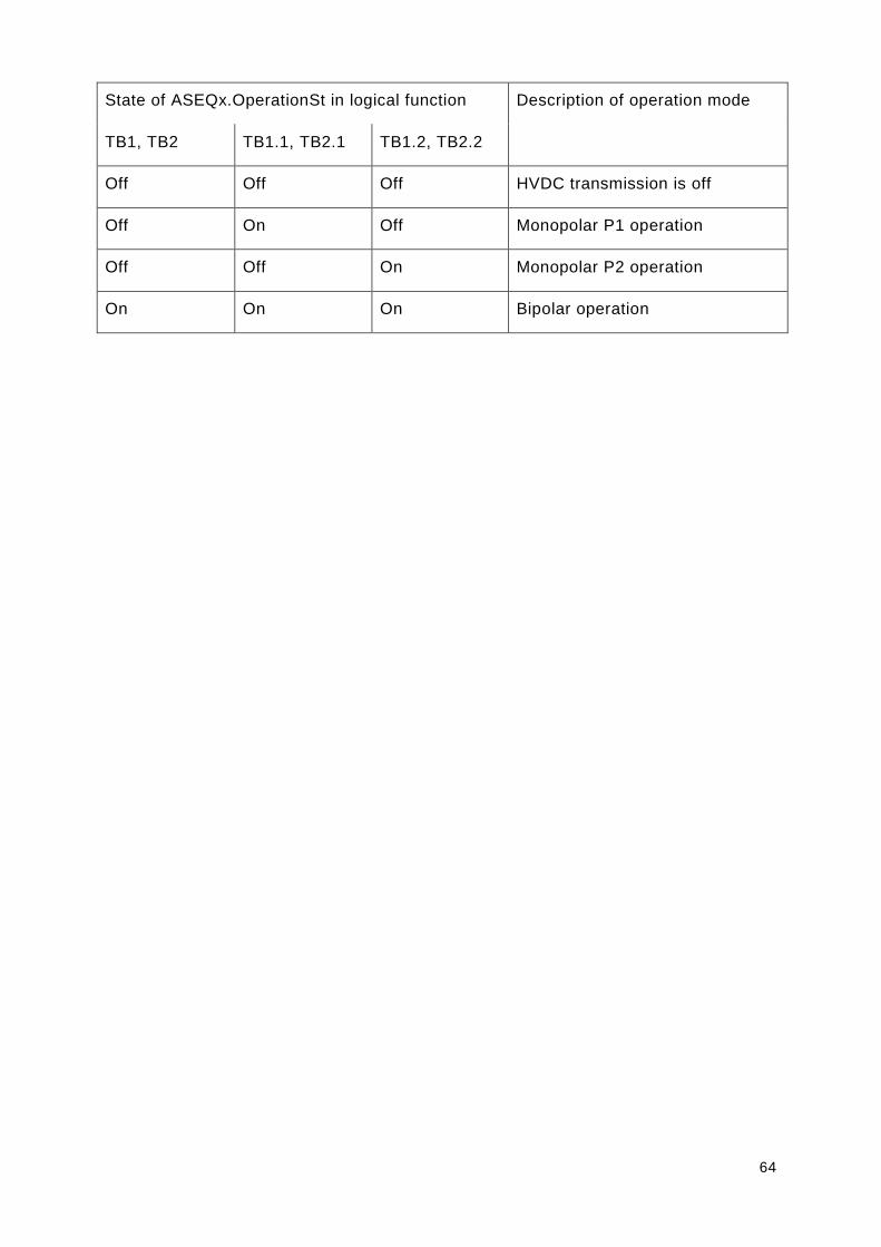
64
State of ASEQx.OperationSt in logical function Description of operation mode
TB1, TB2 TB1.1, TB2.1 TB1.2, TB2.2
Off Off Off HVDC transmission is off
Off On Off Monopolar P1 operation
Off Off On Monopolar P2 operation
On On On Bipolar operation
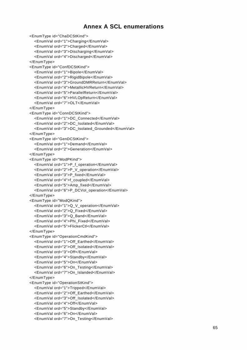
65
Annex A SCL enumerations
<EnumType id="ChaDCStKind">
<EnumVal ord="1">Charging</EnumVal>
<EnumVal ord="2">Charged</EnumVal>
<EnumVal ord="3">Discharging</EnumVal>
<EnumVal ord="4">Discharged</EnumVal>
</EnumType>
<EnumType id="ConfDCStKind">
<EnumVal ord="1">Bipole</EnumVal>
<EnumVal ord="2">RigidBipole</EnumVal>
<EnumVal ord="3">GroundDMRReturn</EnumVal>
<EnumVal ord="4">MetallicHVReturn</EnumVal>
<EnumVal ord="5">ParallelReturn</EnumVal>
<EnumVal ord="6">HVLOpReturn</EnumVal>
<EnumVal ord="7">OLT</EnumVal>
</EnumType>
<EnumType id="ConnDCStKind">
<EnumVal ord="1">DC_Connected</EnumVal>
<EnumVal ord="2">DC_Isolated</EnumVal>
<EnumVal ord="3">DC_Isolated_Grounded</EnumVal>
</EnumType>
<EnumType id="GenDCStKind">
<EnumVal ord="1">Demand</EnumVal>
<EnumVal ord="2">Generation</EnumVal>
</EnumType>
<EnumType id="ModPKind">
<EnumVal ord="1">P_f_operation</EnumVal>
<EnumVal ord="2">P_V_operation</EnumVal>
<EnumVal ord="3">P_fixed</EnumVal>
<EnumVal ord="4">f_coupled</EnumVal>
<EnumVal ord="5">Amp_fixed</EnumVal>
<EnumVal ord="6">P_DCVol_operation</EnumVal>
</EnumType>
<EnumType id="ModQKind">
<EnumVal ord="1">Q_V_operation</EnumVal>
<EnumVal ord="2">Q_Fixed</EnumVal>
<EnumVal ord="3">Q_Band</EnumVal>
<EnumVal ord="4">Phi_Fixed</EnumVal>
<EnumVal ord="5">FlickerCtl</EnumVal>
</EnumType>
<EnumType id="OperationCmdKind">
<EnumVal ord="1">Off_Earthed</EnumVal>
<EnumVal ord="2">Off_Isolated</EnumVal>
<EnumVal ord="3">Off</EnumVal>
<EnumVal ord="4">Standby</EnumVal>
<EnumVal ord="5">On</EnumVal>
<EnumVal ord="6">On_Testing</EnumVal>
<EnumVal ord="7">On_Islanded</EnumVal>
</EnumType>
<EnumType id="OperationStKind">
<EnumVal ord="1">Tripped</EnumVal>
<EnumVal ord="2">Off_Earthed</EnumVal>
<EnumVal ord="3">Off_Isolated</EnumVal>
<EnumVal ord="4">Off</EnumVal>
<EnumVal ord="5">Standby</EnumVal>
<EnumVal ord="6">On</EnumVal>
<EnumVal ord="7">On_Testing</EnumVal>

66
<EnumVal ord="8">On_Islanded</EnumVal>
</EnumType>
<EnumType id="SeqStKind">
<EnumVal ord="1">Sequence_Off</EnumVal>
<EnumVal ord="2">Sequence_On</EnumVal>
<EnumVal ord="3">Sequence_Aborted</EnumVal>
</EnumType>

67
Annex B SCL-Description of different applications
Examplary applications are described with SCL and attached as separated SCD files to this document.

68
Annex C State Machines
[OperationSt]= Off
[SeqSt]= Sequence_Off
[OperationSt] = Off
[SeqSt]= Sequence_On
[OperationCmd]
:= On
[OperationSt]= On
[SeqSt]= Sequence_Off
[SeqSt]
:= Sequence_off
[OperationSt] = Standby
[SeqSt] = Sequence_Off
[OperationCmd]= Off
[SeqSt]= Sequence_On
[OperationCmd]
:= Standby
[SeqSt]
:= Sequence_off
[OperationSt]= On_Islanded
[SeqSt]= Sequence_Off
[OperationSt]= On_Testing
[SeqSt]= Sequence_Off
[OperationCmd]
:= On_Testing
[OperationSt]= Off
[SeqSt]= Sequence_On
[SeqSt]
:= Sequence_off
[OperationSt]= On_Testing
[SeqSt]= Sequence_On
[OperationSt] = On
[SeqSt]= Sequence_On
[OperationCmd] := Off
[SeqSt]
:= Sequence_off
[OperationCmd]
:= Off
[SeqSt]
:= Sequence_off
[OperationSt] = Standby
[SeqSt]= Sequence_On
[OperationCmd]
:= Off
[SeqSt]
:= Sequence_off
[OperationSt] = On
[SeqSt]= Sequence_On
[OperationSt] = On_Islanded
[SeqSt]= Sequence_On
[OperationCmd]
:= On_Islanded
[OperationCmd]
:= On
[OperationSt] = On_Islanded
[SeqSt]= Sequence_On
[SeqSt]
:= Sequence_off
[SeqSt]
:= Sequence_off[OperationCmd]
:= Off
[SeqSt]
:= Sequence_off
[OperationSt] = Standby
[SeqSt]= Sequence_On
[OperationSt] = On
[SeqSt]= Sequence_On
[OperationCmd]
:= Standby
[OperationCmd]
:= On
[SeqSt]
:= Sequence_off
[SeqSt]
:= Sequence_off
[OperationSt]= Off
[SeqSt]= Sequence_On
Transient State
[OperationSt] = Standby
[SeqSt] = Sequence_Off
OperatiOn State
[OperationSt] = Off
[SeqSt]= Sequence_On
[OperationCmd]
:= On_Islanded
[SeqSt]
:= Sequence_off
[OperationSt] = On_Islanded
[SeqSt]= Sequence_On
[OperationSt] = Standby
[SeqSt]= Sequence_On
[OperationCmd]
:= On_Islanded
[SeqSt]
:= Sequence_off
[SeqSt]
:= Sequence_off
[OperationCmd]
:= Standby
[OperationSt]= Off_Earthed
[SeqSt]= Sequence_Off
[OperationSt]= Off_Isolated
[SeqSt]= Sequence_Off
[OperationSt] = Off
[SeqSt]= Sequence_On
[OperationSt] = Off_Isolated
[SeqSt]= Sequence_On
[OperationSt] = Off_Isolated
[SeqSt]= Sequence_On
[OperationSt] = Off_Earthed
[SeqSt]= Sequence_On
[OperationCmd]
:= Off_Isolated
[SeqSt]
:= Sequence_off
[SeqSt]
:= Sequence_off
[OperationCmd]
:= Off
[OperationCmd]
:= Off_Earthed
[OperationCmd]
:= Off_Isolated
[SeqSt]
:= Sequence_off
[SeqSt]
:= Sequence_off
Figure 29 – State machine regular operation

69
[OperationSt]= Off
[SeqSt]= Sequence_Off
[OperationSt] = Off
[SeqSt]= Sequence_On
[OperationSt]
:= On; Standby; On_Islanded; On_Testing
[OperationSt]= Off
[SeqSt]= Sequence_Aborted
[Cancel]
:= TRUE
[OperationSt]= Off
[SeqSt]= Sequence_On
Transient State
[OperationSt] = Hot-Standby
[SeqSt] = Sequence_Off
Operation State
[OperationSt]
:= On; Off; Standby; On_Islanded; On_Testing
[OperationSt]= On
[SeqSt]= Sequence_Off
[OperationSt] = On
[SeqSt]= Sequence_On
[OperationSt]
:= Off; Standby; On_Islanded
[OperationSt]= On
[SeqSt]= Sequence_Aborted
[Cancel]
:= TRUE
[OperationSt]
:= On; Off; Standby; On_Islanded
[OperationSt]= Standby
[SeqSt]= Sequence_Off
[OperationSt] = Standby
[SeqSt]= Sequence_On
[OperationSt]
:= On; Off; On_Islanded
[OperationSt]= Standby
[SeqSt]= Sequence_Aborted
[Cancel]
:= TRUE
[OperationSt]
:= On; Off; Standby; On_Islanded
[OperationSt]= On_Islanded
[SeqSt]= Sequence_Off
[OperationSt] = On_Islanded
[SeqSt]= Sequence_On
[OperationSt]
:= On;Off; Standby
[OperationSt]= On_Islanded
[SeqSt]= Sequence_Aborted
[Cancel]
:= TRUE
[OperationSt]
:= On; Off; Standby; On_Islanded
[OperationSt]= On_Testing
[SeqSt]= Sequence_Off
[OperationSt] = On_Testing
[SeqSt]= Sequence_On
[OperationSt]
:= Off
[OperationSt]= On_Testing
[SeqSt]= Sequence_Aborted
[Cancel]
:= TRUE
[OperationSt]
:= Off; On_Testing
E.g. OperationSt := On Or
OperationSt := Off Or
OperationSt := Standby Or
OperationSt := On_Islanded Or
OperationSt := On_Testing
[OperationSt]= Off
[SeqSt]= Sequence_Off
[OperationSt] = Off
[SeqSt]= Sequence_On
[OperationSt]
:= Off_Isolated
[OperationSt]
= Off[SeqSt]
= Sequence_Aborted
[Cancel]
:= TRUE
[OperationSt]
:= Off; Off_Isolated
[OperationSt]= Off_Isolated
[SeqSt]= Sequence_Off
[OperationSt] = Off_Isolated
[SeqSt]= Sequence_On
[OperationSt]
:= Off; Off_Earthed
[OperationSt]= Off_Isolated
[SeqSt]= Sequence_Aborted
[Cancel]
:= TRUE
[OperationSt]
:= Off; Off_Isolated; Off_Earthed
[OperationSt]= Off_Earthed
[SeqSt]= Sequence_Off
[OperationSt] = Off
[SeqSt]= Sequence_On
[OperationSt]
:= Off_Isolated
[OperationSt]= Off_Earthed
[SeqSt]= Sequence_Aborted
[Cancel]
:= TRUE
[OperationSt]
:= Off_Earthed; Off_Isolated
Figure 30 – State machine for cancel sequence
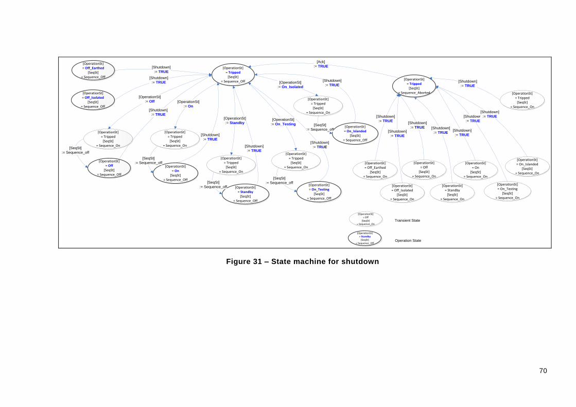
70
[OperationSt]= Off
[SeqSt]= Sequence_Off
[OperationSt] = Off
[SeqSt]= Sequence_On
[OperationSt] = Standby
[SeqSt] = Sequence_Off
[OperationSt]= On_Islanded
[SeqSt]= Sequence_Off
[OperationSt]= On_Testing
[SeqSt]= Sequence_Off
[OperationSt]= On_Testing
[SeqSt]= Sequence_On
[OperationSt] = On
[SeqSt]= Sequence_On
[Shutdown]
:= TRUE
[OperationSt] = Standby
[SeqSt]= Sequence_On
[OperationSt] = On_Islanded
[SeqSt]= Sequence_On
[OperationSt]= Tripped
[SeqSt]= Sequence_Off
[Shutdown]
:= TRUE
[Shutdown]
:= TRUE
[Shutdown]
:= TRUE
[Shutdown]
:= TRUE
[Shutdown]
:= TRUE
[Shutdown]
:= TRUE
[Shutdown]
:= TRUE
[Shutdown]
:= TRUE
[Shutdown]
:= TRUE
[OperationSt]= Tripped
[SeqSt]= Sequence_Aborted
[Ack]
:= TRUE
[OperationSt]= Tripped
[SeqSt]= Sequence_On
[OperationSt]
:= Off
[SeqSt]
:= Sequence_off
[OperationSt]= On
[SeqSt]= Sequence_Off
[OperationSt]= Off
[SeqSt]= Sequence_On
Transient State
[OperationSt] = Standby
[SeqSt] = Sequence_Off
Operation State
[OperationSt]= Tripped
[SeqSt]= Sequence_On
[OperationSt]= Tripped
[SeqSt]= Sequence_On
[OperationSt]= Tripped
[SeqSt]= Sequence_On
[OperationSt]= Tripped
[SeqSt]= Sequence_On
[OperationSt]
:= On_Isolated
[OperationSt]
:= On_Testing
[OperationSt]
:= Standby
[OperationSt]
:= On
[SeqSt]
:= Sequence_off
[SeqSt]
:= Sequence_off[SeqSt]
:= Sequence_off
[SeqSt]
:= Sequence_off
[OperationSt] = Tripped
[SeqSt]= Sequence_On
[Shutdown]
:= TRUE
[OperationSt] = Off_Isolated
[SeqSt]= Sequence_On
[OperationSt] = Off_Earthed
[SeqSt]= Sequence_On
[Shutdown]
:= TRUE
[Shutdown]
:= TRUE
[OperationSt]= Off_Earthed
[SeqSt]= Sequence_Off
[OperationSt]= Off_Isolated
[SeqSt]= Sequence_Off
[Shutdown]
:= TRUE
[Shutdown]
:= TRUE
Figure 31 – State machine for shutdown

71
Annex D Description of Characteristic Curves

72
D.1 Application SFC
D.1.1 Operation Mode: P-f characteristic
Figure 32 – P-f characteristic
Table 40 – Parameters for P-f characteristics
Points P1 to P8 cover the operational range
Characteristic curve is described by array of inflection points P1 … P8
Characteristic curve is described by Reference Values. These are customer specific and can be changed by remote or local SCADA-System
[PMaxL] [PMaxG] [PFixMin] [PFixMax] [PFix] [FRefA] [FRefB] [FRefC] [FRefD] [GradNA] [GradNB]

73
[GradNC] [GradND]
D.1.2 Operation Mode: P fixed
Figure 33 – P fixed characteristic
Table 41 – Parameters for P fixed characteristics
Points P1 to P2 cover the operational range
Characteristic curve is described by array of inflection points P1 P2
Characteristic curve is described by Reference Values. These are customer specific and can be changed by remote or local SCADA-System
[PFix]
D.1.3 Operation Mode: P-V characteristic
Figure 34 – P-V characteristics
Table 42 – Parameters for P-V characteristics

74
Points P1 to P4 cover the operational range
Characteristic curve is described by array of inflection points P1 … P4
Characteristic curve is described by Reference Values. These are customer specific and can be changed by remote or local SCADA-System
[PVRef] [PGradNA] [PMaxL] [PMaxG]
D.1.4 Operation Mode: Q-V characteristic
Figure 35 – Q-V characteristics
Table 43 – Parameters for Q-V characteristics
Points P1 to P4 cover the operational range
Characteristic curve is described by array of inflection points P1 … P4
Characteristic curve is described by Reference Values. These are customer specific and can be changed by remote or local SCADA-System
[QVRef] [QGradNA] [QMaxI] (Inductive) [QMaxC] (Capacitive)

75
D.1.5 Operation Mode: Q fixed
Figure 36 – Q fixed characteristics
Table 44 – Parameters for Q fixed characteristics
Points P1 to P2 cover the operational range
Characteristic curve is described by array of inflection points P1 P2
Characteristic curve is described by Reference Values. These are customer specific and can be changed by remote or local SCADA-System
[QFix]

76
D.1.6 Operation Mode: Phi fixed
Figure 37 – Phi fixed characteristics
Table 45 – Parameters for phi fixed characteristics
Points P1 to P2 cover the operational range
Characteristic curve is described by array of inflection points P1 P2
Characteristic curve is described by Reference Values. These are customer specific and can be changed by remote or local SCADA-System
[QPhiFix] (-180° to +180°)

77
D.2 Application SVC
D.2.1 Operation Mode: Q-V characteristic
Figure 38 – Q-V characteristics
Table 46 – Parameters for Q-V characteristics
Points P1 to P2 cover the operational range
Characteristic curve is described by array of inflection points P1 P2
Characteristic curve is described by Reference Values. These are customer specific and can be changed by remote or local SCADA-System
QVRef] [QGradNA] = Slope/QNom
𝑉𝑎𝑐𝑡 = 𝑉𝑟𝑒𝑓 − 𝑆𝐿𝑂𝑃𝐸 ×𝑄𝑆𝑉𝐶
𝑄𝑁𝑂𝑀
D.2.2 Operation Mode: Q fixed
Table 47 – Q fixed characteristics
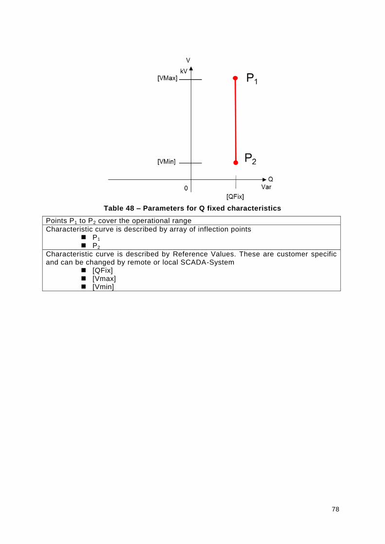
78
Table 48 – Parameters for Q fixed characteristics
Points P1 to P2 cover the operational range
Characteristic curve is described by array of inflection points P1 P2
Characteristic curve is described by Reference Values. These are customer specific and can be changed by remote or local SCADA-System
[QFix] [Vmax] [Vmin]
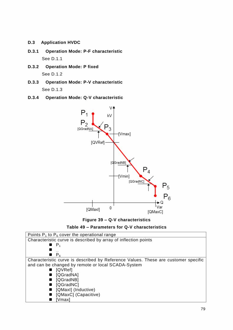
79
D.3 Application HVDC
D.3.1 Operation Mode: P-F characteristic
See D.1.1
D.3.2 Operation Mode: P fixed
See D.1.2
D.3.3 Operation Mode: P-V characteristic
See D.1.3
D.3.4 Operation Mode: Q-V characteristic
Figure 39 – Q-V characteristics
Table 49 – Parameters for Q-V characteristics
Points P1 to P6 cover the operational range
Characteristic curve is described by array of inflection points P1 … P6
Characteristic curve is described by Reference Values. These are customer specific and can be changed by remote or local SCADA-System
[QVRef] [QGradNA] [QGradNB] [QGradNC] [QMaxI] (Inductive) [QMaxC] (Capacitive) [Vmax]

80
[Vmin]
D.3.5 Operation Mode: Q fixed
See D.1.5
D.3.6 Operation Mode: Phi fixed
See D.1.6

81
Annex E Borders/Remarks
For the generic modelling approach the following boundary conditions apply:
Extensive LN to cover lot of applications
Generic modelling approach deviates from individual applications
Novel modelling approach with high complexity
Forces a concrete choice for specific application