IEC 60601-1:2012 (Ed 3.1) MECA Evaluation Package · 2019-04-17 · MECA 60601-1 Ed3.1 Evaluation...
37
MECA 60601-1 Ed3.1 Evaluation Package BETA, Through Cl. 9.2.2.3 (2018-11-24) Page 1 of 65 Medical Equipment Compliance Associates, LLC http://60601-1.com Created by Brian Biersach 2018 IEC 60601-1:2012 (Ed 3.1) MECA Evaluation Package Aligned with the IECEE CB Scheme TRF Rev. k This Evaluation Package is a summary of the IEC 60601-1:2012 standard, other applicable requirements, guidance information, and interpretations, to help evaluate medical electrical equipment to the requirements of the Standard. It is being provided FREE of charge, to help people understand and meet the requirements for medical devices. The Evaluation Package is not intended to replace the standards specified, so a purchased copy should also be used. The IEC 60601-1:2012 standard can be found on the IEC Webstore: https://webstore.iec.ch/publication/2612 CONTENTS CONTENTS ................................................................................................................................................................. 1 FULL EVALUATION PROCESS STEPS ........................................................................................................................... 2 TEST REFERENCE TABLES (Leakage Current, Dielectric, Creepage/Clearance Spacings) .......................................... 3 TEST REFERENCE TABLES (Temperatures)................................................................................................................. 4 Clause 1: SCOPE, OBJECT, AND RELATED STANDARDS ............................................................................................. 5 Clause 2: NORMATIVE REFERENCES (STANDARDS)................................................................................................... 5 Clause 3: TERMINOLOGY AND DEFINITIONS (see standard for all definitions) ........................................................ 5 Clause 4: GENERAL REQUIREMENTS ......................................................................................................................... 5 Clause 5: GENERAL REQUIREMENTS FOR TESTING ME EQUIPMENT ...................................................................... 10 Clause 6: CLASSIFICATION OF ME EQUIPMENT AND ME SYSTEMS ........................................................................ 11 Clause 7: ME EQUIPMENT IDENTIFICATION, MARKING, AND DOCUMENTS .......................................................... 12 Clause 8: PROTECTION AGAINST ELECTRICAL HAZARDS FROM ME EQUIPMENT................................................... 21 Clause 9: PROTECTION AGAINST MECHANICAL HAZARDS OF ME EQUIPMENT AND ME SYSTEMS ....................... 37 Clause 10: PROTECTION AGAINST UNWANTED AND EXCESSIVE RADIATION HAZARDS ........................................ 44 Clause 11: PROTECTION AGAINST EXCESSIVE TEMPERATURES AND OTHER HAZARDS ......................................... 45 Clause 12: ACCURACY OF CONTROLS AND INSTRUMENTS AND PROTECTION AGAINST HAZARDOUS OUTPUT ... 50 Clause 13: HAZARDOUS SITUATIONS AND FAULT CONDITIONS FOR ME EQUIPMENT .......................................... 52 Clause 14: PROGRAMMABLE ELECTRICAL MEDICAL SYSTEMS (PEMS) ................................................................... 54 Clause 15: CONSTRUCTION OF ME EQUIPMENT..................................................................................................... 57 Clause 16: ME SYSTEMS .......................................................................................................................................... 62 Clause 17: ELECTROMAGNETIC COMPATIBILITY OF ME EQUIPMENT AND ME SYSTEMS ...................................... 65 Annex G: PROTECTION AGAINST HAZARDS OF IGNITION OF FLAMMABLE ANESTHETIC MIXTURES ..................... 65 Annex L: INSULATED WINDING WIRES FOR USE WITHOUT INTERLEAVED INSULATION ........................................ 65
Transcript of IEC 60601-1:2012 (Ed 3.1) MECA Evaluation Package · 2019-04-17 · MECA 60601-1 Ed3.1 Evaluation...

MECA 60601-1 Ed3.1 Evaluation Package BETA, Through Cl. 9.2.2.3 (2018-11-24) Page 1 of 65
Medical Equipment Compliance Associates, LLC http://60601-1.com Created by Brian Biersach 2018
IEC 60601-1:2012 (Ed 3.1) MECA Evaluation Package Aligned with the IECEE CB Scheme TRF Rev. k
This Evaluation Package is a summary of the IEC 60601-1:2012 standard, other applicable requirements, guidance information, and interpretations, to help evaluate medical electrical equipment to the requirements of the Standard. It is being provided FREE of charge, to help people understand and meet the requirements for medical devices. The Evaluation Package is not intended to replace the standards specified, so a purchased copy should also be used. The IEC 60601-1:2012 standard can be found on the IEC Webstore: https://webstore.iec.ch/publication/2612 CONTENTS
CONTENTS ................................................................................................................................................................. 1
FULL EVALUATION PROCESS STEPS ........................................................................................................................... 2
TEST REFERENCE TABLES (Leakage Current, Dielectric, Creepage/Clearance Spacings) .......................................... 3
TEST REFERENCE TABLES (Temperatures) ................................................................................................................. 4
Clause 1: SCOPE, OBJECT, AND RELATED STANDARDS ............................................................................................. 5
Clause 2: NORMATIVE REFERENCES (STANDARDS)................................................................................................... 5
Clause 3: TERMINOLOGY AND DEFINITIONS (see standard for all definitions) ........................................................ 5
Clause 4: GENERAL REQUIREMENTS ......................................................................................................................... 5
Clause 5: GENERAL REQUIREMENTS FOR TESTING ME EQUIPMENT ...................................................................... 10
Clause 6: CLASSIFICATION OF ME EQUIPMENT AND ME SYSTEMS ........................................................................ 11
Clause 7: ME EQUIPMENT IDENTIFICATION, MARKING, AND DOCUMENTS .......................................................... 12
Clause 8: PROTECTION AGAINST ELECTRICAL HAZARDS FROM ME EQUIPMENT ................................................... 21
Clause 9: PROTECTION AGAINST MECHANICAL HAZARDS OF ME EQUIPMENT AND ME SYSTEMS ....................... 37
Clause 10: PROTECTION AGAINST UNWANTED AND EXCESSIVE RADIATION HAZARDS ........................................ 44
Clause 11: PROTECTION AGAINST EXCESSIVE TEMPERATURES AND OTHER HAZARDS ......................................... 45
Clause 12: ACCURACY OF CONTROLS AND INSTRUMENTS AND PROTECTION AGAINST HAZARDOUS OUTPUT ... 50
Clause 13: HAZARDOUS SITUATIONS AND FAULT CONDITIONS FOR ME EQUIPMENT .......................................... 52
Clause 14: PROGRAMMABLE ELECTRICAL MEDICAL SYSTEMS (PEMS) ................................................................... 54
Clause 15: CONSTRUCTION OF ME EQUIPMENT..................................................................................................... 57
Clause 16: ME SYSTEMS .......................................................................................................................................... 62
Clause 17: ELECTROMAGNETIC COMPATIBILITY OF ME EQUIPMENT AND ME SYSTEMS ...................................... 65
Annex G: PROTECTION AGAINST HAZARDS OF IGNITION OF FLAMMABLE ANESTHETIC MIXTURES ..................... 65
Annex L: INSULATED WINDING WIRES FOR USE WITHOUT INTERLEAVED INSULATION ........................................ 65

MECA 60601-1 Ed3.1 Evaluation Package BETA, Through Cl. 9.2.2.3 (2018-11-24) Page 2 of 65
Medical Equipment Compliance Associates, LLC http://60601-1.com Created by Brian Biersach 2018
FULL EVALUATION PROCESS STEPS
X: Completed, P: In Progress
1
PRELIMINARY EVALUATION (may be conducted as separate Project)
- Review intended use, accessories, interconnections, classifications
- Review and determine applicable standards and project scope (IEC 60601 or IEC 61010 standards)
- Construction evaluation, per requirements in standard(s)
- Electrical Insulation diagram generated or reviewed/modified
- Critical Components reviewed for requirements
- Create applicable tests list
- User manual, markings requirements reviewed (provide markings/manual guidance document)
- Risk management, software, and usability requirements reviewed (provide RM, software guidance documents)
- * MECA works with Client addresses any initial noncompliances
2
TESTING (after any initial noncompliances addressed)
- Verify production equivalent samples received and operational
- Take photographs of device/system and components for report
- Send one sample out for any subcontracted testing, as applicable
- Testing to base standard (IEC 60601-1)
- Testing to applicable Collateral Standards (IEC 60601-1-XX):
- IEC 60601-1-xx
- Testing to applicable Particular Standards (IEC 60601-2-XX):
- IEC 60601-2-xx
- ISO 80601-2-xx
- Testing applicable National Differences
* MECA works with Client to addresses any testing noncompliances
- * Conduct retesting, as needed
3
DOCUMENTATION REVIEW
- Review Risk Management process documentation (from completed ISO 14971 RM guidance document)
- Review device Risk Management file documentation (from completed IEC 60601-1 RM guidance document)
- Review user manual and device markings for requirements
- Review software documentation, if applicable (from completed Clause 14 & IEC 62304 guidance documents)
- Review usability documentation, if applicable (from completed IEC 62366 Usability guidance document)
* MECA works with Client to addresses any documentation and markings noncompliances
- * Re-review documentation, as needed
4
REPORT WRITING (International IECEE CB Scheme TRF (Test Report Form) format used)
- Complete clause verdicts and remarks
- Complete risk management references and Clause 4.2.2 table (form reviewed RM guidance document)
- Complete test data tables (from completed internal test data documentation)
- Complete critical components table (with assistance from client, for manufacturer, model, specifications)
- Complete applicable National Deviations report
- Complete Collateral Standards report(s), as applicable:
- IEC 60601-1-xx
- Complete Particular Standards report(s), as applicable:
- IEC 60601-2-xx
- ISO 80601-2-xx
- Complete Additional Standards report(s), as applicable (Software IEC 62304)
- Attach insulation diagram, markings, photos, manual, applicable drawings, and applicable schematics
- Report reviewed internally, addresses any review comments
- Final Report (and Certificate, as applicable) sent to client
5
US & CANADA NRTL SAFETY MARK
- Agency project opened (UL, TUV Rheinland, Intertek-ETL)
- For NRTL Mark, Report submitted to Agency for review and processing
- For NRTL Mark, Agency sends client authorization to apply their safety mark
- For CB Report, Report submitted to UL CB group for review & processing
- For CB Report, UL CB Group sends client CB Certificate (MECA provides CB Report)

MECA 60601-1 Ed3.1 Evaluation Package BETA, Through Cl. 9.2.2.3 (2018-11-24) Page 3 of 65
Medical Equipment Compliance Associates, LLC http://60601-1.com Created by Brian Biersach 2018
TEST REFERENCE TABLES (Leakage Current, Dielectric, Creepage/Clearance Spacings)
TABLE 3 + 4 + Clause 8.7.3: LEAKAGE AND PATIENT AUXILIARY CURRENT LIMITS (in mA, µA, with Fig. 12 MD 1kΩ test circuit) (all AC values rms)
Type of Leakage/Auxiliary Current Type B Limits Type BF Limits Type CF Limits
NC SFC NC SFC NC SFC
Earth (Class I, no accessible earthed parts) 5 mA 10 mA 5 mA 10 mA 5 mA 10 mA
Earth (Class I with accessible earthed parts) 3 500 µA 3 10 mA 500 µA 10 mA 500 µA 10 mA
Touch (Accessible) 100 µA 500 µA 100 µA 500 µA 100 µA 500 µA
Patient (AC) 100 µA 500 µA 100 µA 500 µA 10 µA 50 µA
Patient (DC) 10 µA 50 µA 10 µA 50 µA 10 µA 50 µA
Patient Auxiliary, between parts (AC) 1, 2 100 µA 500 µA 100 µA 500 µA 10 µA 50 µA
Patient Auxiliary, between parts (DC) 1, 2 10 µA 50 µA 10 µA 50 µA 10 µA 50 µA
Total Patient (AC) (all Applied Parts of same Type) 1, 2 500 µA 1,000 µA 500 µA 1,000 µA 50 µA 100 µA
Total Patient (DC) (all Applied Parts of same Type) 1, 2 50 µA 100 µA 50 µA 100 µA 50 µA 100 µA
Patient (Mains on F-Type Applied Part fault) - - - 5 mA - 50 µA
Total Patient (Mains on all F-Type Applied Parts fault) - - - 5 mA - 100 µA
No leakage current exceeds 10mA when tested with non-frequency-weighted 1kΩ test circuit 1 Voltage on SIP/SOPs (communication connections) have same limits specified for NC & SFC. 2 Voltage on non-PE accessible metal parts have limits specified for SFC. 3 Based on accessible earthed parts in SFC of open Ground
TABLE 6: MOPP, MOOP DIELECTRIC WITHSTAND TEST VOLTAGES (Tested in Vrms)
Reference Voltage (U) 1 MOPP Mains
2 MOPP Mains
1 MOPP Secondary
2 MOPP Secondary
1 MOOP Mains
2 MOOP Mains
1 MOOP Secondary
2 MOOP Secondary
< 42.4 Vpk, < 60 Vdc (< 30 Vrms)
1,500 3,000 500
(707 Vdc) 1,000
(1,414 Vdc) 1,000 2,000 None None
< 71 Vpk, < 184 Vdc (< 50 Vrms)
1,500 3,000 750 1,500 1,000 2,000 Table 7 Table 7
< 184 Vpk/Vdc (< 130 Vrms)
1,500 (2,121 Vdc)
3,000 (4,242 Vdc)
1,000 2,000 1,000
(1,414 Vdc) 2,000
(2,828 Vdc) Table 7 Table 7
< 212 Vpk/Vdc (< 150 Vrms)
1,500 3,000 1,000 2,000 1,500 3,000 Table 7 Table 7
< 354 Vpk/Vdc (< 250 Vrms)
1,500 (2,121 Vdc)
4,000 (5,656 Vdc)
1,500 3,000 1,500
(2,121 Vdc) 3,000
(4,242 Vdc) Table 7 Table 7
< 848 Vpk/Vdc (< 600 Vrms)
√2U + 1,000 2 x (√2U + 1,500) √2U + 1,000 2 x (√2U + 1,500) Table 7 3,000 Table 7 Table 7
< 1,414 Vpk/Vdc (< 1,000 Vrms)
√2U + 1,000 2 x (√2U + 1,500) √2U + 1,000 2 x (√2U + 1,500) Table 7 3,000 Table 7 Table 7
< 10,000 Vpk/Vdc (< 7,072 Vrms)
U/√2 + 2,000 2 x (√2U + 5,000) U/√2 + 2,000 2 x (√2U + 5,000) Table 7 Table 7 Table 7 Table 7
< 14,140 Vpk/Vdc (< 10,000 Vrms)
U/√2 + 2,000 2 x (√2U + 5,000) U/√2 + 2,000 2 x (√2U + 5,000) 1.06 x U/√2 1.06 x U/√2 1.06 x U/√2 1.06 x U/√2
If tested at DC, test voltage multiplied by (√2 = 1.414); values provided above for highlighted common values. The rms voltages are provided for the special case where the voltage has a sinusoidal waveform.
TABLE 12: MOPP CREEPAGE, CLEARANCE SPACINGS
Reference Voltage (DC)
Reference Voltage (AC rms)
1 MOPP Creepage
(mm)
1 MOPP Clearance
(mm)
2 MOPP Creepage
(mm)
2 MOPP Clearance
(mm)
≤ 17 ≤ 12 1.7 0.8 3.4 1.6
≤ 43 ≤ 30 2.0 1.0 4.0 2.0
≤ 85 ≤ 60 2.3 1.2 4.6 2.4
≤ 177 ≤ 125 3.0 1.6 6.0 3.2
≤ 354 ≤ 250 4.0 2.5 8.0 5.0
≤ 566 ≤ 400 6.0 3.5 12.0 7.0
≤ 707 ≤ 500 8.0 4.5 16.0 9.0
≤ 934 ≤ 660 10.5 6.0 21.0 12.0
≤ 1,061 ≤ 750 12.0 6.5 24.0 13.0
≤ 1,414 ≤ 1,000 16.0 9.0 32.0 18.0
≤ 1,768 ≤ 1,250 20.0 11.4 40.0 22.8
≤ 2,263 ≤ 1,600 25.0 14.3 50.0 28.6
≤ 2,828 ≤ 2,000 32.0 18.3 64.0 36.6
≤ 3,535 ≤ 2,500 40.0 22.9 80.0 45.8
≤ 4,525 ≤ 3,200 50.0 28.6 100.0 57.2
≤ 5,656 ≤ 4,000 63.0 36.0 126.0 72.0
≤ 7,070 ≤ 5,000 80.0 45.7 160.0 91.4
≤ 8,909 ≤ 6,300 100.0 57.1 200.0 114.2
≤ 11,312 ≤ 8,000 125.0 71.4 250.0 142.8
≤ 14,140 ≤ 10,000 160.0 91.4 320.0 182.8
TABLE 16: 1 MOOP CREEPAGE SPACINGS
Reference Voltage (DC & AC rms)
Pollution Degree 3 (CTI IIIa/b) (mm)
Pollution Degree 2 (CTI IIIa/b) (mm)
Pollution Degree 1 (CTI all) (mm)
≤ 25 1.3 0.5
Use O
nly
Air
Cle
ara
nce
≤ 50 1.9 1.2
≤ 100 2.2 1.4
≤ 125 2.4 1.5
≤ 150 2.5 1.6
≤ 200 3.2 2.0
≤ 250 4.0 2.5
≤ 300 5.0 3.2
≤ 400 6.3 4.0
≤ 600 10.0 6.3
≤ 800 12.5 8.0
≤ 1,000 16.0 10.0
Clearance values used for Creepage if greater than above spacings
TABLE 8: ALTITUDE CLEARANCE MULTIPLIER
Rated Operating Altitude Atmospheric Pressure MOPP Multiplier MOOP Multiplier
≤ 2,000 m (6,562 ft) ≥ 80 kPa (800 mb) (600 mmHg) 1 1 ≤ 3,000 m (9,843 ft) ≥ 70 kPa (700 mb) (525 mmHg) 1 1.14 ≤ 4,000 m (13,123 ft) ≥ 62 kPa (620 mb) (465 mmHg) 1.14 1.29 ≤ 5,000 m (16,404 ft) ≥ 54 kPa (540 mb) (405 mmHg) 1.29 1.48
TABLE 13: 1 MOOP CLEARANCE SPACINGS
Reference Voltage (DC, Peak)
Reference Voltage (AC rms)
Mains ≤ 150V rms Pollution Degree 1, 2
Mains ≤ 300V rms Pollution Degree 1, 2, 3
1 MOOP 2 MOOP 1 MOOP 2 MOOP
≤ 210 ≤ 150 1.0 2.0 2.0 4.0
≤ 420 ≤ 300 2.0 4.0 2.0 4.0
≤ 840 ≤ 600 3.2 6.4 3.2 6.4
≤1,400 ≤ 1,000 4.2 6.4 4.2 6.4
≤ 2,800 ≤ 2,000 8.4
≤ 7,000 ≤ 5,000 17.5
≤9,800 ≤ 7,000 25.0
≤ 14,000 ≤ 10,000 37.0
≤ 28,000 ≤ 20,000 80.0
Mains voltages >300V require additional spacings of Table 14
TABLE 15: MOOP CLEARANCE SPACINGS (Internally Powered, Earthed Secondary Only)
Reference Voltage (DC, Peak)
Reference Voltage (AC rms)
Mains ≤ 150V rms Pollution Degree 1, 2
Mains ≤ 300V rms Pollution Degree 1, 2
1 MOOP 2 MOOP 1 MOOP 2 MOOP
≤ 71 ≤ 50 0.7 1.4 1.0 2.0
≤ 140 ≤ 100 0.7 1.4 1.0 2.0
≤ 210 ≤ 150 0.9 1.8 1.0 2.0
≤ 280 ≤ 200 1.4 2.8 1.4 2.8
≤ 420 ≤ 300 1.9 3.8 1.9 3.8
≤ 700 ≤ 500 2.5 5.0 2.5 5.0
≤ 840 ≤ 600 3.2 5.0 3.2 5.0
≤ 1,400 ≤ 1,000 4.2 5.0 4.2 5.0
≤ 2,800 ≤ 2,000 8.4
≤ 7,000 ≤ 5,000 17.5
≤ 9,800 ≤ 7,000 25.0
≤ 14,000 ≤ 10,000 37.0
≤ 28,000 ≤ 20,000 80.0
≤ 42,000 ≤ 30,000 130.0
Pollution Degree 2: Non-conductive pollution (occasional conductivity from condensation) Material Group CTI IIIb assumed without material tested: 100≤CTI<175
Overvoltage Category = 2: Mains Transient (120V=1,500Vpk), (240V=2,500Vpk) Secondary Overvoltage Category = 1 (rms voltages applicable to sinusoidal waveforms only)

MECA 60601-1 Ed3.1 Evaluation Package BETA, Through Cl. 9.2.2.3 (2018-11-24) Page 4 of 65
Medical Equipment Compliance Associates, LLC http://60601-1.com Created by Brian Biersach 2018
TEST REFERENCE TABLES (Temperatures)
TABLE 22: ALLOWABLE MAXIMUM TEMPERATURES OF PARTS
Parts Limit (°C) Parts Limit (°C)
Class A Windings 105* Parts marked with max. Temp (T) T
Class B Windings 120* Parts contacting flammable liquid flash-point T °C T-25
Class E Windings 130* Wood 90
Class F Windings 155* Other components and materials (max. rating T) T
Class H Windings 180*
*Measurements made outside of windings, subtract 10°C from windings limits
Add: Table 22, 23, SFC Limits, Transformer Windings (short, overload), Motor Windings (locked)

MECA 60601-1 Ed3.1 Evaluation Package BETA, Through Cl. 9.2.2.3 (2018-11-24) Page 5 of 65
Medical Equipment Compliance Associates, LLC http://60601-1.com Created by Brian Biersach 2018
Verdict: P=Pass, N=Not Applicable, F=Fail, N/E=Not Evaluated Clause: IEC 60601-1 Clause reference, (US)=US Differences) Type: Verify, Document, Info, Rationale, Interpretation, TEST/(Test) modification Comment: Information that is required to be documented in TRF, as applicable Requirement: Summary of the clause requirement from the standards
Black: Requirement, Information Gray: Rationale, Interpretation Blue: TEST or (Test) Modification Green: Risk Management Requirement Red: National Difference
Verdict Clause Type Comment Requirement
Clause 1: SCOPE, OBJECT, AND RELATED STANDARDS 1.1 Info Scope:
The basic safety and essential performance of medical electrical equipment and medical electrical systems, hereafter referred to as ME Equipment and ME Systems. Can be applied to equipment for compensation/alleviation of disease, injury, and disability.
Clause 2: NORMATIVE REFERENCES (STANDARDS)
Clause 3: TERMINOLOGY AND DEFINITIONS (see standard for all definitions) 3.27 Info Essential Performance:
Performance of a clinical function, other than that related to basic safety, where loss or degradation beyond the limits specified by the manufacturer results in an unacceptable risk.
3.63 Info Medical Electrical Equipment: Electrical equipment having an applied part or transferring energy to or from the patient or detecting such energy transfer to or from the patient and which is: a) Provided with not more than one connection to a particular supply mains; and b) Intended by its manufacturer to be used: 1) in the diagnosis, treatment, or monitoring of a patient; or 2) for compensation or alleviation of disease, injury or disability (Includes accessories as defined as necessary to enable the normal use of equipment)
3.64 Info Medical Electrical System: Connections, electrical or otherwise, including those intended to transfer signals, data, power, or substances
3.33 Info Functional Connection: Combination, as specified by its manufacturer, of items of equipment, at least one of which is me equipment to be inter-connected by functional connection or by use of a multiple socket-outlet
Clause 4: GENERAL REQUIREMENTS 4.1 - - Conditions for Application to MEE or MES
4.1 Verify Requirements specified in this standard applied in normal use and reasonably foreseeable misuse
4.1 Info - Term patient considered as the person for whom the ME Equipment or ME System is intended.
4.2 - - Risk Management process for MEE & MES
4.2.2 Verify TRF Table 4.2.2 Requirements below
Risk Management Process complies with ISO 14971 (2007) (Only ISO 14971 items required for IEC 60601-1 compliance identified as requirements below)
- - - ISO 14971, Cl. 3: General Requirements of Risk Management
4.2.2 ISO 14971, Cl. 3.1 RM Document(s): Location(s):
Risk Management Process (IEC 60601-1 excludes production and post-production) The following items shall be documented in the risk management file: That an ongoing process shall be established, documented and maintained for: - Identifying hazards - Estimating, evaluating and controlling the risks - Monitoring the effectiveness of risk controls The process shall include these elements: - Risk analysis - Risk evaluation - Risk control That if a documented product realization process exists, it shall: - Incorporate the appropriate parts of the risk management process
4.2.2 ISO 14971, Cl. 3.2 RM Document(s): Location(s):
Management Responsibilities The following items shall be documented in the risk management file: Evidence that top management is committed to providing adequate Resources
4.2.2 ISO 14971, Cl. 3.2 RM Document(s): Location(s):
Management Responsibilities The following items shall be documented in the risk management file: Evidence that top management is committed to the assignment of Qualified Personnel
4.2.2 ISO 14971, Cl. 3.2 RM Document(s): Location(s):
Management Responsibilities The following items shall be documented in the risk management file: That a policy shall be designed and documented for: - Determining Criteria for Risk Acceptability That management policy ensures criteria based on: - National/regional regulations and international standards - Takes into account known stakeholder concerns and accepted state of the art

MECA 60601-1 Ed3.1 Evaluation Package BETA, Through Cl. 9.2.2.3 (2018-11-24) Page 6 of 65
Medical Equipment Compliance Associates, LLC http://60601-1.com Created by Brian Biersach 2018
Verdict Clause Type Comment Requirement
4.2.2 ISO 14971, Cl. 3.3 RM Document(s): Location(s):
Qualification of Personnel Specify that the following items shall be documented in the risk management file: Risk management tasks are completed by persons having: - The knowledge and experience appropriate to the tasks they are assigned, including * Device experience * Technical experience * Risk management techniques, as appropriate - Qualification records are maintained
4.2.2 ISO 14971, Cl. 3.4 RM Document(s): Location(s):
Risk Management Plan The following items shall be documented in the risk management file: That risk management activities shall: - Be planned - Include changes to the plan made over the life-cycle of the device That plans shall be prepared for particular medical devices/accessories, and shall include at a minimum:
4.2.2 ISO 14971, Cl. 3.4a RM Document(s): Location(s):
Scope The following items shall be documented in the risk management file: Scope of the planned activities identifying the medical device, including: - Description of the device - Life-cycle phases covered by the plan
4.2.2 ISO 14971, Cl. 3.4b RM Document(s): Location(s):
Assignment of Responsibilities and Authorities The following items shall be documented in the risk management file: Specification of the assignment of responsibilities and authorities
4.2.2 ISO 14971, Cl. 3.4c RM Document(s): Location(s):
Review Requirements for Risk Management Activities The following items shall be documented in the risk management file: Specification of the review requirements for risk management activities
4.2.2 ISO 14971, Cl. 3.4d RM Document(s): Location(s):
Criteria for Risk Acceptability The following items shall be documented in the risk management file: Criteria based on the manufacturers policy Criteria for accepting risks when the probability cannot be estimated
4.2.2 ISO 14971, Cl. 3.4e RM Document(s): Location(s):
Verification Activities The following items shall be documented in the risk management file: Specification of the verification activities
- ISO 14971, Cl. 3.4f Not required for IEC 60601-1
Production and Post-Production Collection & review of production and post-production information
4.2.2 ISO 14971, Cl. 3.5 RM Document(s): Location(s):
Risk Management File The following items shall be documented in the risk management file: That a risk management file shall be established for each device That the risk management file shall provide traceability for each hazard to: - Risk analysis - Risk evaluation - Implementation and verification of mitigations (control measures) - Assessment of residual risk acceptability
4.2.2 ISO 14971, Cl. 4.1 RM Document(s): Location(s):
Risk analysis process The following items shall be documented in the risk management file: That a risk analysis shall be performed That implementation of the planned activities and result of the risk analysis shall be documented That the risk analysis shall include at a minimum: a) Description & identification of the items covered b) Identification of personnel performing the risk analysis c) Scope and date of the risk analysis
4.2.2 ISO 14971, Cl. 4.2 RM Document(s): Location(s):
Product Specifications (Intended Use and Characteristics Related to the Safety) The following items shall be documented in the risk management file: - Intended use and reasonably foreseeable misuse identified - Listing of characteristics (qualitative and quantitative) that could impact the safety of the medical device - Any appropriate limits
4.2.2 ISO 14971, Cl. 4.3 RM Document(s): Location(s):
Identification of Hazards The following items shall be documented in the risk management file: - List compiled of known and foreseeable hazards for the device in normal and fault conditions
4.2.2 ISO 14971, Cl. 4.4 RM Document(s): Location(s):
Estimation of the Risk(s) For Each Hazardous Situation The following items shall be documented in the risk management file: -Reasonably foreseeable sequences/combinations of events leading to hazardous situations considered - The hazardous situation is recorded - Risk(s) for each hazardous situation shall be estimated using available data or information - Where the probability of occurrence cannot be estimated, the resulting consequences shall be identified for use in the risk evaluation/control - Activities are recorded in the risk management file - Any systems used for qualitative/quantitative categorization of probability/severity shall be documented in the risk management file

MECA 60601-1 Ed3.1 Evaluation Package BETA, Through Cl. 9.2.2.3 (2018-11-24) Page 7 of 65
Medical Equipment Compliance Associates, LLC http://60601-1.com Created by Brian Biersach 2018
Verdict Clause Type Comment Requirement
4.2.2 ISO 14971, Cl. 5 RM Document(s): Location(s):
Risk Evaluation The following items shall be documented in the risk management file: - All identified hazardous situation shall be evaluated to determine if risk reduction is required, based on the criteria defined in the plan - The results of the evaluation are recorded in the risk management file
- ISO 14971, Cl. 6.1 Not required by IEC 60601-1 Ed.3.1
Risk Reduction - Where reduction is required, risk control activities are performed
4.2.2 ISO 14971, Cl. 6.2 RM Document(s): Location(s):
Risk Control Option Analysis The following items shall be documented in the risk management file: That risk control measures appropriate for reducing risks to an acceptable level shall be identified That one or more risk control measures shall be applied in the following priority: a) Safety by design (inherent) - elimination of the hazard or hazardous situation b) Protective measures in the device or manufacturing process - Prevent the hazard or hazardous situation from occurring c) Information for safety - Provide warnings related to the hazard or hazardous situation That the selected, risk control measure shall be documented in the risk management file That where further risk reduction is impractical, a risk/benefit analysis of the residual shall be performed
4.2.2 ISO 14971, Cl. 6.3 RM Document(s): Location(s):
Implementation of Risk Control Measure(s) Specify that the following items shall be documented in the risk management file: That selected risk control measures shall be implemented That the implementation and its effectiveness shall be verified and documented in the risk management file
4.2.2 ISO 14971, Cl. 6.4 RM Document(s): Location(s):
Residual Risk Evaluation Specify that the following items shall be documented in the risk management file: That risk remaining after the implementation of the risk control shall be evaluated against the criteria in the risk management plan That further risk control shall be applied where the residual risk is not judged acceptable That for acceptable residual risk, the manufacturer shall determine which residual risks to disclose (including what information is necessary) NOTE: this is looking at each risk individually
4.2.2 ISO 14971, Cl. 6.5 RM Document(s): Location(s):
Risk/Benefit Analysis Specify that the following items shall be documented in the risk management file: That for residual risk not meeting the criteria for risk acceptability where further risk control is impractical, the manufacturer may gather data/literature to determine if benefit of the device outweighs the residual risk (If not, the risk remains unacceptable) That where the benefit outweighs the residual risk, the manufacturer shall identify any information for safety required to disclose the residual risk That this review shall be documented in the risk management file That this assessment is performed on individual risks
4.2.2 ISO 14971, Cl. 6.6 See below for Document, Location
Risks arising from risk control measures That the impact of risk controls shall be reviewed with regard to:
4.2.2 ISO 14971, Cl. 6.6a RM Document(s): Location(s):
Introducing New Hazards/Hazardous Situations Specify that the following items shall be documented in the risk management file: That the impact on risk controls are reviewed for introducing new hazardous situations That any new/increased risks are subjected to the requirements of this standard and documented in the risk management file
4.2.2 ISO 14971, Cl. 6.6b RM Document(s): Location(s):
Affect on the Estimated Risks for Previously Identified Hazardous Situations Specify that the following items shall be documented in the risk management file: That the impact on risk controls are reviewed for the effect on the estimated risks for previously identified hazardous situations That any new/increased risks are subjected to the requirements of this standard and documented in the risk management file
4.2.2 ISO 14971, Cl. 6.7 RM Document(s): Location(s):
Completeness of Risk Control Specify that the following items shall be documented in the risk management file: That an assessment shall be performed to ensure that risks from all identified hazardous situations have been considered That this assessment shall be documented in the risk management file
4.2.2 ISO 14971, Cl. 7 RM Document(s): Location(s):
Overall Residual Risk Acceptability Specify that the following items shall be documented in the risk management file: That following implementation & verification of all risk control measures: - Manufacturer shall determine if the overall residual risk of the device is acceptable, based on the criteria defined in the risk management plan NOTE: this is looking at the overall risk profile, not each risk individually Where the overall residual risk is judged to be unacceptable: - Manufacturer may gather data & literature on the medical benefit of the device (intended use / purpose) to determine if they outweigh the overall residual risk - If not, the residual risk remains unacceptable - Where acceptable, the manufacturer shall determine what information is necessary to include in the accompanying documents to disclose residual risk That this evaluation shall be documented in the risk management file
MECA 60601-1 Ed3.1 Evaluation Package BETA, Through Cl. 9.2.2.3 (2018-11-24) Page 8 of 65
Medical Equipment Compliance Associates, LLC http://60601-1.com Created by Brian Biersach 2018
Verdict Clause Type Comment Requirement
4.2.2 ISO 14971, Cl. 8 RM Document(s): Location(s):
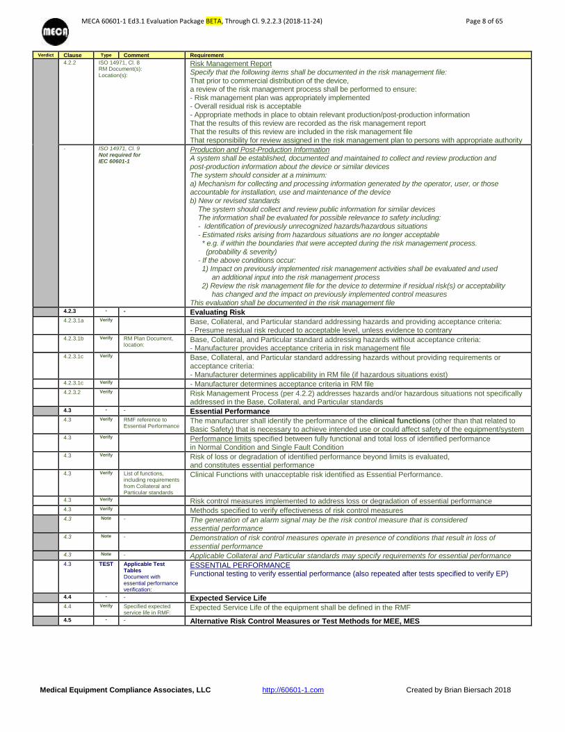
Risk Management Report Specify that the following items shall be documented in the risk management file: That prior to commercial distribution of the device, a review of the risk management process shall be performed to ensure: - Risk management plan was appropriately implemented - Overall residual risk is acceptable - Appropriate methods in place to obtain relevant production/post-production information That the results of this review are recorded as the risk management report That the results of this review are included in the risk management file That responsibility for review assigned in the risk management plan to persons with appropriate authority
- ISO 14971, Cl. 9 Not required for IEC 60601-1
Production and Post-Production Information A system shall be established, documented and maintained to collect and review production and post-production information about the device or similar devices The system should consider at a minimum: a) Mechanism for collecting and processing information generated by the operator, user, or those accountable for installation, use and maintenance of the device b) New or revised standards The system should collect and review public information for similar devices The information shall be evaluated for possible relevance to safety including: - Identification of previously unrecognized hazards/hazardous situations - Estimated risks arising from hazardous situations are no longer acceptable * e.g. if within the boundaries that were accepted during the risk management process. (probability & severity) - If the above conditions occur: 1) Impact on previously implemented risk management activities shall be evaluated and used an additional input into the risk management process 2) Review the risk management file for the device to determine if residual risk(s) or acceptability has changed and the impact on previously implemented control measures This evaluation shall be documented in the risk management file
4.2.3 - - Evaluating Risk
4.2.3.1a Verify Base, Collateral, and Particular standard addressing hazards and providing acceptance criteria: - Presume residual risk reduced to acceptable level, unless evidence to contrary
4.2.3.1b Verify RM Plan Document, location:
Base, Collateral, and Particular standard addressing hazards without acceptance criteria: - Manufacturer provides acceptance criteria in risk management file
4.2.3.1c Verify Base, Collateral, and Particular standard addressing hazards without providing requirements or acceptance criteria: - Manufacturer determines applicability in RM file (if hazardous situations exist)
4.2.3.1c Verify - Manufacturer determines acceptance criteria in RM file
4.2.3.2 Verify Risk Management Process (per 4.2.2) addresses hazards and/or hazardous situations not specifically addressed in the Base, Collateral, and Particular standards
4.3 - - Essential Performance
4.3 Verify RMF reference to Essential Performance
The manufacturer shall identify the performance of the clinical functions (other than that related to Basic Safety) that is necessary to achieve intended use or could affect safety of the equipment/system
4.3 Verify Performance limits specified between fully functional and total loss of identified performance in Normal Condition and Single Fault Condition
4.3 Verify Risk of loss or degradation of identified performance beyond limits is evaluated, and constitutes essential performance
4.3 Verify List of functions, including requirements from Collateral and Particular standards
Clinical Functions with unacceptable risk identified as Essential Performance.
4.3 Verify Risk control measures implemented to address loss or degradation of essential performance
4.3 Verify Methods specified to verify effectiveness of risk control measures
4.3 Note - The generation of an alarm signal may be the risk control measure that is considered essential performance
4.3 Note - Demonstration of risk control measures operate in presence of conditions that result in loss of essential performance
4.3 Note - Applicable Collateral and Particular standards may specify requirements for essential performance
4.3 TEST Applicable Test Tables Document with essential performance verification:
ESSENTIAL PERFORMANCE Functional testing to verify essential performance (also repeated after tests specified to verify EP)
4.4 - - Expected Service Life
4.4 Verify Specified expected service life in RMF:
Expected Service Life of the equipment shall be defined in the RMF
4.5 - - Alternative Risk Control Measures or Test Methods for MEE, MES

MECA 60601-1 Ed3.1 Evaluation Package BETA, Through Cl. 9.2.2.3 (2018-11-24) Page 9 of 65
Medical Equipment Compliance Associates, LLC http://60601-1.com Created by Brian Biersach 2018
Verdict Clause Type Comment Requirement
4.5 Alternative risk for: RM reference to specific risks (ISO 14971) 4.2 Intended use, purpose: 4.3 Hazard identification: 4.4 Risk estimation: 5 Risk evaluation: 6.2 Option analysis: 6.3 Implementation risk control: 6.4 Residual risk evaluation: 6.5 Risk/benefit analysis:
Alternative Risk Control Measures or Test Methods (Equivalent Safety) Only applicable where the equipment/system does not comply with one or more stated requirements in the standard Where an alternative method of demonstrating compliance to the standard is used (Equivalent safety), manufacturer must use scientific data, clinical opinion, or comparative study that the resulting residual risk remains acceptable and is comparable to the standard. This review provided in the risk management file
4.5 Verify Document name, location:
Scientific data, clinical opinion, comparative study
4.6 - - MEE or MES Parts That Contact the Patient
4.6 Verify Parts: Type Applied Part:
Parts of the equipment not rated as applied parts that can contact the patient defined. Requirements for Type B Applied Parts applied, unless assessment identifies the need for Type BF or CF Applied Part to apply.
4.6 RM reference to specific risks (ISO 14971) 4.2 Intended use, purpose: 4.3 Hazard identification: 4.4 Risk estimation: 5 Risk evaluation: 6.2 Option analysis: 6.3 Implementation risk control: 6.4 Residual risk evaluation: 6.5 Risk/benefit analysis:
ME Equipment or ME System Parts That Contact the Patient Evaluation of the likelihood that parts (other than applied parts) will contact the patient provided in the risk management file Such parts will be required to meet all requirements for applied parts, except labeling - Have parts been identified during the risk management process which can come into contact with the patient but fall outside the definition of applied parts? - If so, are all the relevant requirements and tests of this standard applied? - If so, are there residual risks which are not acceptable? - If so, are risk controls measures implemented that make the residual risk acceptable?
4.6 Verify Applied part Type requirements:
All applied part requirements applied, except markings
4.7 - - Single Fault Conditions for MEE
4.7 RM reference to specific risks (ISO 14971) 4.2 Intended use, purpose: 4.3 Hazard identification: 4.4 Risk estimation:
Single Fault Conditions for ME Equipment Under SFC, there shall be no unacceptable risks. The means used to reduce risk shall be adequate to assure that the risk remains acceptable throughout the useful life taking maintenance into consideration as long as the fault will be detected and repaired before harm occurs The RMF shall evaluate possible faults for detectability. - Compliance is determined if the introduction of any of the single fault conditions described in 13.2, one at the time, does not lead directly to the hazardous situations described in 13.1, or any other outcome that results in an unacceptable risk. - Are there single fault conditions which lead directly to hazardous situations described in 13.1 or to risks that are unacceptable?
4.7 Verify (Test)
Simulated physically in Clause 13.4
Failure of any one component at a time that could result in a hazardous situation, including those in 13.1, simulated physically or theoretically
4.7 Verify Risk associated with failure of component during expected service life of ME equipment taken into account to evaluate if a component should be subjected to failure simulation
4.7 Interp - “fault conditions” not limited to Single Fault Conditions, but multiple faults only conducted if likelihood and detection cause it to be considered a normal condition (per WG14).
4.8 - - Components of MEE
4.8 Verify Components not used within ratings:
Component Ratings All components and wiring whose failure could result in a hazardous situation used according to their applicable ratings, except as specified in this standard, or by risk management process.
4.8 RM reference to specific risks (ISO 14971) 4.2 Intended use, purpose: 4.3 Hazard identification: 4.4 Risk estimation: 5 Risk evaluation: 6.2 Option analysis: 6.3 Implementation risk control: 6.4 Residual risk evaluation: 6.5 Risk/benefit analysis:
Components of ME Equipment Only applicable where components used outside their ratings Risk management process assesses components for use outside their ratings provided in the risk management file - Are specific exceptions made for any component of the device under investigation to allow it to be used not in accordance with its specified rating? - If so, are these exceptions formulated as the result of the risk management process? - If so, have inspection or test requirements been formulated to make the hazardous situations acceptable?
4.8 Verify Components used as a Means Of Protection (MOP) assessed for the conditions of the equipment, and
4.8 Verify a) Meet an applicable IEC or ISO standard, or
4.8 Verify b) Where no relevant IEC or ISO standard, ANSI standard or this standard applied
4.8 Verify RM reference to specific risks:
Risk management process assesses components for use as Means Of Protection (MOP)
4.8 Info - If there are neither requirements in this standard nor in an IEC or ISO standard, another applicable source could be used to demonstrate compliance (other standards)
4.8 (Test) - Tests of this standard for motors and transformers considered comprehensive, together with the evaluation of the motor/ transformer insulation system (Documented in Clauses 13.2.8, 13.2.13.3, 15.5.3)
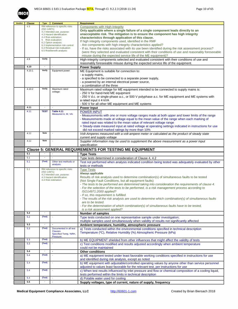
4.9 - - Use of Components With High-Integrity Characteristics in MEE
4.9 Verify High reliability components:
High-Integrity Components used when a fault in a particular component can generate an unacceptable risk
MECA 60601-1 Ed3.1 Evaluation Package BETA, Through Cl. 9.2.2.3 (2018-11-24) Page 10 of 65
Medical Equipment Compliance Associates, LLC http://60601-1.com Created by Brian Biersach 2018
Verdict Clause Type Comment Requirement
4.9 RM reference to specific risks (ISO 14971) 4.2 Intended use, purpose: 4.3 Hazard identification: 4.4 Risk estimation: 5 Risk evaluation: 6.2 Option analysis: 6.3 Implementation risk control: 6.4 Residual risk evaluation: 6.5 Risk/benefit analysis:
Components with High-Integrity Only applicable where a single failure of a single component leads directly to an unacceptable risk. The mitigation is to ensure the component has high integrity characteristics through application of this clause. If high integrity components used, identified in the RMF - Are components with high-integrity characteristics applied? - If so, have the risks associated with its use been identified during the risk assessment process? (were they selected and evaluated consistent with their conditions of use and reasonably foreseeable misuse during the expected service life of the ME equipment)?
4.9 Verify High-integrity components selected and evaluated consistent with their conditions of use and reasonably foreseeable misuse during the expected service life of the equipment.
4.10 - - Power Supply
4.10.1 Verify Equipment power: ME Equipment is suitable for connection to: - a supply mains, - a specified to be connected to a separate power supply, - a powered by an internal electrical power source, - a combination of the three
4.10.2 Verify Maximum rated voltage:
Maximum rated voltage for ME equipment intended to be connected to supply mains is: - 250 V for hand-held ME equipment - 250 V d.c. or single-phase a.c., or 500 V polyphase a.c. for ME equipment and ME systems with a rated input ≤ 4 kVA - 500 V for all other ME equipment and ME systems
4.11 - - Power Input
4.11 TEST Table 4.11 Measured A, W, VA:
POWER INPUT - Measurements with one or more voltage ranges made at both upper and lower limits of the range - Measurements made at voltage equal to the mean value of the range when each marking of rated input was related to the mean value of relevant voltage range = Steady-state measured input at rated voltage at operating settings indicated in instructions for use did not exceed marked ratings by more than 10%
4.11 Note - Volt-Amperes measured with a volt-ampere meter or calculated as the product of steady state current and supply voltage
4.11 Note - Supplier information may be used to supplement the above measurement as a power input specification
Clause 5: GENERAL REQUIREMENTS FOR TESTING ME EQUIPMENT 5.1 - - Type Tests
5.1 - - Type tests determined in consideration of Clause 4, 4.2
5.1 (Test) Other test methods or analysis:
Test not performed when analysis indicated condition being tested was adequately evaluated by other tests or methods
5.1 RM reference to specific risks (ISO 14971) 4.2 Intended use, purpose: 4.3 Hazard identification: 4.4 Risk estimation:
Type Tests Always applicable
Results of risk analysis used to determine combination(s) of simultaneous faults to be tested (Not Single Fault Conditions, but all equipment faults) - The tests to be performed are determined taking into consideration the requirements of clause 4. - For the selection of the tests to be performed, is a risk management process according to ISO14971:2000 applied? - If so, this requirement is fulfilled. - The results of the risk analysis are used to determine which combination(s) of simultaneous faults are to be tested. - For the determination of which combination(s) of simultaneous faults have to be tested, is a risk assessment applied?
5.2 - Number of samples
5.2 (Test) - Type tests conducted on one representative sample under investigation; multiple samples used simultaneously when validity of results not significantly affected
5.3 - - Ambient temperature, humidity, atmospheric pressure
5.3 (Test) Documented in all test Clauses Specified Temp, %RH, Pressure:
a) Tests conducted within the environmental conditions specified in technical description Temperature (ºC), Relative Humidity (%) Atmospheric Pressure (kPa)
5.3 (Test) - b) ME EQUIPMENT shielded from other influences that might affect the validity of tests
5.3 (Test) - c) Test conditions modified and results adjusted accordingly when ambient temperature could not be maintained
5.4 - - Other conditions
5.4 (Test) - a) ME equipment tested under least favorable working conditions specified in instructions for use and identified during risk analysis, except as noted
5.4 (Test) - b) ME equipment with adjustable/controlled operating values by anyone other than service personnel adjusted to values least favorable for the relevant test, per instructions for use
5.4 (Test) - c) When test results influenced by inlet pressure and flow or chemical composition of a cooling liquid, tests performed within the limits in technical description
5.4 (Test) - d) Potable water used for cooling
5.5 - - Supply voltages, type of current, nature of supply, frequency

MECA 60601-1 Ed3.1 Evaluation Package BETA, Through Cl. 9.2.2.3 (2018-11-24) Page 11 of 65
Medical Equipment Compliance Associates, LLC http://60601-1.com Created by Brian Biersach 2018
Verdict Clause Type Comment Requirement
5.5a (Test) Voltage(s): a) Testing voltage(s) were the least favorable of the voltage ratings, per the accompanying documents (or per 4.10.2)
5.5b (Test) Frequency(ies) b) Testing frequency(ies) least favorable of the frequency ratings
5.5c (Test) Ratings/configurations: c) MEE with more than one rated voltage, a.c./ d.c., or external/internal power sources, tested in least favorable conditions (see 5.4)
5.5d (Test) DC Supply: Polarity Influence:
d) MEE intended for connection to d.c. supply mains is only tested with d.c. Influence of polarity on the operation of the MEE considered
5.5e (Test) Configuration: e) MEE tested with alternative accessories and components specified in accompanying documents to address least favorable conditions
5.5f (Test) - f) MEE tested using separate power supply, specified in instructions for use
5.6 - - Repairs and modifications
5.6 (Test) - When failure occurred, or probability of future failure detected during sequence of tests, per agreement with manufacturer, all tests affecting results conducted on a new sample. Alternatively, upon repair and modification of the sample, only the relevant tests conducted
5.7 - - Humidity preconditioning treatment
5.7 (Test) Documented in Clauses 5.7, 8.7.4.1, 8.8.3
ME equipment and/or parts affected by climatic conditions were subjected to a humidity preconditioning prior to tests of Clauses 8.7.4 and 8.8.3 (leakage current and dielectric withstand)
5.7 (Test) Documented in Additional Test Table
Equipment or parts set up completely or partially (covers detached) for preconditioning
5.7 TEST Additional Tests Table Humidity: Temp: Time:
HUMIDITY PRECONDITIONING ME equipment was set up completely or partially, with covers detached, heated to a temperature between T and T + 4 °C for at least 4 h and placed in a humidity chamber with a relative humidity of 93 % ± 3 % and an ambient within 2 °C of T in the range of + 20 °C to + 32 °C for 48 h = Followed by leakage current and dielectric withstand tests of Clauses 8.7.4 and 8.8.3)
5.7 (Test) - When risk management process indicated ME equipment can be exposed to high humidity for extended periods (i.e., out-door use), test time extended proportionally
5.8 - - Sequence of tests
5.8 (Test) - Unless stated otherwise, the tests in this standard are sequenced in such a way that the results of any test do not influence the results of a subsequent test (see also Annex B)
5.9 - - Determination of Applied Parts and Accessible Parts
5.9.1 Verify Applied Parts: Applied Parts Identified by inspection and reference to accompanying documents Equipment positioned in normal use, after opening access covers and removal of parts without a tool
5.9.2 - - Accessible Parts
5.9.2.1, Verify Accessible parts shall not represent a hazard
5.9.2.1, TEST Table 5.9.2 Accessible parts:
ACCESSIBLE PARTS Inspection of equipment Use of the jointed test finger and unjointed test finger with 30 N force, in case of doubt Equipment greater than 45 kg not tilted for access = Accessible parts defined, as necessary
5.9.2.2 TEST Table 5.9.2 Accessible parts:
ACCESSIBLE PARTS Use of the test hook in openings, where it can fit, with a force of 20 N for 10 seconds = Followed by Accessibility test above
5.9.2.3 Verify Actuator parts considered accessible:
Actuators (knobs, actuating electrical controls, etc.) Removable without a tool considered accessible
5.9.2.3 Verify Actuator parts considered not accessible:
Removable only with a tool not considered accessible
Clause 6: CLASSIFICATION OF ME EQUIPMENT AND ME SYSTEMS 6.2 Doc. Classification: Equipment Classification as to protection against electric shock
Class I: Protective Earthing used as part of protection. Class II: Double insulation used. Internally powered: Equipment has the ability to operate without mains power applied.
6.2 Doc. Type Applied Part: Applied Parts Classification as to protection against electric shock Type B: may have connection to earth ground. Type BF: floating with relation to earth ground. Type CF: floating part intended for direct cardiac contact. Defibrillation-Proof (B, BF, CF): Applied Parts additionally Classified as Defibrillation-Proof No Applied Parts: No parts contacting patient to perform intended function
6.3 Doc. IP Rating: Protection against ingress of fluids and particulate matter IPXX Rating, per IEC 60529.
6.4 Doc. Sterilization Method? Sterilization methods Equipment or parts Intended to be sterilized Rating specified (as applicable), according to accompanying documents Examples: ethylene oxide gas, irradiation such as gamma ray, moist heat such as by autoclave, or other methods validated and described by the manufacturer
6.5 Doc. Oxygen Rich Environment?
Oxygen Rich Environment Classified for use with Oxygen specified (See 11.2.2), as applicable

MECA 60601-1 Ed3.1 Evaluation Package BETA, Through Cl. 9.2.2.3 (2018-11-24) Page 12 of 65
Medical Equipment Compliance Associates, LLC http://60601-1.com Created by Brian Biersach 2018
Verdict Clause Type Comment Requirement
6.6 Doc. Continuous or Duty Cycle?
Mode of Operation Continuous Operation, Non-Continuous Operation (such as a duty cycle)
Clause 7: ME EQUIPMENT IDENTIFICATION, MARKING, AND DOCUMENTS 7.1.1 Info - Usability (requirements removed in Amendment 1)
7.1.2 TEST Table 7.1.2 Markings identified:
LEGIBILITY OF MARKINGS Test of markings required in 7.2 - 7.6. Observer: visual acuity of 0 on the log Minimum Angle of Resolution (log MAR) scale or 6/6 (20/20) and is able to read N6 of Jaeger test card in normal room lighting condition (~500lx). Marking read at ambient luminance (100 lx to 1,500 lx), positioned for intended position of the operator, or at any point within the base of a 30° cone (if not defined), at a distance of 1 m. = Observer correctly identifies required markings
7.1.3 TEST Table 7.1.3 Markings tested:
DURABILITY OF MARKINGS Required markings can be removed only with a tool or by appreciable force, are durable, and remain clearly legible during expected service life of me equipment in normal use. Marking rubbed by hand with a cloth rag soaked with each of the following, for 15 sec.: Distilled water, ethanol (96%) C2H6O, and Isopropyl alcohol C3H8O. = Followed by Legibility test above
7.2 - - Marking on The Outside of ME Equipment or Parts
7.2.1 Verify Minimum Requirements For Marking On ME Equipment If size or the nature of enclosure does not allow affixation of all required markings, at least provide - 7.2.2 (manufacturer, model, serial number, date of manufacture, software rev. identifier), - 7.2.5 (external power supply), - 7.2.6 (Class II), 7.2.10 (Applied Parts), - 7.2.13 (Physiological effects), as applicable, shall be affixed.
7.2.1 Verify Remaining markings fully recorded in accompanying documents
7.2.1 Verify Markings applied to individual packaging when impractical to apply to me equipment
7.2.1 Verify "Single Use Only" / “Do Not Reuse”/ Symbol 28, Table D1
- Single use item marked
7.2.2 - - Identification: ME Equipment marked with the following.
7.2.2 Verify - Name or trademark - Contact information of the manufacturer
7.2.2 Verify - Model or type reference
7.2.2 Verify - Serial number or lot or batch identifier (readable or identification by technology – RFID, etc.)
7.2.2 Verify - Date of manufacture or use by date, if applicable
7.2.2 Verify Unless misidentification does not present unacceptable risk (misidentification could lead to a hazardous situation), detachable components marked with at least: - Name or trademark of the manufacturer - Model or type reference
7.2.2 RM reference to specific risks (ISO 14971) 4.2 Intended use, purpose: 4.3 Hazard identification: 4.4 Risk estimation: 5 Risk evaluation: 6.4 Residual risk evaluation:
Identification Only applicable where equipment or accessories not marked with manufacturer/model If not marked, the risk management file includes an assessment of the risks relating to misidentification of all detachable parts. - ME Equipment and its detachable parts not marked with the name or trademark of the manufacturer and with a Model or Type reference does not present an unacceptable risk?
7.2.2 Verify Unique identifier (Rev):
- Software identified with a unique identifier (not required on outside of equipment, can be only available to designated/service people)
7.2.3 Verify Consult Accompanying Documents - Table D1, Symbol 11 MAY be used, to advise operator to consult acompanying documents:
- Table D2, safety sign 10 MUST be used if risk management uses the acompanying documents to reduce risk to an acceptable level, but only when the manufacturer uses the IFU as a risk control measure for a specific risk
7.2.4 Verify Accessories
inspected: Accessories: - Marked with name or trademark - Contact information of their manufacturer
7.2.4 Verify - Model or type reference
7.2.4 Verify - Serial number or lot or batch identifier
7.2.4 Verify - Date of manufacture or use by date (if applicable)
7.2.4 Verify - Markings applied to individual packaging, when not practical to apply to accessories
7.2.5 - - ME Equipment intended to receive power from other equipment Provided with one of the following:
MECA 60601-1 Ed3.1 Evaluation Package BETA, Through Cl. 9.2.2.3 (2018-11-24) Page 13 of 65
Medical Equipment Compliance Associates, LLC http://60601-1.com Created by Brian Biersach 2018
Verdict Clause Type Comment Requirement
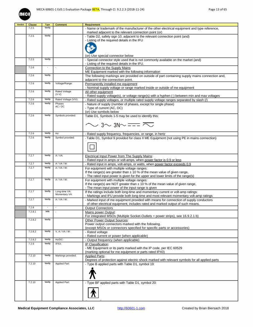
7.2.5 Verify - Name or trademark of the manufacturer of the other electrical equipment and type reference, marked adjacent to the relevant connection point (or)
7.2.5 Verify - Table D2, safety sign 10, adjacent to the relevant connection point (and) - Listing of the required details in the IFU
(or) Use special connector below
7.2.5 Verify - Special connector style used that is not commonly available on the market (and) - Listing of the required details in the IFU.
7.2.6 - - Connection to the Supply Mains ME Equipment marked with the following information
7.2.6 Verify The following markings are provided on outside of part containing supply mains connection and, adjacent to the connection point.
7.2.6 Verify Voltage/Range: Permanently installed me equipment - Nominal supply voltage or range marked inside or outside of me equipment
7.2.6 Verify Rated Voltage (V-V):
All other equipment - Rated supply voltage(s), or voltage range(s) with a hyphen (-) between min and max voltages
7.2.6 Verify Rated Voltage (V/V): - Rated supply voltages, or multiple rated supply voltage ranges separated by slash (/)
7.2.6 Verify Phases AC / DC
- Nature of supply (number of phases, except for single phase) - Type of current (AC, DC) (or) Use symbols below
7.2.6 Verify Symbols provided: Table D1, Symbols 1-5 may be used to identify this:
7.2.6 Verify Hz: - Rated supply frequency, frequencies, or range, in hertz
7.2.6 Verify Symbol provided: - Table D1, Symbol 9 provided for class II ME Equipment (not using PE in mains connection)
7.2.7 Verify A / VA: Electrical Input Power from The Supply Mains:
- Rated input in amps or volt-amps, when power factor is 0.9 or less
7.2.7 Verify A / VA / W: - Rated input in amps, volt-amps, or watts, when power factor exceeds 0.9
7.2.7 Verify A / VA / W: For equipment with multiple voltage ranges: If the range(s) are greater than ± 10 % of the mean value of given range, - The rated input power is given for the upper and lower limits of the range(s)
7.2.7 Verify A / VA / W: For equipment with multiple voltage ranges: If the range(s) are NOT greater than ± 10 % of the mean value of given range, - The mean input power of the input range is given
7.2.7 Verify Long-time VA: Momentary VA:
If the ratings include both long-time and momentary current or volt-amp ratings: - Markings and IFU provide both long-time and most relevant momentary volt-amp ratings
7.2.7 Verify A / VA / W: - Marked input of me equipment provided with means for connection of supply conductors of other electrical equipment, includes rated and marked output of such means.
7.2.8 - - Output Connectors
7.2.8.1 Info - Mains power Output: For integrated MSOs (Multiple Socket-Outlets = power strips), see 16.9.2.1 b)
7.2.8.2 Verify Other Power Output Sources: Power output connectors marked with the following. (except MSOs or connectors specified for specific parts or accessories)
7.2.8.2 Verify V, A / VA / W: - Rated voltage - Rated current or power (when applicable)
7.2.8.2 Verify Hz/DC: - Output frequency (when applicable)
7.2.9 Verify IPXX: IP Classification: - ME Equipment or its parts marked with the IP code, per IEC 60529 (marking optional for me equipment or parts rated IPX0)
7.2.10 Verify Markings provided: Applied Parts: Degrees of protection against electric shock marked with relevant symbols for all applied parts
7.2.10 Verify Applied Part: - Type B applied parts with Table D1, symbol 19:
7.2.10 Verify Applied Part: - Type BF applied parts with Table D1, symbol 20:

MECA 60601-1 Ed3.1 Evaluation Package BETA, Through Cl. 9.2.2.3 (2018-11-24) Page 14 of 65
Medical Equipment Compliance Associates, LLC http://60601-1.com Created by Brian Biersach 2018
Verdict Clause Type Comment Requirement
7.2.10 Verify Applied Part: - Type CF applied parts with Table D1, symbol 21:
7.2.10 Verify Applied Part: - Defibrillation-proof applied parts marked with Table D1, symbols 25-27:
7.2.10 Verify Marking location: Proper symbol marked adjacent to or on connector for applied part, except:
- If no connector, then marked on applied part - If connector used for multiple applied parts with different ratings, marked on applied part - If isolation for BF or CF is not provided in the equipment, but in the applied part, marked on the applied part
7.2.10 Verify Relevant connector: - Table D2, Safety sign 2 placed near connector if part of defib-proof protection is in patient cable
7.2.10 Verify Explanation in IFU: - IFU indicates that the protection of ME Equipment against effects of a cardiac defibrillator discharge
depends on use of proper cables, as applicable.
7.2.11 Verify Mode of operation: ME Equipment suitable for continuous operation
7.2.11 Verify Duty Cycle: If NOT continuous use, duty cycle appropriately marked to provide maximum “on” and “off” time.
7.2.11 (US)
Verify Long time operation / Momentary operation
- X-Ray systems marked as “long time operation” or “momentary operation” (NFPA 70)
7.2.12 Verify Fuses: Markings provided adjacent to accessible fuse-holder
7.2.12 Verify Type: - Fuse type
7.2.12 Verify V, A: - Voltage rating - Current rating
7.2.12 Verify Fast / Slow, A breaking capacity:
- Operating speed (letter or color code) - Breaking capacity (see Clause 8.11.5 for requirement of high breaking capacity fuses)
7.2.13 Verify Physiological effects: Physiological Effects (Safety Sign and Warning Statements): - ME Equipment producing physiological effects, not obvious to the operator, and can cause harm to the patient or operator provides suitable safety sign in a prominent location.
7.2.13 RM reference to specific risks
(ISO 14971) 4.2 Intended use, purpose: 4.3 Hazard identification: 4.4 Risk estimation: 5 Risk evaluation: 6.3 Implementation risk control:
Physiological Effects (Safety Signs and Warning) Only applicable where there are physiological effects that can cause harm to the patient and are not obvious to the operator Nature of hazard and precautions for avoiding or minimizing the associated risk described in IFU. (Risk management to address risk of harm) - Do the instructions for use describe the nature of the hazard and the precautions for avoiding it or minimizing the associated risk?
7.2.14 Verify High Voltage Terminal Devices: When provided on the outside of ME Equipment, accessible without the use of a tool, - Marked with Table D1, symbol 24
7.2.15 Verify Cooling requirements: Cooling Conditions: - Requirements for cooling provisions marked, if applicable
7.2.17 Verify Special handling instructions:
Protective Packaging: - Packaging marked with special handling instructions for transport and/or storage, if applicable
7.2.17 Verify Environmental conditions:
- Permissible environmental conditions (for transport and storage) marked on outside of packaging (includes Temperature, Humidity, and Atmospheric Pressure ranges)
7.2.17 Verify Safety sign provided: When premature unpacking of me equipment could result in an unacceptable risk, - Packaging marked with a suitable safety sign
7.2.17 RM reference to specific risks (ISO 14971) 4.2 Intended use, purpose: 4.3 Hazard identification: 4.4 Risk estimation: 5 Risk evaluation: 6.3 Implementation risk control: 6.4 Residual risk evaluation:
Protective Packing Only applicable where premature unpacking of the equipment could result in an unacceptable RISK (e.g. humidity sensitive, hazardous substances) Risk management file includes the assessment to determine risk of premature unpacking of the ME Equipment or its parts , that could result in an unacceptable risk. - Can premature unpacking of ME Equipment or its parts result in an unacceptable risk? - Is the packaging marked with a suitable safety sign?
7.2.17 Verify Sterile, Method: Packaging of sterile ME Equipment or accessories, - Marked sterile and indication of the method of sterilization
MECA 60601-1 Ed3.1 Evaluation Package BETA, Through Cl. 9.2.2.3 (2018-11-24) Page 15 of 65
Medical Equipment Compliance Associates, LLC http://60601-1.com Created by Brian Biersach 2018
Verdict Clause Type Comment Requirement
7.2.18 Verify Max supply pressure: External Pressure Source: Marked on me equipment adjacent to each input connector, - Rated maximum supply pressure from an external source
7.2.18 Verify Flow rate: - Rated flow rate required to meet basic safety and essential performance
7.2.19 Verify Symbol provided: Functional Earth Terminals: - Marked with Table D1, Symbol 7
7.2.20 Verify Mark provided: Removable Protective Means:
- Marked to indicate the necessity for replacement when the function is no longer needed
7.2.21 Verify Equipment mass in kg: Mass of Mobile Equipment: - Marked with its mass, including its safe working load in kilograms (Marked in a way that’s obvious that it applies to the entire mobile ME Equipment, including maximum safe working load, and separate from part load ratings)
7.2.22 (US)
Verify Colors of Medical Gas Cylinders: Cylinders containing medical gases and their connection points colored in accordance with NFPA99
7.3 - - Marking on the inside of me equipment or me equipment parts
7.3.1 Verify W: Heating Elements or Lamp Holders (designed for use with heating lamps): - Maximum power loading marked near or in the heater
7.3.1 Verify - A marking referring to accompanying documents provided, where they can be changed only by service personnel using a tool
(or)
7.3.2 Verify High Voltage Parts: - Table D1, Symbol 24 (or) Table D2, safety sign 3 used to mark presence of high voltage parts
(or)
7.3.2 Note - Risk management could determine that the safety sign is the most appropriate choice if the personnel exposed to the high voltage parts have minimal training or might otherwise be unaware that it is present
7.3.3 Verify Type, mode of insertion:
Batteries: - Type of battery and mode of insertion marked
7.3.3 Verify Identifying mark: - An identifying marking provided referring to instructions in IFU for batteries intended to be changed only by service personnel using a tool
7.3.3 Verify Warning provided: - A warning provided indicating replacement of lithium batteries or fuel cells IF incorrect replacement would result in an unacceptable risk (in addition to reference to IFU)
7.3.3 RM reference to specific risks (ISO 14971) 4.2 Intended use, purpose: 4.3 Hazard identification: 4.4 Risk estimation: 5 Risk evaluation: 6.3 Implementation risk control:
Batteries Only applicable to equipment with batteries used to operate the equipment (excludes coin cells for memory backup) Risk management file includes an assessment to determine if the replacement of lithium batteries or fuel cells leads to an unacceptable risk if replaced incorrectly. If so, marking is required. - Are there lithium batteries or fuel cells which are incorporated where incorrect replacement could result in an unacceptable risk? - If so, is there a warning indicating that replacement by inadequately trained personnel could result in a hazard?
7.3.3 Verify Warning provided in IFU:
- Accompanying documents contain a warning indicating the replacement of lithium batteries or fuel cells by inadequately trained personnel could result in a hazard, if risk is determined (above)
7.3.4 Verify Spec. adjacent to component, Reference to IFU
Fuses, (Replaceable) Thermal Cut-Outs, and Over-Current Releases: - If ONLY accessible by tool, Identified by specification adjacent to component (Voltage, Current, Operating speed, Size, Breaking capacity) - (or) Reference to IFU, with specifications provided
7.3.4 Verify V, A: - Voltage rating - Current rating
7.3.4 Verify Fast/Slow, mm, High breaking capacity A:
- Operating speed(s) - Size - Breaking capacity (see Clause 8.11.5 for requirement of high breaking capacity fuses)
7.3.5 Verify Protective Earth Terminals: - Marked with Table D1, Symbol 6

MECA 60601-1 Ed3.1 Evaluation Package BETA, Through Cl. 9.2.2.3 (2018-11-24) Page 16 of 65
Medical Equipment Compliance Associates, LLC http://60601-1.com Created by Brian Biersach 2018
Verdict Clause Type Comment Requirement
7.3.5 Verify -Markings on or next to protective earth terminals -Not applied to parts requiring removal to make the connection -Remain visible after connection made -Not required for internal PE connections, but not precluded
7.3.6 Verify Functional Earth Terminals: Table D1, Symbol 7 marked on functional earth terminals
7.3.7 Verify Terminal markings
provided: Supply Terminals: - Conductors marked adjacent to terminals
7.3.7 RM reference to specific risks (ISO 14971) 4.3 Hazard identification:
Supply Terminals Only applicable to permanently installed equipment If not marked, the RMF includes an assessment of the risks resulting from misconnections - Are Terminals for supply conductors marked adjacent to the terminals? - If not, does the identification of known or foreseeable hazards (risk management file) demonstrate that no hazardous situation can result if connections are interchanged?
7.3.7 Verify Terminal markings included in IFU, when equipment too small for markings
7.3.7 Verify - Neutral supply terminal conductor in permanently installed equipment marked with Table D3 , Code 1
N 7.3.7 Verify Marking for connection to a 3-phase supply, complies with IEC 60445
7.3.7 Verify Markings on or adjacent to electrical connection points Not applied to parts requiring removal to make connection Markings remain visible after connection made
7.3.8 Verify Temperatures of Supply Terminals: - Marked at the point of supply connections “For supply connections, use wiring materials suitable for at least X °C” (or equivalent)
7.3.8 Verify Statement not applied to parts requiring removal to make the connection Statement clearly legible after connections made
7.4 - - Marking of controls and instruments
7.4.1 Verify Power Switches: Switches for “on” & “off” positions to control power to ME Equipment/parts (including mains switches) - Marked with Table D1, Symbols 12 and 13, for Mains on/off
(or)
7.4.1 Verify - Indicated by an adjacent indicator light, (or)
7.4.1 Verify - indicated by other unambiguous means
7.4.1 Verify - Push button “on/off” switches with bi-stable positions marked with Table D1, Symbol 14
(and)
7.4.1 Verify - Status indicated by adjacent indicator light (or)
7.4.1 Verify - Status indicated by other unambiguous means
7.4.1 Verify - Push button “on/off” switches with momentary on positions marked with Table D1, Symbol 15
(or)
7.4.1 Verify - Status indicated by adjacent indicator light (or)
7.4.1 Verify - Status indicated by other unambiguous means
7.4.2 Verify Control Devices: - Different positions of control devices/switches indicated by figures, letters, or other visual means, such as Table D1, Symbols 16 and 17 -Control functionality, but not mains power to the equipment
Part ON Part OFF
7.4.2 RM reference to specific risks (ISO 14971) 4.2 Intended use, purpose: 4.3 Hazard identification: 4.4 Risk estimation: 5 Risk evaluation: 6.2 Option analysis: 6.3 Implementation risk control:
Control Devices Only applicable where a change in a control setting in normal use could result in an unacceptable risk to the patient Risk management file identifies controls, where a change in setting in normal use results in an unacceptable risk - In normal use, can the change of the setting of a control result in an unacceptable risk to the patient? - If so, review the manufacturers risk management file for risk analysis, risk evaluation, and where necessary implementation of risk control.
7.4.2 Verify Indicating device: When determined that the change of control settings could result in an unacceptable risk, - Controls provided with an associated indicating device (or)

MECA 60601-1 Ed3.1 Evaluation Package BETA, Through Cl. 9.2.2.3 (2018-11-24) Page 17 of 65
Medical Equipment Compliance Associates, LLC http://60601-1.com Created by Brian Biersach 2018
Verdict Clause Type Comment Requirement
7.4.2 Verify - An indication of direction in which magnitude of the function changes
7.4.2 Verify Control device or switch that brings the ME Equipment into the "stand-by" condition, - Marked with Table D1, Symbol 29 -Control functionality, but not mains power to the equipment
7.4.3 Verify Units of Measurement:
Numeric indications of parameters on ME Equipment expressed in SI units, according to ISO 80000-1 (Base quantities listed in Table 1 expressed in the indicated units)
7.4.3 Verify Application of SI units, their multiples, and certain other units, ISO 80000-1 applied
7.4.3 (Test) Documented in Clauses 7.1.2, 7.1.3
All Markings in 7.4 comply with 7.1.2 (legibility of markings) and 7.1.3 (durability of markings)
7.5 - - Safety signs
7.5 Verify Safety sign with established meaning used (per ISO 7010)(see Table D2)
7.5 RM reference to specific risks (ISO 14971) 4.2 Intended use, purpose: 4.3 Hazard identification: 4.4 Risk estimation: 5 Risk evaluation: 6.3 Implementation risk control:
Safety Signs Only applicable when safety signs used
Risk management process identifies markings used to convey a warning, prohibition or mandatory action that mitigate a risk not obvious to the operator - Is marking used to convey a warning, prohibition or mandatory action that mitigates a risk that is not obvious to the operator? - If so, review the manufacturers risk management file for risk analysis, risk evaluation and where necessary implementation of risk control.
7.5 Verify If insufficient space on ME Equipment for sign and statement, it may be placed in the IFU
7.5 Verify Safety signs used: Specified colors in ISO 3864-1 used for safety signs (see Table D2)
D2, #2 D2, #4 D2, #9 General warning General prohibition General mandatory action
7.5 Verify Safety notices include appropriate precautions or instructions on how to reduce risk(s)
7.5 Verify Safety signs including any supplementary text or symbols described in instructions for use
7.5 Verify Language acceptable to the intended operator
7.6 Verify - Symbols
7.6.1 Verify Symbols defined: Explanation of Symbols: Meanings of symbols used for marking described in IFU
7.6.2 Info Symbols from Annex D: Required symbols shall meet the referenced IEC and ISO standards in Annex D
7.6.3 Verify Symbols For Controls and Performance: Conform to IEC or ISO publications, as applicable
7.7 - - Colours of the insulation of conductors
7.7.1 Verify Protective earth conductor: Identified throughout length by green and yellow insulation
7.7.2 Verify Protective earth connections: All wiring that is part of the protective earth circuit (carrying the protective earth connection to protectively earthed parts) identified by green & yellow, at least at their termination points
7.7.3 Verify Green and yellow insulation: Only used for: - Conductors in the protective earth circuit, - Potential equalization circuit conductors, - Functional earth conductors
7.7.4 Verify Neutral conductor: Insulation of neutral conductor(s) of the (mains) power supply cord colored light blue (per IEC 60227 and IEC 60245)
7.7.5 Verify Power supply cord conductors: Insulation of conductors in the power supply cord (other than the neutral conductor) in accordance with IEC 60227 or IEC 60245 (1 Phase: Brown)
7.8 - - Indicator Lights and controls
7.8 Note Color alone should not be used to convey important information. Redundant means recommended.
7.8.1 Verify Colours of indicator lights - RED: indicating that immediate user intervention is required (dangerous situation) (not applicable for alpha-numeric displays) - YELLOW: Indicating that “prompt” user action or attention required (caution) - GREEN: Normal situation, equipment ready for use (See IEC 60601-1-8 for visual alarm requirements)
7.8.2 Verify Colours of controls: Color red only used for controls that interrupt a function, in case of a dangerous condition
7.9 - - Accompanying documents
7.9.1 - - General
7.9.1 Verify ME Equipment provided with documents containing instructions for use, and a technical description
7.9.1 - - Accompanying documents identify ME Equipment by the following, as applicable:
7.9.1 Verify Name / Contact Info: - Name or trade-name of manufacturer - Contact information for the responsible organization -Intended environments of use

MECA 60601-1 Ed3.1 Evaluation Package BETA, Through Cl. 9.2.2.3 (2018-11-24) Page 18 of 65
Medical Equipment Compliance Associates, LLC http://60601-1.com Created by Brian Biersach 2018
Verdict Clause Type Comment Requirement
7.9.1 Verify Model/Type: - Model or type reference
7.9.1 Verify If accompanying documents provided electronically, Usability engineering process determines what’s required in hard copy or markings on the equipment
7.9.1 Verify - Specify special skills, training, and knowledge required by operator or responsible organization - Environmental restrictions on locations of use
7.9.1 Verify - Written at a level consistent with education, training, and other needs of those they are intended for
7.9.2 - - Instructions for Use (IFU)
7.9.2.1 - - General
7.9.2.1 Verify Intended use: - Intended use of me equipment, as intended by the manufacturer
7.9.2.1 Verify - Frequently used functions
7.9.2.1 Verify - Any known contraindication(s) of the equipment
7.9.2.1 Verify - Name or trademark of the manufacturer - Address of the manufacturer
7.9.2.1 Verify - Model or type reference
7.9.2.1 Verify - Parts of the ME Equipment that are not to be serviced or maintained while in use with the patient
7.9.2.1 Verify When the patient is an intended operator, IFU indicate: (patient partially or fully operating, patient becomes operator, per intended use)
7.9.2.1 Verify - That the patient is an intended operator
7.9.2.1 Verify - Warning against servicing and maintenance while the me equipment is in use
7.9.2.1 Verify - Which functions the patient can safely use (and) - Where applicable, which functions the patient cannot safely use (and)
7.9.2.1 Verify - What maintenance the patient can perform (change batteries, etc.)
7.9.2.1 Verify (see below) Classifications as in Clause 6:
(6.2) Info - - Classification (Class I, Class II, Internally Powered Equipment)
(6.2) Info - - Type Applied Parts (B, BF, CF, Defib-proof)
(6.3) Info - - IPXX (protection against the ingress of water, particulate matter)
(6.4) Info - - Method(s) of sterilization (if applicable)
(6.5) Info - - Suitability for use in an Oxygen rich environment (if applicable)
(6.6) Info - - Mode of operation
7.9.2.1 Verify (see below) All markings per Clause 7.2:
(7.2.2) Info - - Single use items specified
(7.2.2) Info - - Name or trademark
(7.2.2) Info - - Contact information of the manufacturer
(7.2.2) Info - - Model or type reference
(7.2.2) Info - - Serial number or lot or batch identifier (description)
(7.2.2) Info - - Date of manufacture or use by date (description)
(7.2.2) Info - Detachable components (unless no risk from misidentification):
(7.2.2) Info - - Name or trademark of the manufacturer
(7.2.2) Info - - Model or type reference
(7.2.2) Info - - Software identified with a unique identifier (description)
(7.2.3) Info - - Consult accompanying documents
(7.2.4) Info - - Accessories:
(7.2.4) Info - - Name or trademark
(7.2.4) Info - - Manufacturer contact information
(7.2.4) Info - - Model or type reference
(7.2.4) Info - - Serial number or lot or batch identifier (description)
(7.2.4) Info - - Date of manufacture or use by date (description)
(7.2.5) Info - - Power from other equipment:
(7.2.5) Info - - Name/trademark of manufacturer and type reference of other electrical equipment (supplying power)
(7.2.6) Info - - Nominal supply voltage or range
(7.2.6) Info - - Nature of supply (number of phases, except for single phase)
(7.2.6) Info - - Type of current (AC, DC)
(7.2.6) Info - - Rated supply frequency, frequencies, or range, in hertz
(7.2.6) Info - - Rated input in amps, volt-amps, or watts
(7.2.8.1) Info - - MSO output Mains voltage, current or power, frequency
(7.2.9) Info - - IPXX (protection against the ingress of particulate matter, water)
(7.2.10) Info - - Type Applied Parts (B, BF, CF, Defib-proof)
(7.2.11) Info - - Mode of operation (if not continuous) - duty cycle on/off times
(7.2.12) Info - - Fuse type, voltage, current rating, operating speed, breaking capacity
(7.2.13) Info - - Physiological effects (if applicable)
(7.2.15) Info - - Requirements for cooling provisions (if applicable)
(7.2.17) Info - - Packaging with special handling (if applicable)
(7.2.17) Info - - Permissible environmental conditions
(7.2.17) Info - - Information for when premature unpacking of me equipment could result in an unacceptable risk
(7.2.17) Info - - Information on equipment or accessories provided sterile (if applicable)
(7.2.18) Info - - Rated maximum supply pressure from an external source (if applicable)

MECA 60601-1 Ed3.1 Evaluation Package BETA, Through Cl. 9.2.2.3 (2018-11-24) Page 19 of 65
Medical Equipment Compliance Associates, LLC http://60601-1.com Created by Brian Biersach 2018
Verdict Clause Type Comment Requirement
(7.2.20) Info - - Specification of removable protective means (if applicable)
(7.2.21) Info - - Mass of mobile equipment, including its safe working load (parts serving for support or suspension of patient/operators is the mass of the patients/operators plus the mass of accessories intended to be supported/suspended by the equipment or equipment parts) in kilograms
7.9.2.1 Verify Explanation of safety signs and symbols marked on ME Equipment
7.9.2.1 Verify Instructions for use are in a language acceptable to the intended operator
7.9.2.2 Verify Warning and Safety Notices - All warning and safety notices defined in IFU
7.9.2.2 Verify - Warning statement for class I me equipment included: “WARNING: To avoid risk of electric shock, this equipment must only be connected to a supply mains with protective earth”
7.9.2.2 Verify - Warnings of significant risks of reciprocal interference posed by me equipment during specific investigations or treatments
7.9.2.2 Verify - Information on potential electromagnetic or other interference and advice on how to avoid or minimize such interference
7.9.2.2 Verify - Class I equipment with and internal electrical power source shall state that the internal electrical power source is to be used if the integrity of the PE conductor or the protective earthing system in the installation is in doubt.
7.9.2.2 Verify - Warning statement for ME Equipment/Systems supplied with an integral MSO (multiple socket-outlet)
7.9.2.2 Verify - Responsible organization referred to this standard, for the requirements applicable to ME Systems
7.9.2.3 Verify ME Equipment Specified for Connection to a Separate Power Supply: For Equipment with separate power supply - Power supply specified as part of the ME Equipment (or) - Combination of Equipment and power supply specified as an ME System
7.9.2.4 Verify Electrical Power Source: - Warning statement for mains powered ME Equipment with additional power source, not automatically maintained in a fully usable condition (indicating necessity for periodic checking or replacement of power source)
7.9.2.4 RM reference to specific risks (ISO 14971) 4.2 Intended use, purpose: 4.3 Hazard identification: 4.4 Risk estimation: 5 Risk evaluation: 6.3 Implementation risk control:
Electrical Power Source Only applicable to equipment with batteries intended to operate the equipment (excludes coin cells for memory backup) Assessment of risk(s) associated with leakage of batteries provided in the risk management file - If leakage from a battery would result in an unacceptable risk, do the instructions for use include a warning to remove the battery if the ME Equipment is not likely to be used for some time? - If so, review the manufacturer’s risk management file for risk analysis, risk evaluation and where necessary implementation of risk control. - If loss of power would result in an unacceptable risk, do the instructions for use include a Warning that the ME Equipment must be connected to an appropriate power source? - If so, review the manufacturers risk management file for risk analysis, risk evaluation, and where necessary, implementation of risk control.
7.9.2.4 Verify “Remove the battery if the ME Equipment is not likely to be used for some time”
- Warning to remove the battery if the me equipment is not likely to be used for some time, where there is an unacceptable risk
7.9.2.4 Verify Battery specifications: - Specifications of any replaceable internal electrical power source
7.9.2.4 Verify Specified power source:
- Warning that ME Equipment must be connected to an appropriate power source, when loss of power would result in an unacceptable risk
7.9.2.5 Verify ME Equipment Description - Description of ME Equipment - Functions - Significant physical and performance characteristics - (If applicable) Expected positions of operator, patient, other persons near ME Equipment, normal use
7.9.2.5 Verify - Information provided on materials and ingredients that the patient or operator is exposed to, if exposure can constitute an unacceptable risk
7.9.2.5 Verify - Specified restrictions on what other equipment or network/data couplings (other than those forming ME System) the SIP/SOPs may be connected to
7.9.2.5 Verify - Indication of all applied parts
7.9.2.6 Verify Installation: ME Equipment or its parts requiring installation require the following - Reference to where the installation instructions may be found (or) - Contact information for qualified personnel to perform the installation - Statement that manufacturer/installer/assembler is responsible for the effect on basic safety/reliability/performance only if
- Appropriately trained personnel are used, electrical installation of the room complies with requirements, and ME Equipment or System is used in accordance with the IFU
7.9.2.7 Verify Isolation From The Supply Mains: - Indication not to position equipment to make it difficult to operate the disconnection device, when appliance coupler/mains plug used for mains disconnection
7.9.2.8 Verify Start-Up Procedure: - Necessary information provided for operator to bring me equipment into operation (initial control settings, connection to or positioning of patient, etc.)

MECA 60601-1 Ed3.1 Evaluation Package BETA, Through Cl. 9.2.2.3 (2018-11-24) Page 20 of 65
Medical Equipment Compliance Associates, LLC http://60601-1.com Created by Brian Biersach 2018
Verdict Clause Type Comment Requirement
7.9.2.9 Verify Operating Instructions: - Information provided to operate ME Equipment in accordance with specifications - Functions of controls, displays, signals - Sequence of operation - Connection and disconnection of detachable parts and accessories - Replacement of materials consumed in operation
7.9.2.9 Verify - Meanings of figures, symbols, warning statements, abbreviations, indicator lights
7.9.2.10 Verify Messages: - All system, error, and fault messages, unless they are self-explanatory - Explanation of messages including important causes and possible action(s) to resolve the problem
7.9.2.11 Verify Shutdown Procedure: - Information to safely terminate operation of ME Equipment
7.9.2.12 Verify Cleaning, Disinfection, and Sterilization: - For parts or accessories that can be contaminated through contact with patient, body fluids, or expired gasses in normal use, - Cleaning, disinfection, sterilization methods that may be used - Applicable parameters that can be tolerated by me equipment parts or accessories specified (e.g. temperature, pressure, humidity, time limits, number of cycles)
7.9.2.12 Verify Not required if marked for single use, except when manufacturer specifies it to be cleaned, disinfected, or sterilized before use
7.9.2.13 Verify Maintenance: - Preventive inspection, maintenance, calibration along with its frequency (if applicable)
7.9.2.13 Verify - Information provided for safe performance of such routine maintenance necessary to ensure continued safe use of me equipment
7.9.2.13 Verify - Identify parts requiring preventive inspection and maintenance to be performed by service personnel including periods of application (details of actual performance not necessary)
7.9.2.13 Verify - Instructions provided to ensure adequate maintenance of rechargeable batteries, maintained by anyone other than service personnel
7.9.2.14 Verify Accessories, Supplementary Equipment, Used Material: - List of accessories, detachable parts, and materials intended for use with the ME Equipment
7.9.2.14 Verify Other equipment providing power to ME System sufficiently specified (e.g. part number, rated voltage, max/min power, protection class, continuous/duty cycle)
7.9.2.15 Verify Advice: Environmental Protection: - Advice on proper disposal of waste products, residues, etc. - Advice on proper disposal of ME Equipment and accessories at the end of their expected service life
7.9.2.16 Verify Reference to Technical Description: - Information specified in 7.9.3 (see below) or identify where it can be found (such as service manual)
7.9.2.17 Verify ME Equipment Emitting Radiation: ME Equipment emitting radiation for medical purposes - Indication of the nature, type, intensity and distribution of the radiation (as appropriate)
7.9.2.18 Verify ME Equipment and Accessories Supplied Sterile: - Indicate that they have been sterilized - Indicate the method of sterilization
Verify - Indicate the necessary instructions in the event of damage to the sterile packaging - Details of the appropriate methods of re-sterilization (if applicable)
7.9.2.19 Verify IFU Identifier (revision):
Unique Version Identifier: - IFU contains a unique version identifier
7.9.3 - - Technical description
7.9.3.1 - - General: Provide all essential data for safe operation (see below)
7.9.3.1 Verify - Permissible environmental conditions for use, transport, and storage (from 7.2.17)
7.9.3.1 Verify All characteristics of ME Equipment - Range(s), accuracy, precision of displayed values (or where they can be found)
7.9.3.1 Verify - Any special installation requirements
7.9.3.1 Verify - Cooling liquids, range of inlet pressure, flow, chemical composition
7.9.3.1 Verify - Means of isolating ME Equipment from supply mains, if not incorporated in ME Equipment
7.9.3.1 Verify - Describe means for checking oil level, for partially sealed oil filled ME Equipment or parts
7.9.3.1 Verify Warning statement provided:
- Warning statement to address hazards from unauthorized modification of ME Equipment: “WARNING: No modification of this equipment is allowed” (or) “WARNING: Do not modify this equipment without authorization of the manufacturer” (or) “WARNING: If this equipment is modified, appropriate inspection and testing must be conducted to ensure continued safe use of the equipment”
7.9.3.1 Verify - Information about any essential performance - Any necessary recurrent essential performance and basic safety testing, with details on means, methods, and recommended frequency
7.9.3.1 Verify - If technical description separable from IFU, technical description provides the following information:
7.9.3.1 Verify - All applicable information in Clause 7.2 (see 7.9.2.1 requirements)
7.9.3.1 Verify - All applicable classifications in Clause 6 (see 7.9.2.1 requirements) - Any warning and safety notices - Explanation of safety signs on ME Equipment
MECA 60601-1 Ed3.1 Evaluation Package BETA, Through Cl. 9.2.2.3 (2018-11-24) Page 21 of 65
Medical Equipment Compliance Associates, LLC http://60601-1.com Created by Brian Biersach 2018
Verdict Clause Type Comment Requirement
7.9.3.1 Verify - Brief description of the ME Equipment - How the ME Equipment functions - Significant physical and performance characteristics
7.9.3.1 Verify Technical description Identifier (revision):
- Unique version identifier
7.9.3.1 Verify Optional - Manufacturer’s requirements for minimum qualifications of service personnel (optional)
7.9.3.2 - - Replacement of Fuses, Power Supply Cords, and Other Parts Technical description contains the following applicable information
7.9.3.2 Verify Fuse type and ratings: - Type and full rating of fuses used in supply mains external to permanently installed ME Equipment (if not apparent from rated current and mode of operation)
7.9.3.2 Verify - Statement if power supply cord is replaceable by service personnel (for non-detachable cord)
7.9.3.2 Verify - Instructions for correct replacement of interchangeable or detachable parts (specified by manufacturer as replaceable by service personnel)
7.9.3.2 RM reference to specific risks (ISO 14971) 4.2 Intended use, purpose: 4.3 Hazard identification: 4.4 Risk estimation: 5 Risk evaluation: 6.2 Option analysis: 6.3 Implementation risk control: 6.4 Residual risk evaluation: 6.5 Risk/benefit analysis:
Replacement of Fuses, Power Supply Cords, Other Parts Only applicable where there are service replaceable fuses, power cords or other parts Risk management file includes an assessment to determine if replacement of components results in any unacceptable risks, when replacement is specified - Where replacement of a component could result in an unacceptable risk, are there appropriate warnings to identify the nature of the hazard? - If the Manufacturer specifies the component as replaceable by service personnel, is all information necessary to safely replace the component? - Review the manufacturers risk management file for risk analysis, risk evaluation, and where necessary risk control measures.
7.9.3.2 Verify - Warnings identifying nature of hazard, when replacement of a component could result in an unacceptable risk, when replaceable by service personnel - All information necessary to replace the component safely
7.9.3.3 Verify Circuit Diagrams, Component Part List, etc.: - Indication that manufacturer will provide the following information to assist service personnel in the repair of parts that are designated by the manufacturer as replaceable service personnel: (circuit diagrams, component part lists, descriptions, calibration instructions)
7.9.3.4 Verify Method: Mains Isolation: - Identify means used to comply with requirements of 8.11.1 (Method equipment uses to isolate itself from the supply mains: switch, power cord plug, etc.)
Clause 8: PROTECTION AGAINST ELECTRICAL HAZARDS FROM ME EQUIPMENT 8.1 Verify Fundamental Rule of Protection Against Electric Shock
- Limits specified in Clause 8.4 not exceeded for accessible parts and applied parts in Normal Condition or Single Fault Condition:
8.1a (Test) - Normal Condition: includes all of the following simultaneously: - Transposition of supply connections of equipment connected to mains by plug (Polarity), - Short circuit of any/all insulation that does not comply with Clause 8.8 - Short circuit of any/all creepage and clearance spacings that do not comply with Clause 8.9 - Open circuit of any/all earth connections that do not comply with Clause 8.6 (Protective Earth) - Presence on signal input/output part of any voltage or current from other electrical equipment that is permitted in accompanying documents, or if no restrictions, the presence of the maximum mains voltage
8.1b (Test) - Single Fault Condition: - Short circuit of one insulation that complies with one means of protection * Includes short-circuiting either constituent of double insulation - Short circuit of any creepage/clearance that complies with one means of protection - Short circuit and open circuit of any component (other than high-integrity components) * Connected in parallel with insulation (creepage/clearance), unless shorting can be shown not to be a failure mode for the component - Open circuit of any one protective earth conductor or internal protective earth connection that complies with the requirements * Not applicable for protective earth conductor of permanently installed equipment, considered unlikely to become disconnected - Interruption of any one supply conductor * Not applicable for neutral conductor of polyphase equipment * Not applicable for permanently installed equipment - Interruption of any one power-carrying conductor between equipment parts in separate enclosures, if condition might cause exceeded limits - Unintended movement of a component - Accidental detachment of conductors and connectors, where could lead to hazardous situation
8.1 RM reference to specific risks (ISO 14971) 4.3 Hazard identification:
Accidental Detachment of Conductors and Connectors Only applicable where accidental detachment of conductors & connectors could lead to a hazardous situation (e.g. excessive leakage current) Risk management file identifies conductors and connectors that may result in a hazardous situation if they break free - Has the manufacturer identified in their risk management process accidental detachment of conductors and connectors? - If so, this must be one of the single fault conditions tested during product safety verification
8.2 - - Requirements related to power sources

MECA 60601-1 Ed3.1 Evaluation Package BETA, Through Cl. 9.2.2.3 (2018-11-24) Page 22 of 65
Medical Equipment Compliance Associates, LLC http://60601-1.com Created by Brian Biersach 2018
Verdict Clause Type Comment Requirement
8.2.1 Verify Connection to a Separate Power Source: Separate power source considered as part of the equipment and all relevant requirements of this standard apply, or combination considered as an ME System * “specified power supply” is considered either as a part of the ME Equipment or as another electrical equipment in an ME System
8.2.1 (Test) - If a particular separate power supply is specified, then relevant tests are performed with the ME Equipment connected to it (see Clause 5.5 f))
8.2.1 Verify If a generic separate power supply is specified, then the specification in the accompanying documents is inspected
8.2.2 Verify Connection to an External D.C. Power Source: When the polarity of a specified external dc source is reversed, No hazardous situations in 13.1 (absence of function allowed) Return to correct polarity, shall maintain Basic Safety and Essential Performance Protective device not requiring tool is acceptable, as long as it returns to normal condition on reset
8.2.2 TEST Additional Tests Table Results of reverse polarity:
REVERSE POLARITY OF EXTERNAL SOURCE - Compliance is checked by inspection and, if necessary, by functional tests = No hazardous situations, per 13.1, When correct polarity returned, Maintains Basic Safety and Essential Performance
8.3 - - Classification of Applied Parts
8.3a Verify Cardiac Application: Applied part that is specified in accompanying documents as suitable for direct cardiac application shall be a Type CF Applied Part(s)
8.3b Verify Electrical Patient Contact: Applied part that includes a patient connection, intended to deliver electrical energy or an electrophysiological signal to or from the patient shall be Type BF or CF Applied Part(s).
8.3c Verify Other Applied Parts: Applied parts not covered by a) or b) shall be Type B, BF, or CF Applied Part(s)
8.4 - - Limitation of voltage, current or energy
8.4.1 Info Patient Connections Intended to Deliver Current: Limits specified in Clause 8.4.2 do not apply to currents intended to flow through the body of the patient to produce a physiological effect during normal use
8.4.2 - - Accessible Parts and Applied Parts
8.4.2a (Test) Document in Clause 8.7.4.1
Patient Leakage Currents from, to, or between patient connections shall not exceed the limits for patient leakage current, patient auxiliary current, per Clause 8.7.4
8.4.2b (Test) Document in Clause 8.7.4.1
Touch Leakage Currents from, to, or between accessible parts shall not exceed the limits for touch current, per Clause 8.7.3 c), when measured as specified in Clause 8.7.4
8.4.2c (Test) - Exceptions: - Limits specified in b) above do not apply to the following parts, if the probability of a connection to a patient, either directly or through the body of the operator is negligible in normal use, and instructions for use instruct the operator not to touch the part(s) and the patient simultaneously: * Accessible contacts of connectors; * Contacts of fuseholders that are accessible during replacement of the fuse; * Contacts of lampholders that are accessible after removal of the lamp; * Parts inside an access cover that can be opened without the use of a tool, or where tool is needed but the instructions for use instruct operator only service personnel to open the relevant access cover: * Illuminated push-buttons * Indicator lamps * Recorder pens * Parts of plug-in modules * Batteries For such parts, voltage to earth or to accessible parts not to exceed 42,4 Vac Peak (~30VacRMS) or 60 V d.c. in normal/single fault condition * d.c. limit applies to d.c. with not more than 10 % peak-to-peak ripple * If ripple exceeded, 42,4 V peak limit applies * Energy shall not exceed 240 VA for longer than 60 s, * or Stored energy ≤ 20 J at potential up to 2 V * If voltages higher than limits specified, leakage current limits in 8.4.2 b) apply
8.4.2c Verify (Test)
- Compliance is checked by inspection of the instructions for use and by measurement
8.4.2c TEST Table 8.4.2 Measured voltage: Calculated energy: Measured leakage current document in Clause 8.7.4.1
VOLTAGE, CURRENT, ENERGY LIMITATION - Measure Voltage, Energy, or Leakage Current of specified parts = Voltage not to exceed 42,4 V peak a.c. or 60 V d.c. in normal/single fault condition * d.c. not more than 10 % peak-to-peak ripple, or 42,4 V peak limit applies * Energy not to exceed 240 VA for longer than 60 s * or, Stored energy ≤ 20 J at potential up to 2 V * If voltages higher than limits specified, leakage current limits in 8.4.2 b) apply
MECA 60601-1 Ed3.1 Evaluation Package BETA, Through Cl. 9.2.2.3 (2018-11-24) Page 23 of 65
Medical Equipment Compliance Associates, LLC http://60601-1.com Created by Brian Biersach 2018
Verdict Clause Type Comment Requirement
8.4.2d (Test) See above Pin/Rod Accessible Internal Parts: Voltage and energy limits specified in c) above also apply to: - Internal parts, other than plugs, connectors, socket-outlets, that can be touched by the test pin shown in Figure 8, inserted through an opening in an enclosure, - Internal parts that can be touched by a metal test rod with a diameter of 4 mm and a length of 100 mm, inserted through any opening in the top of an enclosure or through any opening provided for the adjustment of set controls that may be adjusted in normal use (See Clause 8.9.4 for measurement of spacings through slots/openings to test finger)
8.4.2d TEST See above PIN, ROD - - Pin/Rod inserted through openings with minimal force (≤1 N) - Rod inserted through openings for adjustment of controls with force of 10 N - Rod inserted through any openings in top of enclosure - Repeated with tool specified in the instructions for use Voltage not to exceed 42,4 V peak a.c. or 60 V d.c. in normal/single fault condition * d.c. not more than 10 % peak-to-peak ripple, or 42,4 V peak limit applies * Energy not to exceed 240 VA for longer than 60 s * or, Stored energy ≤ 20 J at potential up to 2 V * If voltages higher than limits specified, leakage current limits in 8.4.2 b) apply
8.4.2e Verify Accessible Internal Parts Without Tool: Parts accessible without the use of a tool, with voltages above permitted levels, but de-energized when access opened, device(s) used to de-energize parts meet 8.11.1 requirements (mains isolating switches), and remain effective in single fault condition
8.4.2e Verify If possible to prevent these devices from operating, tool required to access
8.4.3 (Test) See below ME Equipment Intended to be Connected to a Power Source by a Plug: Equipment or parts connected to a power source by plug designed so 1 s after disconnection of plug,
voltages do not exceed 60 V or a stored charge of 45 C
8.4.3 TEST Table 8.4.3 Measured voltage: Calculated charge:
EXTERNAL RESIDUAL VOLTAGE - With switch on and off, disconnect from mains and measure differential voltages * Performed as many times as necessary to find worst case, or a triggered to ensure disconnection at peak of supply voltage waveform * Differential voltages measured 1 s after disconnection * Instrument internal impedance not to affect the test * Stored charge measured or calculated by any convenient method = Voltages do not exceed 60 V
If voltage exceeds 60 V, stored charges do not exceed 45 C [E = 0.5 (CV2)] [J = 5 x 10⁻⁷ (CV2)] [C =uF]
8.4.4 (Test) See below Internal Capacitive Circuits: After de-energizing equipment and removing of access covers (quickest reasonable time), residual voltage in equipment not exceeding 60 V or charge not exceeding 45 µC
8.4.4 Verify * Acceptable If automatic discharging not reasonably possible, access covers removed only with a tool, and a device is provided for manual discharging
8.4.4 Verify * Connected circuitry then marked with symbol and specified in technical description
8.4.4 TEST Table 8.4.4
Time to reach capacitive circuit parts: Measured voltage: Calculated energy:
INTERNAL RESIDUAL VOLTAGE TEST - Equipment operated and then de-energized Access covers removed as quickly as normally possible Residual voltage on any accessible capacitors/circuits measured immediately Stored charge calculated For non-automatic discharging, function and marking ascertained by inspection = Voltages do not exceed 60 V
= If voltage exceeds 60 V, stored charges do not exceed 45 C [E = 0.5 (CV2)] [J = 5 x 10⁻⁷ (CV2)] [C =uF]
8.5 - - Separation of Parts
8.5.1 - - Means of Protection (MOP)
8.5.1.1 Verify General: Two MOP to prevent applied parts and accessible parts from exceeding limits (8.4) Each MOP categorized as a MOPP or MOOP, taking account of 4.6
8.5.1.1 Verify Protective finishes, sealing compounds, etc. not regarded as a MOP Coatings/insulation intended as MOP, in compliance with IEC 60950-1:2005 may be used as a MOOP, but not automatically as MOPP
8.5.1.1 Verify Components and wiring forming a MOP shall comply with 8.10 Insulation, spacings, components, or earth connection not in compliance with 8.5.1.2 and 8.5.1.3 not considered as a MOP Failure of any or all such parts regarded as Normal Condition
8.5.1.2 - - Means Of Patient Protection (MOPP)
8.5.1.2 (Test) Documented in Clause 8.8.3
Solid insulation forming MOPP shall comply with dielectric strength test of 8.8, Table 6
8.5.1.2 (Test) Spacings documented in Insulation Diagram
Creepage/Clearance forming a MOPP shall comply with the limits in Table 12

MECA 60601-1 Ed3.1 Evaluation Package BETA, Through Cl. 9.2.2.3 (2018-11-24) Page 24 of 65
Medical Equipment Compliance Associates, LLC http://60601-1.com Created by Brian Biersach 2018
Verdict Clause Type Comment Requirement
8.5.1.2 (Test) Documented in Clause 8.6
Protective earth forming a MOPP shall comply with the requirements and tests of 8.6.
8.5.1.2 Verify Y1 or Y2 capacitors complying with IEC 60384-14 considered one MOPP * Where two capacitors used in series, each rated for total working voltage across the pair and have the same nominal capacitance rating.
8.5.1.2 Verify Single Y1 capacitor used for two MOPP * Where total working voltage across barrier is less than 42.4 Vpeak or 60 Vdc
8.5.1.2 Doc. C#, Voltage (V), Capacitance (uF):
Working voltage and capacitance documented for each capacitor crossing MOPP barrier
8.5.1.2 Note - See Clause 8.5.1.3 (below) for determination of compliance
8.5.1.3 - - Means Of Operator Protection (MOOP)
8.5.1.3 (Test) Documented in Clause 8.8.3
Solid insulation forming MOOP shall comply with: - Dielectric strength test of 8.8, Table 6 (or) - Requirements of IEC 60950-1 for insulation co-ordination
8.5.1.3 (Test) Spacings Documented in Insulation Diagram
Creepage/Clearance forming a MOOP shall comply with: - Limits in Table 13-16 (or) - Requirements of IEC 60950-1 for insulation co-ordination
8.5.1.3 (Test) Documented in Clause 8.6
Protective earth forming a MOOP shall comply with: - Requirements and tests of 8.6 (or) - Requirements and tests of IEC 60950-1 for protective earthing
8.5.1.3 Verify Y2 capacitors complying with IEC 60384-14 considered one MOOP
8.5.1.3 Verify Y1 capacitors complying with IEC 60384-14 considered two MOOP
8.5.1.3 Verify Where two capacitors used in series across a required barrier: - Each rated for total working voltage across the barrier - Each have the same nominal capacitance
8.5.1.3 Doc. C#, Voltage (V), Capacitance (uF):
Working voltage and capacitance documented for each capacitor crossing MOOP barrier
8.5.1.3 (Test) Documented in Clauses 8.4.3, 8.4.4
Examination of physical and electrical configuration to identify points where insulation, spacings (creepage/clearance), component impedances, or protective earth - keep accessible and applied parts from exceeding limits in Clause 8.4 (voltage, current, energy)
8.5.1.3 Verify (Test)
Documented in Clauses 4.8, 8.6, 8.8.3, 8.9, 8.10.1
For each MOOP determine if: - Solid insulation complies with dielectric test of Clause 8.8 or IEC 60950-1 - Creepages and clearances comply with requirements of Clause 8.9 or IEC 60950 - Components connected in parallel with insulation or spacing comply with Clause 4.8 and 8.10.1 - Protective earth connections comply with Clause 8.6 or IEC 60950
8.5.1.3 Verify Determine if failure of any barriers/components considered Normal Condition or Single Fault Condition
8.5.1.3 Verify Each MOP categorized as to which part(s) it protects from exceeding limits - MOPP if protects applied parts/parts treated as applied parts - MOOP for all other parts
8.5.1.3 Note Working voltage determined by inspection, calculation or measurement, per 8.5.4 Voltage, current, or energy that can appear between accessible parts or earth in NC, and SFC determined by inspection, calculation, or measurement
8.5.2 - - Separation of Patient Connections
8.5.2.1 - - F-Type Applied Parts
8.5.2.1 Verify Patient connections of F-type applied part separated from all other parts by equivalent to: - One MOPP maximum mains voltage (240/250 V) - Comply with limit for patient leakage current (110 % of max. mains voltage applied)
8.5.2.1 Verify - Not applied between multiple functions of a single F-type applied part
8.5.2.1 Verify Manufacture defined: - Patient connections treated as one applied part in the absence of electrical separation between patient connections of same or another function that manufacturer defined
8.5.2.1 Verify Classification as type BF, CF, or defib-proof applied to one entire applied part
8.5.2.1 (Test) Document in Clause 8.7.4.1
Leakage current tests conducted per 8.7.4
8.5.2.1 (Test) Document in Clause 8.8.3
Dielectric strength test conducted per 8.8.3
8.5.2.1 (Test) Document in Insulation Diagram
Creepage and clearances measured per 8.9 and Tables 11 to 16 as applicable
8.5.2.1 Verify A protective device connected between patient connections of an F-type applied part and enclosure to protect against excessive voltages does not operate below 500 V r.m.s
8.5.2.2 - - Type B Applied Parts
8.5.2.2 Verify Specify: Patient connections of a type B applied part not protectively earthed are separated by one means of patient protection from metal accessible parts not protectively earthed
8.5.2.2 Verify - Except when metal accessible part is physically close to applied part and can be regarded as a part of applied part; and
8.5.2.2 Verify - Risk that metal accessible part will make contact with a source of voltage or leakage current above permitted limits is acceptably low
8.5.2.2 (Test) Document in Clause 8.7.4.1
Leakage current tests conducted per 8.7.4
8.5.2.2 (Test) Document in Clause 8.8.3
Dielectric strength test conducted per 8.8.3
8.5.2.2 TEST Document in Insulation Diagram
Relevant creepage and clearances measured per 8.9 and Tables 11 to 16 as applicable
MECA 60601-1 Ed3.1 Evaluation Package BETA, Through Cl. 9.2.2.3 (2018-11-24) Page 25 of 65
Medical Equipment Compliance Associates, LLC http://60601-1.com Created by Brian Biersach 2018
Verdict Clause Type Comment Requirement
8.5.2.2 RM reference to specific risks (ISO 14971) 4.2 Intended use, purpose: 4.3 Hazard identification: 4.4 Risk estimation: 5 Risk evaluation:
Type B Applied Parts Only applicable to equipment with Type B applied parts The risk management file reviewed for risk of metal accessible parts contacting source of voltage or leakage currents above limits - Has the manufacturer identified in their risk management file, unearthed Type B applied parts that are not separated from unearthed conductive accessible parts, however, determined that the level of risk that the unearthed accessible part will make contact with a source of voltage or leakage current above permitted limits is acceptably low? - If so, accepted. - If not, then one means of protection is required.
8.5.2.3 - - Patient Leads
8.5.2.3 Verify A connector on a patient lead located at the end of the lead remote from patient, with conductive part not separated from all patient connections by one means of patient protection for a working voltage equal to maximum mains voltage
8.5.2.3 Verify Cannot be connected to earth or hazardous voltage while patient connections in contact with patient
8.5.2.3 - - Conductive part of connector not separated from all patient connections meets the following:
8.5.2.3 Verify Did not come into contact with a flat conductive plate of not less than 100 mm diameter
8.5.2.3 Verify Clearance between pins and flat plate is 0.5 mm minimum (pins recessed 0.5 mm minimum)
8.5.2.3 (Test) Parts that can contact mains: Document in Clauses 8.8.3, 8.8.4.1
If able to connect to mains socket: Provides minimum 1.0 mm creepage, passes 1,500 V dielectric withstand test, and complies with Clause 8.8.4.1 (Ball Pressure Test)
8.5.2.3 (Test) Documented in Clause 5.9.2
Test finger cannot make contact with conductive part when applied against access openings with 10 N force - Except when risk management process indicated no unacceptable risk existed from contact with objects other than a mains socket or a flat surface
8.5.2.3 RM reference to specific risks (ISO 14971) 4.2 Intended use, purpose: 4.3 Hazard identification: 4.4 Risk estimation: 5 Risk evaluation:
Patient Leads or Patient Cables Only applicable to equipment with patient leads that do not meet the test finger contact test If test finger can contact conductive parts, risk management process indicated no unacceptable risk - Has the manufacturer identified in their risk management process, connectors for electrical connections on a patient lead at the end of the lead (remote from the patient) that contains a conductive part that is not separated from all patient connections by 1 MOPP (for a working voltage equal to the maximum mains voltage) that will not present an unacceptable risk from contact with objects other than a mains socket or a flat surface? - If so, during product safety verification, the test using a straight, rigid test finger with a force of 10 N is not required, however, the remaining inspections of this clause are required.
8.5.3 - - Maximum Mains Voltage
8.5.3 Info - - Considered highest rated supply voltage for single-phase or d.c. supply mains powered ME Equipment, including internally powered with a means of connection to a supply mains - Considered 250 V when voltage less than 100 V - Considered highest rated phase to neutral supply voltage for polyphase - Considered 250 V for other internally powered me equipment
8.5.4 - - Working Voltage
8.5.4 Verify Voltage: Input supply voltage is rated voltage or voltage within rated range resulting in highest measured value
8.5.4 Verify Voltage: For d.c. voltages with superimposed ripple: - Average value when peak-to-peak ripple did not exceed 10 % of average value - Peak voltage when peak-to-peak ripple exceeded 10 % of average value
8.5.4 Verify Voltage: Voltage for each MOP forming 2 MOP (double insulation) considered voltage that whole (double insulation) is subjected to
8.5.4 Verify Intentional or accidental earthing of patient considered normal condition for working voltage involving a patient connection not connected to earth
8.5.4 Verify Voltage: Working voltage between patient connections of F-Type applied part and enclosure was highest voltage across insulation in normal use, including earthing of any part of applied part
8.5.4 Verify Working voltage for defibrillation-proof applied parts does not include defibrillation voltages
8.5.4 Verify Voltage: Working voltage was equal to resonance voltage, when motors provided with capacitors between the point where a winding and a capacitor are connected together and a terminal for external conductors
8.5.5 - - Defibrillation-Proof Applied Parts
8.5.5 .1 - - Defibrillation Protection
8.5.5 .1 Verify Classification of defibrillation-proof applied part applied to one applied part in its entirety
8.5.5 .1 - - Isolation of defibrillation-proof applied part from other parts accomplished as follows
8.5.5 .1a (Test) See below No hazardous electrical energies, during a discharge of a cardiac defibrillator to a patient:
8.5.5 .1a TEST Table 8.5.5.1a Voltage measured Common Mode: Differential Mode:
DEFIBRILLATION-PROOF APPLIED PARTS (HAZARDOUS ENERGIES) - Peak voltage measured between points Y1 and Y2 of Figs 9 and 10 exceeding 1 V did not appear on: - Enclosure including connectors in patient leads and cables when connected - Any Signal input/output parts - Metal foil under ME Equipment (area at least equal to base of ME Equipment) - Patient connections of other applied parts (regardless of classification as a defibrillation-proof) - Any unused/disconnected connections of Applied Part under test or other functions of Applied Part (Body-worn equipment exempt from this connector requirement) Test procedure specified in 8.5.5.1 b) (below)

MECA 60601-1 Ed3.1 Evaluation Package BETA, Through Cl. 9.2.2.3 (2018-11-24) Page 26 of 65
Medical Equipment Compliance Associates, LLC http://60601-1.com Created by Brian Biersach 2018
Verdict Clause Type Comment Requirement
8.5.5 .1b (Test) See below No loss of Basic Safety or Essential Performance following exposure to a defibrillation discharge, and met recovery time specified in accompanying documents:
8.5.5 .1b TEST Table 8.5.5.1b Voltage measured Common Mode: Recovery time:
DEFIBRILLATION-PROOF, COMMON MODE TEST - - Connected to circuit of Fig 9 (Common Mode Test) - Test voltage applied to all patient connections of defibrillation-proof applied part connected together (excluding those protectively or functionally earthed) - If Applied Part has multiple functions, applied to all connections of one function at a time, with other functions disconnected = Peak voltage measured, per 8.5.5.1 a) (above) = After any recovery time specified in the accompanying documents, ME Equipment meets Basic Safety and Essential Performance
8.5.5 .1b TEST Table 8.5.5.1b Voltage measured Differential Mode: Recovery time:
DEFIBRILLATION-PROOF, DIFFERENTIAL MODE TEST - (A single patient connection applied part not subjected to differential-mode test) - Connected to circuit of Fig 10 (Differential Mode Test) - Test voltage applied to each patient connection of defibrillation-proof applied part connected in turn, with remaining patient connections of the same defibrillation-proof applied part connected to earth (excluding those protectively or functionally earthed) - Tested with and without protective earth connected (except for permanently installed ME Equipment) - Insulating surfaces of applied parts covered with metal foil or immersed in a 0.9 % saline solution - External connections to a functional earth terminal removed - Connected to supply mains and operated in accordance with instructions for use = Peak voltage measured, per 8.5.5.1 a) (above) = After any recovery time specified in the accompanying documents, ME Equipment meets Basic Safety and Essential Performance
8.5.5.2 (Test) See below Defibrillation-Proof applied parts shall incorporate a means to limit energy delivered to a 100 load:
8.5.5.2 TEST Table 8.5.5.2 % reduction energy: Recovery time:
ENERGY REDUCTION TEST - Means provided to limit defibrillation energy delivered to a 100 Ω load to at least 90 % of energy delivered without ME Equipment connected Test voltage applied to each patient connection or applied part in turn with all remaining patient connections of same applied part connected to earth Tested using circuit of Fig 11 and accessories recommended by instructions as follows: a) Applied part or patient connection connected to test circuit b) Capacitor charged to 5 kV d.c.
c) Capacitor discharged, and measured energy E1 delivered to 100 load recorded d) Me equipment removed from test circuit and repeated measurement of E2 e) Energy E1 was at least 90 % of E2 (maximum 10% drop in delivered energy) f) Repeat test with polarity reversed
8.6 - - Protective earthing, functional earthing and potential equalization of me equipment
8.6.1 - - Applicability of requirements
8.6.1 Verify Requirements of Clause 8.6.2 to 8.6.8 applied (for Protective Earthing)
8.6.1 Verify For Means Of Operator Protection (MOOP) only: Parts comply with IEC 60950-1 protective earthing, exempt from requirements of Clause 8.6.2 to 8.6.8
8.6.1 (US)
Verify (To meet NFPA99) X-Ray Equipment enclosures must be Protectively Earthed, when: - Operating over 600 VAC/850 VDC Mains - Containing voltages up to 50 Vpeak - Connection to X-Ray tubes and other high voltage components with high voltage shielded cables Non-current carrying conductive parts of X-Ray equipment must be Protectively Earthed
8.6.2 - - Protective Earth Terminal
8.6.2 Verify Cord with suitable plug, Fixed conductor:
Protective Earth (PE) terminal suitable for connection to an external protective earthing system - By a PE conductor in power supply cord with suitable plug - By a fixed protective earth conductor (hard-wired)
8.6.2 Verify Clamping means of PE Terminal complies with Clause 8.11.4.3 - Internal wiring not subjected to stress (when tightened or loosened) - Required spacings (creepage/clearance) met Clamping means cannot be loosened without the use of a tool
8.6.2 Verify Describe connection: Internal protective earth connection screw(s) are covered or protected against accidental loosening from outside of equipment
8.6.2 Verify Earth pin of appliance inlet regarded as protective earth terminal
8.6.2 Verify Protective earth terminal not used for mechanical connection between parts of ME Equipment, or to secure components not related to protective or functional earthing
8.6.3 Verify Protective earth connections cannot be used for moving parts
8.6.3 RM reference to specific risks (ISO 14971) 4.2 Intended use, purpose: 4.3 Hazard identification: 4.4 Risk estimation: 5 Risk evaluation: 6.2 Option analysis: 6.3 Implementation risk control: 6.4 Residual risk evaluation: 6.5 Risk/benefit analysis:
Protective Earthling of Moving Parts Only applicable to equipment with protectively earthed moving parts Assessment of risk(s) associated with reliability of protective earth conductor for the expected service life of the ME Equipment provided in the risk management file - Does the manufacturer’s risk management file indicate the need to bond moving parts to the protective earth connection? - If so, has the manufacturer demonstrated the reliability of the connection during the expected service life?
8.6.4a (Test) See below Protective earth (PE) connections can carry fault currents reliably and without excessive voltage drop

MECA 60601-1 Ed3.1 Evaluation Package BETA, Through Cl. 9.2.2.3 (2018-11-24) Page 27 of 65
Medical Equipment Compliance Associates, LLC http://60601-1.com Created by Brian Biersach 2018
Verdict Clause Type Comment Requirement
8.6.4a (Test) See below Permanently installed equipment - impedance does not exceed 100 mΩ, between PE terminal and PE parts (except per 8.6.4 b)
8.6.4a (Test) See below Equipment with appliance inlet - impedance does not exceed 100 mΩ, between PE pin of appliance inlet and PE parts (except per 8.6.4 b)
8.6.4a (Test) See below Equipment with non-detachable cord - impedance does not exceed 200 mΩ, between PE pin of power supply plug and PE parts (except per 8.6.4 b)
8.6.4a (Test) See below All equipment - impedance does not exceed 200 mΩ, between PE pin of power supply plug (cord supplied or specified) and PE parts (except per 8.6.4 b)
8.6.4a (Test) See below Where detachable cord not supplied or specified, tested with 3 m cord with wire size meeting Clause 8.11.3.3 (minimum wire size for power cords)
8.6.4a TEST Table 8.6.4 Current: Time: 5 seconds Resistance:
PROTECTIVE EARTH TEST - 25 A or 1.5x highest rated current (whichever higher), at DC, 50 Hz, or 60 Hz, 6 V maximum, passed from PE terminal/pin to each PE part, for 5-10 seconds - Impedance measured or calculated by voltage drop = Impedance does not exceed 100 mΩ/200 mΩ, as specified above
??? TEST Table 8.6.4 Current: Time:2 minutes Voltage Drop:
Canadian Deviation for Test (40A or 2X maximum branch circuit breaker trip current rating)???
8.6.4b (Test) See above and Documented in Clause 8.7.4.1
Values exceeding limits above allowed if relevant circuits have limited current capability - If relevant insulation short circuited, Touch current and Patient leakage currents do not exceeded for single fault condition
8.6.4b (8.7)
(Test) See above and Documented in Clause 8.7.4.1
PE FAULT LEAKAGE CURRENT TEST - Testing, per Clause 8.7 with insulation to PE shorted - First 50 ms after short disregarded = Leakage currents (Touch, Patient) do not exceed limits for single fault condition
8.6.5 Verify Poorly conducting surface coatings (paint) as part of essential PE connection - Removed at the point of contact unless PE impedance and current-carrying capacity test passed
8.6.6 Verify Plug of Protective earth connections (supply mains or between separate parts of me equipment) - Ground connection made before and interrupted after supply connections - Also applied when interchangeable parts protectively earthed
8.6.7 Verify Potential equalization terminal complies with following: – Accessible to operator in any position of normal use – Accidental disconnection avoided in normal use – Can be detached without a tool – Not used for a protective earth connection – Marked with symbol 8 of Table D.1 (IEC 60417-5021, DB: 2002-10) – IFU contain information on function and use, with reference to IEC 60601-1 for ME Systems Power supply cord does not include a potential equalization conductor
8.6.8 Verify Functional earth not used as protective earth
8.6.9 Verify Class II Equipment (no Protective Earth) with isolated internal screens - Ground used only as functional earth connection to the screens - Color of wire is green and yellow - IFU specifies ground wire in only functional earth - Two MOP provided between internal screens and its wiring to accessible
8.7.1 - - Leakage Currents and Patient Auxiliary Currents
8.7.1a (Test) Document in Clause 8.7.4.1
Electrical isolation protecting against electric shock limits currents to values (in Clause 8.7.3)
8.7.1b (Test) Document in Clause 8.7.4.1
Earth, touch, patient, and patient auxiliary leakage currents applied in conditions: - At operating temperature and following humidity preconditioning (per Clause 5.7) - After Specified Sterilization procedure (per Clause 11.6.7) - Normal and Single Fault conditions (per Clause 8.7.2) - Energized in standby and operating conditions, with mains switch in any position - With highest rated mains frequency - With supply voltage at 110% of maximum rating
8.7.2 - - Single Fault Conditions
8.7.2 (Test) Document in Clause 8.7.4.1
Exceptions for Leakage Current Test Values specified in Clause 8.7.3 applied under Single Fault Conditions specified in Clause 8.1 b) Except - Where insulation used with a protective earth, insulation shorted only under conditions in 8.6.4 b): * Testing, per Clause 8.7 with insulation to PE shorted * First 50 ms after short disregarded * = Leakage currents (Touch, Patient) do not exceed limits for single fault condition - Only single fault condition for earth leakage current is interruption of one supply conductor at a time - Leakage & auxiliary current not measured in single fault condition of shorting one part of Double Insulation (2 MOPs) Single fault conditions not applied at same time as special test conditions of mains on applied parts and non-protectively earthed parts of enclosure
8.7.2 (Test) Document in Clause 8.7.4.1
Single fault conditions not applied at same time as special test conditions of mains on applied parts and non-protectively earthed parts of enclosure
8.7.3 - - Allowable Values
8.7.3a (Test) Document in Clause 8.7.4.1
Measured with Leakage Current MD Network in Figure 12a), at AC RMS, DC, composite waveforms

MECA 60601-1 Ed3.1 Evaluation Package BETA, Through Cl. 9.2.2.3 (2018-11-24) Page 28 of 65
Medical Equipment Compliance Associates, LLC http://60601-1.com Created by Brian Biersach 2018
Verdict Clause Type Comment Requirement
8.7.3b (Test) Document in Clause 8.7.4.1
Patient leakage and auxiliary current limits in Tables 3 and 4 (a.c. greater/equal to 0.1 Hz)
8.7.3c (Test) Document in Clause 8.7.4
Touch current limit 100 μA in normal condition and 500 μA single fault condition (Same as ME systems, between parts, per Clause 16.6.1)
8.7.3d (Test) Document in Clause 8.7.4.1
Earth leakage current limit 5 mA in normal condition and 10 mA in single fault condition * Earth leakage can be Touch leakage fault of ground opened, if accessible grounded parts
8.7.3d (US)
Note (Deleted in US Deviation)
Higher values of earth leakage current permitted for permanently installed ME equipment connected to a dedicated supply circuit
8.7.3e (Test) Document in Clause 8.7.4.1
Leakage currents did not exceed 10 mA RMS in normal or in single fault condition, regardless of waveform and frequency (measured with a non-frequency-weighted MD)
8.7.3f (Test) Document in Clause 8.7.4.1
Leakage current in functional earth (non-permanently installed) same as Earth leakage current
8.7.4 - - Leakage and patient auxiliary currents measurements
8.7.4.1 - - General
8.7.4.1 TEST Table 8.7 Input Voltage: Input Frequency: Type, NC/SFC: Measured Current:
LEAKAGE CURRENT, PATIENT AUXILLIARY CURRENTS Tested per Figures 13-19
8.7.4.1a (Test) Document in Clause 8.7.4.1
Leakage and auxiliary currents measured with me equipment running at operating temperature
8.7.4.1b (Test) Document in Clause 8.7.4.1
Number of tests reduced when examination of circuit arrangement, components, and materials indicates no possibility of any hazardous situation (per Clause 13.1)
8.7.4.2 - - Measuring Supply Circuits
8.7.4.2 (Test) Document in Clause 8.7.4.1
ME equipment connected to applicable supply mains power source Single-phase ME equipment tested at forward and reverse polarities (considered normal condition) Internally powered ME equipment tested without connections to a measuring supply circuit
8.7.4.3 - - Connection to the Measuring Supply Circuit
8.7.4.3a (Test) Document in Clause 8.7.4.1
Cord connected ME equipment tested using the cord provided
8.7.4.3b (Test) Document in Clause 8.7.4.1
ME equipment with an appliance inlet tested using a 3 m detachable power supply cord or a length and type specified in the IFU
8.7.4.3c (Test) Document in Clause 8.7.4.1
Permanently installed ME equipment connected by shortest possible connection
8.7.4.3d (Test) Document in Clause 8.7.4.1
Measuring arrangements: 1) Applied parts & patient cables placed on an insulating surface, dielectric constant of ~1 (e.g., expanded polystyrene) placed ~200 mm above an earthed metal surface 2) Protectively earth-referenced measuring circuits used when an isolating transformer was not used (for high powered equipment)
8.7.4.4 - - Measuring Device (MD)
8.7.4.4a (Test) Document in Clause 8.7.4.1
Source of leakage current or patient auxiliary current loaded with measuring device
with an impedance of approximately 1000 Ω for d.c., a.c. and composite waveforms 1 MHz
[1 k (1%) with 10 k (5%) + 0.015uF (5%) filtering]
8.7.4.4b (Test) Document in Clause 8.7.4.1
When MD of Fig 12a) used, it addresses the total effect of all frequencies (AD, DC, composite)
When frequencies 1 kHz exceeded the 10 mA limit (per Clause 8.7.3 e), measured appropriately
[e.g., 1 k (1%) non-inductive resistor with oscilloscope]
8.7.4.4c (Test) Document in Clause 8.7.4.1
Voltage measuring instrument in Fig 12 a) used with a min input resistance of 1 M Ω and a max input capacitance of 150 pF indicating true r.m.s. value of voltage with an
indicating error ± 5 % of indicated value Scale indicates current through measuring device including automatic evaluation of components with frequencies > 1 kHz enabling direct comparison of reading with limits in 8.7.3 Requirements limited to a frequency < than 1 MHz when proven by oscilloscope frequencies > such an upper limit do not occur in measured current (Max Frequency Hz)
8.7.4.5 - - Measurement of Earth Leakage Current and Current in Functional Earth Connection
8.7.4.5a (Test) Document in Clause 8.7.4.1
Class I ME equipment tested per Fig 13
8.7.4.5b (Test) Document in Clause 8.7.4.1
System leakage current measured on more than one protective earth conductor was sum of current in protective earthing system of installation
8.7.4.5c (Test) Document in Clause 8.7.4.1
Fixed ME equipment with connections to earth through building structure - Manufacturer specifies test procedure/configuration for measurement of earth leakage current
8.7.4.6 - - Measurement of the Touch Current
8.7.4.6a (Test) Document in Clause 8.7.4.1
ME equipment tested per Fig 14, using an appropriate measuring supply circuit. Measurement made with MD between: - Earth and each part of the enclosure not protectively earthed - Parts of enclosure not protectively earthed - Earth and parts of enclosure normally protectively earthed, with single fault of interruption of earth - Only between parts of the enclosure (no earth) for internally powered ME equipment - Except when 8.7.4.6 c is applicable (has signal input/output parts)
8.7.4.6b (Test) Document in Clause 8.7.4.1
Metal foil 20x10 cm max. applied for enclosures/parts made of insulating material. - Metal foil shifted, if possible, to determine highest value of touch current. - Metal foil NOT in contact with any protectively earthed metal parts - Metal foil arranged to contact parts of enclosure normally protectively earthed, under single fault condition of interruption of protective earth. Foil size increased based on larger area of patient or operator contact.

MECA 60601-1 Ed3.1 Evaluation Package BETA, Through Cl. 9.2.2.3 (2018-11-24) Page 29 of 65
Medical Equipment Compliance Associates, LLC http://60601-1.com Created by Brian Biersach 2018
Verdict Clause Type Comment Requirement
8.7.4.6c (Test) Document in Clause 8.7.4.1
ME equipment with a signal input/output part additionally tested using transformer T2 when required - See 8.1 a (Normal condition specifications for leakage current) - Transformer T2 voltage set at 110 % of maximum rated mains voltage - Specific pin configuration used used to apply external voltage - Determined to be worst case based on test or circuit analysis
8.7.4.7 - - Measurement of the Patient Leakage Current
8.7.4.7a (Test) Document in Clause 8.7.4.1
ME equipment tested per Fig 15, using an appropriate measuring supply circuit. An enclosure (other than an applied part) made of insulating material - Placed in any position of normal use - Placed on grounded flat metal surface with dimensions at least equal to dimensions of the enclosure
8.7.4.7b (Test) Document in Clause 8.7.4.1
ME equipment with F-Type applied part additionally tested per Figure 16. - Signal input/output parts connected to earth, if not already connected in the ME equipment - Transformer T2 voltage set at 110 % of maximum rated mains voltage - Protectively earthed accessible parts, patient connections of other applied parts connected to earth
8.7.4.7c (Test) Document in Clause 8.7.4.1
ME equipment with applied part(s) and signal input/output part(s) additionally tested per Figure 17. - See 8.1 a (Normal condition specifications for leakage current) - Transformer T2 voltage set at 110 % of maximum rated mains voltage - Specific pin configuration used used to apply external voltage - Determined to be worst case based on test or circuit analysis
8.7.4.7d (Test) Document in Clause 8.7.4.1
ME equipment with non-grounded Type B applied part or Type BF applied part with accessible metal additionally tested per Figure 18. - Transformer T2 voltage set at 110 % of maximum rated mains voltage Test waived if demonstrated that there is adequate separation of the parts involved.
8.7.4.7e (Test) Document in Clause 8.7.4.1
Applied part with surface made of insulating material is tested using metal foil, per 8.7.4.6 b, or applied part immersed in 0.9 % saline solution. Foil or saline contact size increased based on larger area of patient contact. Foil or saline is considered the only patient connection for the applied part concerned.
8.7.4.7f (Test) Document in Clause 8.7.4.1
Where patient connection formed by fluid contact with patient, fluid replaced by 0.9% saline solution. - Electrode placed in the saline solution and considered patient connection
8.7.4.7g (Test) Document in Clause 8.7.4.1
Patient leakage current is measured: - For Type B and BF applied parts, from and to all patient connections of a single function - Either connected directly together or loaded as in normal use - For Type CF applied parts, from and to every patient connection in turn If IFU specifies alternate detachable applied parts, measured with worst case detachable parts See also 7.9.2.14 (IFU requirements for specifying accessories and detachable parts)
8.7.4.7h (Test) Document in Clause 8.7.4.1
Total patient leakage current measured from and to all patient connections of all applied parts of the same type (B, BF, CF) connected together, per Figure 20. Functional earth may be disconnected for the test, if necessary. (Measurement of Type B applied part only if more than one patient connection with different functions, not electrically connected together).
8.7.4.7j (Test) Document in Clause 8.7.4.1
If patient connections loaded in normal use, tested with MD to each patient connection, in turn.
8.7.4.8 - - Measurement of the Patient Auxiliary Current
8.7.4.8 (Test) Document in Clause 8.7.4.1
ME equipment with more than one applied part patient connection: Tested per Fig 19, using an appropriate measuring supply circuit. - Measured between any single patient connection and all other patient connections, either connected together or loaded as in normal use
8.7.4.9 - - ME Equipment With Multiple Patient Connections
8.7.4.9 (Test) Document in Clause 8.7.4.1
ME Equipment tested to ensure that Patient Leakage and Patient Auxiliary Leakage Currents don’t exceed limits for normal condition, where one or more patient connections are: - Disconnected from patient - Disconnected from patient and earthed
8.8 - - Insulation
8.8.1 - - General
8.8.1 (Test) Documented in Clause 8.8.3
Only Insulation used to meet MOOP, MOPP and Reinforced insulation subjected to testing.
8.8.1 (Test) - Insulation forming part of a component that complies with Clause 4.8 (relevant IES/ISO standard) is exempt from this test.
8.8.1 (Test) - MOOP Insulation complying with IEC 60950-1 for insulation co-ordination is exempt from tests.
8.8.2 Verify - Distance Through Solid Insulation or Use of Thin Sheet Material
8.8.2 Verify Solid insulation forming MOP (Supplementary or Reinforced insulation) for peak voltage > 71 V:
8.8.2a Verify Minimum 0.4 mm thickness of insulating material (or)
8.8.2b Verify Not part of enclosure Not subject to handling or abrasion in normal use (and)
8.8.2b (Test) Documented in Clause 8.8.3
At least two layers of insulating material Each layer passes required dielectric strength test, per Clause 8.8.3 (or)
8.8.2b (Test) Documented in Clause 8.8.3
Three layers of insulating material All combinations of two layers (of the three) passes required dielectric strength test, per Clause 8.8.3
8.8.2b (Test) Documented in Clause 8.8.3
The required dielectric strength test for the one or two layers is 1 MOP (Supplementary) insulation
8.8.2b (Test) Documented in Clause 8.8.3
The required dielectric strength test for the one or two layers is 2 MOP (Reinforced) insulation

MECA 60601-1 Ed3.1 Evaluation Package BETA, Through Cl. 9.2.2.3 (2018-11-24) Page 30 of 65
Medical Equipment Compliance Associates, LLC http://60601-1.com Created by Brian Biersach 2018
Verdict Clause Type Comment Requirement
8.8.2b Info - No minimum thickness for 1 MOP (Basic Insulation) No minimum thickness for insulation operating < 71 V No requirement for layers to be same material
8.8.2b (Test) Documented in Clause 8.8.3
Wire wound components Separated by interleaved insulation, complying with 8.8.2a and/or 8.8.2b above or 8.8.2c, d, e below Provided for required 1 MOP (Basic or Supplementary) or 2 MOP (Reinforced) insulation
8.8.2c Verify Wire with solid insulation (not solvent based enamel) complies with 8.8.2a above (or)
8.8.2d Verify Wire with multi-layer extruded or spirally wrapped insulation complies with 8.8.2b above And complies with Annex L (for winding wires with spirally wrapped insulation)
8.8.2e Verify Wire with multi-layer extruded or spirally wrapped insulation, where only final wire can be tested Passes tests of Annex L (for winding wires with spirally wrapped insulation) Minimum number of layers on wire:
8.8.2e Verify - 1 MOP (Basic Insulation) = 2 wrapped layers (or) 1 extruded layer
8.8.2e Verify - 1 MOP (Supplementary Insulation) = 2 wrapped layers (or) 2 extruded layers
8.8.2e Verify - 2 MOP (Reinforced Insulation) = 3 wrapped layers (or) 3 extruded layers
8.8.2e Info - One layer with more than 50% overlap is considered two layers
8.8.2 Verify (Test)
Documented in Clause 8.9.3.3
For spirally wrapped insulation, per d and e, where creepage distances between layers less than Table 12 or 16 (Pollution Degree 1), the path between layers shall be sealed (cemented joint). - Tested per 8.9.3.3, with test voltages in L.3 increased to 1.6 times normal value
8.8.2 Verify Protection of winding: Protection against mechanical stress provided insulated or bare wires are in contact inside wound component, crossing at an angle between 45° and 90° and subject to winding tension
8.8.2 (Test) Documented in Clause 8.8.3
Finished component Passes dielectric strength tests of 8.8.3
8.8.2 Verify TEST
Material data sheet specifications (or) Test Results:
Material data sheet confirmation of compliance (or) Testing per Annex L conducted
8.8.3 - - Dielectric Strength
8.8.3 (Test) See below Dielectric strength of solid electrical insulation barriers in ME equipment shall be capable of withstanding the test voltages as specified in Table 6. Per Clause 8.8.1, only required insulation barriers subject to testing.
8.8.3 TEST Table 8.8.3 Isolation Barrier: # MOOP/MOPP: Stressing Voltage: Test Voltage:
Dielectric Withstand Test Apply test voltage specified in Table 6 for 1 minute, with ME equipment de-energized - Immediately after humidity preconditioning, per Clause 5.7 - After any specified sterilization procedure, per Clauses 11.6.7 and 7.9.2.12, and IFU - After reaching steady state operating temperature, per Clause 11.1.1 (temperature/heating test) (Voltage rise time of 10 seconds, 1 minute hold time, Voltage lower time of 10 seconds)
8.8.3 (Test) See above Initially, not more than half the test voltage applied, then raised to test voltage over 10 seconds. After 1 minute, test voltage lowered to less than half the test value over 10 seconds.
8.8.3a (Test) See above Test voltage waveform, frequency is such that the dielectric stress on insulation is - At least equal to normal use waveform Waveform, frequency of test voltage may differ from normal use waveform - If it demonstrated that the dielectric stress on insulation tested will not be diminished Where normal use voltage non-sinusoidal, test may use: - Sinusoidal 50 Hz or 60 Hz test voltage - DC test voltage, equal to peak value of the AC test voltage Test voltage greater or equal to the value in Table 6
8.8.3b (Test) See above Insulation breakdown considered a failure - When the current flows as a result of the application of the test voltage in an increasing and uncontrolled manner (insulation does not restrict the flow of the current) Corona discharge or single momentary flashover not considered a breakdown
8.8.3c (Test) See above When not possible to test individual solid insulations, then test a part or all of equipment Don’t overstress different types and levels of insulation - Where all or part of enclosure has non-conductive surfaces, metal foil is applied - Care taken that the metal foil is positioned so flashover does not occur at edges of insulation linings - Metal foil is moved to test all parts of the surface, as necessary - Circuits on either side of the insulation under test connected or shorted such that components in the circuits not stressed during the test (terminals of the mains, SIP/SOPs, patient connections shorted during test, as needed) - Capacitors across tested insulation may be disconnected for test if certified to IEC 60384-14
8.8.4 - - Insulation Other Than Wire Insulation
8.8.4.1 - - Mechanical Strength and Resistance to Heat
8.8.4.1 Verify Resistance to heat retained by all required insulation during expected service life of equipment (equipment and design documentation reviewed)

MECA 60601-1 Ed3.1 Evaluation Package BETA, Through Cl. 9.2.2.3 (2018-11-24) Page 31 of 65
Medical Equipment Compliance Associates, LLC http://60601-1.com Created by Brian Biersach 2018
Verdict Clause Type Comment Requirement
8.8.4.1 RM reference to specific risks (ISO 14971) 4.2 Intended use, purpose: 4.3 Hazard identification: 4.4 Risk estimation: 5 Risk evaluation: 6.2 Option analysis: 6.3 Implementation risk control: 6.4 Residual risk evaluation: 6.5 Risk/benefit analysis:
Mechanical Strength and Resistance to Heat Only applicable if testing not conducted When necessary (guidance below), Risk Management file addresses resistance to heat, in addition to: - Resistance to Moisture (Clause 11.6) - Dielectric Withstand (Clause 8.8.3) - Mechanical Strength (Clause 15.3) Design data for insulation contained in the design history file, for expected service life of equipment - Has the manufacturer identified in the risk management file the need for insulations of all types, considering its resistance to heat in the application and the expected service life? - Has the manufacturer identified any specific test protocols that must be performed during product safety verification? - If so, conduct the tests required in this clause and any additional tests or inspections identified in the risk management file.
8.8.4.1 Verify Insulation: RM reference:
If ball pressure test not conducted, manufacturer provides satisfactory evidence of resistance to heat
8.8.4.1a TEST Table 8.8.4.1 Oven Temp: Duration Time: 1hr. Impression Diameter:
Ball Pressure Test Parts of enclosure made of insulating material, deterioration of which could result in an unacceptable risk, except flexible cords or ceramic material Performed in heating cabinet, at the higher of the two temperatures below: - At 75°C ±2°C (or) - Maximum ambient plus temperature rise of insulating part ±2°C (measured in temp test of Clause 11.1) Surface of the part tested placed in the heating cabinet horizontally Test apparatus in Figure 21 placed on surface of part (Steel ball, 5 mm diameter, 20 N force) Test apparatus removed after 1 hour Diameter of the impression made by the ball measured = Impression greater than 2 mm in diameter constitutes a failure
8.8.4.1b TEST Table 8.8.4.1 Oven Temp: Duration Time: 1hr. Impression Diameter:
Ball Pressure Test Parts of insulating material supporting uninsulated mains parts, except ceramic material, insulating parts of commutators, brush-caps and similar, or coil formers Performed in heating cabinet, at the higher of the two temperatures below: - At 125°C ±2°C (or) - Maximum ambient plus temperature rise of insulating part ±2°C (measured in temp test of Clause 11.1) Surface of the part tested placed in the heating cabinet horizontally Test apparatus in Figure 21 placed on surface of part (Steel ball, 5 mm diameter, 20 N force) Test apparatus removed after 1 hour Diameter of the impression made by the ball measured = Impression not greater than 2 mm in diameter
8.8.4.2 - - Resistance to Environmental Stress
8.8.4.2 Verify Insulation providing Means Of Protection Insulating characteristics and mechanical strength not likely to be impaired by environmental stresses, including deposition of dirt from wear of parts in equipment (potentially reducing required spacings)
8.8.4.2 Verify Ceramic and similar materials not tightly sintered, and beads alone - Not used as 2 MOPP (Reinforced or Supplementary Insulation)
8.8.4.2 Verify Insulation material with embedded heating conductors considered as one 1 MOP only (not 2 MOP)
8.8.4.2 Verify Parts made of of natural latex rubber subjected to aging test
8.8.4.2 TEST Additional Tests Table Cracks:
Natural Latex Rubber Aging Test Parts aged by suspending samples in an oxygen cylinder containing - Commercial oxygen - Pressure of 2.1 MPa ± 70 kPa - Temperature 70°C ±2°C - Effective capacity of at least 10 times volume of sample(s) - Kept in cylinder at for 96h - Left at room temperature for at least 16h afterwards = No cracks visible to naked eyes
8.9 - - Creepage Distances and Air Clearances
8.9.1 - - Values
8.9.1.1 Verify See spacings measurement test in 8.9.1.1 and Insulation Diagram
General Creepage and Clearance spacings for required barriers met for: - POP (Parts of Opposite Polarity) in mains, before fuse or overcurrent device, per Tables 13, 14, 16 - MOP (Means of Protection), per Tables 12, 13, 14, 15, 16 (Except IEC 60950-1 parts, per 8.9.1.2)(Additional requirements in 8.9.2 and 8.9.4)
8.9.1.1 TEST Insulation Diagram Creepage distance: Air clearance:
Creepage Distances, Air Clearances Measure spacings (Creepage, Clearance) of all required barriers in Insulation Diagram
8.9.1.2 Info - Creepage Distances and Air Clearances Complying with IEC 60950-1 Tables 12 to 16 not applied to MOOP (Means Of Operator Protection) meeting IEC 60950-1, used under conditions compliance was tested (pollution degree, overvoltage category)
8.9.1.3 Info - Creepage Distances Across Glass, Mica, Ceramic, Similar Materials Air Clearance distances applied as minimum creepage distances for these materials (Inorganic insulating materials with similar tracking characteristics)

MECA 60601-1 Ed3.1 Evaluation Package BETA, Through Cl. 9.2.2.3 (2018-11-24) Page 32 of 65
Medical Equipment Compliance Associates, LLC http://60601-1.com Created by Brian Biersach 2018
Verdict Clause Type Comment Requirement
8.9.1.4 Info - Minimum Creepage Distance If required Creepage distance is less than required Clearance distances, Clearance distance used for required minimum Clearance distance
8.9.1.5 Info - ME Equipment Rated For High Altitudes
ME Equipment considered to operate at 2,000m altitude ( 80 kPa) Multiplier for Air Clearance applied, based on manufacture’s specified maximum operating altitude (Pressurized environments, such as aircraft, use actual pressure to determine multiplier) Multiplier not applied to Creepage distance, but considered at least value of multiplied Clearance Altitude 2,000-3,000m (80-70 kPa): MOOP = 1.14x MOPP = 1.00x Altitude 3,000-4,000m (70-62 kPa): MOOP = 1.29x MOPP = 1.14x Altitude 4,000-5,000m (62-54 kPa): MOOP = 1.48x MOPP = 1.29x
8.9.1.6 Info - Interpolation For Tables 12-16, Voltages between the next two values: Creepage distances - May apply linear interpolation; calculation rounded to next higher 0.1mm Air Clearance distances - Up to 2,800V peak or DC: Apply higher value from table - Over 2,800V peak or DC: May apply linear interpolation; calculation rounded to next higher 0.1mm
8.9.1.7 Info - Material Groups Classification Material Group IIIb used as default Classified in accordance with Table 9 (Material Group Classification, per Comparative Tracking Index) Tested per IEC 60112, using 50 drops of solution A
8.9.1.8 Info - Pollution Degree Classification Pollution degree 1: - Micro-environment sealed to exclude dust and moisture (sealed or potted component or assembly) Pollution degree 2: - Micro-environment with non-conductive pollution, (except occasional conductivity caused by condensation) Pollution degree 3: - Micro-environment subject to conductive pollution, (or dry non-conductive pollution that could become conductive due to expected condensation) Pollution degree 4: NOT Allowed for Means Of Protection - Micro-environment where continuous conductivity occurs (due to conductive dust, rain, or other wet conditions) (can occur inside commutating motors with carbon dust from brushes)
8.9.1.9 Info - Overvoltage Category Classification Applicable mains transient voltage determined from overvoltage category (per IEC 60664-1) and mains voltage, per Table 10
8.9.1.10 Info - Air Clearance For Mains Parts Air clearance distances for mains parts rated up to 300Vrms meet: - Table 13 for RMS/DC voltage plus Table 14 for peak voltage
8.9.1.11 Info - Supply Mains Overvoltage This standard considers Overvoltage Category II (per IEC60664-1) If Supply mains will be Category III: - Clearance values from Tables 13, 14, and 15 use the next column upward for mains transient voltage
8.9.1.12 Info - Secondary Circuits MOOP Air Clearances in Secondary Circuits: - Mains Overvoltage Category II derived secondary circuit is Overvoltage Category I, use Table 15 - Earthed secondary and internally powered, use Table 15 - Non-Earthed secondary circuits derived from mains meets requirements for mains, use Tables 13, 14 - Secondary circuits below levels for Category I, use Table 15 (Separated by earthed screen or capacitor from secondary to earth) Table 15, column for no transient overvoltages applied to: - DC Secondaries reliably earthed or tied to earth through capacitor (peak-peak ripple <10%) - Internally powered equipment
8.9.1.13 Info - Peak Working Voltages Above 1,400V Peak or DC Table 15 not applied for MOOP Air Clearances in Secondary Circuits for peak working voltages >1,400V: - Air clearance is 5mm minimum - Insulation passes dielectric withstand test, per 8.8.3, using: - AC test voltage rms value is 1.06x peak working voltage (or) - DC test voltage equal to peak value of AC voltage above - Air clearance path entirely through air or includes surface of insulating material group I
8.9.1.14 Info - Minimum Creepage Distances for 2 MOPP (Means of Patient Protection) 2 MOOP creepage distances double values for 1 MOOP in Table 16
8.9.1.15 Verify See spacings measurement test in 8.9.1.1 and Insulation Diagram
Creepage Distances and Air Clearances For Defibrillation-Proof Applied Parts Creepage distances and air clearances for defibrillation-proof applied parts 4.0 mm minimum
8.9.2 - - Application

MECA 60601-1 Ed3.1 Evaluation Package BETA, Through Cl. 9.2.2.3 (2018-11-24) Page 33 of 65
Medical Equipment Compliance Associates, LLC http://60601-1.com Created by Brian Biersach 2018
Verdict Clause Type Comment Requirement
8.9.2a Verify Insulation Between Parts of Opposite Polarity in the Mains Creepage distances and air clearances not required if short circuiting does not result in a hazard (See Clause 13.1)
8.9.2a TEST Table 8.9.2 Results:
Shorting of Single Creepage Distance or Air Clearance Short circuit single spacing in Mains, between parts of opposite polarity = No hazardous situation
8.9.2b Info - Creepage distances include grooves or gaps less than 1mm
8.9.2c Info - When determining Air Clearance for MOPs, consider: - Relative positioning such that parts are rigid and located by molding - No reduction of required spacings by deformation or movement of parts - Normal/likely movements of parts taken into consideration
8.9.3 - -- Spaces filled by insulating compound
8.9.3.1 Verify Between conductive parts, distances filled with insulating compound Between conductive parts, where insulation reliably cemented together (potting, encapsulation, vacuum impregnation, insulating compound filling voids, between tracks within multilayer PCB) - Requirements for solid insulation applied, Creepage Distance and Air Clearance not used Apply thermal cycling, humidity conditioning, dielectric withstand tests (Clauses 8.9.3.2 & 8.9.3.4 or Clauses 8.9.3.3 & 8.9.3.4 applied)
8.9.3.2 TEST Table 8.9.3.2 Thermal, Humidity Conditioning: Dielectric: Cracks, Voids:
Insulating Compound Forming Solid Insulation Between Conductive Parts One sample tested: - Thermal cycling, per Clause 8.9.3.4 - Humidity preconditioning for 48 hours, per Clause 5.7 = Dielectric Withstand test, per 8.8.3, with test voltage x1.6 multiplier = Inspection, including sectioning and measurement, no cracks or voids
8.9.3.3 TEST Table 8.9.3.3 Thermal Conditioning: Dielectric: Humidity Conditioning: Dielectric:
Insulating Compound Forming a Cemented Joint With Other Insulating Parts (If winding of solvent-based enameled wire used, replaced by metal foil or few turns of bare wire, placed close to cemented joint) Three samples tested: - One sample, thermal cycling, per Clause 8.9.3.4 = Dielectric Withstand test, per 8.8.3, with test voltage x1.6 multiplier - Two samples, humidity preconditioning for 48 hours, per Clause 5.7 = Dielectric Withstand test, per 8.8.3, with test voltage x1.6 multiplier
8.9.3.4 (Test) See above Thermal Cycling One sample with insulating compound or cemented joint subjected to: Temperature cycling, 10 times - 68 hours at 85C, or maximum part temp +/- 2C (+ 10C if not measured by embedded thermocouple) - 1 hour at 25C +/- 2C - 2 hours at 0C +/- 2C - 1 hour at 25C +/- 2C (Transition time not specified)
8.9.4 - - Measurement of Creepage Distances and Air Clearances
8.9.4 TEST Insulation Diagram Barriers measured Creepage: Clearance:
Measurement of Creepage Distance and Air Clearance spacings Measured per Figures 22 to 31 Modifications of measurements, per measurement information below
8.9.4 Verify Pollution degree: Groove width:
Groove Spacing: MOOP - Minimum groove spacing transverse to Creepage Distance If specified Air Clearance 3mm minimum: - Groove width 0.25mm for pollution degree 1 - Groove width 1.0mm for pollution degree 2 - Groove width 1.5mm for pollution degree 3 If specified Air Clearance less than 3mm, lesser of the following used: - Groove width specified above - Groove width of 1/3 specified minimum specified air clearance
8.9.4 Verify Pollution degree: Groove width:
Groove Spacing: MOPP - Minimum groove spacing transverse to Creepage Distance - Groove width 1mm for pollution degree 1 and 2 - Groove width 1.5mm for pollution degree 3
8.9.4 Verify - Inner corner <80 assumed to be bridged by 1mm insulating link, per Figure 25
8.9.4 Verify - Grooved >1mm not bridged by creepage distance
8.9.4 Verify - Creepage Distances and Air Clearances between moving parts measured in least favorable positions, screw heads positioned worst case
8.9.4 Verify - Coatings ignored (varnish, enamel, oxide)
8.9.4 Verify - Creepage Distances and Air Clearances interrupted by floating conductive part is sum of spacings on either side of conductive par, as long as >1mm
8.9.4 Verify - Creepage Distances and Air Clearances measured over barrier if affixed so dust and moisture cannot penetrate joint/recess
8.9.4 Verify - Appliance inlet measured with connector inserted

MECA 60601-1 Ed3.1 Evaluation Package BETA, Through Cl. 9.2.2.3 (2018-11-24) Page 34 of 65
Medical Equipment Compliance Associates, LLC http://60601-1.com Created by Brian Biersach 2018
Verdict Clause Type Comment Requirement
8.9.4 TEST Insulation Diagram Barriers measured Creepage: Clearance:
Creepage Distances and Air Clearances through external openings, measured to test finger Spacing measurements may be reduced by: 2N Force applied with test finger to bare conductors 30N Force applied with test finger to outside of metal enclosures Using test hook, per Clause 5.9.2.2
8.10 - - Components and Wiring
8.10 Doc. Critical Components documented in Table 8.10
Critical Components Documented Components that can affect construction requirements or test results required by the standard
8.10.1 Verify Components: Fixing of Components Equipment components mounted securely if movements likely to result in an unacceptable risk
8.10.1 RM reference to specific risks (ISO 14971) 4.2 Intended use, purpose: 4.3 Hazard identification: 4.4 Risk estimation: 5 Risk evaluation: 6.2 Option analysis: 6.3 Implementation risk control: 6.4 Residual risk evaluation: 6.5 Risk/benefit analysis:
Fixing of Components Always applicable
Assessment of risk(s) associated with unwanted movement that could result in an unacceptable risk provided in the risk management file - Has the manufacturer identified components the movement of which could result in an unacceptable risk in their risk management file? - If so, verify that such identified components are securely mounted and will remain so for the expected service life.
8.10.2 Verify Fixing of Wiring - Conductors and connectors secured or insulated adequately to prevent accidental detachment resulting in hazardous situation, per Clause 13.1 - Considered secure if breaking free at joint does not contact parts resulting in hazardous situation - Failure of one means of securement considered single fault condition - Stranded conductors not solder-coated if secured by clamping means, where loss of contact may result in hazardous situation, per Clause 13.1
8.10.3 (Test) Documented in Clause 5.9.2
Connectors on flexible cords connecting different parts of equipment meet accessible parts requirements of Clause 8.4 when connection loosened or disconnected - Measurement, test finger of Clause 5.9.2
8.10.4 - - Corded Hand-Held Parts and Foot Operated Control Devices
8.10.4.1 Verify TEST
Verify Voltage: (or) Test Voltage:
Operating Voltage Limitation - Maximum 42.4Vpeak (~30VacRMS), 60Vdc (<10%p-p ripple) in parts, controls, or cords - Voltage verified or Voltage measured - Isolated from mains by 2 MOP
8.10.4.2 TEST Table 8.11.3.5 Pull Force: Torque: Displacement:
Cord Connections - If accessibility from breaking free or if shorting conductors results in hazardous condition (Clause 13.1), anchorages at both ends of cord subjected to Pull Test and Torque Test of Clause 8.11.3.5 - Pull on cord sheath 25 times [30N (≤1kg), 60N (1 to ≤4kg), 100N (>4kg)] - Torque for 1 minute [0.1Nm (≤1kg), 0.25Nm (1 to ≤4kg), 0.35Nm (>4kg)] = Displacement of sheath ≤2mm = Displacement of conductors ≤1mm
8.10.5 Verify TEST
Verify: (or) Additional Tests Table Results:
Wiring Mechanical Protection a) Internal wiring and cables protected from contact with moving parts or sharp corners, where friction or damage may result in a hazardous situation, per Clause 13.1 b) Wiring, cord forms, components not likely to be damaged by assembly or use of access covers, where damage may result in a hazardous situation, per Clause 13.1 Verified by inspection or manual test
8.10.6 Verify TEST
Inspection: Additional Tests Table Conductor diameter: Bend radius:
Insulated Conductor Guiding Rollers - Moveable insulated conductors prevented from bending at radius <5x insulated conductor diameter Verified by inspection or measurement of conductor diameter and bend radius
8.10.7 Verify Wiring specs: Internal Wiring Insulation a) Required insulating sleeving secured adequately b) Sheath of flexible cord used as MOP not subjected to mechanical/thermal stresses outside of ratings c) Conductor insulation exposed to >70°C in normal use heat resistant materials if deterioration affects compliance to standard
8.11 - - Mains Parts, Components, and Layout
8.11a (US)
Verify (NEC requirement) Permanently connected MEE provided with wiring connection in accordance with NEC, except: - X-Ray MEE rated ≤30A - MEE intended to be stationary When provided with hard service flexible cord (Type S or equivalent) for mains connection
8.11a (US)
Verify (NEC requirement) Connection cords between equipment meet NEC requirements 1) Exposed to abuse: Type SJT, SJTO, SJO, ST, SO, STO, or equivalent 2) Not exposed to abuse: As indicated in item 1) above or: i) Type SPT-2, SP-2, or SPE-2, or equivalent, ii) Type SVr, SVRO, SVE, or equivalent, iii) Assembly of insulated wires, each with nominal insulation thickness of 0.8 mm (1/32 inch) or more, enclosed in insulating tubing having wall thickness of 0.8 mm (1/32 inch) or more

MECA 60601-1 Ed3.1 Evaluation Package BETA, Through Cl. 9.2.2.3 (2018-11-24) Page 35 of 65
Medical Equipment Compliance Associates, LLC http://60601-1.com Created by Brian Biersach 2018
Verdict Clause Type Comment Requirement
8.11a (US)
Verify (NEC requirement) Receptacles for use in the patient care areas of pediatric wards, rooms, or areas - Shall be listed tamper resistant or shall employ a listed tamper resistant cover in accordance with NEC
8.11b (US)
Verify Non-locking NEMA plug of MEE - Rated: 120V/15A, 125V/20A, 250V/15A, 250V/20A - Shall be “Hospital Grade” - Required marking on power cord
8.11.1 - - Isolation from Supply Mains
8.11.1a Verify - Isolates on all poles simultaneously
8.11.1a Verify - Permanently Installed poly-phase MEE equipped with device not interrupting Neutral, only if local installation conditions prevent voltage on Neutral conductor from exceeding limits in 8.4.2 c: 42.4Vpeak (~30VacRMS), 60Vdc (<10%p-p ripple)
8.11.1a Verify - Permanently Installed MEE isolation means able to be locked in the off position if: - Hazardous situation from reconnection (or) - Means of isolation unable to be viewed by operator or service personnel from intended position - Locking may be in switch provided by responsible organization - Isolation device requirements specified in IFU
8.11.1b Verify - Isolation means incorporated in MEE or described in Technical Description/IFU if external
8.11.1c Verify - If mains switch used to comply, it meets IEC 61058-1 creepage/clearance for mains transient of 4kV
8.11.1d Verify - Power supply cord or external flexible lead does not incorporate mains switch
8.11.1e Verify - If mains switch used to comply, actuator meets IEC 60447 (direction of movement)
8.11.1f Verify - A suitable plug may be used to isolate from mains if non-permanently installed and no mains switch
8.11.1g Verify - Fuse or semiconductor device not used as means of isolation
8.11.1h Verify - Device causing disconnection from mains by producing short circuit that activates overcurrent protection device not used
8.11.1i - - - Internal parts with >42.4Vpeak (~30VacRMS), 60Vdc (<10%p-p ripple), that cannot be disconnected from its supply by external switch or plug accessible at all times:
8.11.1i Verify - Protected against touch by additional covering after opening enclosure (or)
8.11.1i Verify - Clear Warning on outside of equipment indicates excessive voltage can be touched Symbol 10 of Table D.1 is not sufficient
8.11.1i (Test) - Inspection of required internal cover with standard test finger (or) inspection of marking
8.11.2 Verify Multiple Socket Outlets (power strips) comply with: - Clause 16.2d, 2nd dash: - IFU includes advice to Responsible Organization that assembly of ME Systems and modifications require evaluation to the requirements of this standard - Clause 16.9.2: - Mains parts, components, and layout (all specified requirements of specified Clause)
8.11.3 - - Power Supply Cords
8.11.3.1 Verify - Mains plug fitted with only one power supply cord
8.11.3.2 Verify Power cord specs: - Power supply cords at least as robust as: - IEC 60245-1:2003, Annex A, designation 53 (tough rubber-sheathed flexible cord) - IEC 60227-1:1993, Annex A, designation 53 (ordinary polyvinyl chloride(PVC) sheathed flexible cord)
8.11.3.2 Verify Power cord specs: - External metal parts >75°C that a PVC flexible cord can contact has appropriate temperature ratings
8.11.3.3 Verify Power cord conductor: - Power supply cord conductors have nominal cross-sectional area (mm2 Cu) of at least: I ≤ 6A = 0.75mm2 (18 AWG) 6A < I ≤ 10A = 1.0mm2 (17 AWG) 10A < I ≤ 16A = 1.5mm2 (15 AWG) 16A < I ≤ 25A = 2.5mm2 (13 AWG) 25A < I ≤ 32A = 4.0mm2 (11 AWG) 32A < I ≤ 40A = 6.0mm2 (9 AWG) 40A < I ≤ 63A = 10mm2 (7 AWG)
8.11.3.4 Verify Power cord specs: - Appliance couplers comply with IEC 60320-1 (considered meeting Clause 8.11.3.5, Clause 8.11.3.6)
8.11.3.5 - - Cord Anchorage (not applicable to IEC 60320-1 appliance couplers with detachable cord sets)
8.11.3.5a Verify - Power supply cord anchorage protects against strain, twisting and abrasion at the point of entry
8.11.3.5b Verify - Strain relief made of: - Insulating material (or) - Metal insulated from non-PE accessible parts by MOP (or) - Metal provided with insulating lining providing 1 MOOP, affixed to cord anchorage
8.11.3.5c Verify - Strain relief not clamped by screw directly on cord insulation
8.11.3.5d Verify - Screws for replacement of power supply cord not used to fix any other components
8.11.3.5e Verify - Power cord conductors arranged so PE conductor not subjected to strain is cord anchorage fails
8.11.3.5f Verify - Power supply cord anchorage prevents cord form being into equipment or mains connector

MECA 60601-1 Ed3.1 Evaluation Package BETA, Through Cl. 9.2.2.3 (2018-11-24) Page 36 of 65
Medical Equipment Compliance Associates, LLC http://60601-1.com Created by Brian Biersach 2018
Verdict Clause Type Comment Requirement
8.11.3.5f TEST Table 8.11.3.5 Pull Force: Torque: Displacement:
Cord Connections - Conductors disconnected from terminal or mains connector, if possible - Pull on cord sheath 25 times in most unfavorable direction [30N (≤1kg), 60N (1 to ≤4kg), 100N (>4kg)] - Torque for 1 minute [0.1Nm (≤1kg), 0.25Nm (1 to ≤4kg), 0.35Nm (>4kg)] = Displacement of sheath ≤2mm = Displacement of conductors ≤1mm = No reduction in required isolation creepage or clearance = Cannot push cord into equipment to extent of damage to cord or internal parts
8.11.3.6 - - Power Supply Cords (not applicable to IEC 60320-1 appliance couplers with detachable cord sets)
8.11.3.6 Verify Power supply cords protected from excessive bending at entry to equipment or mains connector by insulated cord guard or appropriate shaped opening (not applicable to stationary equipment)
8.11.3.6 (Test) See below Cord Guard Test - Tested according to IEC 60335-1:2001, subclause 25.14 (or)
8.11.3.6 TEST Table 8.11.3.6 Cord diameter: Calculated Radius: Bend radius:
Cord Guard Test - Cord guard projected at angle of 45° with cord free from stress - Mass of 10 x diameter of power cord or minor dimension of flat cord (grams) attached to the free end - Tested at 23 °C ± 2 °C if cord guard temperature sensitive material - Flat cords bent in direction of least resistance = Radius of cord with mass 1.5 x diameter or greater, immediately after applying mass
8.11.4 - - Mains Terminal Devices (not applicable to IEC 60320-1 appliance couplers with detachable cord sets)
8.11.4.1 Verify Permanently Installed and Non-detachable power supply cords replaceable by service personnel provided with mains terminal device that ensure reliable connection
8.11.4.1 Verify - Terminals alone not relied upon to maintain spacing - Barriers provided to meet creepage and clearance specified in Clause 8.9 if any conductors break free
8.11.4.1 Verify - External terminals, except terminal blocks may be used if meet this clause and marked per Clause 7.3.7
8.11.4.1 Verify - Screws and/or nuts used to secure external conductors not be used to secure other components, except may clamp internal conductors if unlikely to be displaced when fitting conductors
8.11.4.2 - - Arrangement of Mains Terminal Devices (not applicable to IEC 60320-1 appliance couplers with detachable cord sets)
8.11.4.2a Verify - Mains and protective earth terminal closely grouped to provide convenient connection
8.11.4.2d Verify - Mains and protective earth terminal not accessible without tool
8.11.4.2e (Test) See below - Mains terminal located or shielded to not short MOP if free conductor strand escapes
8.11.4.2e TEST Additional Tests Table Contact, Results:
Mains Terminal Free Conductor Strand - End of the mains conductor has insulation stripped back 8mm - Single wire of stranded mains conductor is left free when connected to terminal - Single wire is bent in all directions = Cannot contact any parts that short a MOP
8.11.4.3 Verify Fixing of Mains Terminal - Terminals fixed, such that tightening and loosening does not subject wires to stress - Creepage and clearance spacings not reduced below required limits of Clause 8.9
8.11.4.3 TEST Additional Tests Table Creepage/Clearance Measurements:
- Fasten and Loosen conductor of largest specified size 10 times = Measured creepage and clearance spacings meet required limits of Clause 8.9
8.11.4.4 Verify Connection to Mains Terminals - Clamping terminals for rewireable cords do not require special preparation of conductors for connection - Not damaged when clamping tightened - Cannot slip out when clamping tightened
8.11.4.5 Verify Accessibility of Connection Space provided inside equipment with rewireable power supply cord - To allow room for introducing and connecting conductors without damage - Allow visibility to check that conductors are correctly connected and positioned (before fitting access cover)
8.11.5 - - Mains Fuses, Over-Current Releases
8.11.5 Verify - Provided in each mains supply lead for Class I equipment and Class II equipment with functional earth - Provided in at least one lead of single-phase Class II equipment - Neutral not fused for permanently installed equipment
8.11.5 Verify - Omission of mains fuses or overcurrent-releases only if examination shows: - 2 MOP provided between parts of opposite polarity in mains parts - 2 MOP provided between mains parts and earth - Above provided up to and within any component - Short circuit fault conditions in all applicable circuits verified - Omission justification documented
8.11.5 Verify - Protective earth circuits not provided with fuse or overcurrent-releases

MECA 60601-1 Ed3.1 Evaluation Package BETA, Through Cl. 9.2.2.3 (2018-11-24) Page 37 of 65
Medical Equipment Compliance Associates, LLC http://60601-1.com Created by Brian Biersach 2018
Verdict Clause Type Comment Requirement
8.11.5 Verify - Protective devices have adequate breaking capacity for maximum fault and short-circuit current NOTE: If fuses complying with IEC 60127 used and the short-circuit current exceeds 35 A or 10 times the fuse current rating (whichever greater), the fuses should have high breaking capacity (1,500 A)
8.11.6 - - Internal Wiring of Mains Part
8.11.6a Verify - Internal mains wiring, between terminal device or appliance inlet and protective devices has at least minimum required cross-sectional area of power supply cord (see Clause 8.11.3.3)
8.11.6b Verify - Other mains wiring and PCB traces sufficient to prevent fire, in the case of fault currents (see Clause 13.1.2 for hazard situations not allowed in a short circuit fault)
Clause 9: PROTECTION AGAINST MECHANICAL HAZARDS OF ME EQUIPMENT AND ME SYSTEMS
9.1 - Mechanical Hazards of ME Equipment
9.2 - - Mechanical hazards associated with moving parts
9.2.1 Verify Moving parts: Equipment with moving parts designed, built, laid out, so when properly installed, used as indicated in IFU, or foreseeable misuse the associated risks reduced to an acceptable level
9.2.1 Verify Risk from contacting moving parts reduced to an acceptable level, using protective measures Considering: access, function, shape pf parts, energy, speed of motion (benefit to patient considered)
9.2.1 Verify Residual risk with moving parts considered acceptable if exposure needed to perform intended function and risk control measures implemented (e.g. Warning)
9.2.1 RM reference to specific risks (ISO 14971) 4.2 Intended use, purpose: 4.3 Hazard identification: 4.4 Risk estimation: 5 Risk evaluation: 6.2 Option analysis: 6.3 Implementation risk control: 6.4 Residual risk evaluation: 6.5 Risk/benefit analysis:
Mechanical hazards associated with moving parts Only applicable to equipment with moving parts Assessment of risk(s) associated with moving parts addressed in risk management file - Are protective measures used to reduce the risk from contact with moving parts? - Considering use as indicated in the Accompanying Documents or reasonably foreseeable misuse and considering the ease of access, the ME Equipment function, the shape of the parts, the energy and speed of the motion and the benefits to the patient, is this risk reduced to an acceptable level? - Is exposure to moving parts needed for MEE to perform its intended function? - Have all reasonable protective measures including warning markings on the MEE where the hazards persist been implemented?
9.2.2 - - Trapping Zones
9.2.2 Info - Trapping zone considered accessible location on or in the ME Equipment or environment where part of or the whole human body exposed to a: Trapping, Crushing, Shearing, Impact, Cutting, Entanglement, Drawing in, Stabbing, or Abrasion hazard (typically, only applicable to equipment with power-driven movement)
9.2.2.1 Verify Which Requirement Met:
MEE with trapping zone(s) meet one or more of the following feasible requirements: - GAPS (Clause 9.2.2.2) - SAFE DISTANCES (Clause 9.2.2.3) - GUARDS AND OTHER RISK CONTROL MEASURES: (Clause 9.2.2.4) - CONTINUOUS ACTIVATION: (Clause 9.2.2.5)
9.2.2.1 Verify - If Clause 9.2.2.2-9.2.2.5 risk control measures inconsistent with intended use, Clause 9.2.2.6 (Speed of Movements) applied to relevant motion
9.2.2.2 Verify Which Gaps Applicable:
Gaps Compliance with dimensions of Table 20 considered to eliminate mechanical hazard of trapping zone(s) (Adult dimensions to be used unless specifically designed for children, then children dimensions used)
Table 20 Acceptable Gaps
Values based on ISO 13857:2008
Body Adult: >500 mm Children: >500 mm
Head Adult: >300 or <120 mm Children: >300 or <60 mm
Leg Adult: >180 mm Children: >180 mm
Foot Adult: >120 or <35 mm Children: >120 or <25 mm
Toes Adult: >50 mm Children: >50 mm
Arm Adult: >120 mm Children: >120 mm
Hand, Wrist, Fist Adult: >100 mm Children: >100 mm
Finger Adult: >25 or <8 mm Children: >25 or <4 mm
9.2.2.2 TEST Table 9.2.2.2 Gap: Measurements:
Acceptable Gaps Measurement of dimensions of trapping zone(s)
9.2.2.3 Verify Which Distances Applicable:
Safe Distances Distances separating operator, patient, and others from identified trapping zones exceeds values in ISO 13857:2008 (Safety of machinery - Safety distances to prevent hazard zones being reached by upper and lower limbs)

![Operators AFFE CHAR MECA, AFFE CHAR MECA C and AFF []](https://static.fdocuments.us/doc/165x107/62b271167c6a9a216d034fea/operators-affe-char-meca-affe-char-meca-c-and-aff-.jpg)