IEA GHG Revision no.: Draft Date: Water usage and loss of power in plants with CCS 4 - IGCC...
140
IEA GHG Water usage and loss of power in plants with CCS Report #4 - IGCC cases - General index Revision no.: Date: Draft March 2010 Sheet: 1 of 3 CLIENT : IEA GHG PROJECT NAME : WATER USAGE AND LOSS OF POWER IN PLANTS WITH CO 2 CAPTURE DOCUMENT NAME : IGCC CASES, GENERAL INDEX ISSUED BY : L. SOBACCHI CHECKED BY : P. COTONE APPROVED BY : S. ARIENTI Date Revised Pages Issued by Checked by Approved by March 2010 Draft L. Sobacchi P. Cotone S. Arienti
-
Upload
hoangthien -
Category
Documents
-
view
220 -
download
2
Transcript of IEA GHG Revision no.: Draft Date: Water usage and loss of power in plants with CCS 4 - IGCC...

IEA GHG Water usage and loss of power in plants with CCS
Report #4 - IGCC cases - General index
Revision no.: Date:
Draft March 2010 Sheet: 1 of 3
CLIENT : IEA GHG PROJECT NAME : WATER USAGE AND LOSS OF POWER IN PLANTS WITH CO2 CAPTURE DOCUMENT NAME : IGCC CASES, GENERAL INDEX ISSUED BY : L. SOBACCHI CHECKED BY : P. COTONE APPROVED BY : S. ARIENTI
Date Revised Pages Issued by Checked by Approved by
March 2010 Draft L. Sobacchi P. Cotone S. Arienti

IEA GHG Water usage and loss of power in plants with CCS
Report #4 - IGCC cases - General index
Revision no.: Date:
Draft March 2010 Sheet: 2 of 3
IGCC CASES REPORT
I N D E X
SECTION A GENERAL INFORMATION
1 Introduction 2 Project Design Bases 3 Basic Engineering Design Data
SECTION B IGCC reference case, without CCS
1 Introduction 2 Process Description 3 Block Flow Diagrams and Process Flow Diagrams 4 Detailed Water Flow Diagram 5 Heat and Material Balances 6 Utility Consumptions 7 Overall Performances 8 Environmental Impact 9 Equipment list
SECTION C IGCC reference case, with CCS
1 Introduction 2 Process Description 3 Block Flow Diagrams and Process Flow Diagrams 4 Detailed Water Flow Diagram 5 Heat and Material Balances 6 Utility Consumptions 7 Overall Performances 8 Environmental Impact 9 Equipment list

IEA GHG Water usage and loss of power in plants with CCS
Report #4 - IGCC cases - General index
Revision no.: Date:
Draft March 2010 Sheet: 3 of 3
SECTION D IGCC without CCS – DRY LAND
1 Introduction 2 Process Description 3 Block Flow Diagrams and Process Flow Diagrams 4 Detailed Water Flow Diagram 5 Heat and Material Balances 6 Utility Consumptions 7 Overall Performances 8 Environmental Impact 9 Equipment list
SECTION E IGCC with CCS – DRY LAND
1 Introduction 2 Process Description 3 Block Flow Diagrams and Process Flow Diagrams 4 Detailed Water Flow Diagram 5 Heat and Material Balances 6 Utility Consumptions 7 Overall Performances 8 Environmental Impact 9 Equipment list


IEA GHG Water usage and loss of power in plants with CCS
Report #4 - Section A – IGCC cases - General information
Revision no.: Date:
Draft March 2010 Sheet: 1 of 24
CLIENT : IEA GHG PROJECT NAME : WATER USAGE AND LOSS OF POWER IN PLANTS WITH CO2 CAPTURE DOCUMENT NAME : IGCC CASES, GENERAL INFORMATION ISSUED BY : L. SOBACCHI CHECKED BY : P. COTONE APPROVED BY : S. ARIENTI
Date Revised Pages Issued by Checked by Approved by
March 2010 Draft L. Sobacchi P. Cotone S. Arienti
IEA GHG Water usage and loss of power in plants with CCS
Report #4 - Section A – IGCC cases - General information
Revision no.: Date:
Draft March 2010 Sheet: 2 of 24
SECTION A
IGCC CASES, GENEARL INFORMATION I N D E X
1. Introduction ........................................................................................................................ 4 2. Project design bases ............................................................................................................ 6
2.1. Feedstock specification .............................................................................................. 6 2.1.1. Design Feedstock ................................................................................................ 6 2.1.2. Back-up Fuel ...................................................................................................... 7
2.2. Products and by-products ........................................................................................... 7 2.2.1. Electric Power .................................................................................................... 7 2.2.2. Carbon Dioxide .................................................................................................. 8 2.2.3. Sulphur ............................................................................................................... 8 2.2.4. Solid By-products ............................................................................................... 8
2.3. Environmental Limits ................................................................................................. 9 2.3.1. Gaseous Emissions ............................................................................................. 9 2.3.2. Liquid Effluent ................................................................................................... 9 2.3.3. Solid Wastes ....................................................................................................... 9
2.4. Plant Operation ......................................................................................................... 10 2.4.1. Capacity ............................................................................................................ 10 2.4.2. Unit Arrangement ............................................................................................. 11 2.4.3. Turndown ......................................................................................................... 11
2.5. Location .................................................................................................................... 12 2.6. Climatic and Meteorological Information ................................................................ 12 2.7. Software Codes ......................................................................................................... 13
3. Basic Engineering Design Data ........................................................................................ 14 3.1. Units of Measurement .............................................................................................. 15 3.2. Climatic and Meteorological Information ................................................................ 15 3.3. Project Battery Limits design basis .......................................................................... 15
3.3.1. Electric Power .................................................................................................. 15 3.3.2. Process and Utility Fluids ................................................................................. 15
3.4. Utility and Service fluids characteristics/conditions ................................................ 16 3.4.1. Cooling Water .................................................................................................. 16 3.4.2. Waters ............................................................................................................... 17 3.4.3. Steam, Steam Condensate and BFW ................................................................ 19 3.4.4. Instrument and Plant Air .................................................................................. 21 3.4.5. Nitrogen ............................................................................................................ 21 3.4.6. Natural Gas ....................................................................................................... 22 3.4.7. Oxygen ............................................................................................................. 22 3.4.8. Chemicals ......................................................................................................... 23 3.4.9. Electrical System .............................................................................................. 23

IEA GHG Water usage and loss of power in plants with CCS
Report #4 - Section A – IGCC cases - General information
Revision no.: Date:
Draft March 2010 Sheet: 3 of 24
3.5. Plant Life .................................................................................................................. 24 3.6. Codes and standards ................................................................................................. 24
IEA GHG Water usage and loss of power in plants with CCS
Report #4 - Section A – IGCC cases - General information
Revision no.: Date:
Draft March 2010 Sheet: 4 of 24
1. Introduction IEA Greenhouse Gas R&D Programme (IEA GHG) retained Foster Wheeler to investigate and evaluate water usage and loss of power in power plants with CO2 capture. The work is developed thought the establishment of a rigorous accounting of water usage throughout the power plant in order to establish an acceptable methodology that can be used to compare water usage in power plants with and without CO2 capture. This can provide a baseline set of cases and water loss data for assessing potential improvements and evaluating R&D programs. Cost effective water reduction technologies that could be applied for power plants with CO2 capture are identified. Finally, an evaluation of the performance of power plants with CO2 capture and potential impacts on the water usage applicable to areas where water supply could be severely limited is performed. IEA GHG R&D Programme has already issued reports assessing power generation with and without CO2 capture from coal fired power plants. These studies shall be used as a basis for present study. In particular some studies were executed by FW between 2002 and 2009. The other studies are made available by IEA GHG. The purposes of the study, therefore, include:
• A review and assessment of the available information of water usage from power plants such as PC, IGCC and NGCC with or without CO2 capture from various previous studies done for IEA GHG, based on oxyfuel, pre- or post combustion CO2 capture technologies.
• A review and assessment of the available technologies that would allow reduction of water usage from power plants;
• An evaluation and assessment of the applicable technologies for power plants with CO2 capture in areas where water supplies could be severely limited.
The study is based on the current state-of-the-art technologies, evaluating costs and performances of plants which can be presently engineered and built.

IEA GHG Water usage and loss of power in plants with CCS
Report #4 - Section A – IGCC cases - General information
Revision no.: Date:
Draft March 2010 Sheet: 5 of 24
Present report #4 analyses the Integrated Gasification Combined Cycle (IGCC) cases without and with CO2 capture and without and with limitation on water usage. The following four different alternatives are therefore evaluated:
Case 5.05: IGCC plant reference case, based on GEE gasification technology, 750 MWe nominal power output, without CO2 capture and without limitation on water usage (wet land case). This case is based on IEA GHG study number PH4-19 – Case C1, dated May 2003.
Case 5.06: IGCC plant reference case, based on GEE gasification technology, 750 MWe nominal power output, with CO2 capture and without limitation on water usage (wet land case). This case is based on IEA GHG study number PH4-19 – Case D1, dated May 2003.
Case 5.07: IGCC plant, based on GEE gasification technology, 750 MWe
nominal power output, without CO2 capture and with limitation on water usage (dry land case).
Case 5.03: IGCC plant, based on GEE gasification technology, 750 MWe nominal power output, with CO2 capture and with limitation on water usage (dry land case).
For each of the above mentioned cases the following technical information are provided:
Description and process schemes for each section of the plant; Mass and mole flowrates, temperature, pressure, energy content and
composition of the main process streams within the plants; Detailed water flow diagram; Detailed water balance of the major section of the plant; Breakdown of the ancillary power consumptions; Breakdown of the major plant equipment; Breakdown of the water consumptions; Specific fuel consumption per MW net produced; Specific emission of CO2 per MW net produced; Specific water consumption per MW net produced.

IEA GHG Water usage and loss of power in plants with CCS
Report #4 - Section A – IGCC cases - General information
Revision no.: Date:
Draft March 2010 Sheet: 6 of 24
2. Project design bases
The Power Plants are designed to process, in an environmentally acceptable manner, a coal from eastern Australia and produce electric energy to be delivered to the local grid.
2.1. Feedstock specification The feedstock characteristics are listed hereinafter.
2.1.1. Design Feedstock Eastern Australian Coal
Proximate Analysis, wt% Inherent moisture 9.50 Ash 12.20 Coal (dry, ash free) 78.30 _________ Total 100.00 Ultimate Analysis, wt% (dry, ash free) Carbon 82.50 Hydrogen 5.60 Nitrogen 1.77 Oxygen 9.00 Sulphur 1.10 Chlorine 0.03 _________ Total 100.00 Ash Fluid Temperature at reduced atm., °C 1350 HHV (Air Dried Basis), MJ/kg (*) 27.06 LHV (Air Dried Basis), MJ/kg (*) 25.87 Grindability, Hardgrove Index 45 (*) based on Ultimate Analysis, but including inherent moisture and ash.

IEA GHG Water usage and loss of power in plants with CCS
Report #4 - Section A – IGCC cases - General information
Revision no.: Date:
Draft March 2010 Sheet: 7 of 24
2.1.2. Back-up Fuel
Natural Gas Composition, vol%
- Nitrogen 0.4 - Methane 83.9 - Ethane 9.2 - Propane 3.3 - Butane and C5 1.4 - CO2 1.8 ——
—
Total 100.0 - Sulphur content (as H2S), mg/Nm3 4 LHV, MJ/Nm3 40.6 Molecular weight 19.4
The gas specification is based on a pipeline quality gas from the southern part of the Norwegian off-shore reverses.
2.2. Products and by-products The main products and by-products of the plant are listed here below with their specifications.
2.2.1. Electric Power Net Power Output: 750 MWe nominal capacity Voltage: 380 kV Frequency: 50 Hz Fault duty: 50 kA
IEA GHG Water usage and loss of power in plants with CCS
Report #4 - Section A – IGCC cases - General information
Revision no.: Date:
Draft March 2010 Sheet: 8 of 24
2.2.2. Carbon Dioxide The Carbon Dioxide characteristics at plant B.L. are the following: Status: supercritical Pressure: 110 bar g Temperature: 32 °C Purity: CO2: > 99% mol Moisture: <10 ppmv N2 content: to be minimized (1) (1) High N2 concentration in the CO2 product stream has a negative impact for
CO2 storage, particularly if CO2 is used for Enhanced Oil Recovery (EOR). N2 seriously degrades the performance of CO2 in EOR, unlike H2S, which enhances it.
Capture rate : 85% (as per reference study).
2.2.3. Sulphur The Sulphur characteristics at plant B.L. are the following: Status: solid/liquid Colour: bright yellow Purity: 99.9 % wt. S (min) H2S content: 10 ppm (max) Ash content: 0.05 % wt (max) Carbonaceous material: 0.05 % wt (max)
2.2.4. Solid By-products The plant produces slag and filter cake as solid by-products that are potentially saleable to the building industry.

IEA GHG Water usage and loss of power in plants with CCS
Report #4 - Section A – IGCC cases - General information
Revision no.: Date:
Draft March 2010 Sheet: 9 of 24
2.3. Environmental Limits
The environmental limits set up for the plant are outlined hereinafter.
2.3.1. Gaseous Emissions The overall gaseous emissions from the plant referred to dry flue gas with 6% volume O2 shall not exceed the following limits: NOx (as NO2): ≤ 80 mg/Nm3 SOx (as SO2): ≤ 10 mg/Nm3 CO: ≤ 50 mg/Nm3 Particulate : ≤ 10 mg/Nm3
2.3.2. Liquid Effluent Characteristics of waste water discharged from the plant shall comply with the limits stated by the EU directives: • 1991/271/EU • 2000/60/EU The main continuous liquid effluent from the plant is the sea cooling water return stream (for wet land cases only). The effluent from the Waste Water Treatment shall be generally recovered and recycled back to the plant as process water where possible or discharged to the sea/river.
2.3.3. Solid Wastes The process does not produce any solid waste, except for typical industrial plant waste e.g. (sludge from WasteWater Treatment etc.). However even the wastewater sludge is recovered and recycled back to the Gasification Island to be processed by the Gasifiers

IEA GHG Water usage and loss of power in plants with CCS
Report #4 - Section A – IGCC cases - General information
Revision no.: Date:
Draft March 2010 Sheet: 10 of 24
2.4. Plant Operation
2.4.1. Capacity
For all the cases the nominal design capacity is 750 MWe. The gasification capacity, i.e. the coal flow rate of the IGCC Complex has been fixed to match the appetite of the selected gas turbines which are two General Electric Frame 9FA. As a consequence, the net power output of the plants is different due to the different auxiliary consumptions for the cases with and without CO2 removal. For the dry land cases, the fuel input has been kept constant as the relevant reference case. Plant gross power output and auxiliary consumptions are affected by the dry land design and therefore the resulting net power output of each dry land case is significantly lower than the relevant reference case. Looking at the Gas Turbine, the slightly higher ambient temperature of dry land cases with respect to the wet land cases should impact on machine performance. GT gross power output should result slightly reduced as well as the GT appetite that should be reduced by approximately 2%. Nevertheless, the appetite of GT and consequently the gasification capacity has been kept constant in order to see clearly the impact of the dry land design on performance and costs of the IGCC without the additional impact of the ambient temperature. The results of this study can be used, therefore, to evaluate the penalties on plant performance and the investment cost increase due to the limitations on water usage. These limitations can derive from ambient reasons (dry land design) or from political reasons that can force to the limitation on water consumption. For the same reasons, also the overall GT performance, gross power output and flue gas characteristics in the dry land cases have been kept constant to the wet land figures. In accordance with reference study, a minimum equivalent availability of 85% corresponding to 7,446 hours of operation in one year at 100% capacity is assumed for the alternatives without and with CO2 capture starting from the second year of commercial operation. During the first year of commercial operation, when the plants need final tunings, the equivalent availability will be lower than the normal one (i.e.: 45%, corresponding to 3,940 hours). Same load factor is considered for the plants without and with CO2 capture as the capture unit is conceptually the same in the cases with and without CO2 capture and no significant more complexity is added.
IEA GHG Water usage and loss of power in plants with CCS
Report #4 - Section A – IGCC cases - General information
Revision no.: Date:
Draft March 2010 Sheet: 11 of 24
It has been assumed that the dry land design does not have any impact on plant load factor.
2.4.2. Unit Arrangement Based on the configuration shown in the reference studies, the plants have the following arrangement: Unit 900 Coal Handling and Storage Unit 1000 Gasification Unit 2100 ASU Unit 2200 Syngas Treatment and Conditioning Line Unit 2300 AGR Unit 2400 SRU & TGT Unit 2500 CO2 Compression and Drying Unit 3000 Power Island Unit 4000 Utility & Offsites
2.4.3. Turndown The IGCC Complex is designed to operate with a large degree of flexibility in terms of turndown capacity and feedstock characteristics. The Gasification Unit is composed of four gasifiers, thus allowing to operate at low loads with respect to the IGCC design capacity, the turndown of the single gasifier being 50%. Most other Units are based on twin trains (50% capacity each) thus limiting the events causing the shutdown of the entire IGCC Complex or of the entire Gasification Island. This ensures a large availability of syngas production, at least at reduced load, which ensures a high power production by co firing syngas and natural gas in the gas turbines and a high hydrogen production. The minimum turndown of each Gas Turbine on syngas is 20% as far as electrical generation is concerned, this corresponding to 10% of the IGCC capacity. The minimum turndown of the Power Island when all the machines are in operation (two Gas Turbines and one Steam Turbine) is about 25% of the IGCC capacity. This figure should be verified with GT emissions at reduced load. In conclusion, even if the IGCC complex operation at 25% load is a necessary step of the start-up procedure, its duration has to be limited. In fact, during the prolonged continuous operation, the load is expected to be 35%.

IEA GHG Water usage and loss of power in plants with CCS
Report #4 - Section A – IGCC cases - General information
Revision no.: Date:
Draft March 2010 Sheet: 12 of 24
2.5. Location
Reference cases – wet land The site for the reference cases, wet land, is a green field located on the NE coast of The Netherlands. The plant area is assumed to be close to a deep sea, thus limiting the length of the sea water lines (both the submarine line and the sea water pumps discharge line). The site is also close to an existing harbor equipped with a suitable pier and coal bay to allow coal transport by large ships and a quick coal handling. Dry land cases The site for dry land cases is a green field located in a dry in land region in South Africa. The plant area is assumed to be close to a river. Coal transport is assumed to be assured by rail connection. No special civil works implications are assumed.
2.6. Climatic and Meteorological Information The conditions marked (*) shall be considered reference conditions for plant performance evaluation. . atmospheric pressure: 1013 mbar (*) . relative humidity
average: 60 % (*) maximum: 95 % minimum: 40 %
. ambient temperatures
Reference cases – wet land minimum air temperature: -10 °C maximum air temperature: 30 °C average air temperature: 9 °C (*)

IEA GHG Water usage and loss of power in plants with CCS
Report #4 - Section A – IGCC cases - General information
Revision no.: Date:
Draft March 2010 Sheet: 13 of 24
Dry land cases minimum air temperature: 2 °C maximum air temperature: 30 °C average air temperature: 14 °C (*)
2.7. Software Codes For the development of the Study, two software codes will be mainly used: - PROMAX v2.0 (by Bryan Research & Engineering Inc.): flue gas amine
sweetening process for CO2 removal. - Gate Cycle v6.0.3 (by General Electric): Simulator of Power Island used for
Steam Turbine and Preheating Line simulation. - Aspen HYSYS 2006.5 (by AspenTech): Process Simulator used for CO2
compression and drying.

IEA GHG Water usage and loss of power in plants with CCS
Report #4 - Section A – IGCC cases - General information
Revision no.: Date:
Draft March 2010 Sheet: 14 of 24
3. Basic Engineering Design Data
Scope of the Basic Engineering Design Data is the definition of the common bases for the design of all the units included in the plant to be built on the east coast area of Netherlands for the wet land cases and in an in-land area in South Africa for the dry land cases. The plant is constituted by the following groups of units: Process Units:
- Coal Handling and Storage; - Gasification Island; - Air Separation Unit; - Syngas Treatment and Conditioning Line; - Acid Gas Removal Unit; - Sulphur Recovery and Tail Gas Treatment;
- CO2 Compression and Drying.
Power Island including:
- Gas Turbines; - Heat Recovery Steam Generators; - Steam Turbine; - Electrical Power Generation.
Utility and Offsite Units providing services and utility fluids to all the units of the plant; including:
- Cooling Water/Machinery Cooling Water Systems; - Demineralized, Condensate Recovery, Plant and Potable Water Systems; - Back-up fuel system; - Plant/Instrument Air Systems; - Waste Water Treatment; - Fire fighting System; - Solid (Slag & Filtercake) Handling; - Sulphur Storage and Handling; - Chemicals; - Interconnecting (instrumentation, DCS, piping, electrical, 400 kV
substation).

IEA GHG Water usage and loss of power in plants with CCS
Report #4 - Section A – IGCC cases - General information
Revision no.: Date:
Draft March 2010 Sheet: 15 of 24
3.1. Units of Measurement
All calculations are and shall be in SI units, with the exception of piping typical dimensions, which shall be in accordance with ANSI.
3.2. Climatic and Meteorological Information Reference is made to paragraph 2.6 for main data. Other data: Sea water supply temperature and salinity (for reference cases, wet land, only)
average (on yearly basis): 12 °C maximum average (summer): 14 °C minimum average (winter): 9 °C salinity : 22 g/l
3.3. Project Battery Limits design basis
3.3.1. Electric Power High voltage grid connection: 380 kV Frequency: 50 Hz Fault duty: 50 kA
3.3.2. Process and Utility Fluids The streams available at plant battery limits are the following: - Coal; - Natural gas; - Sea water supply (for reference cases, wet land, only); - Sea water Return (for reference cases, wet land, only); - Plant/Raw/Potable water; - Sulphur product; - CO2 rich stream.

IEA GHG Water usage and loss of power in plants with CCS
Report #4 - Section A – IGCC cases - General information
Revision no.: Date:
Draft March 2010 Sheet: 16 of 24
3.4. Utility and Service fluids characteristics/conditions
In this paragraph are listed the utilities and the service fluids distributed inside the Plant.
3.4.1. Cooling Water Reference cases – wet land The plant primary cooling system is sea water in once through system. Sea Cooling Water (primary system) Source : sea water in once through system Service : for steam turbine condenser and CO2 compression and drying
exchangers, machinery cooling water-cooling. Type : clear filtered and chlorinated, without suspended solids and organic
matter. Supply temperature:
- average supply temperature (on yearly basis): 12 °C - max supply temperature (average summer): 14 °C - min supply temperature (average winter): 9 °C - max allowed sea water temperature increase: 7 °C
Return temperature:
- average return temperature: 19 °C - max return temperature: 21 °C
Operating pressure at Users inlet: 0.9 barg Max allowable ∆P for Users: 0.5 barg Design pressure for Users: 4.0 barg Design pressure for sea water line: 4.0 barg Design temperature: 55 °C Cleanliness Factor (for steam condenser): 0.9 Fouling Factor: 0.0002 h °C m2/kcal Machinery Cooling Water (secondary system) Service : for machinery cooling and for all plant users other than steam turbine
condenser and CO2 compression and drying exchangers.

IEA GHG Water usage and loss of power in plants with CCS
Report #4 - Section A – IGCC cases - General information
Revision no.: Date:
Draft March 2010 Sheet: 17 of 24
Type : demiwater stabilized and conditioned – water cooled Supply temperature:
- max supply temperature: 17 °C - min supply temperature: 13 °C - max allowed temperature increase: 12 °C - design return temperature for fresh cooling water cooler: 29 °C
Operating pressure at Users: 3.0 barg Max allowable ∆P for Users: 1.0 bar Design pressure: 5.0 barg Design temperature: 50 °C Fouling Factor: 0.0002 h °C m2/kcal Dry land cases No primary cooling water is available at all. Air is used as primary cooling medium. Machinery Cooling Water (secondary system) Service : for machinery cooling and for all plant users other than steam turbine
condenser and CO2 compression and drying exchangers. Type : demiwater stabilized and conditioned – air cooled. Supply temperature:
- max supply temperature: 35 °C - normal supply temperature: 25 °C - max allowed temperature increase: 10 °C - design return temperature for fresh cooling water cooler: 45 °C
Operating pressure at Users: 3.0 barg Max allowable ∆P for Users: 1.0 bar Design pressure: 5.0 barg Design temperature: 50 °C Fouling Factor: 0.0002 h °C m2/kcal
3.4.2. Waters Potable water Source : from grid Type : potable water

IEA GHG Water usage and loss of power in plants with CCS
Report #4 - Section A – IGCC cases - General information
Revision no.: Date:
Draft March 2010 Sheet: 18 of 24
Operating pressure at grade: 0.8 barg (min) Operating temperature: Ambient Design pressure: 5.0 barg Design temperature: 38 °C Raw water Source : from grid Type : potable water Operating pressure at grade: 0.8 barg (min) Operating temperature: Ambient Design pressure: 5.0 barg Design temperature: 38 °C Plant water Source : from storage tank of raw water Type : raw water Operating pressure at grade: 3.5 barg Operating temperature: Ambient Design pressure: 9.0 barg Design temperature: 38°C Demineralized water Type : treated water (mixed bed demineralization) Operating pressure at grade: 5.0 barg Operating temperature: Ambient Design pressure: 9.5 barg Design temperature: 38 °C Characteristics:
- pH 6.5÷7.0 - Total dissolved solids mg/kg 0.1 max - Conductance at 25°C µS 0.15 max - Iron mg/kg as Fe 0.01 max - Free CO2 mg/kg as CO2 0.01 max

IEA GHG Water usage and loss of power in plants with CCS
Report #4 - Section A – IGCC cases - General information
Revision no.: Date:
Draft March 2010 Sheet: 19 of 24
- Silica mg/kg as SiO2 0.015 max
3.4.3. Steam, Steam Condensate and BFW Steam These conditions refer to the Process Units. Inside Power Island the steam levels are different even if interconnected to the Process. Table B.3.1 – Process Units steam conditions. Pressure, barg Temperature, °C Max Min Design Norm Design High Pressure (HP)
170 160 187 353 370 Nominal Pressure: 160 barg Medium Pressure (MP)
43 40 47 256 270 Nominal Pressure: 40 barg Low Pressure (LP)
8 6.5 12 175 250 Nominal Pressure: 6.5 barg Very Low Pressure (VLP)
4 3.2 12 152 250 Nominal Pressure: 3.2 barg In the table above: - The maximum value indicates the steam generation pressure to be adopted for
steam generators in the Process Units. - The minimum pressure indicates the steam pressure available for steam users. - The normal Temperature indicates the saturation T corresponding to the Max
Pressure indicated. Cold condensate Type: condensate from Power Island plus (demineralized water make up) Supply: Operating pressure at Users: 16 barg Operating temperature: 21 °C Design pressure: 22 barg Design temperature: 50 °C Fouling Factor: 0.0001 h °C m2/kcal

IEA GHG Water usage and loss of power in plants with CCS
Report #4 - Section A – IGCC cases - General information
Revision no.: Date:
Draft March 2010 Sheet: 20 of 24
Return: Operating pressure: 9.9 barg Operating temperature: (*) Design pressure: 22.8 barg Design temperature: 130 °C Fouling Factor: 0.0002 h °C m2/kcal (*) Depending on the process alternative. Steam Condensate from process, utility and off site units Steam condensate will be flashed within process units whenever possible to recover steam and piped back to the condensate collection header. The condensate collection header shall have the following characteristics: Operating pressure for other Units B.L.: 1 barg Operating temperature: 94 °C Design pressure: 12.0 barg Design temperature: 250 °C Boiler Feed Water The main characteristics of the Boiler Feed Water at Units B.L. are shown in the following table. Table B.3.2 – Boiler Feed Water at units B.L. Pressure, barg Temperature, °C Normal Normal Boiler Feed Water,
15 120 Very Low Pressure (BWV) Boiler Feed Water,
15 160 Low Pressure (BWL) Boiler Feed Water,
60 160 Medium Pressure (BWM) Boiler Feed Water,
195 160 High Pressure (BWH)

IEA GHG Water usage and loss of power in plants with CCS
Report #4 - Section A – IGCC cases - General information
Revision no.: Date:
Draft March 2010 Sheet: 21 of 24
3.4.4. Instrument and Plant Air
Instrument air Operating pressure
- normal: 7.0 barg - minimum: 5.0 barg
Operating temperature: 40 °C (max) Design pressure: 10.0 barg Design temperature: 60 °C Dew point @ 7 barg : -30 °C Plant air Operating pressure: 7.0 barg Operating temperature: 40 °C (max) Design pressure: 10.0 barg Design temperature: 60 °C
3.4.5. Nitrogen Low Pressure Nitrogen Supply pressure: 6.5 barg Supply temperature: 15 °C min Design pressure: 11.5 barg Design temperature: 70 °C Min Nitrogen content: 99.9 % vol. Medium Pressure Nitrogen (Syngas dilution) Supply pressure: 30 barg Supply temperature: 210 °C Design pressure: 35 barg Design temperature: 240 °C Min Nitrogen content: 98 % vol. Medium Pressure Nitrogen (GT injection) Supply pressure: 26 barg Supply temperature: 213 °C Design pressure: 35 barg Design temperature: 240 °C

IEA GHG Water usage and loss of power in plants with CCS
Report #4 - Section A – IGCC cases - General information
Revision no.: Date:
Draft March 2010 Sheet: 22 of 24
Min Nitrogen content: 98 % vol.
3.4.6. Natural Gas Characteristics of Natural Gas are listed in paragraph 2.1.2. Type : natural gas. Service : boiler start-up fuel Operating pressure at Users: 3.5 barg Operating temperature at Users: 30 °C Design pressure: 6.0 barg Design temperature: 60 °C
3.4.7. Oxygen The Oxygen for the gasification unit has the following characteristics: Supply pressure: 82 barg Supply temperature: 35 °C Design pressure: 99 barg Design temperature: 70 °C Purity: 95.0 % mol. O2 min 3.5 % mol Ar 1.5 % mol N2 H2O content : 1.0 ppm max CO2 content : 1.0 ppm max HC as CH4 (number of times the content in ambient air): 5 max Oxygen for Sulphur plant Supply pressure at IGCC BL: 5.0 barg Supply temperature: 15 °C min Design pressure: 8.0 barg Design temperature: 50 °C Purity: 95 % mol. O2 min

IEA GHG Water usage and loss of power in plants with CCS
Report #4 - Section A – IGCC cases - General information
Revision no.: Date:
Draft March 2010 Sheet: 23 of 24
3.4.8. Chemicals
Caustic Soda A concentrated (50% by wt) NaOH storage tank is foreseen and used to unload caustic from trucks. Concentrated NaOH is then pumped and diluted with demineralized water to produce 20% by wt NaOH accumulated in a diluted NaOH storage tank. The NaOH solution is distributed within plant with the following characteristics: Supply temperature, °C Ambient Design temperature, °C 70 Supply pressure (at grade) at unit BL barg 3.5 Design pressure barg 9.0 Soda concentration wt % 20
Hydrochloric Acid Two concentrated (20% by wt) HCl storage vessels are foreseen and used to unload hydrochloric acid from trucks. Concentrated HCl is pumped to users where is firstly diluted if necessary.
Supply temperature, °C Ambient Design temperature, °C 70 Supply pressure (at grade) at unit BL barg 2.5 Design pressure barg 5.0 Hydrochloric concentration wt % 20
3.4.9. Electrical System
The voltage levels foreseen inside the plant area are as follows:
Voltage level (V)
ElectricWire
Frequency (Hz)
Fault current duty (kA)
Primary distribution 33000 ± 5% 3 50 ± 0.2% 31.5 kA MV distribution and utilization
10000 ± 5% 6000 ± 5%
3 3
50 ± 0.2% 50 ± 0.2%
31.5 kA 25 kA
LV distribution and utilization
400/230V±5% 3+N 50 ± 0.2% 50 kA
Uniterruptible power supply
230 ± 1% (from UPS)
2 50 ± 0.2% 12.5 kA

IEA GHG Water usage and loss of power in plants with CCS
Report #4 - Section A – IGCC cases - General information
Revision no.: Date:
Draft March 2010 Sheet: 24 of 24
DC control services 110 + 10%-15% 2 - - DC power services 220 + 10%-15% 2 - -
3.5. Plant Life The Plant is designed for a 25 years life, with the following considerations: - Design life of vessels, equipment and components of equipment will be as
follows: 25 years for pressure containing parts; 5 years for replaceable parts internal to static equipment.
- Design life of piping will be 10 years. - For rotating machinery a service life of 25 years is to be assumed as a design
criterion, taking into account that cannot be applicable to all parts of machinery for which replacement is recommended by the manufacturer during the operating life of the unit, as well as to small machinery, machines on special or corrosive/erosive service, some auxiliaries and mechanical equipment other than rotating machinery.
3.6. Codes and standards The project shall be in accordance to the International and EU Standard Codes.

IEA GHG Water usage and loss of power in plants with CCS
Report #4 - Section B – GEE IGCC without CCS, reference case
Revision no.: Date:
Draft March 2010 Sheet: 1 of 30
CLIENT : IEA GHG PROJECT NAME : WATER USAGE AND LOSS OF POWER IN PLANTS WITH CO2 CAPTURE DOCUMENT NAME : GEE IGCC WITHOUT CCS, REFERENCE CASE – CASE 5.05 ISSUED BY : L. SOBACCHI CHECKED BY : P. COTONE APPROVED BY : S. ARIENTI
Date Revised Pages Issued by Checked by Approved by
March 2010 Draft L. Sobacchi P. Cotone S. Arienti

IEA GHG Water usage and loss of power in plants with CCS
Report #4 - Section B – GEE IGCC without CCS, reference case
Revision no.: Date:
Draft March 2010 Sheet: 2 of 30
SECTION B
GEE IGCC WITHOUT CCS, REFERENCE CASE
I N D E X
1. Introduction ........................................................................................................................ 3 2. Process Description ............................................................................................................ 5
2.1. Overview .................................................................................................................... 5 2.2. Unit 1000 – Gasification Island .................................................................................. 5 2.3. Unit 2100 – Air Separation unit ............................................................................... 10 2.4. Unit 2200 - Syngas Treatment and Conditioning line .............................................. 11 2.5. Unit 2300 - Acid Gas Removal (AGR) .................................................................... 12 2.6. Unit 2400 - SRU and TGT ....................................................................................... 14 2.7. Unit 3000: Power Island ........................................................................................... 15
3. Block Flow Diagrams and Process Flow Diagrams ......................................................... 20 4. Detailed Water Flow Diagram .......................................................................................... 21 5. Heat and Material Balance ............................................................................................... 22 6. Utility consumption .......................................................................................................... 23 7. Overall performance ......................................................................................................... 26 8. Environmental Impact ...................................................................................................... 27
8.1. Gaseous Emissions ................................................................................................... 27 8.1.1. Main Emissions ................................................................................................ 27 8.1.2. Minor Emissions ............................................................................................... 28
8.2. Liquid Effluent ......................................................................................................... 28 8.3. Solid Effluent ............................................................................................................ 29
9. Equipment List ................................................................................................................. 30

IEA GHG Water usage and loss of power in plants with CCS
Report #4 - Section B – GEE IGCC without CCS, reference case
Revision no.: Date:
Draft March 2010 Sheet: 3 of 30
1. Introduction The present case 5.05 refers to a GEE IGCC power plant, fed with bituminous coal and not provided with CO2 capture unit. The IEA GHG study number PH4-19, May 2003, has been taken as a reference for the configuration and performances of the plant here analysed. Plant description, process schemes and performance have been taken directly from reference study report. FWI integrated the reference study with additional information and in particular with the analysis of the water usage and the development of a detailed water flow diagram. The main features of the GEE IGCC plant, case 5.05, are: - High pressure (65 bar g) GEE Gasification (Texaco in reference study); - Coal Water Slurry Feed; - Gasifier Quench Type; - No CO Shift and CO2 removal. The removal of acid gas (AGR) is based on the Selexol process. The degree of integration between the Air Separation (ASU) and the Gas Turbines is 50%. Gas Turbine power augmentation and syngas dilution for NOx control are achieved with injection of compressed N2 from ASU to the Gas Turbines. The Sulphur Recovery (SRU) is an O2 assisted Claus Unit, with Tail gas catalytic treatment (SCOT type) and recycle of the treated tail gas to AGR. Reference is made to the attached Block Flow Diagram of the plant. The arrangement of the main process units is: Unit Trains 1000 Gasification 4 x 33 %
2 x 66%
2100 ASU 2 x 50% 2200 Syngas Treatment and Conditioning Line 2 x 50%
Syngas Expansion 1 x 100%
2300 AGR 1 x 100%

IEA GHG Water usage and loss of power in plants with CCS
Report #4 - Section B – GEE IGCC without CCS, reference case
Revision no.: Date:
Draft March 2010 Sheet: 4 of 30
2400 SRU 2 x 100%
TGT 1 x 100%
3000 Gas Turbine (PG – 9351 - FA) 2 x 50% HRSG 2 x 50% Steam Turbine 1 x 100%

IEA GHG Water usage and loss of power in plants with CCS
Report #4 - Section B – GEE IGCC without CCS, reference case
Revision no.: Date:
Draft March 2010 Sheet: 5 of 30
2. Process Description
2.1. Overview The IEA GHG study number PH4-19, May 2003, has been taken as a reference for the plant description and configuration. This description should be read in conjunction with block flow diagrams attached in the following paragraph 3. Case 5.05 is an IGCC power plant, based on GEE gasification technology, fed with bituminous coal and not provided with CO2 capture unit. The design is a market based design.
2.2. Unit 1000 – Gasification Island The Gasification Unit employs the GEE Gasification Process to convert feedstock coal into syngas. Facilities are included for scrubbing particulates from the syngas, as well as for removing the coarse and fine slag from the quench and scrubbing water. The Gasification Unit includes the following sections, which are described briefly hereinafter: · Coal Grinding/Slurry Preparation · Gasification · Slag Handling · Black Water Flash · Black Water Filtration The following description refers to a single train.
Coal Grinding/Slurry Preparation The Coal Grinding & Slurry Preparation System provides a means to prepare the coal as a slurry feed for the gasifier. Coal is continuously fed to the Coal Weigh Feeder, which regulates and weighs the coal fed to the Grinding Mill. Grey water from Black Water Filtration is used for slurrying the coal feed. Slurrying water is added to the grinding mill with a feed ratio controller to control the desired slurry

IEA GHG Water usage and loss of power in plants with CCS
Report #4 - Section B – GEE IGCC without CCS, reference case
Revision no.: Date:
Draft March 2010 Sheet: 6 of 30
concentration. The Grinding Mill may also utilize coal dust recovered by dust collection systems in the coal storage areas. The Grinding Mill is either a rod type or ball type with an overflow discharge. The Grinding Mill reduces the feed coal to the design particle size distribution. Slurry discharged from the Grinding Mill passes through a coarse screen and into the Mill Discharge Tank, and is then pumped into the Slurry Run Tank. The Slurry Run Tank holds enough capacity to sustain full rate operation of the gasifier train during routine maintenance of the Grinding Mill. Coal slurry is pumped from the Slurry Run Tank to the Gasifier by the Slurry Charge Pumps, which are high pressure metering pumps. These pumps supply a steady, controlled flow of slurry to the Gasifier Feed Injector. A below grade Grinding Area Sump is located centrally within the Coal Grinding and Slurry Preparation section to allow for handling of drains and spills in this area.
Gasification The Gasifier is a refractory-lined vessel capable of withstanding high temperatures and pressures. The coal slurry from the Slurry Run Tank and oxygen from the Air Separation Plant react in the gasifier at very high temperatures (approximately 1400 oC) and under conditions of insufficient oxygen to produce syngas. Syngas consists primarily of hydrogen and carbon monoxide with lesser amounts of water vapor, carbon dioxide, hydrogen sulfide, methane, and nitrogen. Traces of carbonyl sulfide (COS) and ammonia are also formed. Ash, which was present in the coal, melts in the gasifier and transforms into slag. Hot syngas and molten slag from the Gasifier flow downward into a water filled quench chamber, where the syngas is cooled and the slag solidifies. Raw syngas then flows to the Syngas Scrubber for removal of entrained solids. The solidified slag flows to the bottom of quench chamber, where the Slag Crusher is located. The coarse fraction of the slag is then removed from the quench section through a water-filled lockhopper system, after being ground through the Slag Crusher. The Feed Injector is protected from the high temperatures prevailing in the gasifier by cooling coils through which cooling water is continuously circulated. Feed injector cooling water is stored in the Feed Injector Cooling Water Drum and pumped by the Feed Injector Cooling Water Pump to the Feed Injector Cooling Water Cooler and then to the feed injector cooling coils. After the cooling water exits the cooling coils, it flows to the Feed Injector Cooling Water Drum by gravity.

IEA GHG Water usage and loss of power in plants with CCS
Report #4 - Section B – GEE IGCC without CCS, reference case
Revision no.: Date:
Draft March 2010 Sheet: 7 of 30
Syngas from the Gasifier quench chamber is fed to a Nozzle Scrubber. In the Nozzle Scrubber, the syngas is mixed with a portion of the Syngas Scrubber bottoms in order to wet the entrained solids so they can be removed in the Syngas Scrubber. The spray water is supplied by the Syngas Scrubber Circulating Pump. The water/syngas mixture enters the Syngas Scrubber, where all of the solids are removed from syngas. Process condensate from the Syngas Treatment and Conditioning Line is fed into the Syngas Scrubber to remove particulates in the syngas. Then, the syngas from the overhead of the Syngas Scrubber is routed to the Syngas Treatment and Conditioning Line. The Syngas Scrubber bottoms stream contains all the solids, which were not removed in the Gasifier quench chamber. In order to reduce the amount of solids recycled to the Nozzle Scrubber and Gasifier quench ring, a portion of the scrubber bottoms stream is sent to the Black Water Flash Section.
Slag Handling The Slag Handling System removes the majority of solids from the gasification process equipment. These solids are made up from the coal ash and unconverted coal components that exit the gasifier in the solid phase. Coarse slag and some of the fine solids flow by gravity from the Gasifier quench chamber into the Lockhopper. Flow into the Lockhopper is assisted by the Lockhopper Circulation Pump which takes water from the top of the Lockhopper and returns it to the Gasifier quench chamber. After the solids enter the Lockhopper, the particles settle to the bottom. Thus, the Lockhopper acts as a clarifier, separating solids from the water. Solids are collected in this manner for a set period of time, typically about 30 minutes. When the solids collection time is over, the Lockhopper is isolated from the quench chamber and depressured. Then, the solids, which have accumulated in the Lockhopper, are flushed with water into the Slag Sump. The water flush is then discontinued and the Lockhopper is filled with water and repressured, and the next solids collection period begins. In the Slag Sump, slag settles onto a submerged conveyor, which drags the slag out of the water. It is passed over a screen, which allows surface water to drain. The slag is then transported by trucks to offsite for disposal. The water removed from the slag is pumped by the Slag Sump Overflow Pump to the Vacuum Flash Drum in the Black Water Flash Section.

IEA GHG Water usage and loss of power in plants with CCS
Report #4 - Section B – GEE IGCC without CCS, reference case
Revision no.: Date:
Draft March 2010 Sheet: 8 of 30
Water used to flush the Lockhopper of collected solids is supplied to the Lockhopper Flush Drum from the Grey Water Tank in the Black Water Filtration Section. The water is cooled in the Lockhopper Flush Water Cooler so that the water in the Lockhopper will be cool at the start of the solids collection period and not get excessively hot during the solids collection period.
Black Water Flash The purpose of the Black Water Flash Section is to recover heat from the black water, as well as to remove dissolved syngas. Gas evolved from the flashes is routed to the Sulfur Recovery Unit, since it contains traces of hydrogen sulfide and ammonia. The cooled and flashed black water is sent to Black Water Filtration. Black Water from the Gasifier quench chamber and the Syngas Scrubber is first routed to the LP Flash Drum. The overhead vapor is first used to heat the grey water return from the Black Water Filtration Section before it is condensed by the LP Flash Condenser. Then, both of the vapor and condensate are routed to the Vacuum Pump Knockout Drum. From the LP Flash Drum, the black water stream goes to the Vacuum Flash Drum along with the black water from the Overflow Slag Sump. The Vacuum Flash Drum flashes out additional dissolve gases and liquid of which most of the liquid is condensed by the Vacuum Flash OH Condenser and separated in the Vacuum KO Drum. Then, both of the vapor and condensate are routed to the Vacuum Pump Knockout Drum. Most of entrained gas in the black water is removed in the Vacuum Pump Knockout Drum and flows to the Sulfur Recovery Unit. Any liquid condensed in this vapor stream is also removed in Vacuum Pump Knockout Drum and flows to the Grey Water Tank.
Black Water Filtration
The Black Water Filtration Section processes flashed black water from the Black Water Flash Section. The flashed black water from the Vacuum Flash Drum is sent to the LP Settler, where the suspended solids are settled at the bottom of the tank. The solids-free overflow is sent back to the Grey Water Tank, and the underflow is pumped by the LP Settler Bottom Pump to the Rotary Filter. The solids are removed, and the filtrate is sent to the Grey Water Tank. The filter cake is removed for disposal. The water in the Grey Water Tank is essentially free of particulates. Some portion of the grey water is pumped by the LP Grey Water Return Pump to the Lockhopper

IEA GHG Water usage and loss of power in plants with CCS
Report #4 - Section B – GEE IGCC without CCS, reference case
Revision no.: Date:
Draft March 2010 Sheet: 9 of 30
Flush Drum, to the Coal Grinding Section and to offsite. The HP Grey Water Return Pump pumps grey water to the Grey Water Heater and then to the Syngas Scrubber.
FIGURE 1 PROCESS SCHEME FOR GEE IGCC CASES w/o CO2 CAPTURE
TEXACO DEVELOPMENTCORPORATION
WHITE PLAINS, NEW YORK
THE INFORMATION HEREIN CONTAINED IS NOT PUBLIC BUT BELONGS TO TEXACO DEVELOPMENTCORPORATION WHICH HAS PROVIDED IT SOLELY FOR AN EXPRESSLY RESTRICTED PRIVATEUSE. ALL PERSONS, FIRMS OR CORPORATIONS WHO RECEIVE SUCH INFORMATION SHALL BEDEEMED BY THEIR ACT OF RECEIVING THE SAME TO HAVE AGREED TO MAKE NO DUPLICATIONOR OTHER DISCLOSURE OR USE WHATSOEVER OF ANY OR ALL SUCH INFORMATION EXCEPTSUCH RESTRICTED USE AS IS EXPRESSLY AUTHORIZED IN WRITING BY TEXACO DEVELOPMENT
CORPORATION APPROVEDCHECKEDDESIGNERDRAWN REV.DATE
DATEDATEDATE
PROJECTNO.
DRAWINGNO.
TEXACO GASIFICATION PROCESSIEA-GHG STUDY
BLOCK FLOW DIAGRAM
EJ
0
03/06/02EJ
BFD03/06/02
NETHERLANDS
AIRSEPARATION
UNIT
COALGRINDING/
SLURRY PREPGASIFICATION
SYNGASCOOLING/COSHYDROLYSIS
SULFURRECOVERY/
TAIL GASTREATING
UNIT
SOLIDHANDLING
BLACKWATERFLASH
Coal
HP
Oxy
gen
CoalSlurry
RawSyngas
Slag
Wat
er
Slag
FilterCake
BlackWater
BLACKWATER
FILTRATION
WaterBlowdown
Offgas
2 x 66 % 4 x 33 %
4 x 33 % 2 x 66 % 2 x 66 %
BlackWater
BlackWater
GreyWater
HeatedGrey Water
ProcessCondensate
GreyWater
ToGrinding
Grey Water

IEA GHG Water usage and loss of power in plants with CCS
Report #4 - Section B – GEE IGCC without CCS, reference case
Revision no.: Date:
Draft March 2010 Sheet: 10 of 30
2.3. Unit 2100 – Air Separation unit
This Unit is treated as a package unit supplied by specialised Vendors.
The Air Separation Unit is installed to produce oxygen and nitrogen through cryogenic distillation of atmospheric air. The oxygen produced is delivered to the Gasification Island to be used as reaction oxidant. A small quantity is also used by the Sulphur Recovery Unit. As a byproduct, nitrogen is obtained and it is almost integrally routed to the gas turbines of the combined cycle for power augmentation and NOx control. The Plant consists of two air separation trains and at the same time is able to produce additional oxygen and nitrogen products to maintain the desired inventories in the storage systems of liquid and gaseous products used as back-up; these systems are common to both trains. ASU is partially integrated with the gas turbines. The streams listed in Table 2.3.1 are produced according to the requirement of GEE technology.
Table 2.3.1
Product
Use
Details
1 Oxygen C High Pressure Gaseous Oxygen for Gasifiers
2 Oxygen C Low Pressure Gaseous Oxygen for Sulphur Recovery Claus Units
3 Nitrogen C Medium Pressure Gaseous Nitrogen for Syngas Dilution at Gas Turbines
4 Nitrogen C Very High Purity Low Pressure Gaseous Nitrogen for blanketing, equipment purging, etc
5 Nitrogen D Very High Purity High/Low Pressure Gaseous Nitrogen for Purging under Gasifiers and Gas Turbine Shutdown and for solvent stripping in AGR
6 Air C Low Pressure Dry Gaseous Air to Plant and Instrument Air System
Note: (1) C = Continuous D = Discontinuous
IEA GHG Water usage and loss of power in plants with CCS
Report #4 - Section B – GEE IGCC without CCS, reference case
Revision no.: Date:
Draft March 2010 Sheet: 11 of 30
The Air Separation Unit capacity is defined by the required oxygen production (sum of flowrates to the gasification island and to the sulphur plant). When the gasification operates at full load, 50% of the air required by the ASU to obtain the design oxygen production is derived from both gas turbine compressors; the integration between the gas turbines operation and the ASU is achieved at a level where 50% of the atmospheric air is compressed with selfstanding units and the difference comes already pressurized from the compressors of the gas turbines in the combined cycle. The air extracted from the gas turbine at high temperature is cooled by exchanging heat with nitrogen for syngas dilution before being fed to the Air Separation Unit. The continuity of supply of oxygen and nitrogen to the IGCC Plant is extremely critical. The Air Separation Unit can be considered as an essential service since in case of complete failure it will result in the entire IGCC Complex not being available. For this reason two 50% Air Separation trains are installed and no equipment, except for the back-up systems, is shared between these two production trains. In addition a liquid oxygen storage equivalent to at least 12 hours of a single ASU train and a back-up system shall be provided. This storage is sufficient to cover the majority of the ASU emergency failures ensuring a high availability (more than 98%). In order to refill these systems in the time periods specified, ASU is “overdesigned” above the normal oxygen and nitrogen requirements at 100% IGCC operation. The liquid oxygen storage facilities have two pumps and one vaporiser during the period necessary to reach the steady flowrate of the back-up vaporiser, a gaseous buffer tank with a capacity of at least two minutes of 50% ASU design capacity shall ensure the required oxygen flowrate. The liquid storage is suitable to ensure low pressure nitrogen required for purging, blanketing etc. for 12 hours continuous operation of the IGCC Complex, and a safe shutdown in case of gasifier failure.
2.4. Unit 2200 - Syngas Treatment and Conditioning line This Unit receives the raw syngas from the gasification section, which is hot, humid and contaminated with acid gases, CO2 and H2S, and other chemicals, mainly COS, HCN and NH3. Before using this syngas as fuel in the gas turbines it is necessary to remove all the contaminants and prepare the syngas at the proper conditions of temperature,

IEA GHG Water usage and loss of power in plants with CCS
Report #4 - Section B – GEE IGCC without CCS, reference case
Revision no.: Date:
Draft March 2010 Sheet: 12 of 30
pressure and water content in order to achieve in the combustion process of the gas turbine the desired environmental performance and stability of operation. In order to follow the process description of this Unit, reference should be made to the Process Flow Diagram attached to the next paragraph 3. Saturated raw syngas from Unit 1000, at approximately 240°C and 62 bar g enters Unit 2200. First is cooled in the LMP Steam Generator E-2201, producing 20 bar LMP steam. After condensate separation syngas is cooled in the LP Steam Generator E-2202 and in the VLP Steam Generator E-2003. Process condensate, separated after each of these cooling steps is collected, under level control, in the high pressure process condensate accumulator D-2206, from where it is pumped back to the syngas scrubber in Unit 1000. Raw syngas is reheated in E-2204 with the hydrolysis effluent and in E-2205 with LMP steam, before entering the hydrolysis reactor R-2201, converting COS to H2S. The reactor effluent is further cooled in E-2204 and E-2206, where VLP steam is generated. Finally raw syngas is cooled in E-2207 A/B where cold condensate is preheated for heat recovery Process Condensate. Part of the process condensate separated after E-2206-E-2207A/B, being heavily contaminated, is sent to Unit 4000, Sour Water Stripper. Up to this point Unit 2200 is split in two parallel streams, each sized for 50% capacity of the total syngas flow, because of the size limitation of the exchangers involved. Downstream D-2205 Unit 2200 is a single line for 100% capacity. Cold syngas goes to Unit 2300 and returns to Unit 2200, as clean syngas, after H2S removal. Clean syngas is preheated in E-2208 with VLP steam and then reduced in pressure, down to 25 bar g in the Expander EX-2201, generating electric energy. Expanded clean syngas is mixed with LP purified syngas from Unit 2300 and, after preheating with VLP and LP steam in E-2209 and E-2210, flows to Unit 3000 Gas Turbines.
2.5. Unit 2300 - Acid Gas Removal (AGR) The removal of acid gases, H2S and CO2, where required, is an important step of the IGCC operation. In fact, this unit is not only capital intensive and a large consumer of energy, but also is a key factor for the control of the environmental performance of the IGCC. The right selection of the process and of the solvent used to capture the acid gases is important for the performance of the complex. Several different technologies are commercially available for acid gas removal. They can be grouped in 3 categories. The physical solvents, which capture the acid gas in accordance with the Henry’s law; the chemical solvents, which capture the acid gas with a chemical reaction with the solvent, and the mixed solvents, which display

IEA GHG Water usage and loss of power in plants with CCS
Report #4 - Section B – GEE IGCC without CCS, reference case
Revision no.: Date:
Draft March 2010 Sheet: 13 of 30
both types of capture, physical and chemical. The first group is obviously favoured by a high partial pressure of the acid gas in the syngas, while the second group is less sensitive to the acid gas partial pressure. In the present case 5.05, this Unit utilises Selexol as acid gas solvent (physical solvent). A single train configuration that enhances the H2S concentration by using part of Nitrogen produced by the Air Separation Unit is considered. Unit 2300 is characterised by a high syngas pressure (54 bar g) and a high CO2/H2S ratio (60/1). The interfaces of the Selexol process with the other Units are the following, as shown in the Process Flow Diagram attached to paragraph 3: Entering Streams 1. Untreated Gas from Syngas Treatment & Conditioning Unit 2. Recycle Gas (Tail Gas) from Sulphur Recovery Unit 3. Nitrogen from ASU Exit Streams 4. Treated Gas to Expander 5. Treated Gas to Gas Turbines 6. Acid Gas to Sulphur Recovery Unit The Selexol solvent consumption, to make-up losses, is 85 m3/year. The proposed process matches the process specifications with reference to H2S-COS concentration of the mixed streams of treated gas exiting the Unit. In fact, the first stream has an H2S+COS concentration of 33 ppm, the second one of 57 ppm. After the expander the two streams are mixed before entering the gas turbine and the H2S+COS concentration of the resulting stream is 36 ppm.
AGR SELEXOL PROCESS
4
5
2
6 3
1

IEA GHG Water usage and loss of power in plants with CCS
Report #4 - Section B – GEE IGCC without CCS, reference case
Revision no.: Date:
Draft March 2010 Sheet: 14 of 30
CO2 slippage with respect to expansion through the gas turbine is virtually 100% and even CO2 derived from the other minor acid streams fed to the SRU is recovered. A smaller CO2 quantity flows through the expander. The acid gas H2S concentration is 30% dry basis, more than suitable to feed the oxygen blown Claus process. The only disadvantage of the proposed process is the Nitrogen use, which requires some modifications to the ASU design with the production of the required Nitrogen quantity at a higher purity, higher pressure with respect to the Nitrogen stream fed as diluent into the gas turbine. This will increase the investment cost and the electric consumption of the ASU, but these impacts can be recovered by the feasible and less expensive design of the SRU.
2.6. Unit 2400 - SRU and TGT This Unit is a Package Unit supplied by specialised Vendors. The Sulphur Recovery Section consists of two trains each having a normal sulphur production of 61.9 t/day, and normally operating at 50%. The Sulphur Recovery Unit (SRU) processes the main acid gas from the Acid Gas Removal, together with other small flash gas and ammonia containing offgas streams coming from other units SRU consists of two Claus Units, each sized for approx. 100% of the max sulphur production in order to assure a satisfactory service factor. Low pressure oxygen from ASU may be used as oxidant of Claus reaction. The required recovery of sulphur from the entering streams is 95% minimum @ EOR, (95.5% minimum @ SOR); it is obtained by means of thermal reactor plus two Claus catalytic reactors. Each train is equipped with its own liquid sulphur product degassing facilities whereby each train sulphur pit (48 h minimum total hold up) is divided into separate zones for collection from condensers etc. in the unit and for degassing (24 h hold up) plus transfer to liquid sulphur storage. The Tail Gas Treatment Unit (TGT) is designed as a single train, capable of processing 100% tail gas resulting from the possible SRU operating modes. A complete hydrogenation of SO2, residual COS, CS2 and elemental sulphur is achieved. After quenching tail gas is recycled back to the Acid Gas Removal (Unit 2300) by means of two tail gas recycle compressors (one operating, one spare). In case a small quantity of hydrogen is needed for tail gas hydrogenation, back-up hydrogen containing gas (syngas) is available at SRU/TGT battery limit.

IEA GHG Water usage and loss of power in plants with CCS
Report #4 - Section B – GEE IGCC without CCS, reference case
Revision no.: Date:
Draft March 2010 Sheet: 15 of 30
The catalyst selection shall be adequate to convert HCN and COS, in order not to accumulate them through the tail gas recycle to the solvent wash unit. Ammonia contained in the feed gas streams to the Unit shall be completely destroyed. However, due to the recycle of tail gas to the Acid Gas Removal, the sulphur recovery achieved in the IGCC Complex is significantly higher (more than 99 %).
2.7. Unit 3000: Power Island The Process Flow Diagram of this Unit is attached to the following paragraph 3. The power island is based on two General Electric gas turbines, frame 9351 FA, two Heat Recovery Steam Generators (HRSG), generating steam at 3 levels of pressure, and one steam turbine common to the two HRSGs. For the configuration of the present case 5.05 the integration between the Process Units and the Power Island consists of the following interfaces: · Compressed Air : air extracted from the Gat Turbine is delivered
to the Air Separation Unit; · Dilution nitrogen : excess nitrogen from ASU is delivered to GT
for NOx control and power augmentation; · HP steam (85 barg) : steam exported to the Gasification Island users · LMP steam (20 barg) : steam imported from Syngas Treatment and
Conditioning Line. A small quantity is also generated in the Sulphur Recovery Unit. This steam is superheated in a dedicated coil inside the HRSG and further fed to the Steam Turbine.
· LP steam (6,5 barg) : steam imported from Syngas Treatment and Conditioning Line. A small quantity is also generated in the Sulphur Recovery Unit.
· VLP steam (3,2 barg) : steam imported from Syngas Treatment and Conditioning Line.
· BFW : MP, LP, VLP Boiler Feed Water is exported to the Process Units to generate the above mentioned steam production.
· Process Condensate : All the condensate recovered from the condensation of the steam utilised in the

IEA GHG Water usage and loss of power in plants with CCS
Report #4 - Section B – GEE IGCC without CCS, reference case
Revision no.: Date:
Draft March 2010 Sheet: 16 of 30
Process Unit is recycled back to the HRSG after polishing in Unit 4200, Demi Water/Condensate Recovery.
· Condensate from ST : All the Condensate from the Condenser is exported to the polishing unit (Unit 4200), pre-heated in the Syngas Treatment and Conditioning Line and recycled back to the HRSG.
Because of the optimisation of the heat integration, HP and MP steam in the HRSG is generated at different pressure with respect to the Process Units. Generation levels inside the Power Island are listed here in after: · HP steam : 160 barg · MP steam : 40 barg · LP steam : 6,5 barg During normal operation, the clean syngas, coming from Unit 2200 – Syngas Treatment and Conditioning Line, is heated up to 170°C against MP BFW in the syngas final heater 1/2-E-3101 dedicated to each Gas Turbine. Before entering each machine the hot syngas goes through dedicated final separator 1/2-D-3101 in order to protect the Gas Turbine from liquid entrainment, mainly during cold start-up. Finally, the hot syngas is burnt inside the Gas Turbine to produce electric power; the resulting stream of hot exhaust gas is conveyed to the Heat Recovery Steam Generator located downstream each Gas Turbine. Compressed air is extracted from the Gas Turbines and delivered to ASU (refer to paragraph 2.3) MP nitrogen coming from ASU is injected into the Gas Turbines for NOx abatement and power output augmentation. The flue gas stream at a temperature of about 600°C flows through the following coils sequence inside the HRSG: · HP Superheater (2nd section); · MP Reheater (2nd section); · HP Superheater (1st section); · MP reheater (1st section); · HP Evaporator; · LMP Superheater; · HP Economizer (3rd section); · MP Superheater · MP Evaporator;
IEA GHG Water usage and loss of power in plants with CCS
Report #4 - Section B – GEE IGCC without CCS, reference case
Revision no.: Date:
Draft March 2010 Sheet: 17 of 30
· LP Superheater; · HP Economizer (2nd section)/MP Economizer (2nd section) (in parallel); · LP Evaporator; · HP economizer (1st section)/MP Economizer (1st section)/LP Econ. (in parallel); · VLP Evaporator. The flue gas is cooled down to about 129°C and then discharged to the atmosphere with stream coming from the other HRSG through a common stack. The condensate stream, extracted from the Steam Condenser E-3303 by means of Condensate Pumps P-3301 A/B/C, is sent as Cold Condensate to the Polishing Unit, located in Unit 4200 – DM Water / Condensate Recovery System. Demineralized water makeup is mixed to the polished stream and finally is sent to the IGCC Process Units where it is heated up by recovering the low temperature heat available. The Hot Condensate coming back from IGCC process units enters the VLP steam drum which is equipped with the degassing tower operating at a temperature of 120°C. Degassed Boiler Feed Water for HP, MP, LP and VLP services is directly taken from deaerator and delivered to the relevant sections by means of dedicated pumps. HP BFW from deaerator is delivered to the HP economizer coils by means of the HP BFW pumps 1/2-P-3203 A/B (two pumps for each HRSG with one pump in operation and one in hot stand-by), flows through the HP Economizer coils and feeds the HP Steam Drum. From the outlet of the 1st section of the HP Economizer coils a portion of hot water is exported at a temperature level of about 160 °C to the IGCC Process Units as HP BFW. The largest portion of the generated steam is superheated in the HP Superheater coils and sent to the HP module of the common Steam Turbine together with HP Superheated steam coming from the second HRSG. The saturated HP Steam bypassing the HP Superheater coils is letdown and mixed with a portion of the HP Superheated Steam to achieve the characteristics required by the HP Steam Users of the IGCC. To control the maximum value of the HP Superheated Steam final temperature, a desuperheating station, located between HP Superheater coils, is provided. Cooling medium is HP BFW taken on the HP BFW pumps discharge and adjusted through a dedicated temperature control valve. The exhaust steam from the HP module of the Steam turbine is split between the two HRSGs. Each stream feeds an MP header, and it is mixed with the MP Superheated steam coming from the relevant HRSG section. MP BFW from deaerator is delivered to the MP Economizer coils of each HRSG by means of the MP BFW Pumps 1/2-P-3202 A/B (one operating and one in standby),

IEA GHG Water usage and loss of power in plants with CCS
Report #4 - Section B – GEE IGCC without CCS, reference case
Revision no.: Date:
Draft March 2010 Sheet: 18 of 30
flows through the MP Economizer coils and feeds the MP Steam Drum. From the outlet of the 1st section of the MP Economizer coils a portion of hot water is exported at a temperature level of about 160 °C to the IGCC Process Units as MP BFW. Generated MP steam is partially diverted to the IGCC Process Units, while the remaining portion is superheated in the MP Superheater coil and mixed to the exhaust steam coming from the HP Module of the common Steam Turbine. The resulting stream is fed to the Reheater coils and the Reheated Steam is delivered to the MP module of the Steam Turbine together with the Reheated Steam coming from the second HRSG. To control the Reheated steam final temperature, a desuperheating station, located between Reheater coils, is provided. Cooling medium is MP BFW taken on the MP BFW pumps discharge and adjusted through a dedicated temperature control valve. The exhaust steam coming from the MP Module of the common Steam Turbine is mixed to the LMP Superheated Steam and delivered to the LMP Module of the Steam Turbine. LP BFW from deaerator is delivered to the LP Economizer coil by means of two LP BFW Pumps 1/2-P-3201 A/B (one operating and one in stand-by), flows through the LP Economizer coil and feeds the LP Steam Drum. Before entering the LP Steam Drum, a portion of hot water is exported at a temperature level of about 120°C to the IGCC Process Units as LP BFW. Most of the produced steam returns to the Power Island as saturated steam through the LP Steam distribution network. The Superheated LP Steam is mixed to the LMP Module of Steam Turbine exhaust and flow to the LP Module. The wet steam at the outlet of the LP module of the Steam Turbine is routed to the steam condenser. The cooling medium in the tube side of the surface condenser is seawater in once through circuit. Continuous HP, MP and LP blowdown flowrates from HRSGs are manually adjusted by means of dedicated angle valves; they are sent to the dedicated blowdown drum together with the possible overflows coming from HRSGs Steam Drums. After flashing, recovered VLP steam is fed to the VLP steam drum while the remaining liquid is cooled down against cold condensate by means a dedicated Blowdown Cooler and delivered to the atmospheric blowdown drum. Intermittent HP, MP and LP blowdown flowrates from HRSGs are manually adjusted by means of dedicated angle valves and sent to the dedicated atmospheric blow-down drum. In case of Steam Turbine trip, live HP Steam is bypassed to MP manifold by means of dedicated letdown stations, while Reheated Steam and excess of LP steam are also let down and then sent directly into the condenser neck.

IEA GHG Water usage and loss of power in plants with CCS
Report #4 - Section B – GEE IGCC without CCS, reference case
Revision no.: Date:
Draft March 2010 Sheet: 19 of 30
When the clean syngas production is not sufficient to satisfy the appetite of both Gas Turbines it is possible to cofire natural gas or to switch to natural gas one or both Gas Turbines. This could happen in case of partial or total failure of the Gasification/Gas Treatment units of the IGCC and during start-up.

IEA GHG Water usage and loss of power in plants with CCS
Report #4 - Section B – GEE IGCC without CCS, reference case
Revision no.: Date:
Draft March 2010 Sheet: 20 of 30
3. Block Flow Diagrams and Process Flow Diagrams The Block Flow Diagrams of the GEE IGCC, Case 5.05, and the schematic Process
Flow diagram of Units 2100, 2200, 2300, 2400 and 3000 are attached hereafter. The IEA GHG study number PH4/19, May 2003, has been taken as reference for the
plant Block Flow Diagrams and Process Flow diagram attached.

GEE 5.05 – IGCC COMPLEX BLOCK FLOW DIAGRAM
GASIFICATION ISLAND (Unit 1000)
SYNGAS TREAT. (COS Hydrolysis) & CONDITIONING
LINE (Unit 2200 1/2)
AGR (H2S removal)
(Unit 2300)
ASU
(Unit 2100)
POWER ISLAND
(Unit 3000)
WASTE WATER TREATMENT
(Unit 4600)
SRU & TAIL GAS TREATMENT
(Unit 2400)
HP O2
FILTER CAKE
COAL
COARSE SLAG
WET SYNGAS
CONDENSATE SOUR GAS
ACID GAS TAIL GAS
CLEAN SYNGAS
MP N2
GREY WATER BLOWDOWN
TREATED WATER
AIR INT.
MP N2
SULPHUR LIQUID EFF.
SYNGAS TREAT. (Expander) &
CONDITIONING LINE (Unit 2200 2/2)
AIR

lsobacchi
Case 5.05 - GE IGCC without CCS

lsobacchi
Case 5.05 - GE IGCC without CCS

lsobacchi
Case 5.05 - GE IGCC without CCS

lsobacchi
Case 5.05 - GE IGCC without CCS

lsobacchi
Case 5.05 - GE IGCC without CCS

lsobacchi
Case 5.05 - GE IGCC without CCS

lsobacchi
Case 5.05 - GE IGCC without CCS

IEA GHG Water usage and loss of power in plants with CCS
Report #4 - Section B – GEE IGCC without CCS, reference case
Revision no.: Date:
Draft March 2010 Sheet: 21 of 30
4. Detailed Water Flow Diagram
In the present paragraph the following documents are attached: - detailed water Flow Diagram relevant to the entire power plant; - water balance around the major units.

[20.2] [0.6]
CASE 5.05 - GEE IGCC COMPLEX, BITUMINOUS COAL, WITHOUT CO2 CAPTURE (NET POWER OUTPUT = 826.5 MWe) - BLOCK FLOW DIAGRAM - WATER BALANCE
FLUE GASH2 COMBUSTION 2
LP STEAM TO N2 HEATER15
DEAERATOR VENT4
TOTAL RAW WATER RAW WATER TO GASIFICATION
IEA GHG R&D PROGRAMME
Water Usage and Loss of Power in Plants with CCS
Task #2
Revision no.:
Date:
Draft
March 2010
Sheet:
[104.5][4.4] [184.6] [202.6]
[17.0]
[4.8] [0.4]
[28.8][20.2]
[5.0]
[0.6][11.5]
[82.9]
[734.0][63.1]
BITUMINOUSCOAL
SYNGAS COOLING /
CONDENSATE TO SCRUBBER
GASIFICATION ISLAND
GAS TURBINEunit 3000
HRSGunit 3000
ASUUnit 2100 .
MP N2STEAM TURBINEunit 3000
FLUE GAS
WET
BLOWDOWNTO WWT
PURIFIED SYNGAS
H2 COMBUSTION
1
28
24
34
GREY WATER TO GRINDING
H2S COMBUSTION
AIR INTAKE
VENT FROM ASU 37
LP STEAM TO N2 HEATER
LP CONDENSATE FROM N2 HEATER
15
7
CONDENSERunit 3000
14
DEAERATOR VENT4
CWS CWR
NET BFW/STEAM TO/FROM UNIT 2400
52STEAM TO U&O
NET BFW/STEAM TO UNIT 220051
LP STEAM 54
HPS TO GASIFICATIONHP STEAM6
AIR INTAKE FROM GT 35
TOTAL RAW WATER RAW WATER TO GASIFICATION
RAW WATER TO UNIT 4200
SYNGAS PREHEATING
IEA GHG R&D PROGRAMME
Water Usage and Loss of Power in Plants with CCS
Task #2
Revision no.:
Date:
Draft
March 2010
Sheet:
33
36
[2.9] [1.1][747.0]
[1.0] [0.3]
[13.0][12.0] [0.1]
[0.1] [11.5][1.2]
[6.8][48.9]
[89.0] [10.1][2.8]
[63.1][1.7]
[2.6] [1351.0]
[1186.5]
GASIFICATION
BLACK WATER FLASH
WET SCRUBBING
BLACK WATER FILTRATION
BITUMINOUSCOAL
SYNGAS COOLING / COS HYDROLISISunit 2200
WATER LOSS IN COS HYDROLYSIS
CONDENSATE TO SCRUBBER
GASIFICATION ISLAND
ACID GAS REMOVALunit 2300
GAS TURBINEunit 3000
HRSGunit 3000
ASUUnit 2100 .
MP N2
SRUunit 2400
TGTUunit 2400
STEAM TURBINEunit 3000
FLUE GAS
CONDENSATE RECOVERY /DEMI-WATER
it 4200
WET SYNGAS
SLAG HANDLING
COAL GRINDING /SLURRY PREP
BLOWDOWN FROM HRSG
BLOWDOWNTO WWT
BLOWDOWN FROM STEAM GEN
BLOWDOWN FROM AGR
GAS TOSRU
RAW SYNGAS
PURIFIED SYNGAS
H2 COMBUSTION
1
28
9
14
18
24
32
34
BLACK WATER
COAL SLURRY
BLACK WATERSLAG WATER
GREY WATER TO GRINDING
HEATED GREY WATER
OFFGASTO SRU /TGTU
MAKE UP WATER
1
22
27
SOUR WATER28
H2S COMBUSTION
BLOWDOWN FROM STEAM GENERATION23
29
AIR INTAKE
VENT FROM ASU 37
LP STEAM TO N2 HEATER
LP CONDENSATE FROM N2 HEATER
15
7
CONDENSERunit 3000
14
DEAERATOR VENT4
CWS CWR
NET BFW/STEAM TO/FROM UNIT 2400
53
COND FROMUNIT 2400
48
52STEAM TO U&O
COND FROMU&O
44
NET BFW/STEAM TO UNIT 220051
46 LMP COND
49 CONDENSATE FROM SYNGAS PREHEATING
STEAM COND
LP STEAM 54
47
HPS TO GASIFICATIONHP STEAM6
31
CLEAN CONDENSATE
AIR INTAKE FROM GT 35
DEMI WATER M.U.56
TOTAL RAW WATER RAW WATER TO GASIFICATION
RAW WATER TO UNIT 4200
57 58
DEMI WATER M.U.
60
SYNGAS PREHEATING
IEA GHG R&D PROGRAMME
Water Usage and Loss of Power in Plants with CCS
Task #2
Revision no.:
Date:
Draft
March 2010
Sheet:
33
36
[ 86 5][24.0] [1.6]
[5.0][2.7]
[4.0]
[35.8] [20.9] [1.4] [15.5]
[14.6][2.4]
[8.1][ xxx ] = water flowrates in ton/h
GASIFICATION
BLACK WATER FLASH
WET SCRUBBING
BLACK WATER FILTRATION
BITUMINOUSCOAL
COARSE SLAG
SYNGAS COOLING / COS HYDROLISISunit 2200
WATER LOSS IN COS HYDROLYSIS
CONDENSATE TO SCRUBBER
GASIFICATION ISLAND
ACID GAS REMOVALunit 2300
GAS TURBINEunit 3000
HRSGunit 3000
ASUUnit 2100 .
MP N2
SRUunit 2400
TGTUunit 2400
STEAM TURBINEunit 3000
FLUE GAS
CONDENSATE RECOVERY /DEMI-WATERunit 4200
WASTE WATER TREATMENTunit 4600
STEAM CONDENSATE
BLOWDOWN RAW WATER
WET SYNGAS
SLAG HANDLING
COAL GRINDING /SLURRY PREP
SW FROM SRU
BLOWDOWN FROM HRSG
BLOWDOWNTO WWT
BLOWDOWN FROM STEAM GEN
BLOWDOWN FROM AGR
GAS TOSRU
RAW SYNGAS
PURIFIED SYNGAS
H2 COMBUSTION
WATER EFFLUENT
TREATED WATER
1
2
3
5
8
9
13
14
16
17
18
25
24
10
32
34
BLACK WATER
GREY WATER BLOWDOWN
FILTER CAKE
1
COAL SLURRY
BLACK WATERSLAG WATER
GREY WATER TO GRINDING
HEATED GREY WATER
OFFGASTO SRU /TGTU
MAKE UP WATER
1
22
27
SOUR WATER28
H2S COMBUSTION
BLOWDOWN FROM STEAM GENERATION23
29
AIR INTAKE
VENT FROM ASU 37
LP STEAM TO N2 HEATER
LP CONDENSATE FROM N2 HEATER
15
7
CONDENSERunit 3000
14
DEAERATOR VENT4
CWS CWR
NET BFW/STEAM TO/FROM UNIT 2400
53
COND FROMUNIT 2400
48
52STEAM TO U&O
COND FROMU&O
44
NET BFW/STEAM TO UNIT 220051
46 LMP COND
49 CONDENSATE FROM SYNGAS PREHEATING
STEAM COND
LP STEAM 54
47
HPS TO GASIFICATIONHP STEAM6
HP COND42
31
TO OTHER UNITS
50
TO CHEMICALS
43BLOWDOWN FROM OTHER UNITS
CLEAN CONDENSATE
AIR INTAKE FROM GT 35
DEMI WATER M.U.TO AGR
56
TOTAL RAW WATER RAW WATER TO GASIFICATION
RAW WATER TO UNIT 4200
19
57 58
DEMI WATER M.U.
60
SYNGAS PREHEATING
IEA GHG R&D PROGRAMME
Water Usage and Loss of Power in Plants with CCS
Task #2
Revision no.:
Date:
Draft
March 2010
Sheet:
33
36
15/03/2010 page 1 of 2 IEA - task 02 - detailed balances.xls/case 5.05 - GEE IGCC

IEA GHG R&D PROGRAMME
Water Usage and Loss of Power in Plants with CCS
Task #2
Revision no.:
Date:
Draft
March 2010
Sheet:
No Flow (ton/h) No Flow (ton/h) No Flow (ton/h) No Flow (ton/h)1 28.8 5 35.8 1 28.8 11 20.92 184.6 4 0.6 28 12.0 5 35.83 15.5 11 20.9 24 734.0 27 747.036 4.8 8 202.6 22 89.0 12 1.229 1.1 9 0.1 25 24.0 13 14.635 17.0 10 8.1 6 5.0 42 5.022 89.0 37 4.4
Location
SlagCondensate to Wet Scrubber Wet syngas
Moisture in coal Filter cakeSour Water to Stripping
Location
Make up to Grey Water Tank Sour GasTreated water from WWT Grey Water BlowdownHP steam HP condensateMoisture in combustion air to GT
Moisture in air to ASU
Raw Water make up to Gasific.Water effluent from WWTMoisture from ASU vent
Water loss in COS hydrolysisFlue gas from GT
H2S combustion in SRU
Filter cake
Water In Water Out
Moisture in coalSyngas combustion of H2 in GTRaw water to Demi Plant
SlagDeaerator vent
GEE IGCC fed by bituminous coal, w/o CO2 capture - Overall Water Balance GEE IGCC fed by bituminous coal, w/o CO2 capture - Water Balance around Gasification IslandWater In Water Out
Location Location
delta (note 1) delta (note 1)Total 340.9 Total 272.4 68.4 Total 892.8 Total 824.4 68.4
No Flow (ton/h) No Flow (ton/h) No Flow (ton/h) No Flow (ton/h)13 14.6 25 24.0 3 15.5 32 1351.014 2.6 10 8.1 31 1186.5 19 1.443 2.4 44 11.5 50 4.016 1.7 6 Condensate from Gasification 5.0 60 Demi water make up 10.117 2.7 7 20.218 0.1 46 13.019 1.4 47 48.923 6.8 48 2.8
49 63.1Total 32.2 Total 32.2
Total 1366.5 Total 1366.5
LocationRaw Water Demi Water to HRSG and PRS un
GEE IGCC fed by bituminous coal, w/o CO2 capture - Water Balance around Cond Recovery/Demi Water PlantWater In Water Out
Condensate from unit 2200
Blowdown from other units
Location Location
Condensate from Steam TurbineTreated water to GasifierGrey Water Blowdown
Blowdown from SRU
Blowdown from HRSG Water effluent from WWT
Blowdown from AGRSour water from SRU
Blowdown to WWT
Condensate from unit 2100
Demi water to chemicalsCondensate from U&O
Location
GEE IGCC fed by bituminous coal, w/o CO2 capture - Water Balance around WWT (unit 4600)
Condensate from unit 2300
Water In Water Out
Condensate from unit 2400
GEE IGCC fed by bituminous coal w/o CO2 capture Water Balance around Power Island
Blowdown from Demi PlantBlowdown from unit 2200
Condensate from syngas preheating
No Flow (ton/h) No Flow (ton/h)35 17.0 8 202.6 No Flow (ton/h) No Flow (ton/h)2 184.6 6 5.0 35 17.0 8 202.633 0.6 52 11.5 2 184.634 0.4 51 82.9 33 0.632 Clean condensate to HRSG 1351.0 54 48.9 34 0.460 Demi water make up 10.1 53 2.9
14 2.6 Total 202.6 Total 202.615 LP steam to N2 saturator HE 20.231 Steam condensate from CCU 1186.54 Deaerator vent 0.6
Total 1563.7 Total 1563.7No Flow (ton/h) No Flow (ton/h)
27 747.0 24 734.051 82.9 46 13.0
9 0.128 12.023 Bl d f 6 8
Water in syngasMoisture in MP nitrogen from ASU
Moisture in combustion air to GT Flue gas from GTSyngas combustion of H2 in GT
Water In Water OutLocation Location
GEE IGCC fed by bituminous coal, w/o CO2 capture - Water Balance around unit 2200
GEE IGCC fed by bituminous coal, w/o CO2 capture - Water Balance around Power IslandWater In Water Out GEE IGCC fed by bituminous coal, w/o CO2 capture - Water Balance around GT - HRSG
Location LocationMoisture in combustion air to GT Flue gas from GTSyngas combustion of H2 in GT HP steam to GasificationWater in syngas Steam to U&OMoisture in MP nitrogen from ASU Net BFW/LMP steam to unit 2200
MP steam to unit 2300Net BFW/Steam to unit 2400Blowdown from HRSG
Water In Water OutLocation LocationWet syngas Condensate to scrubberNet BFW/LMP steam to unit 2200 LMP condensate
Water lost to hydrolysisSour water
GEE IGCC f d b bi i l / CO2 W B l d AGR 23 Blowdown from steam gen. 6.857 1.0
No Flow (ton/h) No Flow (ton/h) 49 Condensate from syn. preheat. 63.157 1.0 58 0.3 Total 829.9 Total 829.956 1.6 33 0.654 48.9 47 48.9
16 1.7
Total 51.5 Total 51.5
NOTE 1: Water balances around gasification island and around the entire Power Plant don't close to zero by the same amount. The difference between the streams of "water in" and "water out" is due to the shift reactions, occuring in the gasification island.
Raw syngasGEE IGCC fed by bituminous coal, w/o CO2 capture - Water Balance around AGR
Water In Water OutLocation Location
blowdown from AGR
Raw Syngas Gas to SRUDemiwater make up Purified syngasMP steam Steam condensate
15/03/2010 page 2 of 2 IEA - task 02 - detailed balances.xls/case 5.05 - GEE IGCC

IEA GHG Water usage and loss of power in plants with CCS
Report #4 - Section B – GEE IGCC without CCS, reference case
Revision no.: Date:
Draft March 2010 Sheet: 22 of 30
5. Heat and Material Balance
The Heat and Material Balance, referring to the Flow Diagrams attached in the previous paragraph 3, is attached hereafter.
The IEA GHG study number PH4/19, May 2003, has been taken as reference for the plant H&M balance attached.

REVISION Draft 1 2IGCC HEAT AND MATERIAL BALANCE REVISION Draft 1 2IGCC HEAT AND MATERIAL BALANCE
CLIENT : IEA GREEN HOUSE R & D PROGRAMME PREP L SoCLIENT : IEA GREEN HOUSE R & D PROGRAMME PREP. L.So.
CASE GE CASE 5 05 APPROVED SACASE : GE CASE 5.05 APPROVED SAC S G C S 5 05
UNIT : 2100 AIR SEPARATION UNIT DATE Feb 2010UNIT : 2100 AIR SEPARATION UNIT DATE Feb 2010
1 2 3 4 51 2 3 4 5
STREAMSTREAMHP OXYGEN to MP NITROGEN MP NITROGEN to Air Intake from AIR to ASU fromHP OXYGEN to
GasificationMP NITROGEN
to AGRMP NITROGEN to
one GTAir Intake from
AtmosphereAIR to ASU from
GTsGasification to AGR one GT Atmosphere GTs
Temperature (°C) 148 9 149 213 AMB 232 Temperature (°C) 148.9 149 213 AMB. 232
Pressure (bar) 79 8 27 22 1 AMB 14 1 Pressure (bar) 79.8 27 22.1 AMB. 14.1( )
TOTAL FLOW TOTAL FLOW
Mass flow (kg/h) 261351 33600 362996 570972 570972 Mass flow (kg/h) 261351 33600 362996 570972 570972
Molar flow (kgmole/h) 8111 1200 12927 19791 19791 Molar flow (kgmole/h) 8111 1200 12927 19791 19791
LIQUID PHASE LIQUID PHASE
f ( / ) Mass flow (kg/h) Mass flow (kg/h)
GASEOUS PHASE GASEOUS PHASE
M fl (k /h) 261351 33600 362996 570972 570972 Mass flow (kg/h) 261351 33600 362996 570972 570972( g )
M l fl (k l /h) 8111 1200 12927 19791 19791 Molar flow (kgmole/h) 8111 1200 12927 19791 19791( g )
M l l W i ht 32 22 28 00 28 00 28 87 28 87 Molecular Weight 32.22 28.00 28.00 28.87 28.87g
C iti ( l %) Composition (vol %)p ( )
H H2
CO CO
CO CO2
N 1 50 99 99 97 50 77 57 77 57 N2 1.50 99.99 97.50 77.57 77.57O 95 00 0 01 2 15 20 86 20 86 O2 95.00 0.01 2.15 20.86 20.86CH CH4
H S + COS H2S + COS
Ar 3 50 0 26 0 89 0 89 Ar 3.50 0.26 0.89 0.89H2O 0 09 0 68 0 68 H2O 0.09 0.68 0.68
5.05 IGCC GE - H&MBs.xls / Unit 2100 - ASU
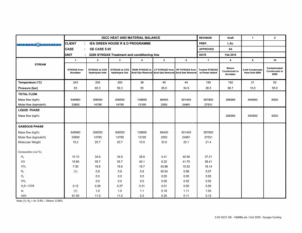
REVISION Draft 1 2IGCC HEAT AND MATERIAL BALANCE REVISION Draft 1 2IGCC HEAT AND MATERIAL BALANCE
CLIENT : IEA GREEN HOUSE R & D PROGRAMME PREP L SoCLIENT : IEA GREEN HOUSE R & D PROGRAMME PREP. L.So.
CASE GE CASE 5 05 APPROVED SACASE : GE CASE 5.05 APPROVED SA
UNIT : 2200 SYNGAS Treatment and conditioning line DATE Feb 2010UNIT : 2200 SYNGAS Treatment and conditioning line DATE Feb 2010
1 2 3 4 5 6 7 8 9 101 2 3 4 5 6 7 8 9 10
STREAMSTREAMReturn ContaminatedSYNGAS from SYNGAS at COS SYNGAS at COS RAW SYNGAS to LP SYNGAS from HP SYNGAS from Treated SYNGAS Return
C d t t Cold Condensate Contaminated C d t tSYNGAS from
ScrubberSYNGAS at COS Hydrolysis Inlet
SYNGAS at COS Hydrolysis Out
RAW SYNGAS to Acid Gas Removal
LP SYNGAS from Acid Gas Removal
HP SYNGAS from Acid Gas Removal
Treated SYNGAS to Power Island Condensate to Cold Condensate
from Unit 4200 Condensate to Scrubber Hydrolysis Inlet Hydrolysis Out Acid Gas Removal Acid Gas Removal Acid Gas Removal to Power Island Scrubber from Unit 4200 SWSScrubber SWS
Temperature (°C) 243 200 200 38 45 44 150 192 21 53 Temperature (°C) 243 200 200 38 45 44 150 192 21 53
P (b ) 63 60 3 59 3 55 26 0 54 9 26 5 66 7 10 0 55 0 Pressure (bar) 63 60.3 59.3 55 26.0 54.9 26.5 66.7 10.0 55.0( )
TOTAL FLOW TOTAL FLOW
Mass flow (kg/h) 648960 306550 306550 138850 86400 501400 587800 366985 594850 6000 Mass flow (kg/h) 648960 306550 306550 138850 86400 501400 587800 366985 594850 6000
Molar flow (kgmole/h) 33800 14785 14785 13195 2550 24981 27531 Molar flow (kgmole/h) 33800 14785 14785 13195 2550 24981 27531
LIQUID PHASE LIQUID PHASE
Mass flow (kg/h) 366985 594850 6000 Mass flow (kg/h) 366985 594850 6000
GASEOUS PHASE GASEOUS PHASE
M fl (k /h) 648960 306550 306550 138850 86400 501400 587800 Mass flow (kg/h) 648960 306550 306550 138850 86400 501400 587800( g )
M l fl (k l /h) 33800 14785 14785 13195 2550 24981 27531 Molar flow (kgmole/h) 33800 14785 14785 13195 2550 24981 27531( g )
M l l W i ht 19 2 20 7 20 7 10 5 33 9 20 1 21 4 Molecular Weight 19.2 20.7 20.7 10.5 33.9 20.1 21.4g
C iti ( l %) Composition (vol %)p ( )
H 15 10 34 6 34 6 38 8 4 41 40 56 37 21 H2 15.10 34.6 34.6 38.8 4.41 40.56 37.212
CO 15 60 35 7 35 7 40 1 6 22 41 70 38 41 CO 15.60 35.7 35.7 40.1 6.22 41.70 38.41CO 7 30 16 6 16 6 18 7 43 88 15 52 18 14 CO2 7.30 16.6 16.6 18.7 43.88 15.52 18.14N (1) 0 8 0 8 0 9 45 04 0 98 5 07 N2 (1) 0.8 0.8 0.9 45.04 0.98 5.07( )O 0 0 0 0 0 0 0 00 0 00 0 00 O2 0.0 0.0 0.0 0.00 0.00 0.00CH 0 0 0 0 0 0 0 00 0 02 0 02 CH4 0.0 0.0 0.0 0.00 0.02 0.02H S + COS 0 12 0 28 0 27 0 31 0 01 0 00 0 00 H2S + COS 0.12 0.28 0.27 0.31 0.01 0.00 0.00A (1) 1 0 1 0 1 1 0 19 1 11 1 03 Ar (1) 1.0 1.0 1.1 0.19 1.11 1.03( )H2O 61 00 11 0 11 0 0 2 0 25 0 11 0 12 H2O 61.00 11.0 11.0 0.2 0.25 0.11 0.12
N t (1) N + A 0 8% Oth 0 08%Note (1): N2 + Ar: 0.8% - Others: 0.08%( ) 2
5.05 IGCC GE - H&MBs.xls / Unit 2200 - Syngas Cooling
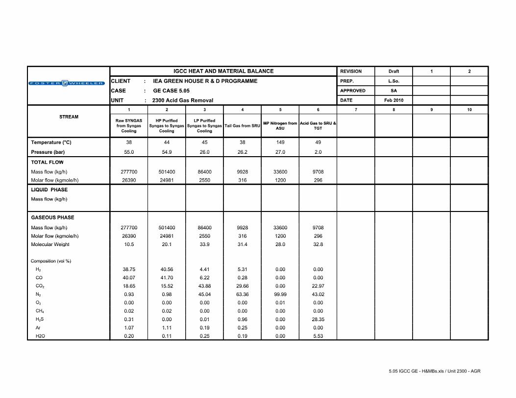
REVISION D ft 1 2IGCC HEAT AND MATERIAL BALANCE REVISION Draft 1 2IGCC HEAT AND MATERIAL BALANCE
CLIENT : IEA GREEN HOUSE R & D PROGRAMME PREP. L.So.CLIENT : IEA GREEN HOUSE R & D PROGRAMME PREP. L.So.
CASE : GE CASE 5 05 APPROVED SACASE : GE CASE 5.05 APPROVED SA
UNIT 2300 A id G R l DATE F b 2010UNIT : 2300 Acid Gas Removal DATE Feb 2010
1 2 3 4 5 6 7 8 9 101 2 3 4 5 6 7 8 9 10
STREAMSTREAMRaw SYNGAS HP Purified LP PurifiedRaw SYNGAS f S
HP Purified S t S
LP Purified S t S T il G f SRU MP Nitrogen from Acid Gas to SRU &from Syngas Syngas to Syngas Syngas to Syngas Tail Gas from SRU MP Nitrogen from
ASUAcid Gas to SRU &
TGTy gCooling
y g y gCooling
y g y gCooling ASU TGTCooling Cooling Cooling
T t (°C) 38 44 45 38 149 49 Temperature (°C) 38 44 45 38 149 49p ( )
Pressure (bar) 55.0 54.9 26.0 26.2 27.0 2.0 Pressure (bar) 55.0 54.9 26.0 26.2 27.0 2.0
TOTAL FLOW TOTAL FLOW
M fl (k /h) 277700 501400 86400 9928 33600 9708 Mass flow (kg/h) 277700 501400 86400 9928 33600 9708( g )
M l fl (k l /h) 26390 24981 2550 316 1200 296 Molar flow (kgmole/h) 26390 24981 2550 316 1200 296( g )
LIQUID PHASE LIQUID PHASE
Mass flow (kg/h) Mass flow (kg/h)
GASEOUS PHASE GASEOUS PHASE
Mass flow (kg/h) 277700 501400 86400 9928 33600 9708 Mass flow (kg/h) 277700 501400 86400 9928 33600 9708
Molar flow (kgmole/h) 26390 24981 2550 316 1200 296 Molar flow (kgmole/h) 26390 24981 2550 316 1200 296
Molecular Weight 10.5 20.1 33.9 31.4 28.0 32.8 Molecular Weight 10.5 20.1 33.9 31.4 28.0 32.8
Composition (vol %) Composition (vol %)
H2 38.75 40.56 4.41 5.31 0.00 0.00 H2 38.75 40.56 4.41 5.31 0.00 0.00 CO 40.07 41.70 6.22 0.28 0.00 0.00 CO 40.07 41.70 6.22 0.28 0.00 0.00 CO2 18.65 15.52 43.88 29.66 0.00 22.97 CO2 18.65 15.52 43.88 29.66 0.00 22.97 N2 0.93 0.98 45.04 63.36 99.99 43.02 N2 0.93 0.98 45.04 63.36 99.99 43.02 O2 0.00 0.00 0.00 0.00 0.01 0.00 O2 0.00 0.00 0.00 0.00 0.01 0.00 CH4 0.02 0.02 0.00 0.00 0.00 0.00 CH4 0.02 0.02 0.00 0.00 0.00 0.00 H2S 0.31 0.00 0.01 0.96 0.00 28.35 H2S 0.31 0.00 0.01 0.96 0.00 28.35 Ar 1.07 1.11 0.19 0.25 0.00 0.00 Ar 1.07 1.11 0.19 0.25 0.00 0.00 H2O 0.20 0.11 0.25 0.19 0.00 5.53 H2O 0.20 0.11 0.25 0.19 0.00 5.53
5.05 IGCC GE - H&MBs.xls / Unit 2300 - AGR

REVISION Draft 1 2IGCC HEAT AND MATERIAL BALANCE REVISION Draft 1 2IGCC HEAT AND MATERIAL BALANCE
CLIENT IEA GREEN HOUSE R & D PROGRAMMECLIENT : IEA GREEN HOUSE R & D PROGRAMME PREP. L.So.CLIENT : IEA GREEN HOUSE R & D PROGRAMME PREP. L.So.
CASE : GE CASE 5 05 APPROVED SACASE : GE CASE 5.05 APPROVED SA
UNIT : 2400 Sulphur Recovery Unit (SRU) & Tail Gas Treatment (TGT) DATE Feb 2010UNIT : 2400 Sulphur Recovery Unit (SRU) & Tail Gas Treatment (TGT) DATE Feb 2010
1 2 3 4 5 6 7 8 9 101 2 3 4 5 6 7 8 9 10
STREAMSTREAM Acid Gas from P d t S l h Off-Gas from Claus Tail Gas toAcid Gas from AGR Unit Product Sulphur Off-Gas from
GasificationClaus Tail Gas to
AGR UnitAGR Unit p Gasification AGR Unit
(°C) Temperature (°C) 49 82.2 38 Temperature ( C) 49 82.2 38
Pressure (bar) 2 0 1 0 26 2 Pressure (bar) 2.0 1.0 26.2
TOTAL FLOW TOTAL FLOW
Mass flow (kg/h) 9708 61.9 t/d 4037 9928 Mass flow (kg/h) 9708 61.9 t/d 4037 9928
Molar flow (kgmole/h) 296 191 316 Molar flow (kgmole/h) 296 191 316
LIQUID PHASE LIQUID PHASE
Mass flow (kg/h) Mass flow (kg/h)
GASEOUS PHASE GASEOUS PHASE GASEOUS PHASE
Mass flow (kg/h) 9708 4037 9928 Mass flow (kg/h) 9708 4037 9928
Molar flow (kgmole/h) 296 191 316 Molar flow (kgmole/h) 296 191 316
Molecular Weight 32 8 21 2 31 4 Molecular Weight 32.8 21.2 31.4
Composition (vol %) Composition (vol %)
H2 0 00 21 15 5 31 H2 0.00 21.15 5.31CO 0 00 28 45 0 28 CO 0.00 28.45 0.28CO2 22 97 13 49 29 66 CO2 22.97 13.49 29.66N2 43 02 0 00 63 36 N2 43.02 0.00 63.36O2 0 00 0 00 0 00 O2 0.00 0.00 0.00CH4 0 00 0 00 0 00 CH4 0.00 0.00 0.00H2S 28 35 1 14 0 96 H2S 28.35 1.14 0.96Ar 0 00 0 00 0 25 Ar 0.00 0.00 0.25H2O 5 53 35 77 0 19 H2O 5.53 35.77 0.19
5.05 IGCC GE - H&MBs.xls / Unit 2400 - SRU & TGT

IGCC HEAT & MATERIAL BALANCECLIENT : IEA GREEN HOUSE R & D PROGRAMME CASE : GE CASE 5.05UNIT : 3000 POWER ISLAND
Stream Description Flowrate Temperature Pressure Entalphyt/h °C bar a kJ/kg
1 Treated SYNGAS from Syngas Cooling (*) (1) 293.85 150 26.5 194.8
2 Extraction Air to Air Separation Unit (*) 285.49 402 14.6 -
3 MP Nitrogen from ASU (*) 363.00 213.00 22.10 -
4 HP Steam to Process Units 5.00 340 85.0 2935.6
5 HP Steam to Steam Turbine (*) 255.68 552 156.5 3447
6 Hot RH Steam to Steam Turbine (*) 311.13 537 36.7 3532
7 MP Steam from Steam Turbine (*) 255.68 344 39.7 3080
8 LMP Steam to Steam Turbine (*) 170.30 350 20.0 3138
9 LP Steam to Steam Turbine (*) 111.82 237 6.2 2930
10 MP Steam to MP -Superheater (*) 55.45 251.8 41.0 2800
11 LP Steam to LP Superheater (*) 111.82 166.8 7.2 2765
12 BFW to VLP Pumps (*) 28.30 119 1.9 499
13 BFW to LP BFW Pumps (*) 170.18 119 1.9 499
14 BFW to MP BFW Pumps (*) 277.83 119 1.9 499
15 BFW to HP BFW Pumps (*) 259.47 119 1.9 499
16 Hot Condensate returned from Unit 2200 (*) 594.85 92 2.5 348
17 Hot Condensate returned from CR (*) 82.25 94 2.5 394
18 Water from Flash Drum (*) 36.55 119 2.5 499
19 FLUE GAS AT STACK (*) (2) 2657.10 129 AMB. 117
20 Condensate from Syngas Final Heater (*) 87.82 118 2.5 495
21 LP Steam Turbine Exhaust 1189.70 21.7 0.026 2220
22 Sea Water Supply to Steam Condenser 85933 12 3.0 50.5
23 Sea Water Return from Steam Condenser 85933 19 2.1 79.8
(*) flowrate for one train(1) Syngas Composition as per stream 7 of Material Balance for Unit 2200(2) Flues gas molar composition: N2: 74.0%; H2O: 6.1%; O2: 10.5%; CO2: 8.5%; Ar: 0.9%.
5.05 IGCC GE - H&MBs.xls / Unit 3000 - Power Island

IEA GHG Water usage and loss of power in plants with CCS
Report #4 - Section B – GEE IGCC without CCS, reference case
Revision no.: Date:
Draft March 2010 Sheet: 23 of 30
6. Utility consumption The Utility Consumptions of the process / utility & offsite units are attached hereafter. Italic font style indicates that the figure in the table has been updated, compared with the analogous figure in reference plant.

IEA GHG Water usage and loss of power in plants with CCS
Report #4 - Section B – GEE IGCC without CCS, reference case
Revision no.: Date:
Draft March 2010 Sheet: 24 of 30

IEA GHG Water usage and loss of power in plants with CCS
Report #4 - Section B – GEE IGCC without CCS, reference case
Revision no.: Date:
Draft March 2010 Sheet: 25 of 30

IEA GHG Water usage and loss of power in plants with CCS
Report #4 - Section B – GEE IGCC without CCS, reference case
Revision no.: Date:
Draft March 2010 Sheet: 26 of 30
7. Overall performance The table summarizing the Overall Performance of the GEE IGCC power plant, case 5.05, is attached hereafter.

IEA GHG Water usage and loss of power in plants with CCS
Report #4 - Section B – GEE IGCC without CCS, reference case
Revision no.: Date:
Draft March 2010 Sheet: 27 of 30
8. Environmental Impact
The GEE IGCC power plant, case 5.05, is designed to process coal, whose characteristic is shown at Section A of present report, and produce electric power. The gaseous emissions, liquid effluents and solid wastes from the power plant are summarized in the present paragraph.
8.1. Gaseous Emissions
8.1.1. Main Emissions In normal operation at full load, the main continuous emissions are the combustion flue gases of the two trains of the Power Island, proceeding from the combustion of the Syngas in the two gas turbines. The following Table 8.1 summarises expected flow rate and concentration of the combustion flue gas from one train of the Power Island.
Table 8.1 – Expected gaseous emissions from one train of the Power Island. Normal Operation Wet gas flow rate, kg/s 738,1 Flow, Nm3/h(1) 3.140.950 Temperature, °C 129
Composition (%vol) Ar 0,95 N2 73,98 O2 10,51
CO2 8,46 H2O 6,10
Emissions mg/Nm3 (1) NOx 51 SOx 10CO 31
Particulate 4 (1) Dry gas, O2 content 15%vol Both the Combined Cycle Units have the same flue gas composition and flow rate. The expected total gaseous emissions of the Power Island are given in Table 8.2

IEA GHG Water usage and loss of power in plants with CCS
Report #4 - Section B – GEE IGCC without CCS, reference case
Revision no.: Date:
Draft March 2010 Sheet: 28 of 30
Table 8.2 – Expected total gaseous emissions of the Power Island.
Normal Operation Wet gas flow rate, kg/s 1476,2 Flow, Nm3/h(1) 6.281.900 Temperature, °C 129
Emissions kg/hNOx 321,4 SOx 60,8 CO 196,0
Particulate 25,8 (1) Dry gas, O2 content 15%vol
8.1.2. Minor Emissions The remainder gaseous emissions within the IGCC Complex are created by process vents and fugitive emissions. Some of the vent points emit continuously; others during process upsets or emergency conditions only. All vent streams containing, potentially, undesirable gaseous components are sent to a flare system. Venting via the flare will be minimal during normal operation, but will be significant during emergencies, process upsets, start up and shutdown. Fugitive emissions are those emissions caused by storage and handling of materials (solids transfer, leakage, etc.). Proper design and operation prevent them.
8.2. Liquid Effluent Most of the effluent from the Waste Water Treatment (Unit 4600) is recovered and recycled back to the gasification island (24.0 t/h water recovered from WWT vs 32.2 t/h total water effluent). The water effluent from WWT, which is not recycled to the gasification island (8.2 t/h), is to be disposed outside Power Plant battery limit. Sea water in open circuit is used for cooling. The return stream Water is treated with meta-bisulphite in the Dechlorination System to reduce the Cl2 concentration. Main characteristics of the water are listed in the following: • Maximum flow rate : 121.000 m3/h • Temperature : 19 °C • Cl2 : <0.05 ppm
IEA GHG Water usage and loss of power in plants with CCS
Report #4 - Section B – GEE IGCC without CCS, reference case
Revision no.: Date:
Draft March 2010 Sheet: 29 of 30
8.3. Solid Effluent The process does not produce any solid waste, except for typical industrial plant waste e.g. (sludge from Waste Water Treatment etc.). In any case, the waste water sludge (expected flow rate: 2 m3/h) can be recovered, recycled back to the Gasification Island and burned into the Gasifier. In addition, the Gasification Island is expected to produce the following solid byproducts:
Fine Slag Flow rate : 29,8 t/h Water content : 70 %wt
Coarse Slag Flow rate : 71,6 t/h Water content : 50 %wt Both slag products can be sold to be commercially used as major components in concrete mixtures to make road, pads, storage bins.

IEA GHG Water usage and loss of power in plants with CCS
Report #4 - Section B – GEE IGCC without CCS, reference case
Revision no.: Date:
Draft March 2010 Sheet: 30 of 30
9. Equipment List
The list of main equipment and process packages is included in this paragraph. In the equipment list, the major water consumers/producers have been highlighted with the relevant water production/consumption.

CLIENT: REVISION Rev.: Draft Rev.1 Rev.2 Rev.3LOCATION: DATE February 2010
PROJ. NAME: ISSUED BY L.So.CONTRACT N. CHECKED BY PC
APPROVED BY SA
motor rating P design T design[kW] [barg] [°C]
Syngas scrubber734 t/h of condensate from unit 2200
Black water flash drum12 t/h sour water from unit 2200
Black water flash drum 1.2 t/h steam in sour gas
Grey water tank89 t/h raw water as make up
Grey water tank24 t/h treated water from WWT
Grey water tank 14.6 t/h water blowdown
Drag conveyor and slag screen 35.8 t/h in coarse slag
Rotatory filter 20.9 t/h in fine slag
Gasification section 5 t/h HP steam condensate is recovered
LEGEND:For the Gasification Unit, only the water consumer items are shown.
Water in Water out
EQUIPMENT LIST Unit 1000 - Gasification Unit - GE Case 5.05 - High Pressure w/o CO2 capture
RemarksTRAIN MaterialsITEM
IEA GREENHOUSE R&D PROGRAMMENetherlandsWater usage and loss of Power in Plants with CCS1- BD- 0475 A
DESCRIPTION TYPE SIZE
Page 1 of 12

CLIENT: REVISION Rev.: Draft Rev.1 Rev.2 Rev.3LOCATION: DATE February 2010
PROJ. NAME: ISSUED BY L.So.CONTRACT N. CHECKED BY PC
APPROVED BY SA
motor rating P design T design[kW] [barg] [°C]
HEAT EXCHANGERS S, m2 shell / tube shell / tube
1 E-2101 Nitrogen heater Shell & Tube 19 / 26 430 / 2432 E-2101 Nitrogen heater Shell & Tube 19 / 26 430 / 243
PACKAGESHP O2 flow rate to Gasifier = 274 t/h
85
MP N2 flow rate to GTs = 890 t/h
26
HMP N2 flow rate to AGR = 36 t/h
34
LP N2 flow rate to Proc Unit = 2.7 t/h
14
Air flow rate from GTs = 603 t/h
ASU Compressors 118.4 MWASU Heat Exchangers
Shell & tube Heat Exchangers
16 services; duty = 11 MWth each; surface = 1000
m2 each
tubes: titaniumshell: CS
ASU chiller 4 MW th @ 5°C
LEGEND:The water consumer equipment is highlighted in the present equipment list.
20.2 t/h steam to internal heaters
20.2 t/h steam condensate to
recovery
SIZETRAIN ITEM DESCRIPTION TYPE Materials
DUTY = 14320 kWDUTY = 14320 kW
IEA GREENHOUSE R&D PROGRAMMENetherlandsWater usage and loss of Power in Plants with CCS1- BD- 0475 A
Nitrogen purity = 99,9 %
EQUIPMENT LIST Unit 2100 - Air Separation Unit - GE Case 5.05 - High Pressure w/o CO2 capture
Remarks Water in Water out
sea water coolers
Air Separation Unit Package (two parallel trains, each sized for 50% of the capacity)
Z-2100 Oxigen purity = 95 %
Nitrogen purity = 98 %
Nitrogen purity = 99,9 %
Page 2 of 12

CLIENT: REVISION Rev.: Draft Rev.1 Rev.2 Rev.3LOCATION: DATE February 2010
PROJ. NAME: ISSUED BY L.So.CONTRACT N. CHECKED BY PC
APPROVED BY SA
motor rating P design T design[kW] [barg] [°C]
HEAT EXCHANGERS S, m2 Shell/tube Shell/tube
1 E-2201 LMP Steam Generator Kettle 24 / 68 250 / 273
2 E-2201 LMP Steam Generator Kettle 24 / 68 250 / 273
1 E-2202 LP Steam Generator Kettle 12 / 68 250 / 250
2 E-2202 LP Steam Generator Kettle 12 / 68 250 / 250
1 E-2203 VLP Steam Generator Kettle 7 / 68 185 / 204
2 E-2203 VLP Steam Generator Kettle 7 / 68 185 / 204
1 E-2206 VLP Steam Generator Kettle 7 / 68 175 / 210
2 E-2206 VLP Steam Generator Kettle 7 / 68 175 / 210
1 E-2204 Syngas Feed/ Product Exchanger Shell & Tube 68 / 68 230 / 185
2 E-2204 Syngas Feed/ Product Exchanger Shell & Tube 68 / 68 230 / 185
1 E-2205 Hydrolysis Feed Heater Shell & Tube 24 +FV / 68 250 / 230
2 E-2205 Hydrolysis Feed Heater Shell & Tube 24 +FV / 68 250 / 230
57.2 t/h VLP BFW
56.6 t/h VLP steam
+ 0.6 t/h blowdown
13 t/h LMP steam
recovered as condensate
DUTY = 3400 kW H2 service H2/Wet H2S serv. on channel DUTY = 3400 kW H2 service H2/Wet H2S serv. on channel
SIZE Materials
DUTY = 2825 kW H2 service H2/Wet H2S serv. on channel
DUTY = 2825 kW H2 service H2/Wet H2S serv. on channel
DUTY = 106350 kW H2 service H2/Wet H2S serv. on channel
DUTY = 78600 kW H2 service H2/Wet H2S serv. on channel DUTY = 14305 kW H2 service H2/Wet H2S serv. on channel DUTY = 14305 kW H2 service H2/Wet H2S serv. on channel
DUTY = 78600 kW H2 service H2/Wet H2S serv. on channel
IEA GREENHOUSE R&D PROGRAMMENetherlandsWater usage and loss of Power in Plants with CCS1- BD- 0475 A
EQUIPMENT LIST Unit 2200 - Syngas Treatment and conditioning line - GE Case 5.05 - High Pressure w/o CO 2 capture
DUTY = 3535 kW H2 service H2/Wet H2S serv. on channel
RemarksTRAIN ITEM DESCRIPTION TYPE
DUTY = 106350 kW H2 service H2/Wet H2S serv. on channel
DUTY = 3535 kW H2 service H2/Wet H2S serv. on channel
Water in Water out
355.8 t/h LMP BFW
352.3 t/h LMP steam
+ 3.5 t/h blowdown
270.3 t/h LP BFW
267.6 t/h LP steam
+ 2.7 t/h blowdown
Page 3 of 12

CLIENT: REVISION Rev.: Draft Rev.1 Rev.2 Rev.3LOCATION: DATE February 2010
PROJ. NAME: ISSUED BY L.So.CONTRACT N. CHECKED BY PC
APPROVED BY SA
motor rating P design T design[kW] [barg] [°C]
SIZE Materials
IEA GREENHOUSE R&D PROGRAMMENetherlandsWater usage and loss of Power in Plants with CCS1- BD- 0475 A
EQUIPMENT LIST Unit 2200 - Syngas Treatment and conditioning line - GE Case 5.05 - High Pressure w/o CO 2 capture
RemarksTRAIN ITEM DESCRIPTION TYPE Water in Water out
HEAT EXCHANGERS (Continued) S, m2 Shell/tube Shell/tube
1 E-2207 A/B Condensate Preheater Shell & Tubeexchanger area =
1700 m2 (exchanger A+B)
26 / 68 100 / 185
2 E-2207 A/B Condensate Preheater Shell & Tubeexchanger area =
1700 m2 (exchanger A+B)
26 / 68 100 / 185
E-2208 Expander Feed Heater Shell & Tube 7 / 68 175 / 140
E-2209 Syngas pre-heater Shell & Tube 7 / 68 175 / 140
E-2210 Syngas heater Shell & Tube 12 / 31 200 / 180 17 t/h LP steam
recovered as condensate
DRUMS D,mm x TT,mm
1 D-2201 Condensate Separator Vertical 68 250 Wet H2S service/H2 service
2 D-2201 Condensate Separator Vertical 68 250 Wet H2S service/H2 service
1 D-2202 Condensate Separator Vertical 68 205 Wet H2S service/H2 service
2 D-2202 Condensate Separator Vertical 68 205 Wet H2S service/H2 service
1 D-2203 Condensate Separator Vertical 68 185
2 D-2203 Condensate Separator Vertical 68 185
1 D-2204 A/B Condensate Separator Vertical 68 185
2 D-2204 A/B Condensate Separator Vertical 68 185
1 D-2205 Condensate Separator Vertical 68 68
2 D-2205 Condensate Separator Vertical 68 68
recovered as condensate
Wet H2S service/H2 service
Equipped with demister Wet H2S service/H2 service
DUTY = 33602 kW H2 service H2/Wet H2S serv. on channel DUTY = 33602 kW H2 service H2/Wet H2S serv. on channel
DUTY = 14770 kW H2 service H2/Wet H2S serv. on channel DUTY = 12820 kW H2 service H2/Wet H2S serv. on channel DUTY = 9870 kW H2 service H2/Wet H2S serv. on channel
Equipped with demister Wet H2S service/H2 service
Equipped with demister Wet H2S service/H2 service
Equipped with demister Wet H2S service/H2 service
Wet H2S service/H2 service
734 t/h return condensate
to Gasification;
12 t/h contaminated condensate
to SWS
46.1 t/h VLP steam
Page 4 of 12

CLIENT: REVISION Rev.: Draft Rev.1 Rev.2 Rev.3LOCATION: DATE February 2010
PROJ. NAME: ISSUED BY L.So.CONTRACT N. CHECKED BY PC
APPROVED BY SA
motor rating P design T design[kW] [barg] [°C]
SIZE Materials
IEA GREENHOUSE R&D PROGRAMMENetherlandsWater usage and loss of Power in Plants with CCS1- BD- 0475 A
EQUIPMENT LIST Unit 2200 - Syngas Treatment and conditioning line - GE Case 5.05 - High Pressure w/o CO 2 capture
RemarksTRAIN ITEM DESCRIPTION TYPE Water in Water out
DRUMS (continued) D,mm x TT,mm
D-2206 Process Condensate Accumulator Horizontal 68 220
PUMPS Q,m3/h x H,m
P-2201 A/B Process condensate pump centrifugal
REACTOR D,mm x TT,mm
1 R-2201 COS Hydrolysis Reactor vertical 68 230
2 R-2201 COS Hydrolysis Reactor vertical 68 230
EXPANDERS
EX- 2201 Purified Syngas Expander centrifugalPout/Pin = 0,50
Flow = 560 kNm3/h Power = 11 MWe
GENERATORS P, MWe
G-3201 Expander Generator
PACKAGE UNITS
Z-2201 Catalyst Loading System
Z-2202 COS Hydrolysis Catalyst
LEGEND:The water consumer equipment is highlighted in the present equipment list.
Catalyst volume: 160 m3
H2 service Wet H2S service
One operating, one spare
H2 service Wet H2S service
0.1 t/h water loss to COS
hydrolisis
Page 5 of 12

CLIENT: REVISION Rev.: Draft Rev.1 Rev.2 Rev.3LOCATION: DATE February 2010
PROJ. NAME: ISSUED BY L.So.CONTRACT N. CHECKED BY PC
APPROVED BY SA
motor rating P design T design[kW] [barg] [°C]
PACKAGESSulphur Prod.=61.9 t/d
Acid Gas from AGR = 300 kmol/h 3.5 80
Off gas from Gasif. = 190 kmol/h
Expected Treated Tail Gas=316 kmol/h 30 70
LEGEND:The water consumer equipment is highlighted in the present equipment list.
Major components (wet basis): CO2 = 29,66%, H2=5,31%, N2 = 63,36%
Z-2400 Sulphur Recovery Unit and Tail Gas Treatment Package (two Sulphur Recovery Unit, each sized for 100% of the capacity and one Tail Gas Treatment Unit sized for 100% of capacity, including Reduction Reactor and Tail Gas Compressor)
Sulphur content = 99,9 wt min (dry basis)
Sulphur content = 28,3% (wet basis)
Sulphur content = 1,1 % (wet basis)
IEA GREENHOUSE R&D PROGRAMMENetherlandsWater usage and loss of Power in Plants with CCS1- BD- 0475 A
EQUIPMENT LIST Unit 2400 - Sulphur Recovery Unit & Tail Gas Treatment - GE Case 5.05 - High Pressure w/o CO2 capture
RemarksTRAIN ITEM DESCRIPTION TYPE SIZE Materials
5.3 t/h BFW to steam
generators+
2.7 t/h water in sour gas and from reaction
2.4 t/h steam to Plant network;2.8 t/h steam condensate to
condensate unit2.7t/h sour water
to WWT; 0.1 t/h blowdown water to WWT
Water in Water out
Page 6 of 12

CLIENT: REVISION Rev.: Draft Rev.1 Rev.2 Rev.3LOCATION: DATE February 2010
PROJ. NAME: ISSUED BY L.So.CONTRACT N. CHECKED BY PC
APPROVED BY SA
motor rating P design T design[kW] [barg] [°C]
HEAT EXCHANGERS S, m2 Shell/tube Shell/tube
1 E-3101 Syngas Final Heater Shell & Tube 70 / 31 280 / 200
2 E-3101 Syngas Final Heater Shell & Tube 70 / 31 280 / 200
DRUMS D,mm x TT,mm
1 D-3101 Syngas Final Separator vertical 68 200 H2 service
2 D-3101 Syngas Final Separator vertical 68 200 H2 service
PACKAGES
1Z-3101
GT-3101 G-3401
Gas Turbine & Generator Package Gas turbine Gas turbine Generator
PG 9351 (FA) 286 MW
2Z-3101
GT-3101 G-3401
Gas Turbine & Generator Package Gas turbine Gas turbine Generator
PG 9351 (FA) 286 MW
LEGEND:The water consumer equipment is highlighted in the present equipment list.
202.6 t/h steam in flue gas to stack
MaterialsTYPE SIZE
Steam in syngas, in air to turbine and generated in combustion
TRAIN
IEA GREENHOUSE R&D PROGRAMMENetherlandsWater usage and loss of Power in Plants with CCS1- BD- 0475 A
ITEM DESCRIPTION Water in Water out
Included in 2-Z- 3101 Included in 2-Z- 3101
Included in 1-Z- 3101 Included in 1-Z- 3101
DUTY=2420 kW Tubes: H2 service
DUTY=2420 kW Tubes: H2 service
EQUIPMENT LIST Unit 3100 - Gas Turbine - GE Case 5.05 - High Pressure w/o CO2 capture
Remarks
Page 7 of 12

CLIENT: REVISION Rev.: Draft Rev.1 Rev.2 Rev.3LOCATION: DATE February 2010
PROJ. NAME: ISSUED BY L.So.CONTRACT N. CHECKED BY PC
APPROVED BY SA
motor rating P design T design[kW] [barg] [°C]
PUMPS Q,m3/h x H,m1 P-3201 A/B LP BFW Pumps centrifugal
2 P-3201 A/B LP BFW Pumps centrifugal1 P-3202 A/B MP BFW Pumps centrifugal2 P-3202 A/B MP BFW Pumps centrifugal1 P-3203 A/B HP BFW Pumps centrifugal
2 P-3203 A/B HP BFW Pumps centrifugal
1 P-3204 A/B VLP BFW Pumps centrifugal
2 P-3204 A/B VLP BFW Pumps centrifugal
DRUMS D,mm x TT,mm1 D-3204 LMP Steam Receiver Drum horizontal 24 250
2 D-3204 LMP Steam Receiver Drum horizontal 24 2501 D-3205 MP Steam Receiver Drum horizontal 44 2602 D-3205 MP Steam Receiver Drum horizontal 44 2601 D-3206 LP Steam Receiver Drum horizontal 12 2502 D-3206 LP Steam Receiver Drum horizontal 12 250
MISCELLANEA D,mm x H,mm1 X-3201 Flue Gas Monitoring System2 X-3201 Flue Gas Monitoring System1 STK-3201 CCU Stack2 STK-3201 CCU Stack1 SL-3201 Stack Silencer2 SL-3201 Stack Silencer1 DS-3201 MP Steam Desuperheater
2 DS-3201 MP Steam Desuperheater
1 DS-3202 HP Steam Desuperheater
2 DS-3202 HP Steam Desuperheater
Included in 1-HRSG-3201
Included in 2-HRSG-3201
One operating, one spare
One operating, one spare
NOx, CO, SO2, particulate, H2O, O2
NOx, CO, SO2, particulate, H2O, O2
One operating, one spare
One operating, one spare
One operating, one spare
Materials
One operating, one spare
One operating, one spare
Included in 1-HRSG-3201
Included in 2-HRSG-3201
ITEM DESCRIPTION TYPE SIZE
IEA GREENHOUSE R&D PROGRAMMENetherlandsWater usage and loss of Power in Plants with CCS1- BD- 0475 A
One operating, one spare
Water in Water out
EQUIPMENT LIST Unit 3200 - Heat Recovery Steam Generator - GE Case 5.05 - High Pressure w/o CO2 capture
RemarksTRAIN
Page 8 of 12

CLIENT: REVISION Rev.: Draft Rev.1 Rev.2 Rev.3LOCATION: DATE February 2010
PROJ. NAME: ISSUED BY L.So.CONTRACT N. CHECKED BY PC
APPROVED BY SA
motor rating P design T design[kW] [barg] [°C]
MaterialsITEM DESCRIPTION TYPE SIZE
IEA GREENHOUSE R&D PROGRAMMENetherlandsWater usage and loss of Power in Plants with CCS1- BD- 0475 A
Water in Water out
EQUIPMENT LIST Unit 3200 - Heat Recovery Steam Generator - GE Case 5.05 - High Pressure w/o CO2 capture
RemarksTRAIN
PACKAGESZ-3201 Fluid Sampling PackageZ-3202 D-3204
P-3204 a/b/c
Phosphate Injection Package Phosphate storage tank Phosphate dosage pumps
Z-3203 D-3205
P-3205 a/b/c
Oxygen Scavanger Injection Package Oxygen scavanger storage tank Oxygen scavanger dosage pumps
Z-3204 D-3206
P-3206 a/b/c
Amines Injection Package Amines Storage tank Amines Dosage pumps
HEAT RECOVERY STEAMGENERATOR
1 HRSG-3201 Heat Recovery Steam Generator
Horizontal, Natural Circulated, 4 Pressure Levels, Simple Recovery, Reheated.
1 D-3201 HP steam Drum Included in 1-HRS-32011 D-3202 MP steam drum Included in 1-HRS-32011 D-3203 LP steam drum Included in 1-HRS-3201
1 D-3204 VLP steam drum with degassing section Included in 1-HRS-3201 0.3 t/h steam vented to atm
1 E-3201 HP Superheater 2nd section Included in 1-HRS-32011 E-3202 MP Reheater 2nd section Included in 1-HRS-32011 E-3203 HP Superheater 1st section Included in 1-HRS-32011 E-3204 MP Reheater 1st section Included in 1-HRS-32011 E-3205 HP Evaporator Included in 1-HRS-32011 E-3206 LMP Superheater Included in 1-HRS-32011 E-3207 HP Economizer 3rd section Included in 1-HRS-32011 E-3208 MP Superheater Included in 1-HRS-32011 E-3209 MP Evaporator Included in 1-HRS-32011 E-3210 LP Superheater Included in 1-HRS-32011 E-3211 MP Economizer 2nd section Included in 1-HRS-32011 E-3212 HP Economizer 2nd section Included in 1-HRS-32011 E-3213 LP Evaporator Included in 1-HRS-32011 E-3214 LP Economizer Included in 1-HRS-32011 E-3215 MP Economizer 1st section Included in 1-HRS-32011 E-3216 HP Economizer 1st section Included in 1-HRS-32011 E-3217 VLP Evaporator Included in 1-HRS-3201
Included in Z - 3203 Included in Z - 3203 One operating , one spare Included in Z - 3204 Included in Z - 3204 One operating , one spare
Included in Z - 3202 Included in Z - 3202 One operating , one spare
1.3 t/h blowdown from Steam
Drums
Page 9 of 12

CLIENT: REVISION Rev.: Draft Rev.1 Rev.2 Rev.3LOCATION: DATE February 2010
PROJ. NAME: ISSUED BY L.So.CONTRACT N. CHECKED BY PC
APPROVED BY SA
motor rating P design T design[kW] [barg] [°C]
MaterialsITEM DESCRIPTION TYPE SIZE
IEA GREENHOUSE R&D PROGRAMMENetherlandsWater usage and loss of Power in Plants with CCS1- BD- 0475 A
Water in Water out
EQUIPMENT LIST Unit 3200 - Heat Recovery Steam Generator - GE Case 5.05 - High Pressure w/o CO2 capture
RemarksTRAIN
HEAT RECOVERY STEAMGENERATOR
2 HRSG-3201 Heat Recovery Steam Generator
Horizontal, Natural Circulated, 4 Pressure Levels, Simple Recovery, Reheated.
2 D-3201 HP steam Drum Included in 2-HRS-32012 D-3202 MP steam drum Included in 2-HRS-32012 D-3203 LP steam drum Included in 2-HRS-3201
2 D-3204 VLP steam drum with degassing section Included in 2-HRS-3201 0.3 t/h steam vented to atm
2 E-3201 HP Superheater 2nd section Included in 2-HRS-32012 E-3202 MP Reheater 2nd section Included in 2-HRS-32012 E-3203 HP Superheater 1st section Included in 2-HRS-32012 E-3204 MP Reheater 1st section Included in 2-HRS-32012 E-3205 HP Evaporator Included in 2-HRS-32012 E-3206 LMP Superheater Included in 2-HRS-32012 E-3207 HP Economizer 3rd section Included in 2-HRS-32012 E-3208 MP Superheater Included in 2-HRS-32012 E-3209 MP Evaporator Included in 2-HRS-32012 E-3210 LP Superheater Included in 2-HRS-32012 E-3211 MP Economizer 2nd section Included in 2-HRS-32012 E-3212 HP Economizer 2nd section Included in 2-HRS-32012 E-3213 LP Evaporator Included in 2-HRS-32012 E-3214 LP Economizer Included in 2-HRS-32012 E-3215 MP Economizer 1st section Included in 2-HRS-32012 E-3216 HP Economizer 1st section Included in 2-HRS-32012 E-3217 VLP Evaporator Included in 2-HRS-3201
LEGEND:The water consumer equipment is highlighted in the present equipment list.
1.3 t/h blowdown from Steam
Drums
Page 10 of 12

CLIENT: REVISION Rev.: Draft Rev.1 Rev.2 Rev.3LOCATION: DATE February 2010
PROJ. NAME: ISSUED BY L.So.CONTRACT N. CHECKED BY PC
APPROVED BY SA
motor rating P design T design[kW] [barg] [°C]
HEAT EXCHANGERS S, m2 shell / tube shell / tube
E-3304 Blow-Down Cooler Shell & Tube 20,2 / 4 52 / 140
DRUMS D,mm x TT,mm
D-3301 Flash Drum vertical 3.5 200D-3302 Continuous Blow-down Drum vertical 3.5 140D-3303 Discontinuous Blow-down Drum vertical 3.5 140
PACKAGES
Z-3301 Steam Turbine & Condenser Package
TB-3301 Steam Turbine 406 MWe grossE-3301A/B Inter/After condenser
E-3302 Gland Condenser
E-3303 Steam Condenser shell & tube 686 MW thtubes: titanium;shell: CS
G-3402 Steam Turbine GeneratorJ-3301 Start-up Ejector
J-3302 A/B Holding Ejector 1st StageJ-3303 A/B Holding Ejector 2nd Stage
P-3301A/B/C Condensate Pumps Centrifugal
SL-3301 Start-up Ejector Silencer
LEGEND:The water consumer equipment is highlighted in the present equipment list.
EQUIPMENT LIST Unit 3300 - Steam Turbine and Blow Down System - GE Case 5.05 - High Pressure w/o CO2 capture
RemarksTRAIN ITEM DESCRIPTION TYPE SIZE Materials
IEA GREENHOUSE R&D PROGRAMMENetherlandsWater usage and loss of Power in Plants with CCS1- BD- 0475 A
DUTY = 910 kW
Included in Z - 3201Sea water heat exchanger
Included in Z - 3201
Included in Z - 3201
Included in Z - 3201
Included in Z - 3201Included in Z - 3201Included in Z - 3201Included in Z - 3201Included in Z - 3201 Two operating, one spare
blowdown from Steam Drums
2.6 t/h water to WWT
Water in Water out
Page 11 of 12

CLIENT: REVISION Rev.: Draft Rev.1 Rev.2 Rev.3LOCATION: DATE February 2010
PROJ. NAME: ISSUED BY L.So.CONTRACT N. CHECKED BY PC
APPROVED BY SA
motor rating P design T design[kW] [barg] [°C]
PACKAGES
1 G-3401 Gas Turbine Generator2 G-3401 Gas Turbine Generator
G-3402 Steam Turbine Generator
Closed loop water cooler shell and tube 93 MW th plates: titaniumframe: SS
Close loop CW pumps centrifugal 6660 m3/h x 30m 992 kWe CSWaste water treatment plantSea water pumps submerged 20000 m3/h x 20m 1400 kWe casing, shaft: SS;
impeller: duplexSeawater chemical injectionSea water inlet/outlet works
LEGEND:The water consumer equipment is highlighted in the present equipment list.
sea water
6 pumps in operation + 1 spare
Included in 1 -Z- 3101
Included in Z- 3301
1 pump in operation + 1 spare
Included in 2 -Z- 3101
MISCELLANEA EQUIPMENT
SIZE Materials
IEA GREENHOUSE R&D PROGRAMMENetherlandsWater usage and loss of Power in Plants with CCS1- BD- 0475 A
Water in Water out
EQUIPMENT LIST Unit 3400 - Electric Power Generation - GE Case 5.05 - High Pressure w/o CO 2 capture
RemarksTRAIN ITEM DESCRIPTION TYPE
Page 12 of 12


IEA GHG Water usage and loss of power in plants with CCS
Report #4 - Section C – GEE IGCC with CCS, reference case
Revision no.: Date:
Draft March 2010 Sheet: 1 of 26
CLIENT : IEA GHG PROJECT NAME : WATER USAGE AND LOSS OF POWER IN PLANTS WITH CO2 CAPTURE DOCUMENT NAME : GEE IGCC WITH CCS, REFERENCE CASE – CASE 5.06 ISSUED BY : L. SOBACCHI CHECKED BY : P. COTONE APPROVED BY : S. ARIENTI
Date Revised Pages Issued by Checked by Approved by
March 2010 Draft L. Sobacchi P. Cotone S. Arienti

IEA GHG Water usage and loss of power in plants with CCS
Report #4 - Section C – GEE IGCC with CCS, reference case
Revision no.: Date:
Draft March 2010 Sheet: 2 of 26
SECTION B
GEE IGCC WITH CCS, REFERENCE CASE
I N D E X
1. Introduction ........................................................................................................................ 3 2. Process Description ............................................................................................................ 5
2.1. Overview .................................................................................................................... 5 2.2. Unit 1000 – Gasification Island .................................................................................. 5 2.3. Unit 2100 – Air Separation unit ................................................................................. 6 2.4. Unit 2200 – Syngas Treatment and Conditioning line ............................................... 6 2.5. Unit 2300 – Acid Gas Removal (AGR)...................................................................... 7 2.6. Unit 2400 – SRU and TGT ......................................................................................... 8 2.7. Unit 2500 – CO2 Compression and Drying ................................................................ 8 2.8. Unit 3000 – Power Island ......................................................................................... 10
3. Block Flow Diagrams and Process Flow Diagrams ......................................................... 15 4. Detailed Water Flow Diagram .......................................................................................... 16 5. Heat and Material Balance ............................................................................................... 17 6. Utility consumption .......................................................................................................... 18 7. Overall performance ......................................................................................................... 21 8. Environmental Impact ...................................................................................................... 23
8.1. Gaseous Emissions ................................................................................................... 23 8.1.1. Main Emissions ................................................................................................ 23 8.1.2. Minor Emissions ............................................................................................... 24
8.2. Liquid Effluent ......................................................................................................... 24 8.3. Solid Effluent ............................................................................................................ 24
9. Equipment List ................................................................................................................. 26
IEA GHG Water usage and loss of power in plants with CCS
Report #4 - Section C – GEE IGCC with CCS, reference case
Revision no.: Date:
Draft March 2010 Sheet: 3 of 26
1. Introduction The present case 5.06 refers to a GEE IGCC power plant, fed with bituminous coal and provided with CO2 capture unit. The IEA GHG study number PH4-19, May 2003, has been taken as a reference for the configuration and performances of the plant here analysed. Plant description, process schemes and performance have been taken directly from reference study report. FWI integrated the reference study with additional information and in particular with the analysis of the water usage and the development of a detailed water flow diagram. The main features of the GEE IGCC plant, case 5.06, are: - High pressure (65 bar g) GEE Gasification (Texaco in reference study); - Coal Water Slurry Feed; - Gasifier Quench Type; - Single stage dirty shift; - Separate removal of H2S and CO2. The separate removal of acid gases, H2S and CO2, is based on the Selexol process. The degree of integration between the Air Separation (ASU) and the Gas Turbines is 50%. Gas Turbine power augmentation and syngas dilution for NOx control are achieved with injection of compressed N2 from ASU to the Gas Turbines. The Sulphur Recovery (SRU) is an O2 assisted Claus Unit, with Tail gas catalytic treatment (SCOT type) and recycle of the treated tail gas to AGR. Reference is made to the attached Block Flow Diagram of the plant. The arrangement of the main process units is: Unit Trains 1000 Gasification 4 x 33 %
2 x 66%
2100 ASU 2 x 50% 2200 Syngas Treatment and Conditioning Line 2 x 50%
Syngas Expansion 1 x 100%
2300 AGR 1 x 100%

IEA GHG Water usage and loss of power in plants with CCS
Report #4 - Section C – GEE IGCC with CCS, reference case
Revision no.: Date:
Draft March 2010 Sheet: 4 of 26
2400 SRU 2 x 100%
TGT 1 x 100%
2500 CO2 Compression and Drying 2 x 50%
3000 Gas Turbine (PG – 9351 - FA) 2 x 50% HRSG 2 x 50% Steam Turbine 1 x 100%

IEA GHG Water usage and loss of power in plants with CCS
Report #4 - Section C – GEE IGCC with CCS, reference case
Revision no.: Date:
Draft March 2010 Sheet: 5 of 26
2. Process Description
2.1. Overview The IEA GHG study number PH4-19, May 2003, has been taken as a reference for the plant description and configuration. This description should be read in conjunction with block flow diagrams and process flow diagrams attached in the following paragraph 3. Case 5.06 is an IGCC power plant, based on GEE gasification technology, fed with bituminous coal and provided with CO2 capture unit. The design is a market based design.
2.2. Unit 1000 – Gasification Island The Gasification Unit employs the GEE Gasification Process to convert feedstock coal into syngas. Facilities are included for scrubbing particulates from the syngas, as well as for removing the coarse and fine slag from the quench and scrubbing water. The Gasification Unit includes the following sections: · Coal Grinding/Slurry Preparation · Gasification · Slag Handling · Black Water Flash · Black Water Filtration The description of the Gasification Unit included in paragraph 2 of Report # 4, section B (case 5.05) is still valid for the present case 5.06 and is to be referred if a more detailed description is required.
IEA GHG Water usage and loss of power in plants with CCS
Report #4 - Section C – GEE IGCC with CCS, reference case
Revision no.: Date:
Draft March 2010 Sheet: 6 of 26
2.3. Unit 2100 – Air Separation unit
The Air Separation Unit is installed to produce oxygen and nitrogen through cryogenic distillation of atmospheric air. The description of the Air Separation Unit included in paragraph 2 of Report # 4, section B (case 5.05) is still valid for the present case 5.06 (with the only exception that in case 5.06 there’s no need for a nitrogen stream to be sent to Unit 2300 – AGR, due to the negative impact of the Nitrogen presence in CO2 stream sent to storage) and is to be referred if a more detailed description is required.
2.4. Unit 2200 – Syngas Treatment and Conditioning line Saturated raw syngas from Unit 1000, at approximately 240°C and 62 bar g enters Unit 2200. The syngas is first heated in E-2201 by the hot shift effluent and then enters the Shift Reactor R-2201, where CO is shifted to H2 and CO2 and COS is converted to H2S. The exothermic shift reaction brings the syngas temperature up to 434°C. A single stage shift, containing sulphur tolerant shift catalyst (dirty shift), is used, being this sufficient to meet the required degree of CO2 removal. The hot shifted syngas is cooled in a series of heat exchangers: E-2201 Shift feed product exchanger E-2202 HP Steam Generator E-2203 MP Steam Generator E-2204 LP Steam Generator E-2205 VLP Steam Generator Process condensate collected in the cooling process of the syngas is accumulated in D-2204 and from there pumped back to the syngas scrubber of Unit 1000. The final cooling step of the syngas takes place in E-2206, preheating cold condensate. The process condensate separated after this step is routed to Unit 4000, Sour Water Stripper, being heavily contaminated, the remaining part is accumulated in D-2204. Up to this point Unit 2200 is split into two parallel lines, each sized for 50% capacity of the total syngas flow because of the size limititation of the exchangers involved. Downstream D-2203 Unit 2200 is a single line for 100% capacity. Cold syngas flows to Unit 2300 and returns to Unit 2200, as clean syngas, after H2S and CO2 removal. Clean syngas is preheated in E-2207 with VLP steam and then reduced in pressure, down to 26 bar (g) in the Expander EX-2201, generating electric energy. Expanded clean syngas is heated in E-2208 with VLP steam and sent to Unit 3000 gas turbines.

IEA GHG Water usage and loss of power in plants with CCS
Report #4 - Section C – GEE IGCC with CCS, reference case
Revision no.: Date:
Draft March 2010 Sheet: 7 of 26
2.5. Unit 2300 – Acid Gas Removal (AGR)
The removal of acid gases, H2S and CO2, where required, is an important step of the IGCC operation. In fact, this unit is not only capital intensive and a large consumer of energy, but also is a key factor for the control of the environmental performance of the IGCC. The right selection of the process and of the solvent used to capture the acid gases is important for the performance of the complex. Several different technologies are commercially available for acid gas removal. They can be grouped in 3 categories. The physical solvents, which capture the acid gas in accordance with the Henry’s law; the chemical solvents, which capture the acid gas with a chemical reaction with the solvent, and the mixed solvents, which display both types of capture, physical and chemical. The first group is obviously favoured by a high partial pressure of the acid gas in the syngas, while the second group is less sensitive to the acid gas partial pressure. In the present case 5.06, this Unit utilises Selexol as acid gas solvent (physical solvent). A single train configuration that enhances the acid gases concentration without using Nitrogen from Air Separation Unit is considered. Unit 2300 is characterised by a high syngas pressure (55 bar g) and an extremely high CO2/H2S ratio (183/1). The interfaces of the process are the following, as shown in the Process Flow Diagram attached to the following paragraph 3: Entering Streams 1. Untreated Gas from Syngas Treatment & Conditioning Line 2. Recycle Gas (Tail Gas) from Sulphur Recovery Unit Exit Streams 3. Treated Gas to Expander 4. CO2 to compression. 5. Acid Gas to Sulphur Recovery Unit 3 4 1 2 5
AGR SELEXOL PROCESS

IEA GHG Water usage and loss of power in plants with CCS
Report #4 - Section C – GEE IGCC with CCS, reference case
Revision no.: Date:
Draft March 2010 Sheet: 8 of 26
The Selexol solvent consumption, to make-up losses, is 120 m3/year. The proposed process matches the process specification with reference to concentration of the treated gas exiting the Unit. In fact, the H2S+COS concentration is 4 ppm. This is due to the integration of CO2 removal with the H2S removal, which makes available a large circulation of the solvent that is cooled down by a refrigerant package (Power consumption = 32% of the overall AGR power requirement) before flowing to the CO2 absorber. The CO2 removal rate is more than 91% as required, allowing to reach an overall CO2 capture of 85% with respect to the carbon entering the IGCC. These excellent performances on both the H2S removal and CO2 capture are achieved with a large power consumption. The acid gas H2S concentration is 19% dry basis, more than suitable to feed the oxygen blown Claus process. Together with CO2 exiting the Unit, the following quantities of other components are sent to the final CO2 destination, after compression: - 262 kmol/h of Hydrogen, corresponding to 1,8% vol and to an overall thermal
power of 17,7 MWt, i.e. more than 5,8 MWe. - A very low quantity of H2S, corresponding to a concentration of about 92 ppmvd.
2.6. Unit 2400 – SRU and TGT This Unit is a Package Unit supplied by specialised Vendors. The Sulphur Recovery Section consists of two trains each sized for a production of 66.8 t/day and normally operating at 50%. The description of the SRU and TGT Unit included in paragraph 2 of Report # 4, section B (case 5.05) is still valid for the present case 5.06 and is to be referred if a more detailed description is required.
2.7. Unit 2500 – CO2 Compression and Drying This Unit is a Package Unit supplied by specialised Vendor.

IEA GHG Water usage and loss of power in plants with CCS
Report #4 - Section C – GEE IGCC with CCS, reference case
Revision no.: Date:
Draft March 2010 Sheet: 9 of 26
CO2 as produced by the AGR section is required to be compressed up to 110 bar g prior to export for sequestration, as per the IEA battery limit definition. CO2 at these conditions is a supercritical fluid. The incoming stream of Unit 2500 flows from Unit 2300, Acid Gas Removal, and is the combination of three different streams delivered at the following pressure levels: • MP stream : 27 barg • LP stream : 10 barg • VLP stream : 0,5 barg All of these streams require treating to remove water and compression. These requirements are matched using the flow scheme described below. The stream at lowest pressure is compressed to intermediate pressure and routed to the molecular sieve drier, together with the stream at intermediate pressure, and the higher pressure stream which has been letdown to intermediate pressure. The letdown duty is available for powergen or turbine duty, but has been used adiabatically to cool the combined drier outlet to reduce the compressor power. The total combined stream at intermediate pressure is then dried in the molecular sieve dryers to remove the water to ensure no free water in CO2 service. The final CO2 moisture content of the product stream is less than 1 ppm. The dryers are provided as 2x50% units, each with 2x100% absorption beds, which are electrically regenerated. Total quantities of water removed are small, and are of sufficient quality for recycle to the steam system after appropriate dissolved gas removal. A buffer drum is provided to smooth the returned water flow from the batch dryers. The main equipment of the Drying Unit are as follows: • Feed Heater • 3 x Absorption Beds • Aftercooler • Water KO Drum • After Filter (cartridge type) • Recycle Blower • Regeneration Heater • Moisture Analyser
The dry gas is cooled against the incoming letdown service and routed to the compressors as 2x50% streams. The study is based on compressor information provided by Nuovo Pignone. The compressor system recommended is of the following type:

IEA GHG Water usage and loss of power in plants with CCS
Report #4 - Section C – GEE IGCC with CCS, reference case
Revision no.: Date:
Draft March 2010 Sheet: 10 of 26
• 2x50% machines (API 617); • Between bearing design (NP 2MCL526 + gearbox + BCL405/A or equivalent); • Auto-transformer with appropriate taps for start-up operation; • 2 casings, 3 stages, dry gas seals; • Speed: 9600 rpm; • intermediate pressure inlet (different depending on cases); • 110 bar g outlet.
It is noted that for the CO2 flow rate required for compression, these machines are currently available on the market. The product stream sent to final storage is composed of CO2 and H2+N2 coabsorbed. The main properties of the stream are as follows: • Product stream : 626 t/h. • Product stream : 110 bar. • Composition : %wt CO2 99,4 N2 0,3 H2 0,1 Others 0,2 TOTAL 100,0
2.8. Unit 3000 – Power Island The Process Flow Diagram of this Unit is attached to the following paragraph 3. The power island is based on two General Electric gas turbines, frame 9351 FA, two Heat Recovery Steam Generators (HRSG), generating steam at 3 levels of pressure, and one steam turbine common to the two HRSGs. For the configuration of the present case 5.06 the integration between the Process Units and the Power Island consists of the following interfaces: · Compressed Air : air extracted from the Gat Turbine is delivered
to the Air Separation Unit; · Dilution nitrogen : excess nitrogen from ASU is delivered to GT
for NOx control and power augmentation; · HP steam (160 barg) : steam imported from Syngas Treatment and
Conditioning Line.

IEA GHG Water usage and loss of power in plants with CCS
Report #4 - Section C – GEE IGCC with CCS, reference case
Revision no.: Date:
Draft March 2010 Sheet: 11 of 26
· HP steam (85 barg) : steam exported to the Gasification Island
users. · MP steam (40 barg) : steam imported from Syngas Treatment and
Conditioning Line. A small quantity is also generated in the Sulphur Recovery Unit.
· LP steam (6,5 barg) : steam imported from Syngas Treatment and Conditioning Line. A small quantity is also generated in the Sulphur Recovery Unit.
· VLP steam (3,2 barg) : steam imported from Syngas Treatment and Conditioning Line.
· BFW : HP, MP, LP, VLP Boiler Feed Water is exported to the Process Units to generate the above mentioned steam production.
· Process Condensate : All the condensate recovered from the condensation of the steam utilised in the Process Unit is recycled back to the HRSG after polishing in Unit 4200, Demi Water/Condensate Recovery.
· Condensate from ST : All the Condensate from the Condenser is exported to the polishing unit (Unit 4200), pre-heated in the Syngas Cooling and Conditioning Line and recycled back to the HRSG.
During normal operation, the clean syngas, coming from Unit 2200 – Syngas Treatment and Conditioning Line, is heated up to 170°C against MP BFW in the syngas final heater 1/2-E-3101 dedicated to each Gas Turbine. Before entering each machine the hot syngas goes through dedicated final separator 1/2-D-3101 in order to protect the Gas Turbine from liquid entrainment, mainly during cold start-up. Finally, the hot syngas is burnt inside the Gas Turbine to produce electric power; the resulting stream of hot exhaust gas is conveyed to the Heat Recovery Steam Generator located downstream each Gas Turbine. Compressed air is extracted from the Gas Turbines and delivered to ASU (refer to paragraph 2.3) MP nitrogen coming from ASU is injected into the Gas Turbines for NOx abatement and power output augmentation. The flue gas stream at a temperature of about 600°C flows through the following coils sequence inside the HRSG: · HP Superheater (2nd section); · MP Reheater (2nd section); · HP Superheater (1st section);

IEA GHG Water usage and loss of power in plants with CCS
Report #4 - Section C – GEE IGCC with CCS, reference case
Revision no.: Date:
Draft March 2010 Sheet: 12 of 26
· MP reheater (1st section); · HP Evaporator; · HP Economizer (3rd section); · MP Superheater · MP Evaporator; · LP Superheater; · HP Economizer (2nd section)/MP Economizer (2nd section) (in parallel); · LP Evaporator; · HP economizer (1st section)/MP Economizer (1st section)/LP Econ. (in parallel); · VLP Evaporator. The flue gas is cooled down to about 129°C and then discharged to the atmosphere with stream coming from the other HRSG through a common stack. The condensate stream, extracted from the Steam Condenser E-3303 by means of Condensate Pumps P-3301 A/B/C, is sent as Cold Condensate to the Polishing Unit, located in Unit 4200 – DM Water / Condensate Recovery System. Demineralized water makeup is mixed to the polished stream and finally is sent to the IGCC Process Units where it is heated up by recovering the low temperature heat available. The Hot Condensate coming back from IGCC process units enters the VLP steam drum which is equipped with the degassing tower operating at a temperature of 120°C. Degassed Boiler Feed Water for HP, MP, LP and VLP services is directly taken from deaerator and delivered to the relevant sections by means of dedicated pumps. HP BFW from deaerator is delivered to the HP economizer coils by means of the HP BFW pumps 1/2-P-3203 A/B (two pumps for each HRSG with one pump in operation and one in hot stand-by), flows through the HP Economizer coils and feeds the HP Steam Drum. From the outlet of the 1st section of the HP Economizer coils a portion of hot water is exported at a temperature level of about 160 °C to the IGCC Process Units as HP BFW. The largest portion of the generated steam is superheated in the HP Superheater coils and sent to the HP module of the common Steam Turbine together with HP Superheated steam coming from the second HRSG. The saturated HP Steam bypassing the HP Superheater coils is letdown and mixed with a portion of the HP Superheated Steam to achieve the characteristics required by the HP Steam Users of the IGCC. To control the maximum value of the HP Superheated Steam final temperature, a desuperheating station, located between HP Superheater coils, is provided. Cooling medium is HP BFW taken on the HP BFW pumps discharge and adjusted through a dedicated temperature control valve.

IEA GHG Water usage and loss of power in plants with CCS
Report #4 - Section C – GEE IGCC with CCS, reference case
Revision no.: Date:
Draft March 2010 Sheet: 13 of 26
The exhaust steam from the HP module of the Steam turbine is split between the two HRSGs. Each stream feeds an MP header, and it is mixed with the MP Superheated steam coming from the relevant HRSG section. MP BFW from deaerator is delivered to the MP Economizer coils of each HRSG by means of the MP BFW Pumps 1/2-P-3202 A/B (one operating and one in standby), flows through the MP Economizer coils and feeds the MP Steam Drum. From the outlet of the 1st section of the MP Economizer coils a portion of hot water is exported at a temperature level of about 160 °C to the IGCC Process Units as MP BFW. Generated MP steam is partially diverted to the IGCC Process Units, while the remaining portion is superheated in the MP Superheater coil and mixed to the exhaust steam coming from the HP Module of the common Steam Turbine. The resulting stream is fed to the Reheater coils and the Reheated Steam is delivered to the MP module of the Steam Turbine together with the Reheated Steam coming from the second HRSG. To control the Reheated steam final temperature, a desuperheating station, located between Reheater coils, is provided. Cooling medium is MP BFW taken on the MP BFW pumps discharge and adjusted through a dedicated temperature control valve. The exhaust steam coming from the MP Module of the common Steam Turbine is mixed to the LP Superheated Steam and delivered to the LP Module of the Steam Turbine. LP BFW from deaerator is delivered to the LP Economizer coil by means of two LP BFW Pumps 1/2-P-3201 A/B (one operating and one in stand-by), flows through the LP Economizer coil and feeds the LP Steam Drum. Before entering the LP Steam Drum, a portion of hot water is exported at a temperature level of about 120°C to the IGCC Process Units as LP BFW. Most of the produced steam returns to the Power Island as saturated steam through the LP Steam distribution network. The wet steam at the outlet of the LP module of the Steam Turbine is routed to the steam condenser. The cooling medium in the tube side of the surface condenser is seawater in once through circuit. Continuous HP, MP and LP blowdown flowrates from HRSGs are manually adjusted by means of dedicated angle valves; they are sent to the dedicated blowdown drum together with the possible overflows coming from HRSGs Steam Drums. After flashing, recovered VLP steam is fed to the VLP steam drum while the remaining liquid is cooled down against cold condensate by means a dedicated Blowdown Cooler and delivered to the atmospheric blowdown drum.

IEA GHG Water usage and loss of power in plants with CCS
Report #4 - Section C – GEE IGCC with CCS, reference case
Revision no.: Date:
Draft March 2010 Sheet: 14 of 26
Intermittent HP, MP and LP blowdown flowrates from HRSGs are manually adjusted by means of dedicated angle valves and sent to the dedicated atmospheric blow-down drum. In case of Steam Turbine trip, live HP Steam is bypassed to MP manifold by means of dedicated letdown stations, while Reheated Steam and excess of LP steam are also let down and then sent directly into the condenser neck. When the clean syngas production is not sufficient to satisfy the appetite of both Gas Turbines it is possible to cofire natural gas or to switch to natural gas one or both Gas Turbines. This could happen in case of partial or total failure of the Gasification/Gas Treatment units of the IGCC and during start-up.

IEA GHG Water usage and loss of power in plants with CCS
Report #4 - Section C – GEE IGCC with CCS, reference case
Revision no.: Date:
Draft March 2010 Sheet: 15 of 26
3. Block Flow Diagrams and Process Flow Diagrams The Block Flow Diagram of the GEE IGCC, Case 5.06, and the schematic Flow
Diagrams of Units 2100, 2200, 2300 and 3000 are attached hereafter. The IEA GHG study number PH4/19, May 2003, has been taken as reference for the
plant Block Flow Diagrams and Process Flow Diagrams attached.

GEE CASE 5.06 – IGCC COMPLEX BLOCK FLOW DIAGRAM
GASIFICATION ISLAND (Unit 1000)
SYNGAS TREAT. (Shift Reaction) & CONDITIONING
LINE (Unit 2200 1/2)
AGR (H2S & CO2
removal) (Unit 2300)
ASU
(Unit 2100)
POWER ISLAND
(Unit 3000)
WASTE WATER TREATMENT
(Unit 4600)
SRU & TAIL GAS TREATMENT
(Unit 2400)
HP O2
FILTER CAKE
COAL
COARSE SLAG
WET SYNGAS
CONDENSATE SOUR GAS
ACID GAS TAIL GAS
CLEAN SYNGAS
MP N2
GREY WATER BLOWDOWN TREATED
WATER
AIR INT.
CO2 COMPRESSION
& DRYING (Unit 2500)
SULPHUR LIQUID EFF.
CO2 TO STORAGE
SYNGAS TREAT. (Expander) &
CONDITIONING LINE (Unit 2200 2/2)
AIR

lsobacchi
Case 5.06 - GE IGCC with CCS

lsobacchi
Case 5.06 - GE IGCC with CCS

lsobacchi
Case 5.06 - GE IGCC with CCS

lsobacchi
Case 5.06 - GE IGCC with CCS

lsobacchi
Case 5.06 - GE IGCC with CCS

IEA GHG Water usage and loss of power in plants with CCS
Report #4 - Section C – GEE IGCC with CCS, reference case
Revision no.: Date:
Draft March 2010 Sheet: 16 of 26
4. Detailed Water Flow Diagram
In the present paragraph the following documents are attached: - detailed water Flow Diagram relevant to the entire power plant; - water balance around the major units.

[21 5] [0 6]
CASE 5.06 - GEE IGCC COMPLEX, BITUMINOUS COAL, WITH CO2 CAPTURE (NET POWER OUTPUT = 730.3 MWe) - BLOCK FLOW DIAGRAM - WATER BALANCE
LP STEAM15
DEAERATOR VENT4
TOTAL RAW WATER RAW WATER TO GASIFICATION
IEA GHG R&D PROGRAMME
Water Usage and Loss of Power in Plants with CCS
Task #3
Revision no.:
Date:Sheet:
Draft
March 2010
DEAERATOR VENT
[21.5] [0.6]
[300.3][4.8] [376.1] [394.9]
[18.3]
[5.2] [0.4]
[30.7][21.5]
[5.1]
[0.1][183.4] [12.0]
[59.5]
[597.8] [51.8]
BITUMINOUSCOAL
CONDENSATE TO SCRUBBER
GASIFICATION ISLAND
GAS TURBINEunit 3000
HRSGunit 3000
ASUUnit 2100 .
MP N2STEAM TURBINEunit 3000
FLUE GAS
BLOWDOWNTO WWT
PURIFIED SYNGAS
H2 COMBUSTION
1
28
24
34
GREY WATER TO GRINDING
AIR INTAKE
VENT FROM ASU 37
LP STEAM
LP CONDENSATE
15
7
CONDENSERunit 3000
14
DEAERATOR VENT4
CWS CWR
NET BFW/STEAM
52STEAM TO U&O
NET BFW/STEAM TO UNIT 2200
51
MP STEAM 54
HPS TO GASIFICATIONHP STEAM6
AIR INTAKE FROM GT 35
TOTAL RAW WATER RAW WATER TO GASIFICATION
RAW WATER TO UNIT 4200
SYNGAS PREHEATING
IEA GHG R&D PROGRAMME
Water Usage and Loss of Power in Plants with CCS
Task #3
Revision no.:
Date:Sheet:
Draft
March 2010
33
35
DEAERATOR VENT
WATER LOSSIN SHIFT
61
36
[3.1] [1.2][794.3]
[1.0]
[0.6][12.0] [0.1]
[0.8][0.1] [12.0]
[1.3][7.7]
[72.4][283.0] [0.5] [11.7]
[3.0][51.8]
[0.8][3.3] [1376.1]
[1.0]
GASIFICATION
BLACK WATER FLASH
WET SCRUBBING
BLACK WATER FILTRATION
BITUMINOUSCOAL
SYNGAS COS HYDROLISIS / SHIFT / COOLINGunit 2200
WATER LOSS IN COS HYDROLYSIS
CONDENSATE TO SCRUBBER
GASIFICATION ISLAND
ACID GAS REMOVALunit 2300
GAS TURBINEunit 3000
HRSGunit 3000
ASUUnit 2100 .
MP N2
SRUunit 2400
TGTUunit 2400
STEAM TURBINEunit 3000
FLUE GAS
CONDENSATE RECOVERY /DEMI WATER
WET SYNGAS
SLAG HANDLING
COAL GRINDING /SLURRY PREP
BLOWDOWN FROM HRSG
BLOWDOWNTO WWT
BLOWDOWN FROM STEAM GEN
BLOWDOWN FROM AGR
GAS TOSRU
RAW SYNGAS
PURIFIED SYNGAS
H2 COMBUSTION
1
28
9
14
18
24
32
34
BLACK WATER
COAL SLURRY
BLACK WATERSLAG
WATER
GREY WATER TO GRINDING
HEATED GREY WATER
OFFGASTO SRU / TGTU
MAKE UP WATER
1
22
27
SOUR WATER28
H2S COMBUSTION
BLOWDOWN FROM STEAM GENERATION23
AIR INTAKE
VENT FROM ASU 37
LP STEAM
LP CONDENSATE
15
7
CONDENSERunit 3000
14
DEAERATOR VENT4
CWS CWR
NET BFW/STEAM TO/FROM UNIT 2400
COND FROMUNIT 2400
48
52STEAM TO U&O
COND FROMU&O
44
NET BFW/STEAM TO UNIT 2200
51
49 CONDENSATE FROM SYNGAS PREHEATING
STEAM COND
MP STEAM 54
47
HPS TO GASIFICATIONHP STEAM6
31
CLEAN CONDENSATE
AIR INTAKE FROM GT 35
56
TOTAL RAW WATER RAW WATER TO GASIFICATION
RAW WATER TO UNIT 4200
58
DEMI WATER M.U.
60
SYNGAS PREHEATING
IEA GHG R&D PROGRAMME
Water Usage and Loss of Power in Plants with CCS
Task #3
Revision no.:
Date:Sheet:
Draft
March 2010
33
35
DEAERATOR VENT
53
22
60
29
1
57
WATER LOSSIN SHIFT
61
CO2 COMPRESSION & DRYINGunit 250063
WATER FROM CO2 COMPRESSION
65
TG RECYCLE(negligible)
36
[1.0][1210.3]
[21.7][5.1]
[3.1][4.0]
[38.2] [22.2] [1.6] [17.3]
[15.5][3.0]
[13.9] [0.0][ xxx ] = water flowrates in ton/h
GASIFICATION
BLACK WATER FLASH
WET SCRUBBING
BLACK WATER FILTRATION
BITUMINOUSCOAL
COARSE SLAG
SYNGAS COS HYDROLISIS / SHIFT / COOLINGunit 2200
WATER LOSS IN COS HYDROLYSIS
CONDENSATE TO SCRUBBER
GASIFICATION ISLAND
ACID GAS REMOVALunit 2300
GAS TURBINEunit 3000
HRSGunit 3000
ASUUnit 2100 .
MP N2
SRUunit 2400
TGTUunit 2400
STEAM TURBINEunit 3000
FLUE GAS
CONDENSATE RECOVERY /DEMI-WATERunit 4200
WASTE WATER TREATMENTunit 4600
STEAM CONDENSATE
BLOWDOWN RAW WATER
WET SYNGAS
SLAG HANDLING
COAL GRINDING /SLURRY PREP
SW FROM SRU
BLOWDOWN FROM HRSG
BLOWDOWNTO WWT
BLOWDOWN FROM STEAM GEN
BLOWDOWN FROM AGR
GAS TOSRU
RAW SYNGAS
PURIFIED SYNGAS
H2 COMBUSTION
WATER EFFLUENT
TREATED WATER
1
2
3
5
8
9
13
14
16
17
18
25
24
10
32
34
BLACK WATER
GREY WATER BLOWDOWN
FILTER CAKE
1
COAL SLURRY
BLACK WATERSLAG
WATER
GREY WATER TO GRINDING
HEATED GREY WATER
OFFGASTO SRU / TGTU
MAKE UP WATER
1
22
27
SOUR WATER28
H2S COMBUSTION
BLOWDOWN FROM STEAM GENERATION23
AIR INTAKE
VENT FROM ASU 37
LP STEAM
LP CONDENSATE
15
7
CONDENSERunit 3000
14
DEAERATOR VENT4
CWS CWR
NET BFW/STEAM TO/FROM UNIT 2400
COND FROMUNIT 2400
48
52STEAM TO U&O
COND FROMU&O
44
NET BFW/STEAM TO UNIT 2200
51
49 CONDENSATE FROM SYNGAS PREHEATING
STEAM COND
MP STEAM 54
47
HPS TO GASIFICATIONHP STEAM6
HP STEAM COND42
31
TO OTHER UNITS
50
TO CHEMICALS
43BLOWDOWN FROM OTHER UNITS
CLEAN CONDENSATE
AIR INTAKE FROM GT 35
DEMI WATER M.U.TO AGR
56
TOTAL RAW WATER RAW WATER TO GASIFICATION
RAW WATER TO UNIT 4200
19
58
DEMI WATER M.U.
60
SYNGAS PREHEATING
IEA GHG R&D PROGRAMME
Water Usage and Loss of Power in Plants with CCS
Task #3
Revision no.:
Date:Sheet:
Draft
March 2010
33
35
DEAERATOR VENT
53
22
60
29
1
57
WATER LOSSIN SHIFT
61
CO2 COMPRESSION & DRYINGunit 250063
WATER FROM CO2 COMPRESSION
CO2 TO STORAGE64
65
TG RECYCLE(negligible)
36
12/03/2010 page 1 of 2 IEA - task 03 - detailed balances.xls/case 5.06 - GE IGCC

IEA GHG R&D PROGRAMME
Water Usage and Loss of Power in Plants with CCS
Task #3
Revision no.:
Date:Sheet:
Draft
March 2010
No Flow (ton/h) No Flow (ton/h) No Flow (ton/h) No Flow (ton/h)1 30.7 5 38.2 1 30.7 11 22.22 376.1 4 0.6 28 12.0 5 38.23 17.3 11 22.2 24 597.8 27 794.336 5.2 8 394.9 22 283.0 12 1.329 1.2 9 0.1 25 21.7 13 15.535 18.3 10 13.9 6 5.1 42 5.122 283.0 37 4.8
GEE IGCC fed by bituminous coal, with CO2 capture - Overall Water Balance GEE IGCC fed by bituminous coal, with CO2 capture - Water Balance around Gasification IslandWater In Water Out
Moisture in coalSyngas combustion of H2 in GT
Water In Water OutLocation
SlagRaw water to Demi Plant
SlagDeaerator ventFilter cake
Location Location
Moisture in air to ASU
Raw Water make up to Gasific.Water effluent from WWTMoisture from ASU vent
Water loss in COS hydrolysisFlue gas from GT
H2S combustion in SRUMoisture in combustion air to GT
Make up to Grey Water Tank Sour GasTreated water from WWT Grey Water BlowdownHP steam HP condensate
Condensate to Wet Scrubber Wet syngas
Moisture in coal Filter cakeSour Water to Stripping
Location
61 183.4delta (note 1) delta (note 1)
Total 731.8 Total 658.1 73.7 Total 950.3 Total 876.6 73.7
No Flow (ton/h) No Flow (ton/h) No Flow (ton/h) No Flow (ton/h)13 15.5 25 21.7 3 17.3 32 1376.114 3.3 10 13.9 31 1210.3 19 1.643 3.0 44 12.0 50 4.016 0.5 6 Condensate from Gasification 5.1 60 Demi water make up 11.717 3.1 7 21.518 0.1 47 72.419 1.6 48 3.023 7.7 49 51.863 0.8
Total 35.6 Total 35.6 Total 1393.4 Total 1393.4
Condensate from unit 2300Condensate from unit 2400Blowdown from Demi Plant
Blowdown from unit 2200Water from CO2 compressor
Condensate from syngas preheating
GEE IGCC fed by bituminous coal, with CO2 capture - Water Balance around WWT (unit 4600)Water In Water Out
Blowdown from SRU
Blowdown from HRSG Water effluent from WWT
Blowdown from AGR
pWater loss in shift reaction in unit 2200
Blowdown to WWT
Location Location
Condensate from Steam TurbineTreated water to Gasifier
Condensate from unit 2100
Demi water to chemicalsCondensate from U&O
Sour water from SRU
Blowdown from other units
Grey Water BlowdownLocation Location
Raw Water Demi Water to HRSG and PRS un
GEE IGCC fed by bituminous coal, with CO2 capture - Water Balance around Cond Recovery/Demi Water PlantWater In Water Out
No Flow (ton/h) No Flow (ton/h) No Flow (ton/h) No Flow (ton/h)35 18.3 8 394.9 35 18.3 8 394.92 376.1 6 5.1 2 376.133 0.1 52 12.0 33 0.134 0.4 51 59.5 34 0.432 Clean condensate to HRSG 1376.1 54 72.460 Demi water make up 11.7 53 3.1 Total 394.9 Total 394.9
14 3.315 LP steam to N2 saturator HE 21.531 Steam condensate from CCU 1210.34 Deaerator vent 0.6
No Flow (ton/h) No Flow (ton/h)Total 1782.7 Total 1782.7 27 794.3 9 0.1
51 59.5 24 597.828 12.061 183.457 1.0
No Flow (ton/h) No Flow (ton/h) 23 Blowdown from Steam Gen 7 7
Condensate to scrubber
GEE IGCC fed by bituminous coal, with CO2 capture - Water Balance around Unit 2200
GEE IGCC fed by bituminous coal, with CO2 capture - Water Balance around AGRWater In Water Out
Location Location
Water In Water Out
Moisture in MP nitrogen from ASU Net BFW/LMP steam to unit 2200MP steam to unit 2300Net BFW/Steam to unit 2400Blowdown from HRSG
Location
Syngas combustion of H2 in GT HP steam to GasificationWater in syngas Steam to U&O
Location LocationMoisture in combustion air to GT Flue gas from GT
GEE IGCC fed by bituminous coal, with CO2 capture - Water Balance around Power IslandWater In Water Out
GEE IGCC fed by bituminous coal, with CO2 capture - Water Balance around GT - HRSGWater In Water Out
Location Location
Water in syngasMoisture in MP nitrogen from ASU
Moisture in combustion air to GT Flue gas from GTSyngas combustion of H2 in GT
LocationWet Syngas Water loss in COS hydrolysis
Raw syngas to AGR
Net BFW/steam to unit 2200
Water loss in shift reaction in unit sour water to SWS
No Flow (ton/h) No Flow (ton/h) 23 Blowdown from Steam Gen 7.757 1.0 58 0.6 49 Condensate from syn. preheat. 51.856 1.0 33 0.1 Total 853.8 Total 853.854 72.4 47 72.4
16 0.565 0.8
Total 74.3 Total 74.3
NOTE 1: Water balances around gasification island and around the entire Power Plant don't close to zero by the same amount. The difference between the streams of "water in" and "water out" is due to the shift reactions, occuring in the gasification island.
CO2 to compression
MP steam Steam condensateBlowdown from AGR
Raw Syngas Gas to SRUDemiwater make up Purified syngas
Location Location
12/03/2010 page 2 of 2 IEA - task 03 - detailed balances.xls/case 5.06 - GE IGCC

IEA GHG Water usage and loss of power in plants with CCS
Report #4 - Section C – GEE IGCC with CCS, reference case
Revision no.: Date:
Draft March 2010 Sheet: 17 of 26
5. Heat and Material Balance
The Heat and Material Balance, referring to the Flow Diagrams attached in the previous paragraph 3, is attached hereafter.
The IEA GHG study number PH4/19, May 2003, has been taken as reference for the plant H&M balance attached.

REVISION Draft 1 2IGCC HEAT AND MATERIAL BALANCE REVISION Draft 1 2IGCC HEAT AND MATERIAL BALANCE
CLIENT : IEA GREEN HOUSE R & D PROGRAMME PREP L SoCLIENT : IEA GREEN HOUSE R & D PROGRAMME PREP. L.So.
CASE GEE IGCC CASE 5 06CASE : GEE IGCC CASE 5.06 APPROVED SACASE : GEE IGCC CASE 5.06 APPROVED SA
UNIT : 2100 AIR SEPARATION UNIT DATE March 2010UNIT : 2100 AIR SEPARATION UNIT DATE March 2010
1 2 3 4 5 6 7 81 2 3 4 5 6 7 8
STREAMSTREAMHP OXYGEN to MP NITROGEN t Ai I t k f MP NITROGEN f TOTAL Ai fHP OXYGEN to NOT USED MP NITROGEN to Air Intake from MP NITROGEN for Air from each GT TOTAL Air from TOTAL Air to ASUGasification NOT USED each GT Atmosphere Syngas Dilution Air from each GT GTs TOTAL Air to ASUGasification p y g
Temperature (°C) 148.9 212.7 AMB. 209 400 209 Temperature ( C) 148.9 212.7 AMB. 209 400 209
Pressure (bar) 79 8 21 6 AMB 28 0 14 4 13 9 Pressure (bar) 79.8 21.6 AMB. 28.0 14.4 13.9
TOTAL FLOW TOTAL FLOW
Mass flow (kg/h) 278700 325206 613137 246834 306569 613137 1226274 Mass flow (kg/h) 278700 325206 613137 246834 306569 613137 1226274
Molar flow (kgmole/h) 8650 11581 21236 8814 10618 21236 42471 Molar flow (kgmole/h) 8650 11581 21236 8814 10618 21236 42471
LIQUID PHASE LIQUID PHASE
M fl (k /h) Mass flow (kg/h) Mass flow (kg/h)
GASEOUS PHASE GASEOUS PHASE
M fl (k /h) 278700 325206 613137 246834 306568 5 613137 1226274 Mass flow (kg/h) 278700 325206 613137 246834 306568.5 613137 1226274( g )
M l fl (k l /h) 8650 11581 21236 8814 10618 21236 42471 Molar flow (kgmole/h) 8650 11581 21236 8814 10618 21236 42471( g )
M l l W i ht 32 22 28 00 28 87 28 00 28 87 28 87 28 87 Molecular Weight 32.22 28.00 28.87 28.00 28.87 28.87 28.87o ecu a e g t 3 8 00 8 8 8 00 8 8 8 8 8 8
C i i ( l %) Composition (vol %)Co pos o ( o %)
H H22
CO CO
CO CO22
N N2 1.50 97.50 77.57 97.50 77.57 77.57 77.572 1.50 97.50 77.57 97.50 77.57 77.57 77.57O O2 95.00 2.15 20.86 2.15 20.86 20.86 20.86 O2 95.00 2.15 20.86 2.15 20.86 20.86 20.86
CH4 CH4
H2S + COS H2S COS
Ar 3.50 0.26 0.89 0.26 0.89 0.89 0.89 Ar 3.50 0.26 0.89 0.26 0.89 0.89 0.89 H2O 0.09 0.68 0.09 0.68 0.68 0.68 H2O 0.09 0.68 0.09 0.68 0.68 0.68

REVISION D f 1 2IGCC HEAT AND MATERIAL BALANCE REVISION Draft 1 2IGCC HEAT AND MATERIAL BALANCEIGCC HEAT AND MATERIAL BALANCE
CLIENT : IEA GREEN HOUSE R & D PROGRAMME PREP. L.So.CLIENT : IEA GREEN HOUSE R & D PROGRAMME PREP. L.So.
CASE : GEE IGCC CASE 5 06 APPROVED SACASE : GEE IGCC CASE 5.06 APPROVED SA
UNIT 2200 S t t t d diti i li DATE M h 2010UNIT : 2200 Syngas treatment and conditioning line DATE March 2010y g g1 2 3 4 5 6 7 81 2 3 4 5 6 7 8
STREAMSTREAMSYNGAS t HP P ifi d R t C t i t dSYNGAS at SYNGAS at Shift RAW SYNGAS to HP Purified Treated SYNGAS Return Contaminated Cold CondensateScrubber Outlet to SYNGAS at Shift
Reactor OutletRAW SYNGAS to
Acid Gas Removal SYNGAS from Treated SYNGAS to Power Island Condensate to Condensate to Cold Condensate
from Unit 4200Shift Reactor Reactor Outlet(2 T i )
Acid Gas Removal(2 T i ) Acid Gas Removal to Power Island
(T t l) Gasification Stripping from Unit 4200(2 T i )Shift Reactor
(2 Trains) (2 Trains) (2 Trains) Acid Gas Removal (Total) (Total) Gasification
(2 Trains)Stripping(2 Trains) (2 Trains)(2 Trains) (Total) (2 Trains) (2 Trains)
Temperature (°C) 243 434 38 30 135 160 38 21 Temperature ( C) 243 434 38 30 135 160 38 21
Pressure (bar) 63 3 60 8 57 2 56 2 26 5 57 2 57 2 11 0 Pressure (bar) 63.3 60.8 57.2 56.2 26.5 57.2 57.2 11.0
TOTAL FLOW TOTAL FLOW TOTAL FLOW
Mass flow (kg/h) 694000 694000 388000 159700 159700 298850 6000 605155 Mass flow (kg/h) 694000 694000 388000 159700 159700 298850 6000 605155
Molar flow (kgmole/h) 36130 36130 19185 24060 24060 Molar flow (kgmole/h) 36130 36130 19185 24060 24060
LIQUID PHASE LIQUID PHASE
Mass flow (kg/h) 298850 6000 605155 Mass flow (kg/h) 298850 6000 605155( g )
GASEOUS PHASE GASEOUS PHASE
Mass flow (kg/h) 694000 694000 388000 159700 159700 Mass flow (kg/h) 694000 694000 388000 159700 159700
Molar flow (kgmole/h) 36130 36130 19185 24060 24060 Molar flow (kgmole/h) 36130 36130 19185 24060 24060
Molecular Weight 19 21 19 2 20 2 6 6 6 6 Molecular Weight 19.21 19.2 20.2 6.6 6.6
Composition (vol %) Composition (vol %)
H2 15 13 29 25 55 04 86 75 86 75 H2 15.13 29.25 55.04 86.75 86.75CO 15 64 1 51 2 84 4 43 4 43 CO 15.64 1.51 2.84 4.43 4.43CO2 7 33 21 46 40 22 6 47 6 47 CO2 7.33 21.46 40.22 6.47 6.47N2 0 36 0 36 0 68 1 07 1 07 N2 0.36 0.36 0.68 1.07 1.07O2 0 00 0 00 0 00 0 00 0 00 O2 0.00 0.00 0.00 0.00 0.00CH4 0 01 0 01 0 02 0 03 0 03 CH4 0.01 0.01 0.02 0.03 0.03H2S + COS 0 12 0 12 0 22 0 00 0 00 H2S + COS 0.12 0.12 0.22 0.00 0.00Ar 0 49 0 42 0 79 1 23 1 23 Ar 0.49 0.42 0.79 1.23 1.23H2O 60 99 46 87 0 19 0 02 0 02 H2O 60.99 46.87 0.19 0.02 0.02

REVISION D ft 1 2IGCC HEAT AND MATERIAL BALANCE REVISION Draft 1 2IGCC HEAT AND MATERIAL BALANCE
CLIENT : IEA GREEN HOUSE R & D PROGRAMME PREP. L.So.CLIENT : IEA GREEN HOUSE R & D PROGRAMME PREP. L.So.
CASE : GEE IGCC CASE 5 06 APPROVED SACASE : GEE IGCC CASE 5.06 APPROVED SA
UNIT 2300 A id G R l DATE M h 2010UNIT : 2300 Acid Gas Removal DATE March 2010
1 2 3 4 5 6 7 8 9 101 2 3 4 5 6 7 8 9 10
STREAMSTREAMRaw SYNGAS HP PurifiedRaw SYNGAS f S
HP Purified S S Clean CO2 to Recycle Tail Gas O S Acid Gas to SRU &from Syngas Syngas to Syngas Clean CO2 to
CompressionRecycle Tail Gas
from SRU NOT USED Acid Gas to SRU & TGTy g
Coolingy g y g
Cooling Compression from SRU TGTCooling Cooling
T t (°C) 38 30 38 49 Temperature (°C) 38 30 - 38 49p ( )
Pressure (bar) 57.2 56.2 (1) 28.3 1.8 Pressure (bar) 57.2 56.2 (1) 28.3 1.8
TOTAL FLOW TOTAL FLOW
M fl (k /h) 776000 159700 626354 25294 19573 Mass flow (kg/h) 776000 159700 626354 25294 19573 Mass flow (kg/h) 776000 159700 626354 25294 19573
M l fl (k l /h) 38370 24060 14550 622 485 Molar flow (kgmole/h) 38370 24060 14550 622 485o a o ( g o e/ ) 383 0 060 550 6 85
LIQUID PHASE LIQUID PHASE
Mass flow (kg/h) Mass flow (kg/h)
GASEOUS PHASE GASEOUS PHASE
Mass flow (kg/h) 776000 159700 626354 25294 19573 Mass flow (kg/h) 776000 159700 626354 25294 19573
Molar flow (kgmole/h) 38370 24060 14550 622 485 Molar flow (kgmole/h) 38370 24060 14550 622 485
Molecular Weight 20.2 6.6 43.0 40.7 40.4 Molecular Weight 20.2 6.6 43.0 40.7 40.4
Composition (vol %) Composition (vol %)
H2 55.04 86.75 1.80 2.88 0.37 H2 55.04 86.75 1.80 2.88 0.37CO 2.84 4.43 0.17 0.03 0.04 CO 2.84 4.43 0.17 0.03 0.04
CO2 40.22 6.47 97.12 83.71 75.15 CO2 40.22 6.47 97.12 83.71 75.15 N2 0.68 1.07 0.55 12.47 0.00 N2 0.68 1.07 0.55 12.47 0.00 O2 0.00 0.00 0.00 0.00 0.00 O2 0.00 0.00 0.00 0.00 0.00 CH4 0.02 0.03 0.00 0.00 0.00 CH4 0.02 0.03 0.00 0.00 0.00 H2S + COS 0.22 0.00 0.01 0.52 17.94 H2S + COS 0.22 0.00 0.01 0.52 17.94 Ar 0.79 1.23 0.05 0.13 0.01 Ar 0.79 1.23 0.05 0.13 0.01 H2O 0.19 0.02 0.30 0.26 6.49 H2O 0.19 0.02 0.30 0.26 6.49
N t (1) CO2 t i th bi ti f th diff t t t f ll i l l 28 b 11 b 1 5 bNote: (1) - CO2 stream is the combination of three different streams at following pressue levels: 28 bar; 11 bar; 1.5 bar; ( ) g p

REVISION Draft 1 2IGCC HEAT AND MATERIAL BALANCE REVISION Draft 1 2IGCC HEAT AND MATERIAL BALANCE
CLIENT : IEA GREEN HOUSE R & D PROGRAMME PREP L SoCLIENT : IEA GREEN HOUSE R & D PROGRAMME PREP. L.So.
CASE GEE IGCC CASE 06CASE : GEE IGCC CASE 5.06 APPROVED SACASE : GEE IGCC CASE 5.06 APPROVED SA
UNIT : 2400 Sulphur Recovery Unit (SRU) & Tail Gas Treatment (TGT) DATE March 2010UNIT : 2400 Sulphur Recovery Unit (SRU) & Tail Gas Treatment (TGT) DATE March 2010
1 2 3 4 5 6 7 8 9 101 2 3 4 5 6 7 8 9 10
STREAMSTREAM Acid Gas from Product Sulphur Off-Gas from Claus Tail Gas to AGR Unit Product Sulphur Gasification AGR UnitAGR Unit Gasification AGR Unit
Temperature (°C) 49 82 2 38 Temperature (°C) 49 82.2 38p ( )
Pressure (bar) 1.8 1.0 28.3 Pressure (bar) 1.8 1.0 28.3
TOTAL FLOW TOTAL FLOW
M fl (k /h) 19573 66 8 (t/d) 4235 25294 Mass flow (kg/h) 19573 66.8 (t/d) 4235 25294( g ) ( )
Molar flo (kgmole/h) 485 0 200 622 Molar flow (kgmole/h) 485.0 200 622( g )
LIQUID PHASE LIQUID PHASE
Mass flow (kg/h) Mass flow (kg/h)
GASEOUS PHASE GASEOUS PHASE
Mass flow (kg/h) 19573 4235 25294 Mass flow (kg/h) 19573 4235 25294
Molar flow (kgmole/h) 485.0 200 622 Molar flow (kgmole/h) 485.0 200 622
Molecular Weight 40.4 21.2 40.7 Molecular Weight 40.4 21.2 40.7
Composition (vol %) Composition (vol %)
H2 0.37 21.15 2.88 H2 0.37 21.15 2.88 CO 0.04 28.45 0.03 CO 0.04 28.45 0.03 CO2 75.15 13.49 83.71 CO2 75.15 13.49 83.71 N2 0.00 0.00 12.472 0.00 0.00 12.47
O O2 0.00 0.00 0.00O2 0.00 0.00 0.00CH CH4 0.00 0.00 0.004 0.00 0.00 0.00H S COS H2S + COS 17.94 1.14 0.522 17.94 1.14 0.52
Ar 0.01 0.00 0.13 Ar 0.01 0.00 0.13 H2O 6.49 35.77 0.26 H2O 6.49 35.77 0.26

IGCC HEAT & MATERIAL BALANCECLIENT : IEA GREEN HOUSE R & D PROGRAMME CASE : GEE IGCC CASE 5.06UNIT : 3000 POWER ISLAND
Stream Description Flowrate Temperature Pressure Entalphyt/h °C bar a kJ/kg
1 Treated SYNGAS from Syngas Cooling (*) (1) 79.85 135 26.5 326.0
2 Extraction Air to Air Separation Unit (*) 306.57 400 14.4 -
3 MP Nitrogen from ASU (*) 325.2 212.70 21.60 -
4 HP Steam from Process Units (*) 26.30 348 161.0 2582
5 HP Steam to Steam Turbine (*) 231.49 552 156.5 3447
6 Hot RH Steam to Steam Turbine (*) 369.39 527 36.7 3510
7 MP Steam from Steam Turbine (*) 231.49 344 39.7 3080
8 - - NOT USED - -
9 LP Steam to Steam Turbine (*) 235.76 237 6.1 2930
10 MP Steam to MP -Superheater (*) 137.90 251.8 41.0 2800
11 LP Steam to LP Superheater (*) 235.76 166.8 7.2 2765
12 BFW to VLP Pumps (*) 36 15 119 1 9 49912 BFW to VLP Pumps ( ) 36.15 119 1.9 499
13 BFW to LP BFW Pumps (*) 299.57 119 1.9 499
14 BFW to MP BFW Pumps (*) 163.11 119 1.9 499
15 BFW to HP BFW Pumps (*) 235.06 119 1.9 499
16 Hot Condensate returned from Unit 2200 (*) 605.15 98 2.5 454
17 Hot Condensate returned from CR (*) 82.90 94 2.5 394
18 Water from Flash Drum (*) 20.93 119 1.9 499
19 FLUE GAS AT STACK (*) (2) 2556.00 129 AMB. 117
20 Condensate from Syngas Final Heater (*) 46.56 170 1.9 722
21 LP Steam Turbine exhaust 1210.31 21.7 0.026 2220
22 Sea Water Supply to Steam Condenser 88003 12 3.0 50.5
23 Sea Water Return from Steam Condenser 88003 19 2.1 79.8
(*) flowrate for one train(1) Syngas composition as per stream 5 of Material Balance for Unit 2200 .(2) Flues gas molar composition: N2: 75.7%; H2O: 11.7%; O2: 10.2%; CO2: 1.4%; Ar: 1%.

IEA GHG Water usage and loss of power in plants with CCS
Report #4 - Section C – GEE IGCC with CCS, reference case
Revision no.: Date:
Draft March 2010 Sheet: 18 of 26
6. Utility consumption The Utility Consumptions of the process / utility & offsite units are attached hereafter. Italic font style indicates that the figure in the table has been updated, compared with the analogous figure in reference plant.

IEA GHG Water usage and loss of power in plants with CCS
Report #4 - Section C – GEE IGCC with CCS, reference case
Revision no.: Date:
Draft March 2010 Sheet: 19 of 26

IEA GHG Water usage and loss of power in plants with CCS
Report #4 - Section C – GEE IGCC with CCS, reference case
Revision no.: Date:
Draft March 2010 Sheet: 20 of 26

IEA GHG Water usage and loss of power in plants with CCS
Report #4 - Section C – GEE IGCC with CCS, reference case
Revision no.: Date:
Draft March 2010 Sheet: 21 of 26
7. Overall performance The table summarizing the Overall Performance of the GEE IGCC power plant, case 5.06, is attached hereafter.
Coal Flowrate (fresh, air dried basis) t/h 323,1Coal LHV (air dried basis) kJ/kg 25869,5THERMAL ENERGY OF FEEDSTOCK (based on coal LHV) (A) MWt 2321,8Thermal Power of Raw Syngas exit Scrubber (based on LHV) (E) MWt 1637,9
Thermal Power of Clean Syngas to Gas Turbines (based on LHV) (F) MWt 1488,4Syngas treatment efficiency (F/E*100) % 90,9Gas turbines total power output MWe 563,4Steam turbine power output MWe 398,2Expander power output MWe 11,2GROSS ELECTRIC POWER OUTPUT OF IGCC COMPLEX (D) MWe 972,8
ASU power consumption MWe 128,6Process Units consumption MWe 50,8Uti lity Units consumption MWe 1,7Offsite Units consumption (including sea cooling water system) MWe 10,2Power Islands consumption MWe 12,2ELECTRIC POWER CONSUMPTION OF IGCC COMPLEX MWe 203,5
NET ELECTRIC POWER OUTPUT OF IGCC (C) MWe 769,3
Gross electrical efficiency (D/A *100) (based on coal LHV) % 41,9Net electrical efficiency (C/A*100) (based on coal LHV) % 33,1
Additional consumptionUnit 2500: CO2 Compression and Drying MWe 38,5Offsite Units consumption (sea cooling water system) MWe 0,5ELECTRIC POWER CONSUMPTION OF IGCC COMPLEX MWe 242,5
NET ELECTRIC POWER OUTPUT OF IGCC (C) MWe 730,3
Gross electrical efficiency (D/A *100) (based on coal LHV) % 41,9Net electrical efficiency (C/A*100) (based on coal LHV) % 31,5
Specific fuel (coal) consumption per MW net produced MWt/Mwe 3,018Specific CO2 emissions per MW net produced t/MWh 0,152Specific water consumption per MW net produced t/MWh 0,411
- High pressure with CO2 capture, separated H2S and CO2 removalGEE IGCC
OVERALL PERFORMANCES OF THE IGCC COMPLEX
IGCC PERFORMANCES INCLUDING CO2 COMPRESSION
IGCC PERFORMANCES EXCLUDING CO2 COMPRESSION

IEA GHG Water usage and loss of power in plants with CCS
Report #4 - Section C – GEE IGCC with CCS, reference case
Revision no.: Date:
Draft March 2010 Sheet: 22 of 26
The following Table shows the overall CO2 removal efficiency of the IGCC Complex. Equivalent flow of CO2,
kmol/h Coal (Carbon=82,5%wt) 17393 Slag (Carbon =∼4% wt) 708 Net Carbon flowing to Process Units (A) 16685
Liquid Storage CO CO2 CH4 COS Total to storage (B)
24,3 14131,4 0,3 0,02 14156,0
Emission CO2 CO Total Emission
2523,5 6,5 2530,0
Overall CO2 removal efficiency, % (B/A) 84,8

IEA GHG Water usage and loss of power in plants with CCS
Report #4 - Section C – GEE IGCC with CCS, reference case
Revision no.: Date:
Draft March 2010 Sheet: 23 of 26
8. Environmental Impact
The GEE IGCC power plant, case 5.06, is designed to process coal, whose characteristic is shown at Section A of present report, and produce electric power. The gaseous emissions, liquid effluents and solid wastes from the power plant are summarized in the present paragraph.
8.1. Gaseous Emissions
8.1.1. Main Emissions In normal operation at full load, the main continuous emissions are the combustion flue gases of the two trains of the Power Island, proceeding from the combustion of the Syngas in the two gas turbines. The following Table 8.1 summarises expected flow rate and concentration of the combustion flue gas from one train of the Power Island.
Table 8.1 – Expected gaseous emissions from one train of the Power Island. Normal Operation Wet gas flow rate, kg/s 710 Flow, Nm3/h(1) 2.881.500 Temperature, °C 129
Composition (%vol) Ar 0,98 N2 75,74 O2 10,21
CO2 1,35 H2O 11,72
Emissions mg/Nm3 (1) NOx 50 SOx 0,7 CO 31,4
Particulate 4,3 (1) Dry gas, O2 content 15%vol Both the Combined Cycle Units have the same flue gas composition and flow rate. The expected total gaseous emissions of the Power Island are given in Table 8.2

IEA GHG Water usage and loss of power in plants with CCS
Report #4 - Section C – GEE IGCC with CCS, reference case
Revision no.: Date:
Draft March 2010 Sheet: 24 of 26
Table 8.2 – Expected total gaseous emissions of the Power Island. Normal Operation Wet gas flow rate, kg/s 1420 Flow, Nm3/h(1) 5.763.000 Temperature, °C 129
Emissions kg/h NOx 291,8 SOx 4,0 CO 183,2
Particulate 24,9 (1) Dry gas, O2 content 15%vol
8.1.2. Minor Emissions The remainder gaseous emissions within the IGCC Complex are created by process vents and fugitive emissions. Some of the vent points emit continuously; others during process upsets or emergency conditions only. All vent streams containing, potentially, undesirable gaseous components are sent to a flare system. Venting via the flare will be minimal during normal operation, but will be significant during emergencies, process upsets, start up and shutdown. Fugitive emissions are those emissions caused by storage and handling of materials (solids transfer, leakage, etc.). Proper design and operation prevent them.
8.2. Liquid Effluent Most of the effluent from the Waste Water Treatment (Unit 4600) is recovered and recycled back to the gasification island (21.7 t/h water recovered from WWT vs 35.6 t/h total water effluent). The water effluent from WWT, which is not recycled to the gasification island (13.9 t/h), is to be disposed outside Power Plant battery limit. Sea water in open circuit is used for cooling. The return stream Water is treated with meta-bisulphite in the Dechlorination System to reduce the Cl2 concentration. Main characteristics of the water are listed in the following: • Maximum flow rate : 136.000 m3/h • Temperature : 19 °C • Cl2 : <0.05 ppm
8.3. Solid Effluent

IEA GHG Water usage and loss of power in plants with CCS
Report #4 - Section C – GEE IGCC with CCS, reference case
Revision no.: Date:
Draft March 2010 Sheet: 25 of 26
The process does not produce any solid waste, except for typical industrial plant waste e.g. (sludge from Waste Water Treatment etc.). In any case, the waste water sludge (expected flow rate: 2.5 m3/h) can be recovered, recycled back to the Gasification Island and burned into the Gasifier. In addition, the Gasification Island is expected to produce the following solid byproducts:
Fine Slag Flow rate : 31,8 t/h Water content : 70 %wt
Coarse Slag Flow rate : 76,3 t/h Water content : 50 %wt Both slag products can be sold to be commercially used as major components in concrete mixtures to make road, pads, storage bins.

IEA GHG Water usage and loss of power in plants with CCS
Report #4 - Section C – GEE IGCC with CCS, reference case
Revision no.: Date:
Draft March 2010 Sheet: 26 of 26
9. Equipment List
The list of main equipment and process packages is included in this paragraph. In the equipment list, the major water consumers/producers have been highlighted with the relevant water production/consumption.

CLIENT: REVISION Rev.: Draft Rev.1 Rev.2 Rev.3LOCATION: DATE March 2010
PROJ. NAME: ISSUED BY L.So.CONTRACT N. CHECKED BY PC
APPROVED BY SA
motor rating P design T design[kW] [barg] [°C]
Syngas scrubber597.8 t/h of condensate from unit 2200
Black water flash drum12 t/h sour water from unit 2200
Black water flash drum 1.3 t/h steam in sour gas
Grey water tank 283 t/h raw t k
Grey water tank21.7 t/h treated water from WWT
Grey water tank 15.5 t/h water blowdown
Drag conveyor and slag screen 38.2 t/h in coarse slag
Rotatory filter 22.2 t/h in fine slag
Gasification section 5.1 t/h HP steam
condensate is recovered
Water in Water out
EQUIPMENT LIST Unit 1000 - Gasification Unit - GEE IGCC Case 5.06 - High Pressure with CO2 capture, dirty shift reaction, separate removal of H2S and CO2
RemarksTRAIN MaterialsITEM
IEA GREENHOUSE R&D PROGRAMMENetherlandsWater usage and loss of Power in Plants with CCS1- BD- 0475 A
DESCRIPTION TYPE SIZE
LEGEND:For the Gasification Unit, only the water consumer items are shown.
Page 1 of 14

CLIENT: REVISION Rev.: Draft Rev.1 Rev.2 Rev.3LOCATION: DATE March 2010
PROJ. NAME: ISSUED BY L.So.CONTRACT N. CHECKED BY PC
APPROVED BY SA
motor rating P design T design[kW] [barg] [°C]
HEAT EXCHANGERS S, m2 shell / tube shell / tube
1 E-2101 1st Nitrogen heater Shell & Tube 19 / 27 430 / 2432 E-2101 1st Nitrogen heater Shell & Tube 19 / 27 430 / 2431 E-2101 2nd Nitrogen heater Shell & Tube 19 / 31 278 / 2392 E-2101 2nd Nitrogen heater Shell & Tube 19 / 31 278 / 239
PACKAGESHP O2 flow rate to Gasifier = 290 t/h
85
MP N2 flow rate to GTs = 685 t/h 27
LP N2 flow rate to Proc Unit = 2.7 t/h
14
Air flow rate from GTs = 644 t/h
ASU Compressors 126.9 MW
ASU Heat ExchangersShell & Tube
16 services; duty=12 MWth each; surface = 1000 m2 each
tubes: titaniumshell: CS
ASU chiller 5.2 MW th @ 5°C
21.5 t/h steam to internal heaters
21.5 t/h steam condensate to
recovery
Water in Water outRemarksTRAIN ITEM DESCRIPTION TYPE SIZE Materials
IEA GREENHOUSE R&D PROGRAMMENetherlandsWater usage and loss of Power in Plants with CCS1- BD- 0475 A
EQUIPMENT LIST Unit 2100 - Air Separation Unit - GEE IGCC Case 5.06 - High Pressure with CO2 capture, dirty shift reaction, separate removal of H2S and CO2
Air Separation Unit Package (two parallel trains, each sized for 50% of the capacity)
Z-2100
DUTY = 14236 kWDUTY = 14236 kWDUTY = 3550 kW
Oxigen purity = 95 %
Nitrogen purity = 98 %
Nitrogen purity = 99,99 %
DUTY = 3550 kW
sea water coolers
Nitrogen purity = 99,99 %
LEGEND:The water consumer equipment is highlighted in the present equipment list.
Page 2 of 14

CLIENT: REVISION Rev.: Draft Rev.1 Rev.2 Rev.3LOCATION: DATE March 2010
PROJ. NAME: ISSUED BY L.So.CONTRACT N. CHECKED BY PC
APPROVED BY SA
motor rating P design T design[kW] [barg] [°C]
HEAT EXCHANGERS S, m2 Shell/tube Shell/tube
1 E-2201 Feed/ Product Exchanger Shell & Tube 68 / 68 315 / 464
2 E-2201 Feed/ Product Exchanger Shell & Tube 68 / 68 315 / 464
1 E-2202 HP Steam Generator Kettle 190 / 68 380 / 422
2 E-2202 HP Steam Generator Kettle 190 / 68 380 / 422
1 E-2203 MP Steam Generator Kettle 48 / 68 280 / 384
2 E-2203 MP Steam Generator Kettle 48 / 68 280 / 384
1 E-2204 LP Steam Generator Kettle 12 / 68 250 / 290
2 E-2204 LP Steam Generator Kettle 12 / 68 250 / 290
528.3 t/h LP steam
+ 5.3 t/h blowdown
Water in Water out
53.1 t/h HP BFW
52.6 t/h HP steam
+ 0.5 t/h blowdown
122.7 t/h MP BFW
121.5 t/h MP steam
+ 1.2 t/h blowdown
533.6 t/h LP BFW
Materials
DUTY = 155600 kW H2 service H2/Wet H2S serv. on channel side
DUTY = 155600 kW H2 service H2/Wet H2S serv. on channel side
DUTY = 16670 kW H2 service H2/Wet H2S serv. on channel side
DUTY = 14840 kW H2 service H2/Wet H2S serv. on channel sideDUTY = 37055 kW H2 service H2/Wet H2S serv. on channel sideDUTY = 37055 kW H2 service H2/Wet H2S serv. on channel side
DUTY = 14840 kW H2 service H2/Wet H2S serv. on channel side
IEA GREENHOUSE R&D PROGRAMMENetherlandsWater usage and loss of Power in Plants with CCS1- BD- 0475 A
SIZE
EQUIPMENT LIST Unit 2200 - Syngas treatment and conditioning line - GEE IGCC Case 5.06 - High Pressure with CO2 capture, dirty shift reaction, separate removal of H2S and CO2
RemarksTRAIN ITEM DESCRIPTION TYPE
DUTY = 16670 kW H2 service H2/Wet H2S serv. on channel side
1 E-2205 VLP Steam Generator Kettle 7 / 68 175 / 205
2 E-2205 VLP Steam Generator Kettle 7 / 68 175 / 205
73.1 t/h LP BFW
72.3 t/h LP steam
+ 0.8 t/h blowdown
DUTY = 22710 kW H2 service H2/Wet H2S serv. on channel side
DUTY = 22710 kW H2 service H2/Wet H2S serv. on channel side
Page 3 of 14
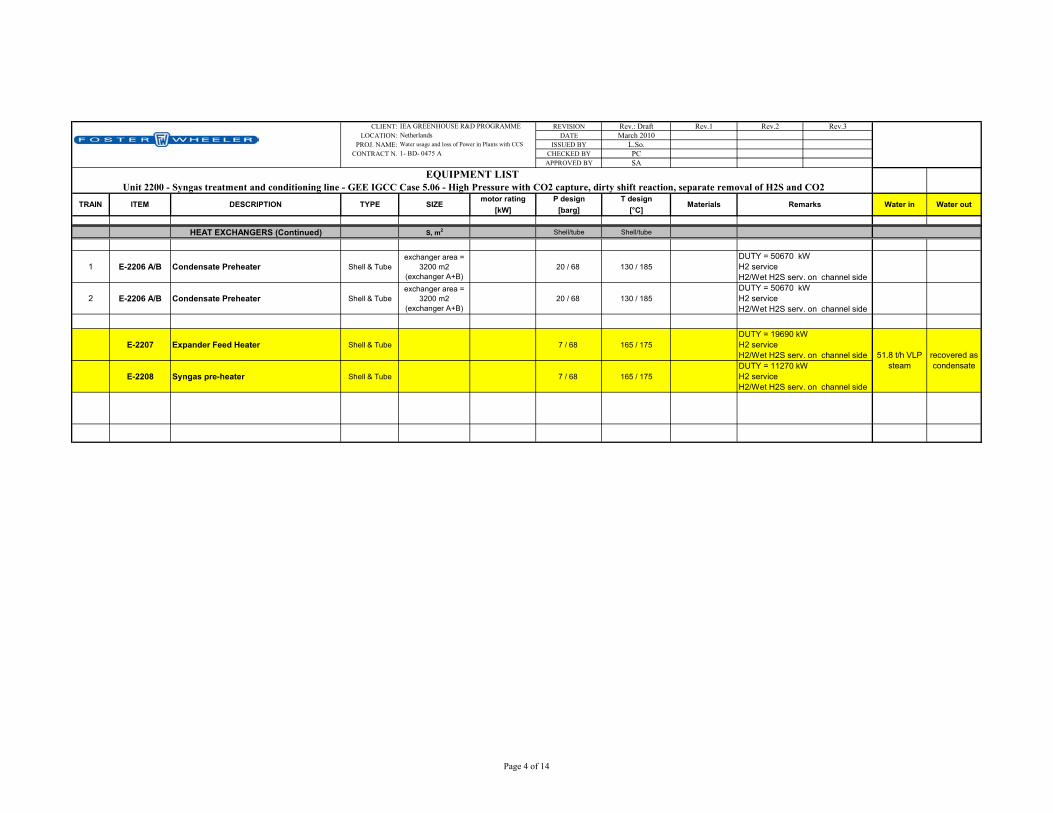
CLIENT: REVISION Rev.: Draft Rev.1 Rev.2 Rev.3LOCATION: DATE March 2010
PROJ. NAME: ISSUED BY L.So.CONTRACT N. CHECKED BY PC
APPROVED BY SA
motor rating P design T design[kW] [barg] [°C]
Water in Water outMaterials
IEA GREENHOUSE R&D PROGRAMMENetherlandsWater usage and loss of Power in Plants with CCS1- BD- 0475 A
SIZE
EQUIPMENT LIST Unit 2200 - Syngas treatment and conditioning line - GEE IGCC Case 5.06 - High Pressure with CO2 capture, dirty shift reaction, separate removal of H2S and CO2
RemarksTRAIN ITEM DESCRIPTION TYPE
HEAT EXCHANGERS (Continued) S, m2 Shell/tube Shell/tube
1 E-2206 A/B Condensate Preheater Shell & Tubeexchanger area =
3200 m2 (exchanger A+B)
20 / 68 130 / 185
2 E-2206 A/B Condensate Preheater Shell & Tubeexchanger area =
3200 m2 (exchanger A+B)
20 / 68 130 / 185
E-2207 Expander Feed Heater Shell & Tube 7 / 68 165 / 175
E-2208 Syngas pre-heater Shell & Tube 7 / 68 165 / 175
51.8 t/h VLP steam
recovered as condensate
DUTY = 50670 kW H2 service H2/Wet H2S serv. on channel sideDUTY = 50670 kW H2 service H2/Wet H2S serv. on channel side
DUTY = 11270 kW H2 service H2/Wet H2S serv. on channel side
DUTY = 19690 kW H2 service H2/Wet H2S serv. on channel side
Page 4 of 14

CLIENT: REVISION Rev.: Draft Rev.1 Rev.2 Rev.3LOCATION: DATE March 2010
PROJ. NAME: ISSUED BY L.So.CONTRACT N. CHECKED BY PC
APPROVED BY SA
motor rating P design T design[kW] [barg] [°C]
Water in Water outMaterials
IEA GREENHOUSE R&D PROGRAMMENetherlandsWater usage and loss of Power in Plants with CCS1- BD- 0475 A
SIZE
EQUIPMENT LIST Unit 2200 - Syngas treatment and conditioning line - GEE IGCC Case 5.06 - High Pressure with CO2 capture, dirty shift reaction, separate removal of H2S and CO2
RemarksTRAIN ITEM DESCRIPTION TYPE
DRUMS D,mm x TT,mm
1 D-2201 Condensate Separator Vertical 68 205 Wet H2S service/H2 service
2 D-2201 Condensate Separator Vertical 68 205 Wet H2S service/H2 service
1 D-2202 Condensate Separator Vertical 68 185 Wet H2S service/H2 service
2 D-2202 Condensate Separator Vertical 68 185 Wet H2S service/H2 service
1 D-2203 A/B Condensate Separator Vertical 68 105
2 D-2203 A/B Condensate Separator Vertical 68 105
D-2204 Process Condensate Accumulator Horizontal 68 190
PUMPS Q,m3/h x H,m
P-2201 A/B Process condensate pump centrifugal
REACTOR D,mm x TT,mm
597.8 t/h condensate to Gasification;
12 t/h contaminated condensate to
SWS
One operating, one spare
Equipped with demister Wet H2S service/H2 service
Equipped with demister Wet H2S service/H2 service
1 R-2201 Shift Catalyst Reactor vertical 68 464
2 R-2201 Shift Catalyst Reactor vertical 68 464
0.1 t/h water loss to COS
hydrolysis; 183.4 t/h water loss in Shift reaction.
H2 service Wet H2S service
H2 service Wet H2S service
Page 5 of 14
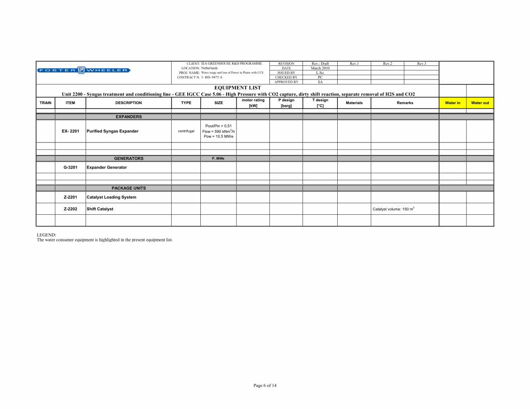
CLIENT: REVISION Rev.: Draft Rev.1 Rev.2 Rev.3LOCATION: DATE March 2010
PROJ. NAME: ISSUED BY L.So.CONTRACT N. CHECKED BY PC
APPROVED BY SA
motor rating P design T design[kW] [barg] [°C]
Water in Water outMaterials
IEA GREENHOUSE R&D PROGRAMMENetherlandsWater usage and loss of Power in Plants with CCS1- BD- 0475 A
SIZE
EQUIPMENT LIST Unit 2200 - Syngas treatment and conditioning line - GEE IGCC Case 5.06 - High Pressure with CO2 capture, dirty shift reaction, separate removal of H2S and CO2
RemarksTRAIN ITEM DESCRIPTION TYPE
EXPANDERS
EX- 2201 Purified Syngas Expander centrifugalPout/Pin = 0,51
Flow = 590 kNm3/h Pow = 10.5 MWe
GENERATORS P, MWe
G-3201 Expander Generator
PACKAGE UNITS
Z-2201 Catalyst Loading System
Z-2202 Shift Catalyst
LEGEND:The water consumer equipment is highlighted in the present equipment list.
Catalyst volume: 150 m3
Page 6 of 14

CLIENT: REVISION Rev.: Draft Rev.1 Rev.2 Rev.3LOCATION: DATE March 2010
PROJ. NAME: ISSUED BY L.So.CONTRACT N. CHECKED BY PC
APPROVED BY SA
motor rating P design T design[kW] [barg] [°C]
PACKAGESSulphur Prod.=66.8 t/d
Acid Gas from AGR = 485 kmol/h 6 65
Sour gas from Gasif. = 200 kmol/h 5 110
Expected Treated Tail Gas=622 kmol/h 33 70
Sulphur content = 99,9 wt min (dry basis)
Sulphur content = 17.94 % (wet basis)
Sulphur content = 1,1 % (wet basis)
Water in Water out
5.6 t/h BFW to steam
generators+
3.1 t/h water in sour gas and from reaction
2.5 t/h steam to Plant network;3.0 t/h steam condensate to
condensate unit3.1 t/h sour
water to WWT; 0.1 t/h blowdown
water to WWT
IEA GREENHOUSE R&D PROGRAMMENetherlandsWater usage and loss of Power in Plants with CCS1- BD- 0475 A
Major components (wet basis): CO2 = 83.71%, H2=2.88%, N2 = 12.47%
Z-2400 Sulphur Recovery Unit and Tail Gas Treatment Package (two Sulphur Recovery Unit, each sized for 100% of the capacity and one Tail Gas Treatment Unit sized for 100% of capacity, including Reduction Reactor and Tail Gas Compressor)
EQUIPMENT LIST Unit 2400 - Sulphur Recovery Unit & Tail Gas Treatment - GEE IGCC Case 5.06 - High Pressure with CO2 capture, dirty shift reaction, separate removal of H2S and CO2
RemarksTRAIN ITEM DESCRIPTION TYPE SIZE Materials
LEGEND:The water consumer equipment is highlighted in the present equipment list.
Page 7 of 14

CLIENT: REVISION Rev.: Draft Rev.1 Rev.2 Rev.3LOCATION: DATE March 2010
PROJ. NAME: ISSUED BY L.So.CONTRACT N. CHECKED BY PC
APPROVED BY SA
motor rating P design T design[kW] [barg] [°C]
Compression package
Compressor 3 stage compressor
165000 Nm3/h x overall β = 73; β per stage = 4.5
approx
motor = 20 MW each machine SS
Intercoolers Shell & tube 19 MWthtubes: Titaniumshell: SS
Dryer Water to WWT (0.8 t/h)
Materials
IEA GREENHOUSE R&D PROGRAMMENetherlandsWater usage and loss of Power in Plants with CCS1- BD- 0475 A
RemarksTRAIN ITEM DESCRIPTION TYPE SIZE
2 x 50% machines (165000 Nm3/h each)
6 shell and tube, 19 MWth eachsea water heat exchangers
Water in Water out
EQUIPMENT LIST Unit 2500 - CO2 compression - GEE IGCC Case 5.06 - High Pressure with CO2 capture, dirty shift reaction, separate removal of H2S and CO2
LEGEND:The water consumer equipment is highlighted in the present equipment list.
Page 8 of 14
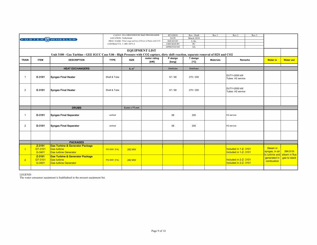
CLIENT: REVISION Rev.: Draft Rev.1 Rev.2 Rev.3LOCATION: DATE March 2010
PROJ. NAME: ISSUED BY L.So.CONTRACT N. CHECKED BY PC
APPROVED BY SA
motor rating P design T design[kW] [barg] [°C]
HEAT EXCHANGERS S, m2 Shell/tube Shell/tube
1 E-3101 Syngas Final Heater Shell & Tube 67 / 68 270 / 200
2 E-3101 Syngas Final Heater Shell & Tube 67 / 68 270 / 200
DRUMS D,mm x TT,mm
1 D-3101 Syngas Final Separator vertical 68 200 H2 service
2 D-3101 Syngas Final Separator vertical 68 200 H2 service
PACKAGES
1Z-3101
GT 3101Gas Turbine & Generator Package G t bi Steam in
Water in Water out
DUTY=2050 kW Tubes: H2 service
DUTY=2050 kW Tubes: H2 service
RemarksTRAIN ITEM DESCRIPTION Materials
Included in 1 Z 3101
TYPE
IEA GREENHOUSE R&D PROGRAMMENetherlandsWater usage and loss of Power in Plants with CCS1- BD- 0475 A
SIZE
EQUIPMENT LIST Unit 3100 - Gas Turbine - GEE IGCC Case 5.06 - High Pressure with CO2 capture, dirty shift reaction, separate removal of H2S and CO2
1 GT-3101 G-3401
Gas turbine Gas turbine Generator
PG 9351 (FA) 282 MW
2Z-3101
GT-3101 G-3401
Gas Turbine & Generator Package Gas turbine Gas turbine Generator
PG 9351 (FA) 282 MW
LEGEND:The water consumer equipment is highlighted in the present equipment list.
Steam in syngas, in air to turbine and generated in combustion
394.9 t/h steam in flue gas to stack
Included in 2-Z- 3101 Included in 2-Z- 3101
Included in 1-Z- 3101 Included in 1-Z- 3101
Page 9 of 14
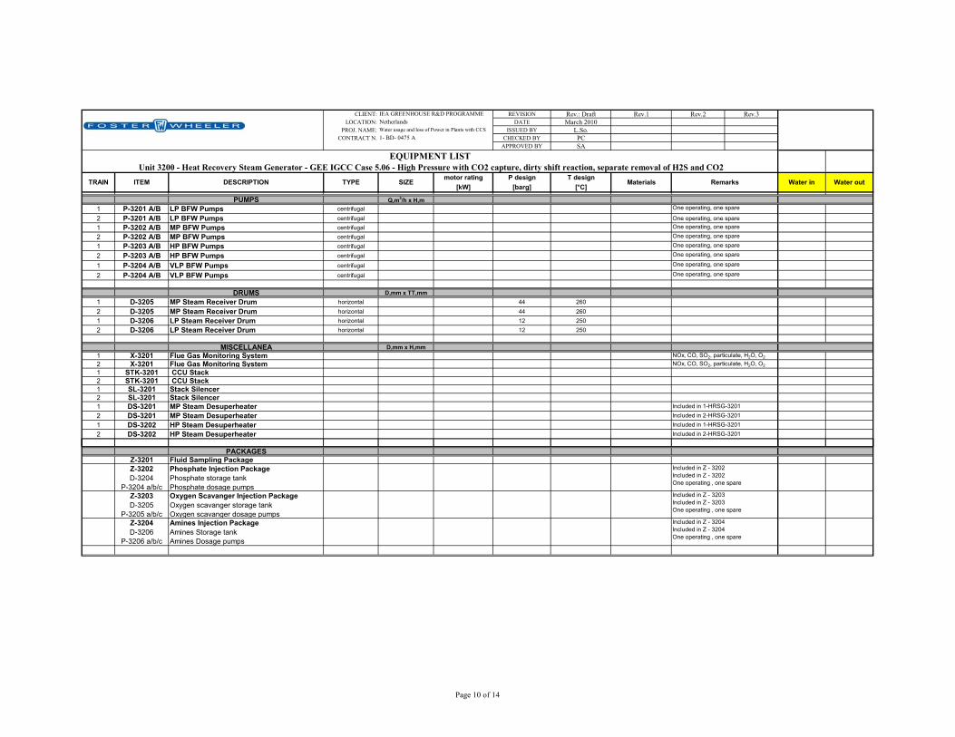
CLIENT: REVISION Rev.: Draft Rev.1 Rev.2 Rev.3LOCATION: DATE March 2010
PROJ. NAME: ISSUED BY L.So.CONTRACT N. CHECKED BY PC
APPROVED BY SA
motor rating P design T design[kW] [barg] [°C]
PUMPS Q,m3/h x H,m1 P-3201 A/B LP BFW Pumps centrifugal2 P-3201 A/B LP BFW Pumps centrifugal One operating, one spare1 P-3202 A/B MP BFW Pumps centrifugal2 P-3202 A/B MP BFW Pumps centrifugal1 P-3203 A/B HP BFW Pumps centrifugal2 P-3203 A/B HP BFW Pumps centrifugal
1 P-3204 A/B VLP BFW Pumps centrifugal
2 P-3204 A/B VLP BFW Pumps centrifugal
DRUMS D,mm x TT,mm1 D-3205 MP Steam Receiver Drum horizontal 44 2602 D-3205 MP Steam Receiver Drum horizontal 44 2601 D-3206 LP Steam Receiver Drum horizontal 12 2502 D-3206 LP Steam Receiver Drum horizontal 12 250
MISCELLANEA D,mm x H,mm1 X-3201 Flue Gas Monitoring System2 X-3201 Flue Gas Monitoring System1 STK-3201 CCU Stack2 STK-3201 CCU Stack1 SL-3201 Stack Silencer2 SL-3201 Stack Silencer1 DS-3201 MP Steam Desuperheater2 DS-3201 MP Steam Desuperheater1 DS-3202 HP Steam Desuperheater2 DS-3202 HP Steam Desuperheater
Water in Water out
Included in 2-HRSG-3201
One operating, one spare
One operating, one spare
NOx, CO, SO2, particulate, H2O, O2
NOx, CO, SO2, particulate, H2O, O2
One operating, one spare
One operating, one spareOne operating, one spare
One operating, one spare
One operating, one spare
Included in 1-HRSG-3201Included in 2-HRSG-3201Included in 1-HRSG-3201
RemarksTRAIN ITEM DESCRIPTION TYPE SIZE Materials
IEA GREENHOUSE R&D PROGRAMMENetherlandsWater usage and loss of Power in Plants with CCS1- BD- 0475 A
EQUIPMENT LIST Unit 3200 - Heat Recovery Steam Generator - GEE IGCC Case 5.06 - High Pressure with CO2 capture, dirty shift reaction, separate removal of H2S and CO2
PACKAGESZ-3201 Fluid Sampling PackageZ-3202 D-3204
P-3204 a/b/c
Phosphate Injection Package Phosphate storage tank Phosphate dosage pumps
Z-3203 D-3205
P-3205 a/b/c
Oxygen Scavanger Injection Package Oxygen scavanger storage tank Oxygen scavanger dosage pumps
Z-3204 D-3206
P-3206 a/b/c
Amines Injection Package Amines Storage tank Amines Dosage pumps
Included in Z - 3203 Included in Z - 3203 One operating , one spare
Included in Z - 3204 Included in Z - 3204 One operating , one spare
Included in Z - 3202 Included in Z - 3202 One operating , one spare
Page 10 of 14

CLIENT: REVISION Rev.: Draft Rev.1 Rev.2 Rev.3LOCATION: DATE March 2010
PROJ. NAME: ISSUED BY L.So.CONTRACT N. CHECKED BY PC
APPROVED BY SA
motor rating P design T design[kW] [barg] [°C]
Water in Water outRemarksTRAIN ITEM DESCRIPTION TYPE SIZE Materials
IEA GREENHOUSE R&D PROGRAMMENetherlandsWater usage and loss of Power in Plants with CCS1- BD- 0475 A
EQUIPMENT LIST Unit 3200 - Heat Recovery Steam Generator - GEE IGCC Case 5.06 - High Pressure with CO2 capture, dirty shift reaction, separate removal of H2S and CO2
HEAT RECOVERY STEAM GENERATOR
1 HRSG-3201 Heat Recovery Steam Generator
Horizontal, Natural Circulated, 4 Pressure Levels, Simple Recovery, Reheated.
1 D-3201 HP steam Drum Included in 1-HRS-32011 D-3202 MP steam drum Included in 1-HRS-32011 D-3203 LP steam drum Included in 1-HRS-3201
1 D-3204 VLP steam drum with degassing section Included in 1-HRS-3201 0.3 t/h steam vented to atm
1 E-3201 HP Superheater 2nd section Included in 1-HRS-32011 E-3202 MP Reheater 2nd section Included in 1-HRS-32011 E-3203 HP Superheater 1st section Included in 1-HRS-32011 E-3204 MP Reheater 1st section Included in 1-HRS-32011 E-3205 HP Evaporator Included in 1-HRS-32011 E-3206 HP Economizer 3rd section Included in 1-HRS-32011 E-3207 MP Superheater Included in 1-HRS-32011 E-3208 MP Evaporator Included in 1-HRS-32011 E-3209 LP Superheater Included in 1-HRS-32011 E-3210 MP Economizer 2nd section Included in 1-HRS-32011 E-3211 HP Economizer 2nd section Included in 1-HRS-32011 E-3212 LP Evaporator Included in 1-HRS-32011 E-3213 LP Economizer Included in 1-HRS-32011 E-3214 MP Economizer 1st section Included in 1-HRS-32011 E-3215 HP Economizer 1st section Included in 1-HRS-32011 E-3216 VLP Evaporator Included in 1-HRS-3201
1.7 t/h blowdown from Steam
Drums
Page 11 of 14

CLIENT: REVISION Rev.: Draft Rev.1 Rev.2 Rev.3LOCATION: DATE March 2010
PROJ. NAME: ISSUED BY L.So.CONTRACT N. CHECKED BY PC
APPROVED BY SA
motor rating P design T design[kW] [barg] [°C]
Water in Water outRemarksTRAIN ITEM DESCRIPTION TYPE SIZE Materials
IEA GREENHOUSE R&D PROGRAMMENetherlandsWater usage and loss of Power in Plants with CCS1- BD- 0475 A
EQUIPMENT LIST Unit 3200 - Heat Recovery Steam Generator - GEE IGCC Case 5.06 - High Pressure with CO2 capture, dirty shift reaction, separate removal of H2S and CO2
HEAT RECOVERY STEAM GENERATOR
2 HRSG-3201 Heat Recovery Steam Generator
Horizontal, Natural Circulated, 4 Pressure Levels, Simple Recovery, Reheated.
2 D-3201 HP steam Drum Included in 2-HRS-32012 D-3202 MP steam drum Included in 2-HRS-32012 D-3203 LP steam drum Included in 2-HRS-3201
2 D-3204 VLP steam drum with degassing section Included in 2-HRS-3201 0.3 t/h steam vented to atm
2 E-3201 HP Superheater 2nd section Included in 2-HRS-32012 E-3202 MP Reheater 2nd section Included in 2-HRS-32012 E-3203 HP Superheater 1st section Included in 2-HRS-32012 E-3204 MP Reheater 1st section Included in 2-HRS-32012 E-3205 HP Evaporator Included in 2-HRS-32012 E-3206 HP Economizer 3rd section Included in 2-HRS-32012 E-3207 MP Superheater Included in 2-HRS-32012 E-3208 MP Evaporator Included in 2-HRS-32012 E-3209 LP Superheater Included in 2-HRS-32012 E-3210 MP Economizer 2nd section Included in 2-HRS-32012 E-3211 HP Economizer 2nd section Included in 2-HRS-32012 E-3212 LP Evaporator Included in 2-HRS-32012 E-3213 LP Economizer Included in 2-HRS-32012 E-3214 MP Economizer 1st section Included in 2-HRS-32012 E-3215 HP Economizer 1st section Included in 2-HRS-32012 E-3216 VLP Evaporator Included in 2-HRS-3201
1.7 t/h blowdown from Steam
Drums
LEGEND:The water consumer equipment is highlighted in the present equipment list.
Page 12 of 14

CLIENT: REVISION Rev.: Draft Rev.1 Rev.2 Rev.3LOCATION: DATE March 2010
PROJ. NAME: ISSUED BY L.So.CONTRACT N. CHECKED BY PC
APPROVED BY SA
motor rating P design T design[kW] [barg] [°C]
HEAT EXCHANGERS S, m2 shell / tube shell / tube
E-3304 Blow-Down Cooler Shell & Tube 20,2 / 4 58 / 140
DRUMS D,mm x TT,mm
D-3301 Flash Drum vertical 3.5 230D-3302 Continuous Blow-down Drum vertical 3.5 140D-3303 Discontinuous Blow-down Drum vertical 3.5 140
PACKAGES
Z-3301 Steam Turbine & Condenser Package
TB-3301 Steam Turbine 428 MWe grossE-3301A/B Inter/After condenser
E-3302 Gland Condenser
E-3303 Steam Condenser shell & tube 702 MW thtubes: titanium;shell: CS
G-3402 Steam Turbine GeneratorJ-3301 Start-up Ejector
J-3302 A/B Holding Ejector 1st StageJ-3303 A/B Holding Ejector 2nd Stage
P-3301A/B/C Condensate Pumps Centrifugal
Water in Water out
blowdown from Steam Drums
3.3 t/h water to WWT
RemarksTRAIN ITEM DESCRIPTION TYPE SIZE Materials
IEA GREENHOUSE R&D PROGRAMMENetherlandsWater usage and loss of Power in Plants with CCS1- BD- 0475 A
EQUIPMENT LIST Unit 3300 - Steam Turbine and Blow Down System - GEE IGCC Case 5.06 - High Pressure with CO2 capture, dirty shift reaction, separate removal of H2S and CO2
DUTY = 853 kW
Included in Z - 3201Sea water heat exchanger
Included in Z - 3201
Included in Z - 3201
Included in Z - 3201Included in Z - 3201Included in Z - 3201Included in Z - 3201Included in Z - 3201 Two operating, one spare
SL-3301 Start-up Ejector Silencer
LEGEND:The water consumer equipment is highlighted in the present equipment list.
Included in Z - 3201
Page 13 of 14

CLIENT: REVISION Rev.: Draft Rev.1 Rev.2 Rev.3LOCATION: DATE March 2010
PROJ. NAME: ISSUED BY L.So.CONTRACT N. CHECKED BY PC
APPROVED BY SA
motor rating P design T design[kW] [barg] [°C]
PACKAGES
1 G-3401 Gas Turbine Generator2 G-3401 Gas Turbine Generator
G-3402 Steam Turbine Generator
Closed loop water cooler shell and tube 120 MW th plates: titaniumframe: SS
Close loop CW pumps centrifugal 8610 m3/h x 30m 1290 kWe CSWaste water treatment plantSea water pumps submerged 20000 m3/h x 20m 1640 kWe casing, shaft: SS;
impeller: duplexSeawater chemical injectionSea water inlet/outlet works
Water in Water out
Included in Z- 3301Included in 2 -Z- 3101
IEA GREENHOUSE R&D PROGRAMMENetherlandsWater usage and loss of Power in Plants with CCS1- BD- 0475 A
sea water
SIZE Materials
EQUIPMENT LIST Unit 3400 - Electric Power Generation - GEE IGCC Case 5.06 - High Pressure with CO2 capture, dirty shift reaction, separate removal of H2S and CO2
RemarksTRAIN ITEM DESCRIPTION TYPE
Included in 1 -Z- 3101
7 pumps in operation + 1 spare
MISCELLANEA EQUIPMENT
1 pump in operation + 1 spare
LEGEND:The water consumer equipment is highlighted in the present equipment list.
Page 14 of 14