


IE1206 Embedded Electronics - Amazon Web...
38
IE1206 Embedded Electronics Transients PWM Phasor jω PWM CCP KAP/IND-sensor Le1 Le3 Le6 Le8 Le2 Ex1 Le9 Ex4 Le7 Written exam William Sandqvist [email protected] PIC-block Documentation, Seriecom Pulse sensors I, U, R, P, serial and parallell Ex2 Ex5 Kirchoffs laws Node analysis Two ports R2R AD Trafo, Ethernetcontact Le13 Pulsesensors, Menuprogram Le4 KC1 LAB1 KC3 LAB3 KC4 LAB4 Ex3 Le5 KC2 LAB2 Two ports, AD, Comparator/Schmitt Step-up, RC-oscillator Le10 Ex6 LC-osc, DC-motor, CCP PWM LP-filter Trafo Le12 Ex7 Display Le11 • Start of programing task • Display of programing task
Transcript of IE1206 Embedded Electronics - Amazon Web...

IE1206 Embedded Electronics
Transients PWM
Phasor jω PWM CCP KAP/IND-sensor
Le1
Le3
Le6
Le8
Le2
Ex1
Le9
Ex4 Le7
Written exam
William Sandqvist [email protected]
PIC-block Documentation, Seriecom Pulse sensors I, U, R, P, serial and parallell
Ex2
Ex5
Kirchoffs laws Node analysis Two ports R2R AD
Trafo, Ethernetcontact Le13
Pulsesensors, Menuprogram
Le4
KC1 LAB1
KC3 LAB3
KC4 LAB4
Ex3 Le5 KC2 LAB2 Two ports, AD, Comparator/Schmitt
Step-up, RC-oscillator
Le10 Ex6 LC-osc, DC-motor, CCP PWM
LP-filter Trafo Le12 Ex7 Display
Le11
• Start of programing task
• Display of programing task

William Sandqvist [email protected]
ASCII-table
http://ascii-table.com/
Every letter is stored in a Byte, char.
”Hej!” 48 65 6A 21 00 01001000 01100101 01101010 00100001 00000000
PICKit 2 UART Tool uses \r\n

William Sandqvist [email protected]
Serial communication parallell-serial-parallell conversion
Idle Idle Stop bit
Data bits
Start bit Parity/bit9

William Sandqvist [email protected]
UART-unit
The serial/parallel conversion on a bit level is often taken care of with a special circuit called UART (Universal Asynchronous Receiver/Transmitter), so that the processor can deliver/receive full characters.
Such unit is built into most PIC processors (USART/EUSART).

Serial communication unit
William Sandqvist [email protected]
The receiver can receive up to three characters before the processor needs to act.
The transmitter can hold two characters in the queue from the processor.
Independently run serial communication unit
During communication, the processor can do other things!

William Sandqvist [email protected]
PIC16F690 EUSART PIC 16F690 contains a built-in serial communication unit, EUSART (Enhenced Universal Synchronous or Asynchronous Receiver and Transmitter). As the name implies, this device is useful for both synchronous and asynchronous serial communication, but we will only use it for asynchronous serial communications.
EUSART consists of three parts. • SPBRG ( Serial unit Programable BaudRateGenerator ) is a programable Baudgenerator for the transmission speed. • USART Transmitter is the transmitter part. • USART Reciever is the reciever part.

William Sandqvist [email protected]
Bitrate In serial communication, it is necessary that the transmitter and receiver are operating with the same in advance agreed upon rate. The rate at which bits are transferred is called the Bitrate [bit/sec].
Frequently used Bitrate's are multiples of 75 bit/sek as: 75, 150, 300, 600, 1200, 9600, 19200 och 38400 bit/sek.
Bitrate clock is taken from a baud rate generator.

William Sandqvist [email protected]
Baud Rate Generator BRG
One bit BRGH determines the low-speed or high-speed mode. One bit BRG16 introduces 16-bit divisor.
/* 9600 Baud @ 4 MHz */ BRG16=0; BRGH=1; SPBRG = 26-1;
A register SPBRG contains a divisor 8/16-bits.
(16bit) 8bit
• Our settings:

William Sandqvist [email protected]
Baud Rate Generator BRG
The extensive setting options are there to be able to find a combination that gives the most accurate bitrate as possible.
Two processors that communicate asynchronously with each other must have Bitrate's that conforms better than ±2,5%. Otherwise you risk the communication to be distorted.

William Sandqvist [email protected]
Transmitter
To send a character, it is enough to put it in the TXREG register. When the transmitterregister TSR is "redy" the character is copied to this and is shifted out serial on the pin TX/CK. If there is If you have a further character to send you can now put it in the "waiting queue" for TXREG. As fast as TSR is empty the next character will be loaded from TXREG automaticaly to TSR.
In the blockdiagram the flag TXIF ( Transmitter Interupt Flag ) will tell if the transmitter register TXREG is full or not. The flag is zeroed automatically when a character is loaded to TSR.

William Sandqvist [email protected]
Transmitter settings
bit 6 = 0 TX9: No nine bit transmission.
bit 5 = 1 TXEN: Transmit Enable bit. Must be on.
bit 4 = 0 SYNK: Usart mode select bit. We chose asynchronous operation.
bit 2 = 1 BRGH: High Baudrate select bit. We chose high speed mode.
bit 1 TRMT: Flag is ”1” if TSR is empty.

William Sandqvist [email protected]
Reciever Characters received from the pin RX/DT to the reciever register RSR. When the reception of a character is done it is brought over to RCREG which is a FIFO-buffer. This buffer contains two characters that are read in the order they arrived. The buffer means that a program can do other things during the time it takes to receive three characters. The flag RCIF tells if there are characters in the buffer or not. This flag is zeroed automatically when the buffer is read and empty, after one/two characters.
Flags OERR, FERR warns for erroneously received characters

William Sandqvist [email protected]
Reciever settings
bit 7 = 1 SPEN: Enables the serieal port.
bit 6 = 0 RX9: No recieve of nine bit.
bit 4 = 1 CREN: Continuous Receive Enable bit. Use the buffer.
bit 2 and bit 1 FERR OERR Flags for erroneously received characters.
The bit/bitvariabele RCIF indicates when there are characters to fetch.

William Sandqvist [email protected]
Initiation of the serieal port void initserial( void ) /* initialise serialcom port 16F690 */ { SPEN = 1; BRGH = 1; /* Async high speed */ BRG16= 0; /* SPRG n is 8-bit */ TXEN = 1; /* transmit enable */ SPBRG = 26-1; /* 9600 Baud @ 4 MHz */ CREN = 1; /* Continuous receive */ RX9 = 0; /* 8 bit reception */ TRISB.7 = 0; /* TX is output */ TRISB.5 = 1; /* RX is input */ }
• Done once in the beginning of program.

William Sandqvist [email protected]
Seriecom-functions char getchar( void ) /* recieves one char */ { char d_in; while ( !RCIF ) ; /* wait for char */ d_in = RCREG; return d_in; }
void putchar( char d_out ) /* sends one char */ { /* wait until previous character transmitted */ while (!TXIF) ; TXREG = d_out; }
Note! Blocking function! Here you will wait until a character is received!

William Sandqvist [email protected]
Warning! Recievern can lock!
The program must read the receiver unit before it has received three characters - otherwise it lock itself! When connecting the serial connector one may "trembles" on hand such that the "contact bounces" becomes many characters received. If the receiving device then "freezes" this is obviously a very difficult/impossible "bug" to find! The solution is an unlocking routine to use if necessary. You should call such a unlocking routine directly before you expects input via the serial port.

William Sandqvist [email protected]
OverrunRecover() void OverrunRecover( void ) { char trash; trash = RCREG; trash = RCREG; CREN = 0; CREN = 1; }
• Unlocking procedure.

William Sandqvist [email protected]
Seriecom - Hardware
Place jumpers between PIC-processorn serial port to the programing wires (Or, Red).
1) PICKIT 2 UART Tool by the programing wires
Jumpers on the starterkit
threestate
threestate

William Sandqvist [email protected]
Seriecom – Console program 1) PICKIT 2 UART Tool, can be used as a console program through the programing wires.
/* not disturb UART-Tool */
TRISA.0 = 1; TRISA.1 = 1; initserial();
Threestate on the programing wires!

William Sandqvist [email protected]
Seriecom - Hardware 2) PC with serial port
Invert signals to/from PIC-processor serial port before it is connected to PC serial port. (Should be ±12V, but inverters use to be enough). (There are special circuits that generate ±12V signals for serial communication.)
Inverter
ICL7667
PC-serieport

William Sandqvist [email protected]
Serial communication USB-serial-TTL
3) FTDI TTL232R connects directly to the processor pins.
Most PC lacks nowadays serial port, a driver can install a virtual USB serial port.
The driver is now already in Windows
Noninverted logic levels

William Sandqvist [email protected]
Console program to PC
PuTTY
If you uses a USB-virtual serial port – first find out the COM port number (with Device / Device Manager)…
PuTTY

William Sandqvist [email protected]
Testprogram: echo()/crypto() void main( void) { char c; TRISB.6 = 1; /* not to disturb UART-Tool */ TRISB.7 = 1; /* not to disturb UART-Tool */ initserial(); delay10(100); /* 1 sek delay */ /* 1 sek to turn on VDD and Connect UART-Tool */ while( 1) { c = getchar( ); /* input 1 character */ if( c == '\r'||c == '\n') putchar(c); else putchar(c); /* echo the character */ /* putchar(c+1) => Crypto! */ }
}
If PIC-processor ”echoes” the characters so does the communication work.
Safer version: crypto ! A→B

William Sandqvist [email protected]

William Sandqvist [email protected]
Bit-banging It is very common to program serial communication "bit by bit". Any port pin can be used. This is a very good debugging tool.
A suitable bitrate is then 9600. T = 1/9600 = 104.17 µs. If the processor's clock frequency is 4 MHz a delay loop that takes 104 instructions is needed.
/* delay one bit 104 usec at 4 MHz */ /* 5+18*5-1+1+9=104 without optimization */ i = 18; do ; while( --i > 0); nop();
Loock at the assembly code and count the instructions. Every instruction takes 1 µs.

William Sandqvist [email protected]
Bits and extra bits
The asynchronous transfer technique means that for every byte one adds extra bits that will make it possible to separate out the byte from the bitstream. Often you in addition put in a bit for error indication.
William Sandqvist [email protected]
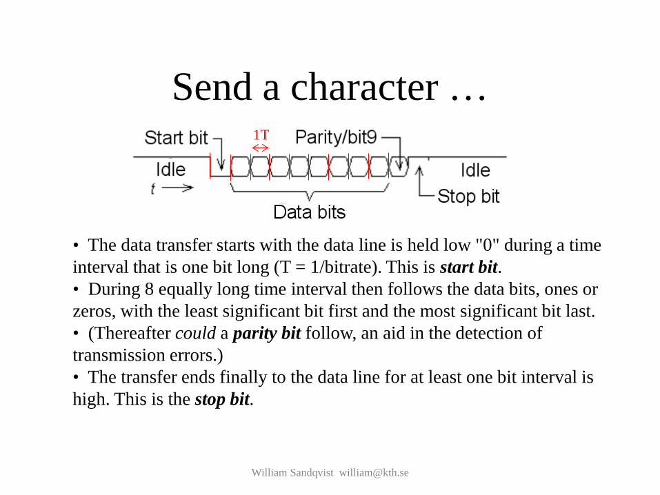
Send a character …
• The data transfer starts with the data line is held low "0" during a time interval that is one bit long (T = 1/bitrate). This is start bit. • During 8 equally long time interval then follows the data bits, ones or zeros, with the least significant bit first and the most significant bit last. • (Thereafter could a parity bit follow, an aid in the detection of transmission errors.) • The transfer ends finally to the data line for at least one bit interval is high. This is the stop bit.
1T

William Sandqvist [email protected]
Recieve a character
The reception of data is done by first waiting for the start bit negative edge, and then register the first data after 1.5T delay and then the next data bits after 1T (registration at the data bits "midpoints").
The receiver is ”resynchronized" again at every start bit edge.
1,5T 1T

William Sandqvist [email protected]
Rotation av numbers
PIC-processors has two instruktions for ”rotate” numbers RLF and RRF. These instructions, we need in the future…

William Sandqvist [email protected]
Cc5x has internal functions rl() and rr()
char rl( char );
char rr( char );
C language has two shift operators shift right >> and shift left << , no actual "rotate" -operator does not exist.
In order to nevertheless be able to use PIC processors' rotation instructions, the compiler Cc5x has added two internal functions char rl( char ); and char rr( char );. These functions directly generates assembly instryctions RLF and RRF.
The Carryflag is reached as a internal bit variable bit Carry;

William Sandqvist [email protected]
Debug-comunication
void initserial( void ) /* init PIC16F690 serialcom */ { ANSEL.0 = 0; /* No AD on RA0 */ ANSEL.1 = 0; /* No AD on RA1 */ PORTA.0 = 1; /* marking line */ TRISA.0 = 0; /* output to PK2 UART-tool */ TRISA.1 = 1; /* input from PK2 UART-tool */ }
PICKit2 UART-tool can be used as a simple debuging tool. The same wires that are used for the chip programming are used by the UART-tool for serial communication.
What is needed is therefore a bitbanging-routine for serial communication with these pins.
Chip-programing and comunication.

void putchar(char d_out) { char count, i; Serial_out = 0; /* set startbit */ for(count = 10; count > 0; count--) { /* delay 104 usec */ i = 18; do ; while( --i > 0); nop(); Carry = 1; d_out = rr(d_out); Serial_out = Carry; } }
William Sandqvist [email protected]
void putchar( char )

William Sandqvist [email protected]
char getchar( void ) char getchar( void ) { char d_in, count, i; while( Serial_in == 1) /* wait for startbit */; /* 1.5 bit 156 usec no optimization */ i = 28; do ; while( --i > 0); nop(); nop2(); for(count = 8; count > 0; count--) { Carry = Serial_in; d_in = rr( d_in ); /* 1 bit 104 usec no optimization */ i = 18; do ; while( --ti > 0); nop(); } return d_in; }

William Sandqvist [email protected]
Testprogram: squarewave
9600 bit/sek. If you transmitts continuously 8 bit with start bit and stop bit the letter ’U’ (1010101010) you will get a squarewave with f = 4800 Hz. This test is useful to know.
while(1) putchar(’U’);
You can check if the bitrate is correct with an oscilloscope.

If you don’t have any oscilloscope?
William Sandqvist [email protected]
while(1) putchar(’U’);
PIC Tx
PICKit2 Logic Tool
We can see details such as that the stop bit are a little longer than the other bits. To measure the frequency, click the markers in place with left and right mouse buttons. The frequency is 4785 Hz (≈4800).

William Sandqvist [email protected]


