
Plate Tectonics Earth’s Interior Pangaea Plate Movement Plate Boundaries.

Measure
Select Measure tab.
Test Measure Plate.
Assign a plate ID.
Accept batch.
Click
Click
Click
Review zone measurements
If all zones are detected click Finish, if not repeat step 8and ensure all of thezones are central.
11
Click
Identify zones10 From Image click on an area of the disc or well to pick colour,repeat for zone and thebackground. Be sure to takerepresentative samplesfrom across the plate.
Click Next.
Sample
Sample
Sample
ProtoCOL 3 is now ready to make the first measurement
Synbiosis Europe and International Headquarters:
Beacon House Nuffield Road Cambridge CB4 1TF UK
Tel: +44 (0)1223 727125 Fax: +44 (0)1223 727101
email: [email protected]
Synbiosis USA Headquarters:
5123 Pegasus Court Suite Q Frederick MD 21704 USA
Tel: 800-686-4451/301-662-2863
email: [email protected]
Website: www.synbiosis.com
All trademarks acknowledged A0029.06.1926
SYNBIOSISPROTOCOL 3 QUICK GUIDE
12

Thank you for ordering your Synbiosis ProtoCOL 3 automated colony counter and zone sizing system.
If you ordered your device with a touchscreen PC, please follow from page 2 but ignore pages 5-13 (SOFTWARE INSTALLATION) as this has already been completed for you.Alternatively if you ordered your device without a touchscreen PC, please follow from page 5 onwards.
All guides and validation procedures ordered will be located on the computer’s desktop if you ordereda PC, or on the installation USB, if you didn’t.
Should you require any additional assistance installing your device, please contact [email protected].
GETTING STARTEDCONTENTS
1
GETTING STARTED
CONNECTING YOUR TOUCH SCREEN PC
SOFTWARE INSTALLATION
HOW TO ADD A USER
COUNT VALIDATION PROCEDURE
1
2
5
14
18
ZONE VALIDATION PROCEDURE
TOTAL PLATE COUNT BATCH SET-UP
INHIBITION ZONE BATCH SET-UP
20
22
24

2 3
CONNECTING YOUR TOUCH SCREEN PC
Attach bracket and PC to ProtoCOL 3 body
Unpack ProtoCOL 3Unpack the instrument and the PC and place on a secure level surface.
Attach monitor leads
Attach leads to PC and monitor
Attach the leads to the PC and to the monitor before securing the monitor onto the bracket (step 5). They are labelled to help you.
Attach monitor toPC/bracket
Slide the bracket (attachedto the monitor) over the top, lining the two pins with holes in monitor bracket - taking care to feed the cables under the monitor so as not to impede the movement of the monitor.
Secure the monitor onto the bracket using the 4 screws.
5
4
3
2
1
Attach the black bracket with PC to the instrument via the silver mounting plate as shown. The four screws are secured using a Phillips screwdriver (not supplied).
Leave the three leads free and sitting between the bracket as shown.
Attach the 2 monitor leads to the monitor before attaching the monitor to the PC/bracket. Ensure that the ferrite is further from the monitor sothat it does not impedemonitor positioning.

54
Attach power cords to the mains power blocks
There are 2 power leads found at the back of the ProtoCOL 3 system. Attach the mains cables provided to the power blocks and plug into a socket.
THE DEFAULT LOGIN DETAILS FOR THE PROTOCOL 3 PLUS ARE
Username: P3Admin
Password: The unit’s serial number in capitals (located on the rear of the device)
SOFTWARE INSTALLATION
Start PCLog onto PC as an Administrator and shut all running software down.
Insert the Synbiosis USB flash drive
Browse to the flash drive in Windows named ‘Software’.
Install Microsoft.net Framework
Run SetupFramework.exe. Follow the on-screen instructions, performing a system restart if prompted. If you are prompted that this program is already installed then proceed to the next step.
Install SQL Server DatabaseProtoCOL 3 software requires Microsoft’s SQL Server.If you already have a SQL server at a remote location press OK and go to step 5, otherwise press Cancel and follow step 4.
Run SetupP3SqlServer.exe following on-screen instructions.
Install the ProtoCOL software
Run Setup.exe following on-screen instructions.
5
4
3
2
16

Press Next.
Select the device you are using from the list and press Next.
Select any additional hardware you have purchased from the list then click Next.
6
Connect the ProtoCOL 3
Connect the power cord to the ProtoCOL 3 and plug the unit in.
Connect the camera USB cable from the ProtoCOL 3 unit to a spare USB port in the PC.
Switch on the ProtoCOL 3 using the switch on the side of the unit.
7
Press Next or select
an alternative folder.
Press Install.
Press Next.
Press Next or select
an alternative install
location.
9
8
7
6
13
12
11
10

8
Press Finish.
Press Next.
Press Install.
Press Install.
9
Press Next.
Press Finish.
The Database Updater application will appear. If this box disappears after a few seconds then skip to step 25. If the box remains on display then this means the database has not been created. If this is the case then press the blue button with three dots and go to step 22.
Press Finish.
21
20
19
18
17
16
15
14

10
Press the Update button. If any database updates are required they will be applied and the dialogwill close.
The data paths window will appear. Enter a name for the database e.g. (ProtoCOL DB).
Press the New Database button (on the right hand side of the DatabaseName). You will see amessage saying “Database Successfully Created”, press OK, then press OK again on the Data Paths window.
23
22
Please Note: After the installation of the camera and serial drivers the installer will check to see if the user is running Windows 10. If you are installing ProtoCOL 3 ona Windows 10 computer the installation wizard will not appear. Instead you will be asked to confirm you are using a USB dongle to license the software.
If Windows 10 is being run then a prompt will appear with the dialog below.
If OK is selected, the dongle drivers will be updated to the correct version and the install wizard will not run. The user will receive the following message:
“Completed USB dongle software installation. Please connect your USB dongle licence following completion of the ProtoCOL 3 software installation”.
If Cancel is selected the normal install wizard will appear later so the media key method of installing a licence can be used. The install licence is availableafter installation via : Windows Start->Synbiosis->Support->Install Wizard
If the machine did not activate automatically the licensing wizard will appear. Select the appropriate method for licensing and press Next. If using a hardware key (a USB dongle) do not connect the key until instructed to by the wizard. The pages that follow will vary depending on the selection.
24
Enter the media key provided in yourinstallation kit, also located on the USB.
11
Software Key Activation Method
Copy and paste theinformation highlightedin blue and email to [email protected].
An email will be sent back with a security code to use in the next step. (Please note that the email does not need to be sent from the device. The sender will receive the code).
Enter the security code received from [email protected] and click Next.
Your activation is now complete. Press Finish.

Add Users to user groups
HOW TO ADD A USER (page 14). This is an important step and the
device will not function correctly unless the users have
been set up.
27
12
25
Select the USB key.
Click Next.
Hardware Key Activation Method
Remove all connected USB dongles from the PC.
Click Next.
Insert hardware key.
Click Next.
The installation is now complete. Press Finish.
Press Finish.
The final page will vary depending on the licensing type.
13
Run the calibration installer
Browse to the Synbiosis USB flash drive in Windows and open the “Calibration” folder.
Run the “SetupCalibration” program and then follow the on screeninstructions.
26
Run ProtoCOL 3 software
28
Log on to the software and ensure the lights cycle Red, Blue and
Green. Click on the image tab and select live image to ensure the
camera produces a live image.

14 15
HOW TOADD A USER
When ProtoCOL 3 is installed, three default user groups are created:
ProtoCOL Admins
ProtoCOL Advanced Users
ProtoCOL Users
Every person using this device needs to be a member of one of these groups
1 Log onto system as Administrator
Access Computer Management2
Access the Control panel.
Select System and Security.
Click on Administrative Tools.
Double click on Computer Management.
3 Accessing the User Groups
Locate and double-click the ProtoCOL
Admins group.
Non Admin accounts need to be added to
the advanced or user level groups instead.
Select Groups.
Expand Local Users and Groups and click
on Group folder.

Add a Group of Users 5
To add a group of users to aProtoCOL group click Advancedon the page entitled “Select Users, Computers or Groups”.
Then click Find Now.
16 17
Add a Single User
To add a single user, enter their Windowsusername in the box labelled “Enter the object names to select” and click Check Names. Click OK to return to the ProtoCOL Admin Properties Dialog and the user will have been added to the ProtoCOL Admins group.
Click Add.
4 6 Add a Group of Users (Cont)
Select the group you want to add and click OK.
Click OK.
Click OK to close the dialog.

18 19
COUNT VALIDATIONPROCEDURE
The purpose of this validation is to confirm that the ProtoCOL 3 system
correctly uses contrast and background to accurately count a set number of
entities in a known area.
Requirements:ProtoCOL 3 / ProtoCOL 3 Plus System
Pour Plate Validation Plate(s)ProtoCOL 3 User Manual
Familiarity with the ProtoCOL 3 software
Figure 1: Example of Pour Plate Validation Plate
Pour Plate Validation Procedure
1. Insert the pour plate validation plate into the ProtoCOL 3 and
close the doors to minimise ambient light.
2. Log on to the system, load the ProtoCOL 3 software and log on
to the software.
3. Next create your Validation Test batch by clicking “New Batch”.
4. Select “Pour Plate” from the module options.
5. Name the batch “Validation Test”.
6. Check the camera exposure by clicking on the “Image” tab and
adjusting the exposure as necessary and capturing the image, it
should be between 200-300 ms.
7. Adjust the graticule (circle) so it is around the colonies.
8. Click on the “Classification” tab and perform the “Colour
Classification” and choose one colour and click “Next”.
9. Set the “Small Particle Slider” to OFF and select the “Split”
option, click “Next”.
10. Click “Finish”.
11. Click on the “Measure” tab, enter a plate ID of ‘1’.
12. Perform a test measurement by clicking “Test Measure Plate”.
Ensure the count displayed matches that on the validation plate
(e.g. 100).
13. ‘Accept’ the batch.
14. Within the new batch, select the “Measure Plate” button and
review the result. The count should match what is stated on
the validation plate.

20 21
ZONE VALIDATIONPROCEDURE
The purpose of this validation is to confirm that the ProtoCOL 3 system
correctly uses contrast and background to accurately measure
known diameters.
Requirements:ProtoCOL 3 system with zone reading
softwareZone Validation Plate
ProtoCOL 3 User ManualFamiliarity with the ProtoCOL 3 software
Figure 1: Example of Zone Validation Plate
Zone Validation Procedure
1. Insert the zone measurement validation plate into the
ProtoCOL 3.
2. Log on to the system, and then log onto the software.
3. Click New Batch.
4. Select “Inhibition Zone” from the module options.
5. Name the batch “Validation Test”.
6. Check the camera exposure by clicking on the “Image” tab and
adjusting the exposure as necessary between 200-250ms.
When image is acceptable click “Capture Image”.
7. Click the “Zone Classification” button, choose the “Ring”
configuration and leave the number set to 6. Adjust the size of
the zones as needed (if necessary, move individual zones by
checking the box entitled “Move Individual Zones”) to ensure
the black zones are directly in the centre of the
6 measurement frames and click “Next”.
8. Select “No Discs/Wells”, click “Next”.
9. Highlight “Zone Colour” and click on one of the black zones to
identify its colour. Highlight “Background Colour” and click on
the background to identify its colour, Click “Next”.
10. Review measurements. If any are offset repeat Classification
and ensure the black zones are directly in the centre of the
6 measurement frames.
11. Press “Finish”.
12. Complete the zone classification by selecting the
“Measure” tab and perform a test measurement by clicking
“Test Measure Plate”.
13. The measurements should be within +/- 0.5mm of those stated
on the validation plate.
14. On the “Measure” tab, assign a name/number to the plate ID.
15. Accept the Batch.
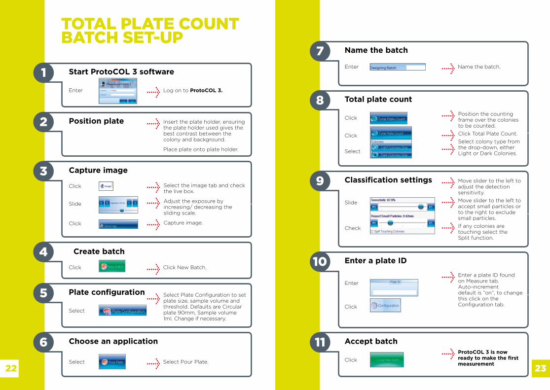
TOTAL PLATE COUNTBATCH SET-UP
Start ProtoCOL 3 software
Log on to ProtoCOL 3.
1
2 Position plate Insert the plate holder, ensuring the plate holder used gives thebest contrast between thecolony and background.
Place plate onto plate holder.
3 Capture image
Click
Slide
Click
Create batch4
5 Plate configuration Select Plate Configuration to set plate size, sample volume andthreshold. Defaults are Circularplate 90mm, Sample volume 1ml. Change if necessary.
6 Choose an application
Click New Batch.Click
Select
Select Pour Plate.Select
23
7 Name the batch
Name the batch.
8Position the counting frame over the colonies to be counted.
Click Total Plate Count.
Select colony type from the drop-down, eitherLight or Dark Colonies.
Total plate count
Click
Click
Select
9 Move slider to the left to adjust the detectionsensitivity.
Move slider to the left toaccept small particles or to the right to excludesmall particles.
If any colonies are touching select theSplit function.
Classification settings
Slide
Check
10Enter a plate ID found on Measure tab.Auto-incrementdefault is “on”, to change this click on theConfiguration tab.
Enter a plate ID
Enter
Click
11 Accept batchProtoCOL 3 is now ready to make the first measurement
Enter
Click
22
Enter
Select the image tab and check the live box.
Adjust the exposure by increasing/ decreasing thesliding scale.
Capture image.

INHIBITION ZONE BATCH SET-UP
Start ProtoCOL 3 software
Log on to ProtoCOL 3.
1
2 Position plate Insert the plate holder, ensuring the plate holder used gives thebest contrast between thezone and background.
Place plate onto plate holder.
3Select the image tab and check the live box.
Adjust the exposure by increasing/ decreasing thesliding scale.
Capture image.
Capture image
Click
Slide
Click
Create batch4
5 Plate configuration
Click New Batch.Click
Select
24 25
6 Choose an application
Select Inhibition Zone.Select
7 Name the batch
Name the batch.Enter
Enter
Select Plate Configuration to set plate size, sample volume andthreshold.
Zone classification
Select
Click
Click
Select Zone Classification tab.
Select type of zone frame and the number of zones required. Position the grid directly over the zones. To move individualmeasuring circles check the boxand setting circle to themaximum zone size.
Zones can also be named on this page by clicking RenameZones.
9 Indicate whether discs or wells are present.
If a well or disc is present enter the size of disc/well by enteringthe size directly into the box orby clicking on the text box anddrag the circle to just outsidethe edge of the well or disc. Click Next.
Discs/wells present
Enter
or
8