IDENTIFICATION OF MECHANICAL AND FATIGUE … Abstracts 14SP/3951.pdf · IDENTIFICATION OF...
2
IDENTIFICATION OF MECHANICAL AND FATIGUE CHARACTERISTICS OF POLYMERS FABRICATED BY ADDITIVE MANFACTURING PROCESS Taylor Corbett 1 , Thijs Kok 2 , ChaBum Lee 1 , and Joshua A Tarbutton 1,* 1 Department of Mechanical Engineering University of South Carolina Columbia, South Carolina, United States 2 Department of Aerospace Engineering Delft University of Technology, Delft, Netherlands INTRODUCTION Additive Manufacturing (AM), more commonly known as 3D printing, is the process of building a product or part by applying materials or powders in very thin layers, until the final product has been built. This capability allows for a variety of new design possibilities for AM such as hinge-based mechanisms, shock absorbing castings, integrated gaskets, and so on [1-3]. The process starts with a 3D model in an STL format, which is imported into the AM software. The AM software converts its geometry into horizontal slices in the form of multiple layers with varying thicknesses. Many processes include the use of UV, laser, or thermal- associated technology; such as Selective Laser Sintering (SLS), Fused Deposition Modeling (FDM), and Stereolithography (SLA) [1]. Materials commonly utilized in AM range from resins and polymers to steel. Recently, a number of AM-based devices for precision sensing and actuation applications have been introduced [2,3]. However, the stability characteristics of devices fabricated by AM processes are not well understood and there is very little to indicate what the dominant manufacturing parameters are, how creep and fatigue are affected by different processes and materials, and how to design for stability. Here the physical testing for identifying mechanical and fatigue characteristics including tensile strength and high and low cycle fatigue is conducted in accordance with the applicable ASTM standard. MECHANICAL CHARACTERISTICS Mechanical characteristics of the 3D printed polymeric specimens were identified by using a tension test machine while measuring the applied force and strain. The geometry of the specimen was determined according to the ASTM test standards: 150mm long, 20mm wide and 3mm thick. The test specimens were fabricated by FDM process under 32 printing conditions. Five print settings were varied for testing including layer thickness, extrusion width, printing orientation, feedrate and distance between beads as summarized in Table 1. TABLE 1. Printing conditions. Factors Condition I Condition II Material Acrylonitrile Butadiene Styrene Extruder temp. [°C] 200 Bed temp. [°C] 100 Layer thickness [mm] 0.2 0.3 Extrusion width [mm] 0.35 0.45 Print orientation [Deg.] 0 90 Feedrate [mm/min] 2000 4000 Distance btw beads 0 -0.1 Three sets of each test specimen were fabricated under the same printing conditions, respectively, which indicates that a total of 96 test specimens were tested to obtain the mechanical properties of the polymeric material fabricated by the FDM AM process. FIGURE 1. Results of the averaged maximum material strength of 96 test specimens.
Transcript of IDENTIFICATION OF MECHANICAL AND FATIGUE … Abstracts 14SP/3951.pdf · IDENTIFICATION OF...
IDENTIFICATION OF MECHANICAL AND FATIGUECHARACTERISTICS OF POLYMERS FABRICATED BY ADDITIVE
MANFACTURING PROCESS
Taylor Corbett1, Thijs Kok2, ChaBum Lee1, and Joshua A Tarbutton1,*
1Department of Mechanical EngineeringUniversity of South Carolina
Columbia, South Carolina, United States2Department of Aerospace Engineering
Delft University of Technology, Delft, Netherlands
INTRODUCTIONAdditive Manufacturing (AM), more commonlyknown as 3D printing, is the process of buildinga product or part by applying materials orpowders in very thin layers, until the finalproduct has been built. This capability allows fora variety of new design possibilities for AM suchas hinge-based mechanisms, shock absorbingcastings, integrated gaskets, and so on [1-3].The process starts with a 3D model in an STLformat, which is imported into the AM software.The AM software converts its geometry intohorizontal slices in the form of multiple layerswith varying thicknesses. Many processesinclude the use of UV, laser, or thermal-associated technology; such as Selective LaserSintering (SLS), Fused Deposition Modeling(FDM), and Stereolithography (SLA) [1].Materials commonly utilized in AM range fromresins and polymers to steel.Recently, a number of AM-based devices forprecision sensing and actuation applicationshave been introduced [2,3]. However, thestability characteristics of devices fabricated byAM processes are not well understood and thereis very little to indicate what the dominantmanufacturing parameters are, how creep andfatigue are affected by different processes andmaterials, and how to design for stability. Herethe physical testing for identifying mechanicaland fatigue characteristics including tensilestrength and high and low cycle fatigue isconducted in accordance with the applicableASTM standard.
MECHANICAL CHARACTERISTICSMechanical characteristics of the 3D printedpolymeric specimens were identified by using atension test machine while measuring theapplied force and strain. The geometry of thespecimen was determined according to theASTM test standards: 150mm long, 20mm wide
and 3mm thick. The test specimens werefabricated by FDM process under 32 printingconditions. Five print settings were varied fortesting including layer thickness, extrusion width,printing orientation, feedrate and distancebetween beads as summarized in Table 1.
TABLE 1. Printing conditions.Factors Condition I Condition II
Material Acrylonitrile Butadiene Styrene
Extruder temp. [°C] 200
Bed temp. [°C] 100
Layer thickness [mm] 0.2 0.3
Extrusion width [mm] 0.35 0.45
Print orientation [Deg.] 0 90
Feedrate [mm/min] 2000 4000
Distance btw beads 0 -0.1
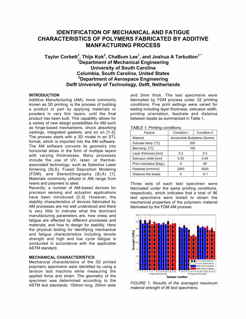
Three sets of each test specimen werefabricated under the same printing conditions,respectively, which indicates that a total of 96test specimens were tested to obtain themechanical properties of the polymeric materialfabricated by the FDM AM process.
FIGURE 1. Results of the averaged maximummaterial strength of 96 test specimens.

As a result, the test specimen fabricated under0° printing orientation and small layer thicknessshowed a high strength, 36.3 MPa. While, otherprinting conditions, feedrate and distancebetween the beads, did not have a significantinfluence on the material strength as seen inFigure 1. In the hereafter, analytical approacheswith finite element analysis will be applied foridentification of material properties [4].
FIGURE 2. In-house built flexural fatigue testmachine.
FATIGUE CHARACTERISTICSThe fatigue characteristics of the test specimensfabricated by an AM process will be identified byusing the in-house built fatigue test machine(FTM, 350mm X 350mm), which was designedin accordance with ASTM D7774-12, thestandard test method for Flexural FatigueProperties of Plastics as seen in Figure 2 [5].The in-house built FTM utilizes a scotch yokemechanism, which is a reciprocating motionmechanism to be able to convert the rotationalmotion of a motor into linear motion [6].Therefore the shape of the motion of a linearshaft connected with a DC motor is a pure sinewave over time given a constant rotationalspeed; this enables the application of time-varying cyclic loads on the test specimen. A loadcell is mounted between the end tip of the linearshaft and the test specimen. A thermopile IRsensor is placed close to the area where thecyclic load applies and used for non-contactsurface temperature measuring at the loadingzone locally because fatigue crack propagationleads to heat dissipation [7]. Also, relativehumidity and global temperature are monitoredat the same time. All the data are collected withLabView DAQ board and monitored in real time.The progressive and localized structuraldamages will be tracked by ComputedTomography (CT) scans, and then, the CTimages before and after fatigue testing will be
used to obtain quantitative estimates for theresidual internal deformations and the spatialdistribution of the deformations by usingvolumetric digital image correlation technique[8]. These results allow the identification of thefatigue and reliability characteristics of thepolymeric materials fabricated by the AMprocess under various printing conditions andallow for the comparison between well-documented theoretical models for bulkmaterials to experimental results. Furthermore, atheoretical model based on nominal strainamplitude for the fatigue life prediction of thecomplaint polymeric material will be developed.
CONCLUSIONThe methods to identify the mechanicalproperties and fatigue characteristics ofpolymeric materials fabricated by an AM processwere discussed. It was seen that the AM-basedpolymeric material properties are significantlydependent on the printing conditions, and thosefatigue characteristics are expected to bedifferent from those of bulk materials. Thefatigue model based on S/N curves, stress-straincurves and cohesive model will be developedfrom the results obtained from the mechanicaltests and CT scans. It will be used to understandthe fatigue behavior and more accuratelycharacterize the mechanical response of apolymeric material for various AM applications.
REFERENCES [1] Additive Manufacturing Market (3D printing,
laser sintering, stereolithography, fuseddeposition modeling) worth $3.5 billion by2017. MarketsandMarkets.com. Nov. 2013.
[2] Mohammad V., Hermann S., Int. J. Adv.Manuf. Technol. 2013; 67: 1721-1754.
[3] Miyakawa K., Matsuzawa R., Takahashi S.,Takamasu K. ASPE Annual Meeting 2013;56: 20-23.
[4] Yougi W., Changjie S., Xuekun S., JeffreyH., Gregory M. O., Thomas S. G., Compos.Sci. Technol. 2013; 63: 1581-1590.
[5] ASTM D7774-12, Standard Test Method forFlexural Fatigue Properties of Plastics,ASTM International, 2012.
[6] L. I. Howell. Compliant Mechanisms. JohnWiley & Sons. New York: 2001.
[7] Theddeus T. A., Omotayo A F., ISRMPolymer Science, 2013; 321489.
[8] Michael. A. S., Springer, New York: 2009.