ideacentre All-In-One 510S/520S Computer Hardware Maintenance...
75
ideacentre All-In-One 510S/520S Computer Hardware Maintenance Manual Machine Types: F0C3 [AIO 510S-23ISU / Energy Star] / F0CU [AIO 520S-23IKU / Energy Star]
Transcript of ideacentre All-In-One 510S/520S Computer Hardware Maintenance...

ideacentre All-In-One 510S/520S ComputerHardware Maintenance Manual
Machine Types: F0C3 [AIO 510S-23ISU / Energy Star] / F0CU [AIO520S-23IKU / Energy Star]


ideacentre All-In-One 510S/520S ComputerHardware Maintenance Manual
Machine Types: F0C3 [AIO 510S-23ISU / Energy Star] / F0CU [AIO520S-23IKU / Energy Star]

Second Edition (February 2017)8th
© Copyright Lenovo 2017.
LIMITED AND RESTRICTED RIGHTS NOTICE: If data or software are delivered pursuant a General ServicesAdministration “GSA” contract, use, reproduction, or disclosure is subject to restrictions set forth in Contract No.GS-35F-05925

Contents
Chapter 1. About this manual . . . . . 1Important Safety Information . . . . . . . . . 1
Chapter 2. Safety information. . . . . 3General safety . . . . . . . . . . . . . . . 3Electrical safety . . . . . . . . . . . . . . 3Safety inspection guide . . . . . . . . . . . 5Handling electrostatic discharge-sensitivedevices . . . . . . . . . . . . . . . . . 5Grounding requirements . . . . . . . . . . . 6Safety notices . . . . . . . . . . . . . . . 6
Chapter 3. General information . . . . 9Specifications . . . . . . . . . . . . . . . 9
Chapter 4. General Checkout . . . . . 11
Chapter 5. Using the Setup Utility. . . 13Starting the Lenovo BIOS Setup Utility program . 13Viewing and changing settings . . . . . . . . 13Using passwords. . . . . . . . . . . . . . 13Enabling or disabling a device . . . . . . . . 15Selecting a startup device . . . . . . . . . . 16Exiting the Lenovo BIOS Setup Utility program . . 17
Chapter 6. Symptom-to-FRU Index . . 19Hard disk drive boot error . . . . . . . . . . 19Power Supply Problems . . . . . . . . . . . 19POST error codes . . . . . . . . . . . . . 20Undetermined problems . . . . . . . . . . . 20
Chapter 7. Locating connectors,controls and components . . . . . . 21
Chapter 8. Replacing hardware . . . . 27General information. . . . . . . . . . . . . 27Replacing the keyboard and mouse . . . . . . 28Replacing the adapter . . . . . . . . . . . . 28Removing the stand base . . . . . . . . . . 29Removing the rear cover . . . . . . . . . . . 29Removing the stand holder . . . . . . . . . . 31Replacing the solid state drive . . . . . . . . 32Removing the EMI cover . . . . . . . . . . . 34Replacing the power switch board . . . . . . . 35Replacing the Wi-Fi card. . . . . . . . . . . 36Replacing the memory module . . . . . . . . 37Replacing the system fan . . . . . . . . . . 38Replacing the heat-sink . . . . . . . . . . . 39Removing the wind shielding . . . . . . . . . 40Replacing the motherboard. . . . . . . . . . 41Replacing the speaker system . . . . . . . . 42Removing the pull down assembly . . . . . . . 43Replacing the camera . . . . . . . . . . . . 44Replacing the USB board in the pull downassembly . . . . . . . . . . . . . . . . . 46Replacing the LCD panel module . . . . . . . 48Replacing the LCD panel module-None Touch . . 53
Chapter 9. FRU lists . . . . . . . . . . 57
Chapter 10. General information . . . 69Additional Service Information . . . . . . . . 69
© Copyright Lenovo 2017 iii

iv ideacentre All-In-One 510S/520S Computer Hardware Maintenance Manual

Chapter 1. About this manual
This manual contains service and reference information for Lenovo All-In-One 510S/520S computers listedon the cover. It is intended only for trained servicers who are familiar with Lenovo computer products.
Before servicing a Lenovo product, be sure to read the Safety Information.
The description of the TV-tuner card in this manual applies only to computers with a TV-tuner card installed.It does not apply to computers without a TV-tuner card.
Important Safety InformationBe sure to read all CAUTION and DANGER sections in this manual before following any of the instructions.
Veuillez lire toutes les consignes de type DANGER et ATTENTION du présent document avant d’exécuterles instructions.
Lesen Sie unbedingt alle Hinweise vom Typ “ACHTUNG” oder “VORSICHT” in dieser Dokumentation, bevorSie irgendwelche Vorgänge durchführen
Leggere le istruzioni introdotte da ATTENZIONE e PERICOLO presenti nel manuale prima di eseguire unaqualsiasi delle istruzioni
Certifique-se de ler todas as instruções de cuidado e perigo neste manual antes de executar qualqueruma das instruções
Es importante que lea todas las declaraciones de precaución y de peligro de este manual antes de seguirlas instrucciones.
© Copyright Lenovo 2017 1

2 ideacentre All-In-One 510S/520S Computer Hardware Maintenance Manual

Chapter 2. Safety information
This chapter contains the safety information that you need to be familiar with before servicing a computer.
General safetyFollow these rules to ensure general safety:
• Keep the areas around the computer clear and clean during and after maintenance.
• When lifting any heavy object:
1. Ensure you can stand safely without slipping.
2. Distribute the weight of the object equally across both feet.
3. Lift slowly. Never move suddenly or twist when you attempt to lift.
4. Lift by standing or by pushing up with your leg muscles; this action removes the strain from themuscles in your back.Do not attempt to lift any objects that weigh more than 16 kg (35 lb) or objects that you think aretoo heavy for you.
• Do not perform any action that would create a hazard for the customer, or would make the computerunsafe.
• Before you start the computer, ensure that other service representatives and customer personnel are notin a position that would create a hazard for them.
• Place removed covers and other parts in a safe place, away from all personnel, while you are servicing thecomputer.
• Keep your tool case away from areas that people may walk through to ensure no-one trips over it.
• Do not wear loose clothing that can be trapped in the moving parts of a machine. Ensure that your sleevesare fastened or rolled up above your elbows. If your hair is long, tie or fasten it back.
• Insert the ends of your necktie or scarf inside clothing or fasten it with a non-conductive clip,approximately 8 centimeters (3 inches) from the end.
• Do not wear jewelry, chains, metal-frame eyeglasses, or metal fasteners for your clothing.Remember: Metal objects are good electrical conductors.
• Wear safety glasses when you are: hammering, drilling soldering, cutting wire, attaching springs, usingsolvents, or working in any other conditions that might be hazardous to your eyes.
• After service, reinstall all safety shields, guards, labels, and ground wires. Replace any safety devicethat is worn or defective.
• Reattach all covers correctly before returning the computer to the customer.
Electrical safety
CAUTION:Electrical current from power, telephone, and communication cables can be hazardous. To avoidpersonal injury or equipment damage, disconnect any attached power cords, telecommunicationcables, network cables, and modem cables before you open the computer covers, unless instructedotherwise in the installation and configuration procedures.
© Copyright Lenovo 2017 3

Observe the following rules when working on electrical equipment.
Important: Use only approved tools and test equipment. Some hand tools have handles covered with a softmaterial that does not insulate you when working with live electrical currents. Many customers have rubberfloor mats near their equipment that contain small conductive fibers to decrease electrostatic discharge.
• Find the room emergency power-off (EPO) switch, disconnecting switch, or electrical outlet. If an electricalaccident occurs, you can then operate the switch or unplug the power cord quickly.
• Do not work alone under hazardous conditions or near equipment that has hazardous voltages.
• Disconnect all power before:
– Performing a mechanical inspection
– Working near power supplies
– Removing or installing Field Replaceable Units (FRUs)
• Before you start to work on the computer, unplug the power cord. If you cannot unplug it, ask thecustomer to power-off the electrical outlet that supplies power to the machine and to lock the electricaloutlet in the off position.
• If you need to work on a computer that has exposed electrical circuits, observe the following precautions:
– Ensure that another person, familiar with the power-off controls, is near you.Remember: Another person must be there to switch off the power, if necessary.
– Use only one hand when working with powered-on electrical equipment; keep the other hand in yourpocket or behind your back.Remember: There must be a complete circuit to cause electrical shock. By observing the above rule,you may prevent a current from passing through your body.
– When using a tester, set the controls correctly and use the approved probe leads and accessories forthat tester.
– Stand on suitable rubber mats (obtained locally, if necessary) to insulate you from grounds such asmetal floor strips and machine frames.
Observe the special safety precautions when you work with very high voltages; these instructions are inthe safety sections of the maintenance information. Use extreme care when measuring high voltages.
• Regularly inspect and maintain your electrical hand tools to ensure they are safe to use.
• Do not use worn or broken tools and testers.
• Never assume that power has been disconnected from a circuit. First, check that it has been powered off.
• Always look carefully for possible hazards in your work area. Examples of these hazards are wet floors,non-grounded power extension cables, conditions that may cause or allow power surges, and missingsafety grounds.
• Do not touch live electrical circuits with the reflective surface of a plastic dental mirror. This surface isconductive, and touching a live circuit can cause personal injury and damage to the computer.
• Do not service the following parts with the power on when they are removed from their normal operatingpositions in a computer:
– Power supply units
– Pumps
– Blowers and fans
– Motor generators
and similar units. (This practice ensures correct grounding of the units.)
• If an electrical accident occurs:
– Use caution; do not become a victim yourself.
4 ideacentre All-In-One 510S/520S Computer Hardware Maintenance Manual

– Switch off power.
– Send another person to get medical aid.
Safety inspection guideThe intent of this inspection guide is to assist you in identifying potential hazards posed by these products.Each computer, as it was designed and built, had required safety items installed to protect users andservice personnel from injury. This guide addresses only those items. However, good judgment should beused to identify potential safety hazards due to attachment of features or options not covered by thisinspection guide.
If any hazards are present, you must determine how serious the apparent hazard could be and whether youcan continue without first resolving the problem.
Consider the following items and the safety hazards they present:
• Electrical hazards, especially primary power (primary voltage on the frame can cause serious or fatalelectrical shock).
• Explosive hazards, such as a damaged CRT face or bulging capacitor
• Mechanical hazards, such as loose or missing hardware
The guide consists of a series of steps presented as a checklist. Begin the checks with the power off, andthe power cord disconnected.
Checklist:
1. Check exterior covers for damage (loose, broken, or sharp edges).
2. Power-off the computer. Disconnect the power cord.
3. Check the power cord for:
a. A third-wire ground connector in good condition. Use a meter to measure third-wire groundcontinuity for 0.1 ohm or less between the external ground pin and frame ground.
b. The power cord should be the appropriate type as specified in the parts listings.
c. Insulation must not be frayed or worn.
4. Remove the cover.
5. Check for any obvious alterations. Use good judgment as to the safety of any alterations.
6. Check inside the unit for any obvious hazards, such as metal filings, contamination, water or otherliquids, or signs of fire or smoke damage.
7. Check for worn, frayed, or pinched cables.
8. Check that the power-supply cover fasteners (screws or rivets) have not been removed or tampered with.
Handling electrostatic discharge-sensitive devicesAny computer part containing transistors or integrated circuits (ICs) should be considered sensitive toelectrostatic discharge (ESD). ESD damage can occur when there is a difference in charge between objects.Protect against ESD damage by equalizing the charge so that the computer, the part, the work mat, and theperson handling the part are all at the same charge.
Notes:
1. Use product-specific ESD procedures when they exceed the requirements noted here.
2. Make sure that the ESD protective devices you use have been certified (ISO 9000) as fully effective.
When handling ESD-sensitive parts:
Chapter 2. Safety information 5

• Keep the parts in protective packages until they are inserted into the product.
• Avoid contact with other people while handling the part.
• Wear a grounded wrist strap against your skin to eliminate static on your body.
• Prevent the part from touching your clothing. Most clothing is insulative and retains a charge evenwhen you are wearing a wrist strap.
• Use the black side of a grounded work mat to provide a static-free work surface. The mat is especiallyuseful when handling ESD-sensitive devices.
• Select a grounding system, such as those listed below, to provide protection that meets the specificservice requirement.
Note: The use of a grounding system is desirable but not required to protect against ESD damage.
– Attach the ESD ground clip to any frame ground, ground braid, or green-wire ground.
– Use an ESD common ground or reference point when working on a double-insulated orbattery-operated system. You can use coax or connector-outside shells on these systems.
– Use the round ground-prong of the AC plug on AC-operated computers.
Grounding requirementsElectrical grounding of the computer is required for operator safety and correct system function. Propergrounding of the electrical outlet can be verified by a certified electrician.
Safety noticesThe CAUTION and DANGER safety notices in this section are provided in the language of English.
DANGER
Electrical current from power, telephone and communication cables is hazardous.
To avoid a shock hazard:
• Do not connect or disconnect any cables or perform installation, maintenance, or reconfigurationof this product during an electrical storm.
• Connect all power cords to a properly wired and grounded electrical outlet.
• Connect any equipment that will be attached to this product to a properly wired outlet.
• When possible, use one hand only to connect or disconnect signal cables.
• Never turn on any equipment when there is evidence of fire, water, or structural damage.
• Disconnect the attached power cords, telecommunications cables, network cables, and modemcables before you open the device covers, unless instructed otherwise in the installation andconfiguration procedures.
• Connect and disconnect cables as described in the following table when installing, moving, oropening covers on this product or attached devices.
6 ideacentre All-In-One 510S/520S Computer Hardware Maintenance Manual

To Connect To Disconnect
1. Turn everything OFF.
2. First, attach all cables to devices.
3. Attach signal cables to connectors.
4. Attach power cords to outlet.
5. Turn device ON.
1. Turn everything OFF.
2. First, remove power cords from outlets.
3. Remove signal cables from connectors.
4. Remove all cables from devices.
CAUTION:When replacing the lithium battery, use only Part Number 45C1566 or an equivalent type batteryrecommended by the manufacturer. If your system has a module containing a lithium battery, replaceit only with the same module type made by the same manufacturer. The battery contains lithium andcan explode if not properly used, handled, or disposed of.Do not:
• Throw into or immerse in water
• Heat to more than 100°C (212°F)
• Repair or disassemble
Dispose of the battery as required by local ordinances or regulations.
CAUTION:When laser products (such as CD-ROMs, DVD-ROM drives, fiber optic devices, or transmitters) areinstalled, note the following:
• Do not remove the covers. Removing the covers of the laser product could result in exposure tohazardous laser radiation. There are no serviceable parts inside the device.
• Use of controls or adjustments or performance of procedures other than those specified hereinmight result in hazardous radiation exposure.
DANGER
Some laser products contain an embedded Class 3A or Class 3B laser diode. Note the following:
These diodes emit radiation when open. Do not stare into the beam, do not view directly withoptical instruments, and avoid direct exposure to the beam.
Chapter 2. Safety information 7

≥18 kg (37 lbs) ≥32 kg (70.5 lbs) ≥55 kg (121.2 lbs)
CAUTION:Use safe practices when lifting.
CAUTION:The power control button on the device and the power switch on the power supply do not turn offthe electrical current supplied to the device. The device also might have more than one powercord. To remove all electrical current from the device, ensure that all power cords are disconnectedfrom the power source.
1
2
CAUTION:Do not place any object weighing more than 82 kg (180 lbs.) on top of rack-mounted devices.
8 ideacentre All-In-One 510S/520S Computer Hardware Maintenance Manual

Chapter 3. General information
This chapter provides general information that applies to all computer models covered by this manual.
SpecificationsThis section lists the physical specifications for your computer.
This section lists the physical specifications for your computer.
Type Lenovo All-In-One 510S/520S
This section lists the physical specifications.
Environment
Air temperature:
Operating: 10° to 35°C
Transit: -20° to 55°C
Humidity:
Operating: 35% to 80%
Transit: 20% to 90% (40°C)
Altitude: 86KPa to 106KPa
Electrical input:
Input voltage: 90V-264V(AC)
Input frequency: 47Hz-63Hz
© Copyright Lenovo 2017 9

10 ideacentre All-In-One 510S/520S Computer Hardware Maintenance Manual

Chapter 4. General Checkout
Attention: The drives in the computer you are servicing might have been rearranged or the drive startupsequence may have been changed. Be extremely careful during write operations such as copying, saving, orformatting. Data or programs can be overwritten if you select an incorrect drive.
General error messages appear if a problem or conflict is found by an application, the operating system, orboth. For an explanation of these messages, refer to the information supplied with that software package.
Use the following procedure to help determine the cause of the problem:
1. Power-off the computer and all external devices.
2. Check all cables and power cords.
3. Set all display controls to the middle position.
4. Power-on all external devices.
5. Power-on the computer.
• Look for displayed error codes.
• Look for readable instructions or a main menu on the display.
If you did not receive the correct response, proceed to step 6.
If you did receive the correct response, proceed to step 7.
6. If one of the following happens, follow the instruction given:
• If the computer displays a POST error, go to “POST error codes”.
• If the computer hangs and no error is displayed, continue at step 7.
7. If the test stops and you cannot continue, replace the last device tested.
© Copyright Lenovo 2017 11

12 ideacentre All-In-One 510S/520S Computer Hardware Maintenance Manual
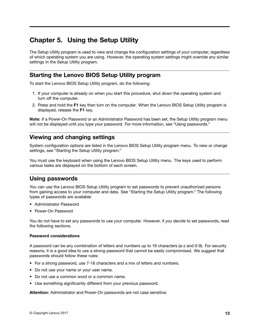
Chapter 5. Using the Setup Utility
The Setup Utility program is used to view and change the configuration settings of your computer, regardlessof which operating system you are using. However, the operating system settings might override any similarsettings in the Setup Utility program.
Starting the Lenovo BIOS Setup Utility programTo start the Lenovo BIOS Setup Utility program, do the following:
1. If your computer is already on when you start this procedure, shut down the operating system andturn off the computer.
2. Press and hold the F1 key then turn on the computer. When the Lenovo BIOS Setup Utility program isdisplayed, release the F1 key.
Note: If a Power-On Password or an Administrator Password has been set, the Setup Utility program menuwill not be displayed until you type your password. For more information, see “Using passwords.”
Viewing and changing settingsSystem configuration options are listed in the Lenovo BIOS Setup Utility program menu. To view or changesettings, see “Starting the Setup Utility program.”
You must use the keyboard when using the Lenovo BIOS Setup Utility menu. The keys used to performvarious tasks are displayed on the bottom of each screen.
Using passwordsYou can use the Lenovo BIOS Setup Utility program to set passwords to prevent unauthorized personsfrom gaining access to your computer and data. See “Starting the Setup Utility program.” The followingtypes of passwords are available:
• Administrator Password
• Power-On Password
You do not have to set any passwords to use your computer. However, if you decide to set passwords, readthe following sections.
Password considerations
A password can be any combination of letters and numbers up to 16 characters (a-z and 0-9). For securityreasons, it is a good idea to use a strong password that cannot be easily compromised. We suggest thatpasswords should follow these rules:
• For a strong password, use 7-16 characters and a mix of letters and numbers.
• Do not use your name or your user name.
• Do not use a common word or a common name.
• Use something significantly different from your previous password.
Attention: Administrator and Power-On passwords are not case sensitive.
© Copyright Lenovo 2017 13

Administrator Password
Setting an Administrator Password deters unauthorized persons from changing configuration settings. Youmight want to set an Administrator Password if you are responsible for maintaining the settings of severalcomputers.
After you set an Administrator Password, a password prompt is displayed every time you access the LenovoBIOS Setup Utility program.
If both the Administrator and Power-On Password are set, you can type either password. However, you mustuse your Administrator Password to change any configuration settings.
Setting, changing, or deleting an Administrator password
To set an Administrator Password, do the following:
Note: A password can be any combination of letters and numbers up to 16 characters (a-z and 0-9). Formore information, see “Password considerations” on page 13.
1. Start the Lenovo BIOS Setup Utility program (see “Starting the Lenovo BIOS Setup Utility program” onpage 13).
2. From the Security menu, select Set Administrator Password and press the Enter key.
3. The password dialog box will be displayed. Type the password then press the Enter key.
4. Re-type the password to confirm, then press the Enter key. If you typed the password correctly,the password will be installed.
To change an Administrator Password, do the following:
1. Start the Lenovo BIOS Setup Utility program (see “Starting the Lenovo BIOS Setup Utility program” onpage 13).
2. From the Security menu, select Set Administrator Password and press the Enter key.
3. The password dialog box will be displayed. Type the current password then press the Enter key.
4. Type the new password, then press the Enter key. Re-type the password to confirm the new password.If you typed the new password correctly, the new password will be installed. A Setup Noticed confirmingthat changes have been saved will be displayed.
To delete a previously set Administrator Password, do the following :
1. From the Security menu, select Set Administrator Password and press the Enter key.
2. The password dialog box will be displayed. Type the current password and press the Enter key.
3. To delete an Administrator Password, leave each new password line item blank, then press the Enterkey. A Setup Notice confirming that changes have been saved will be displayed.
4. Return to the Lenovo BIOS Setup Utility program menu and select the Exit option.
5. Select Save changes and Exit from the menu.
Power-On Password
When a Power-On Password is set, you cannot start the Lenovo BIOS Setup Utility program until a validpassword is typed from the keyboard.
Setting, changing, or deleting a Power-On Password
Note: A password can be any combination of letters and numbers up to 16 characters (a-z and 0-9).
14 ideacentre All-In-One 510S/520S Computer Hardware Maintenance Manual

To set a Power-On Password, do the following:
1. Start the Lenovo BIOS Setup Utility program (See ”Starting the Lenovo BIOS Setup Utility program” onpage 13.)
2. From the Security menu, select Set Power-On Password and press the Enter key.
3. The password dialog box will be displayed. Type the password, then press the Enter key.
4. Re-type the password to confirm. If you typed the password correctly, the password will be installed.
To change a Power-On Password, do the following:
1. Start the Lenovo BIOS Setup Utility program (See ”Starting the Lenovo BIOS Setup Utility program” onpage 13.)
2. From the Security menu, select Set Power-On Password and press the Enter key.
3. The password dialog box will be displayed. Type the current password then press the Enter key.
4. Type the new password, then press the Enter key. Re-type the password to confirm the new password.If you typed the new password correctly, the new password will be installed. A Setup Noticed confirmingthat changes have been saved will be displayed.
To delete a previously set Power-On Password, do the following :
1. From the Security menu, select Set Power-On Password and press the Enter key.
2. The password dialog box will be displayed. Type the current password and press the Enter key.
3. To delete the Power-On Password, leave each new password line item blank, then press Enter. A SetupNotice confirming that changes have been saved will be displayed.
4. Return to the Lenovo BIOS Setup Utility program menu and select the Exit option.
5. Select Save changes and Exit from the menu.
Enabling or disabling a deviceThe Devices options is used to enable or disable user access to the following devices:
USB Functions Select whether to enable or disable USB (Universal SerialBus) functions. If the functions are disabled, no USBdevices can be used.
SATA Mode When this feature is set to Disabled, all devicesconnected to the SATA connectors (e.g. hard disk drivesor the optical disk drive) are disabled and cannot beaccessed.
Onboard Audio Controller Select whether to enable or disable the OnboardAudio Controller. When this feature is set to Disabledall devices connected to the audio connectors (e.g.headphones or a microphone) are disabled and cannotbe used.
Onboard Ethernet Controller or LAN Boot Agent Select whether to enable or disable the Onboard EthernetController, or select whether to enable or disable loadonboard PXE (Preboot Execution Environment).
To enable or disable a device, do the following:
1. Start the Setup Utility program (see “Starting the Setup Utility program” on page 13).
2. From the Setup Utility program menu, select Devices.
3. Select an option as follows:
Select USB Setup, press the Enter key, then select USB Functions.
Chapter 5. Using the Setup Utility 15

Select ATA Device Setup, press the Enter key, then select SATA Mode.
Select Audio Setup, press the Enter key, then select Onboard Audio Controller.
Select Network Setup, press the Enter key, then select Onboard Ethernet Support or LAN BootAgent.
4. Select Disabled or Enabled and press the Enter key.
5. Return to the Lenovo BIOS Setup Utility program menu and select the Exit option.
6. Select Save changes and Exit from the menu.
Notes:
a. If you do not want to save the settings, select Discard changes and Exit from the menu.
b. Select IDE/AHCI Mode: Device driver support is required for ACHI. Depending on how the hard diskimage was installed, changing this setting may prevent the system from booting.
Selecting a startup deviceIf your computer does not boot from a device such as the CD/DVD-ROM drive disk or hard disk as expected,follow one of the procedures below.
Selecting a temporary startup device
Use this procedure to start up from any boot device.
Note: Not all CDs, DVDs or hard disk drives are bootable.
1. Turn off your computer.
2. Press and hold the F12 key then turn on the computer. When the Startup Device Menu appears,release the F12 key.
Note: If the Startup Device Menu does not display using these steps, repeatedly press and release theF12 key rather than keeping it pressed when turning on the computer.
3. Use ↑ and ↓ arrows to select the desired startup device from the Startup Device Menu and pressthe Enter key to begin.
Note: Selecting a startup device from the Startup Device Menu does not permanently change thestartup sequence.
Selecting or changing the startup device sequence
To view or permanently change the configured startup device sequence, do the following:
1. Start the Lenovo BIOS Setup Utility program (see “Starting the Lenovo BIOS Setup Utility program” onpage 13).
2. From the Lenovo BIOS Setup Utility program main menu, select the Startup option.
3. Press the Enter key, and select the devices for the Primary Boot Sequence. Read the informationdisplayed on the right side of the screen.
4. Use and ¯ arrows to select a device. Use the <+> or <-> keys to move a device up or down. Use the<×> key to exclude the device from or include the device in the boot sequence.
5. Return to the Lenovo BIOS Setup Utility program menu and select the Exit option.
6. Select Save changes and Exit from the menu.
Notes:
16 ideacentre All-In-One 510S/520S Computer Hardware Maintenance Manual

a. If you do not want to save the settings, select Discard changes and Exit from the menu.
b. If you have changed these settings and want to return to the default settings, select Load OptimalDefaults from the menu.
Exiting the Lenovo BIOS Setup Utility programAfter you finish viewing or changing settings, press the Esc key to return to the Lenovo BIOS Setup Utilityprogram main menu. You might have to press the Esc key several times. Do one of the following:
• If you want to save the new settings, select Save changes and Exit from the menu. When the Save &reset window shows, select the Yes button, and then press the Enter key to exit the Lenovo BIOSSetup Utility program.
• If you do not want to save the settings, select Discard changes and Exit from the menu. When theReset Without Saving window shows, select the Yes button, and then press the Enter key to exit theLenovo BIOS Setup Utility program.
Chapter 5. Using the Setup Utility 17

18 ideacentre All-In-One 510S/520S Computer Hardware Maintenance Manual

Chapter 6. Symptom-to-FRU Index
The Symptom-to-FRU index lists error symptoms and possible causes. The most likely cause is listed first.Always begin with Chapter 4, “General Checkout,” on page 11. This index can also be used to help youdecide which FRUs to have available when servicing a computer. If you are unable to correct the problemusing this index, go to “Undetermined problems” on page 20.
Notes:
• If you have both an error message and an incorrect audio response, diagnose the error message first.
• If you cannot run the diagnostic tests or you get a diagnostic error code when running a test but didreceive a POST error message, diagnose the POST error message first.
• If you did not receive any error message look for a description of your error symptoms in the first part ofthis index.
Hard disk drive boot errorA hard disk drive boot error can be caused by the following.
Error FRU/Action
The startup drive is not included in the boot sequenceconfiguration.
Check the configuration and ensure the startup drive isin the boot sequence.
No operating system is installed on the boot drive. Install an operating system on the boot drive.
The boot sector on the startup drive is corrupted. The drive must be formatted. Do the following:
1. Attempt to back up the data on the failing hard diskdrive.
2. Use the operating system to format the hard diskdrive.
The drive is defective. Replace the hard disk drive.
Power Supply ProblemsFollow these procedures if you suspect there is a power supply problem.
Check/Verify FRU/Action
Check that the following are properly installed:
• Power Cord
• On/Off Switch connector
• System Board Power Supply connectors
• Microprocessor connections
Reseat connectors
Check the power cord. Power Cord
Check the power-on switch. Power-on Switch
© Copyright Lenovo 2017 19

POST error codesEach time you turn the computer on, it performs a series of tests to check that the system is operatingcorrectly and that certain options are set. This series of tests is called the Power-On Self-Test, or POST.POST does the following:
• Checks some basic motherboard operations
• Checks that the memory is working correctly
• Starts video operations
• Verifies that the boot drive is working
POST Error Message Description/Action
Keyboard error Cannot initialize the keyboard. Make sure the keyboardis properly connected to the computer and that no keysare held pressed during POST. To purposely configurethe computer without a keyboard, select Keyboardlessoperation in Startup and set the option to Enabled. TheBIOS then ignores the missing keyboard during POST.
Reboot and Select proper Boot device or Insert BootMedia in selected Boot device
The BIOS was unable to find a suitable boot device. Makesure the boot drive is properly connected to the computer.Make sure you have bootable media in the boot device.
Undetermined problems1. Power-off the computer.
2. Remove or disconnect the following components (if connected or installed) one at a time.
a. External devices (modem, printer, or mouse)
b. Extended video memory
c. External Cache
d. External Cache RAM
e. Hard disk drive
f. Disk drive
3. Power-on the computer to re-test the system.
4. Repeat steps 1 through 3 until you find the failing device or component.
If all devices and components have been removed and the problem continues, replace the system board.
20 ideacentre All-In-One 510S/520S Computer Hardware Maintenance Manual

Chapter 7. Locating connectors, controls and components
This section provides illustrations to help locate the various connectors, controls and components of thecomputer.
Font view
The following illustration shows the location of controls and components on the front of the computer.
Attention: Be careful not to block any air vents on the computer. Blocked air vents can cause overheating.
1. Built-in microphones (2) 2. 2D camera
© Copyright Lenovo 2017 21

Left and right view
The following illustration shows the location of connectors, controls and components on the left and rightside of the computer.
1. USB 3.0 connectors
22 ideacentre All-In-One 510S/520S Computer Hardware Maintenance Manual

Rear view
The following illustration shows the location of connectors and components on the rear of the computer.
1. HDMI button 5. Ethernet connector
2. Power button 6. USB 3.0 connectors (2)
3. Power connector 7. Combo audio jack
4. HDMI connector
Chapter 7. Locating connectors, controls and components 23

Hardware components
The following illustration shows the components that make up your computer.
1
2
3
4
5
8
7
6
9
12
13
15
16
17
14
11
10
1. Stand holder 10. LCD panel
2. Rear cover 11. Stand base
3. Heat-sink and fan assembly 12. Pull-down assembly holder
4. Power switch board 13. USB board in pull-down assembly
5. Wind shielding 14. EMI cover
6. Motherboard 15. Pull-down assembly bracket
7. Solid state drive (SSD) 16. Camera
8. Middle frame 17. Pull-down assembly cover
9. Speaker system
24 ideacentre All-In-One 510S/520S Computer Hardware Maintenance Manual

Identifying parts on the motherboard
The motherboard (sometimes called the planar or system board) is the main circuit board in your computer.It provides basic computing functions and supports a variety of devices that are factory-installed or thatyou can install later. The following illustration shows the location of connectors and components on thefront of the motherboard.
��
����
��
�� �� �� �� �� �� �� �� �� �� �� �� ��
�� ���� ��
�� ��
�� �� �� ��
1. LVDS connector 10. Ethernet connector
2. Power switch board connector 11. USB 3.0 connector
3. Touch panel connector 12. USB 3.0 connector
4. Converter connector 13. Combo audio jack
5. Battery 14. Speaker connector
6. CPU 15. System fan connector
7. Pull-down assembly connector 16. SATA SSD connector
8. Power connector 17. Memory socket
9. HDMI connector 18. Wi-Fi card slot
Chapter 7. Locating connectors, controls and components 25

26 ideacentre All-In-One 510S/520S Computer Hardware Maintenance Manual

Chapter 8. Replacing hardware
Attention: Do not remove the computer cover or attempt any repair before reading the “Important safety information”in the Safety and Warranty Guide that was included with your computer. To obtain copies of the Safety and WarrantyGuide, go to the Support Web site at: http://consumersupport.lenovo.com.
Note: Use only parts provided by Lenovo.
General informationPre-disassembly instructions
Before starting the disassembly procedure, make sure that you do the following:
1. Turn off the power to the system and all peripherals.
2. Unplug all power and signal cables from the computer.
3. Place the system on a flat, stable surface.
© Copyright Lenovo 2017 27

Replacing the keyboard and mouseNote: Your keyboard will be connected to a USB connector at either side or at the rear of the computer.
To replace the keyboard and mouse:
Step 1. Remove any media from the drives, shut down the computer, and turn off all attached devices.
Step 2. Unplug all power cords from electrical outlets.
Step 3. Disconnect all cables attached to the computer. This includes power cords, input/output (I/O)cables, and any other cables that are connected to the computer. .
Step 4. Locate the connector for the keyboard. Refer to Locating connectors, controls and components tolocate the various connectors.
Step 5. Disconnect the defective keyboard cable from the computer and connect the new keyboard cableto the same connector.
Step 6. The mouse can be replaced using the same method.
Replacing the adapterAttention: Turn off the computer and wait 3 to 5 minutes to let it cool down before removing the cover.
Step 1. Remove any media from the drives, shut down the operating system, and turn off the computerand all attached devices.
Step 2. Disconnect the adapter from the connector on the computer, then unplug the adapter fromelectrical outlet.
28 ideacentre All-In-One 510S/520S Computer Hardware Maintenance Manual

Step 3. Connect the new adapter as shown.
Removing the stand baseAttention: Turn off the computer and wait 3 to 5 minutes to let it cool down before removing the cover.
Note: It may be helpful to place the computer face-down on a soft flat surface for this procedure. Lenovorecommends that you use a blanket, towel, or other soft cloth to protect the touch screen from scratchesor other damage.
Step 1. Remove any media from the drives, shut down the operating system, and turn off the computerand all attached devices.
Step 2. Unplug all power cords from electrical outlets.
Step 3. Disconnect all cables attached to the computer. This includes power cords, input/output (I/O)cables, and any other cables that are connected to the computer. Refer to Locating connectors,controls and components to locate the various connectors.
Step 4. Remove the rubber, and then twist the hand screw ring counter-clockwise until the stand baseis loosed. 1 2
Step 5. Remove the stand base from the stand holder and put it aside. 3
Removing the rear coverAttention: Turn off the computer and wait 3 to 5 minutes to let it cool down before removing the cover.
Chapter 8. Replacing hardware 29

Note: It may be helpful to place the computer face-down on a soft flat surface for this procedure. Lenovorecommends that you use a blanket, towel, or other soft cloth to protect the touch screen from scratchesor other damage.
Step 1. Remove any media from the drives, shut down the operating system, and turn off the computerand all attached devices.
Step 2. Unplug all power cords from electrical outlets.
Step 3. Disconnect all cables attached to the computer. This includes power cords, input/output (I/O)cables, and any other cables that are connected to the computer. Refer to Locating connectors,controls and components to locate the various connectors.
Step 4. Remove the stand base. Refer to Removing the stand base.
Step 5. Remove the two screws that secure the rear cover to the chassis.
30 ideacentre All-In-One 510S/520S Computer Hardware Maintenance Manual

Step 6. Insert a screw driver into the hole at the bottom of the device as shown, and then bend the screwdriver gently until the rear cover and the chassis are separated.
Step 7. To reattach the rear cover:
a. Align the screw holes in the rear cover with the corresponding holes in the bottom of thecomputer.
b. Press the rear cover until it snaps into position.
c. Secure the rear cover to the chassis with two screws.
Removing the stand holderAttention: Turn off the computer and wait 3 to 5 minutes to let it cool down before removing the cover.
Note: It may be helpful to place the computer face-down on a soft flat surface for this procedure. Lenovorecommends that you use a blanket, towel, or other soft cloth to protect the touch screen from scratchesor other damage.
Step 1. Remove any media from the drives, shut down the operating system, and turn off the computerand all attached devices.
Step 2. Unplug all power cords from electrical outlets.
Step 3. Disconnect all cables attached to the computer. This includes power cords, input/output (I/O)cables, and any other cables that are connected to the computer. Refer to Locating connectors,controls and components to locate the various connectors.
Step 4. Remove the stand base. Refer to Removing the stand base.
Step 5. Remove the rear cover. Refer to Removing the rear cover.
Chapter 8. Replacing hardware 31
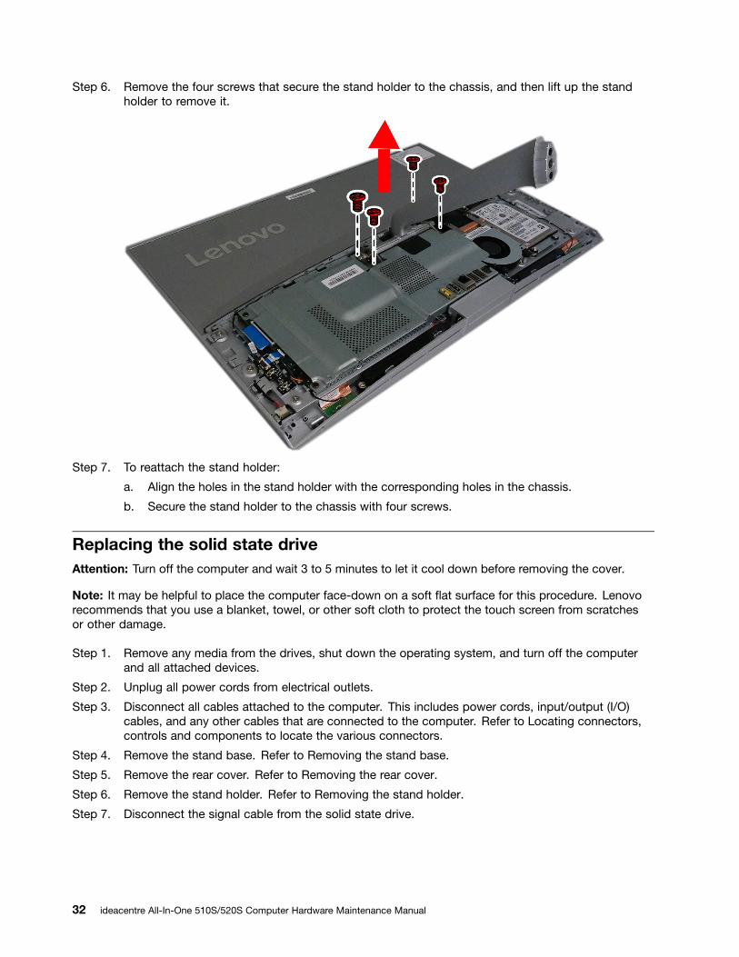
Step 6. Remove the four screws that secure the stand holder to the chassis, and then lift up the standholder to remove it.
Step 7. To reattach the stand holder:
a. Align the holes in the stand holder with the corresponding holes in the chassis.
b. Secure the stand holder to the chassis with four screws.
Replacing the solid state driveAttention: Turn off the computer and wait 3 to 5 minutes to let it cool down before removing the cover.
Note: It may be helpful to place the computer face-down on a soft flat surface for this procedure. Lenovorecommends that you use a blanket, towel, or other soft cloth to protect the touch screen from scratchesor other damage.
Step 1. Remove any media from the drives, shut down the operating system, and turn off the computerand all attached devices.
Step 2. Unplug all power cords from electrical outlets.
Step 3. Disconnect all cables attached to the computer. This includes power cords, input/output (I/O)cables, and any other cables that are connected to the computer. Refer to Locating connectors,controls and components to locate the various connectors.
Step 4. Remove the stand base. Refer to Removing the stand base.
Step 5. Remove the rear cover. Refer to Removing the rear cover.
Step 6. Remove the stand holder. Refer to Removing the stand holder.
Step 7. Disconnect the signal cable from the solid state drive.
32 ideacentre All-In-One 510S/520S Computer Hardware Maintenance Manual

Step 8. Remove the four screws that secure the storage converter to the chassis, and then remove thestorage converter.
Step 9. Remove the four screws that secure the solid state drive to the storage converter, and then removethe solid state drive from the converter.
Chapter 8. Replacing hardware 33

Step 10. To install the new solid state drive:
a. Align the holes in the new solid state drive with the corresponding holes in the storageconverter.
b. Secure the new solid state drive to the converter with four screws.
c. Reinstall the storage converter.
d. Connect the signal cable to the solid state drive.
Step 11. Reattach the stand holder, rear cover, and stand base.
Removing the EMI coverNote: Turn off the computer and wait 3 to 5 minutes to let it cool down before removing the cover.
Note: It may be helpful to place the computer face-down on a soft flat surface for this procedure. Lenovorecommends that you use a blanket, towel, or other soft cloth to protect the computer screen from scratchesor other damage.
To replace the EMI cover
Step 1. Remove any media from the drives, shut down the operating system, and turn off the computerand all attached devices.
Step 2. Unplug all power cords from electrical outlets.
Step 3. Disconnect all cables attached to the computer. This includes power cords, input/output (I/O)cables, and any other cables that are connected to the computer. Refer to Locating connectors,controls and components to locate the various connectors.
Step 4. Remove the stand base. Refer to Removing the stand base.
Step 5. Remove the rear cover. Refer to Removing the rear cover.
Step 6. Remove the stand holder. Refer to Removing the stand holder.
Step 7. Remove the five screws that secure the EMI cover to the chassis, and then lift it up.
Step 8. To install the EMI cover:
34 ideacentre All-In-One 510S/520S Computer Hardware Maintenance Manual

a. Align the holes in the EMI cover with the mounting holes in the chassis.
b. Secure the EMI cover to the chassis with five screws.
Step 9. Reattach the stand holder, rear cover, and stand base.
Replacing the power switch boardNote: Turn off the computer and wait 3 to 5 minutes to let it cool down before removing the cover.
Note: It may be helpful to place the computer face-down on a soft flat surface for this procedure. Lenovorecommends that you use a blanket, towel, or other soft cloth to protect the computer screen from scratchesor other damage.
To replace the power switch board
Step 1. Remove any media from the drives, shut down the operating system, and turn off the computerand all attached devices.
Step 2. Unplug all power cords from electrical outlets.
Step 3. Disconnect all cables attached to the computer. This includes power cords, input/output (I/O)cables, and any other cables that are connected to the computer. Refer to Locating connectors,controls and components to locate the various connectors.
Step 4. Remove the stand base. Refer to Removing the stand base.
Step 5. Remove the rear cover. Refer to Removing the rear cover.
Step 6. Remove the stand holder. Refer to Removing the stand holder.
Step 7. Remove the EMI cover. Refer to Removing the EMI cover.
Step 8. Disconnect the power switch board cable from the power switch board. 1
Step 9. Slide the power switch board out in the direction as shown. 2
Step 10. To install the power switch board:
a. Slide in the power switch board until it locks into position.
Chapter 8. Replacing hardware 35

b. Connect the cable to the new power switch board.
Step 11. Reattach the EMI cover, stand holder, rear cover, and stand base.
Replacing the Wi-Fi cardNote: Turn off the computer and wait 3 to 5 minutes to let it cool down before removing the cover.
Note: It may be helpful to place the computer face-down on a soft flat surface for this procedure. Lenovorecommends that you use a blanket, towel, or other soft cloth to protect the computer screen from scratchesor other damage.
To replace the Wi-Fi card:
Step 1. Remove any media from the drives, shut down the operating system, and turn off the computerand all attached devices.
Step 2. Unplug all power cords from electrical outlets.
Step 3. Disconnect all cables attached to the computer. This includes power cords, input/output (I/O)cables, and any other cables that are connected to the computer. Refer to Locating connectors,controls and components to locate the various connectors.
Step 4. Remove the stand base. Refer to Removing the stand base.
Step 5. Remove the rear cover. Refer to Removing the rear cover.
Step 6. Remove the stand holder. Refer to Removing the stand holder.
Step 7. Remove the EMI cover. Refer to Removing the EMI cover.
Step 8. Disconnect the antenna cables from the Wi-Fi card. 1
Step 9. Remove the screw that secures the Wi-Fi card to the motherboard. 2
Step 10. Pull the Wi-Fi card out of the slot.
Step 11. To install the new Wi-Fi card:
a. Insert the new Wi-Fi card into the Wi-Fi card slot.
36 ideacentre All-In-One 510S/520S Computer Hardware Maintenance Manual

b. Secure new the Wi-Fi card to the motherboard with the screw.
c. Connect the antenna cables to the new Wi-Fi card.
Step 12. Reattach the EMI cover, stand holder, rear cover, and stand base.
Replacing the memory moduleAttention: Turn off the computer and wait 3 to 5 minutes to let it cool down before removing the cover.
Note: It may be helpful to place the computer face-down on a soft flat surface for this procedure. Lenovorecommends that you use a blanket, towel, or other soft cloth to protect the touch screen from scratchesor other damage.
Step 1. Remove any media from the drives, shut down the operating system, and turn off the computerand all attached devices.
Step 2. Unplug all power cords from electrical outlets.
Step 3. Disconnect all cables attached to the computer. This includes power cords, input/output (I/O)cables, and any other cables that are connected to the computer. Refer to Locating connectors,controls and components to locate the various connectors.
Step 4. Remove the stand base. Refer to Removing the stand base.
Step 5. Remove the rear cover. Refer to Removing the rear cover.
Step 6. Remove the stand holder. Refer to Removing the stand holder.
Step 7. Remove the EMI cover. Refer to Removing the EMI cover.
Step 8. Open the retaining clips 1 and gently pull the memory module out of the memory socket 2 .
Step 9. To install the new memory module:
a. Position the new memory module over the memory slot. Ensure that the notch 2 on thememory module aligns correctly with the slot key 1 in the memory socket. Push the memorymodule straight down into the socket until the retaining clips close.
Chapter 8. Replacing hardware 37

Step 10. Reattach the EMI cover, stand holder, rear cover, and stand base.
Replacing the system fanNote: Turn off the computer and wait 3 to 5 minutes to let it cool down before removing the cover.
Note: It may be helpful to place the computer face-down on a soft flat surface for this procedure. Lenovorecommends that you use a blanket, towel, or other soft cloth to protect the computer screen from scratchesor other damage.
To replace the system fan
Step 1. Remove any media from the drives, shut down the operating system, and turn off the computerand all attached devices.
Step 2. Unplug all power cords from electrical outlets.
Step 3. Disconnect all cables attached to the computer. This includes power cords, input/output (I/O)cables, and any other cables that are connected to the computer. Refer to Locating connectors,controls and components to locate the various connectors.
Step 4. Remove the stand base. Refer to Removing the stand base.
Step 5. Remove the rear cover. Refer to Removing the rear cover.
Step 6. Remove the stand holder. Refer to Removing the stand holder.
Step 7. Remove the EMI cover. Refer to Removing the EMI cover.
38 ideacentre All-In-One 510S/520S Computer Hardware Maintenance Manual

Step 8. Remove the three screws that secure the system fan to the chassis.
Step 9. Disconnect the system fan power cable from the motherboard.
Step 10. Lift the system fan to remove it.
Step 11. To install the new system fan:
a. Place the new system fan into position, and then secure it to the chassis with three screws.
b. Connect the system fan power cable to the connector on the motherboard.
Step 12. Reattach the EMI cover, stand holder, rear cover, and stand base.
Replacing the heat-sinkNote: Turn off the computer and wait 3 to 5 minutes to let it cool down before removing the cover.
Note: It may be helpful to place the computer face-down on a soft flat surface for this procedure. Lenovorecommends that you use a blanket, towel, or other soft cloth to protect the computer screen from scratchesor other damage.
To replace the heat-sink:
Step 1. Remove any media from the drives, shut down the operating system, and turn off the computerand all attached devices.
Step 2. Unplug all power cords from electrical outlets.
Step 3. Disconnect all cables attached to the computer. This includes power cords, input/output (I/O)cables, and any other cables that are connected to the computer. Refer to Locating connectors,controls and components to locate the various connectors.
Step 4. Remove the stand base. Refer to Removing the stand base.
Step 5. Remove the rear cover. Refer to Removing the rear cover.
Step 6. Remove the stand holder. Refer to Removing the stand holder.
Step 7. Remove the EMI cover. Refer to Removing the EMI cover.
Chapter 8. Replacing hardware 39

Step 8. Remove the system fan. Refer to Replacing the system fan.
Step 9. Loosen the nine screws that secure the heat-sink to the motherboard and wind shielding. Then, liftthe heat-sink off the system board.
Attention: Place the heat-sink upside down on a flat surface to prevent thermal grease from contaminatingother components.
Attention: Use an alcohol pad to wipe the thermal grease off the CPU.
Step 10. To install the new heat-sink:
a. Position the new heat-sink on the motherboard so that the nine screws are aligned with theholes in the motherboard and wind shielding.
b. Tighten the screws in numeric order to secure the new heat-sink to the motherboard.
Step 11. Reattach the EMI cover, stand holder, rear cover, and stand base.
Removing the wind shieldingNote: Turn off the computer and wait 3 to 5 minutes to let it cool down before removing the cover.
Note: It may be helpful to place the computer face-down on a soft flat surface for this procedure. Lenovorecommends that you use a blanket, towel, or other soft cloth to protect the computer screen from scratchesor other damage.
To remove the wind shielding:
Step 1. Remove any media from the drives, shut down the operating system, and turn off the computerand all attached devices.
Step 2. Unplug all power cords from electrical outlets.
Step 3. Disconnect all cables attached to the computer. This includes power cords, input/output (I/O)cables, and any other cables that are connected to the computer. Refer to Locating connectors,controls and components to locate the various connectors.
40 ideacentre All-In-One 510S/520S Computer Hardware Maintenance Manual

Step 4. Remove the stand base. Refer to Removing the stand base.
Step 5. Remove the rear cover. Refer to Removing the rear cover.
Step 6. Remove the stand holder. Refer to Removing the stand holder.
Step 7. Remove the EMI cover. Refer to Removing the EMI cover.
Step 8. Remove the system fan. Refer to Replacing the system fan.
Step 9. Remove the heat sink. Refer to Replacing the heat-sink.
Step 10. Remove the two screws secure the wind shielding to the chassis.
Step 11. To install the new wind shielding:
a. Align the two holes in the new wind shielding with the mounting holes in the chassis.
b. Secure the new wind shielding to the chassis with two screws.
Step 12. Reattach the heat-sink, system fan, EMI cover, stand holder, rear cover, and stand base.
Replacing the motherboardNote: Turn off the computer and wait 3 to 5 minutes to let it cool down before removing the cover.
Note: It may be helpful to place the computer face-down on a soft flat surface for this procedure. Lenovorecommends that you use a blanket, towel, or other soft cloth to protect the computer screen from scratchesor other damage.
To replace the motherboard:
Step 1. Remove any media from the drives, shut down the operating system, and turn off the computerand all attached devices.
Step 2. Unplug all power cords from electrical outlets.
Step 3. Disconnect all cables attached to the computer. This includes power cords, input/output (I/O)cables, and any other cables that are connected to the computer. Refer to Locating connectors,controls and components to locate the various connectors.
Step 4. Remove the stand base. Refer to Removing the stand base.
Chapter 8. Replacing hardware 41

Step 5. Remove the rear cover. Refer to Removing the rear cover.
Step 6. Remove the stand holder. Refer to Removing the stand holder.
Step 7. Remove the EMI cover. Refer to Removing the EMI cover.
Step 8. Remove the memory modules. Refer to Replacing the memory module.
Step 9. Remove the system fan. Refer to Replacing the system fan.
Step 10. Remove the heat-sink. Refer to Replacing the heat-sink.
Step 11. Remove the Wi-Fi card. Refer to Replacing the Wi-Fi card.
Step 12. Remove all the cables from the motherboard.
Step 13. Remove the four screws that secure the motherboard to the chassis, and then lift the motherboardup to remove it.
Step 14. To install the new motherboard:
a. Align the four screw holes in the new motherboard with the screw holes in the chassis.
b. Secure the new motherboard to the chassis with four screws.
c. Connect all the cables to the new motherboard.
Step 15. Install the following parts to the new motherboard:
• Wi-Fi card
• Heat-sink
• System fan
• Memory module
Step 16. Reattach the EMI cover, stand holder, rear cover, and stand base.
Replacing the speaker systemNote: Turn off the computer and wait 3 to 5 minutes to let it cool down before removing the cover.
42 ideacentre All-In-One 510S/520S Computer Hardware Maintenance Manual

Note: It may be helpful to place the computer face-down on a soft flat surface for this procedure. Lenovorecommends that you use a blanket, towel, or other soft cloth to protect the computer screen from scratchesor other damage.
To replace the speaker system:
Step 1. Remove any media from the drives, shut down the operating system, and turn off the computerand all attached devices.
Step 2. Unplug all power cords from electrical outlets.
Step 3. Disconnect all cables attached to the computer. This includes power cords, input/output (I/O)cables, and any other cables that are connected to the computer. Refer to Locating connectors,controls and components to locate the various connectors.
Step 4. Remove the stand base. Refer to Removing the stand base.
Step 5. Remove the rear cover. Refer to Removing the rear cover.
Step 6. Remove the stand holder. Refer to Removing the stand holder.
Step 7. Remove the EMI cover. Refer to Removing the EMI cover.
Step 8. Remove the motherboard. Refer to Replacing the motherboard.
Step 9. Remove the four screws that secure the speaker system to the chassis. Then, lift up the speakersystem to remove it.
Step 10. To install the new speaker system:
a. Align the four screw holes in the new speaker system with the mounting holes in the chassis.
b. Secure the new speaker system to the chassis with four screws.
Step 11. Reattach the motherboard, EMI cover, stand holder, rear cover, and stand base.
Removing the pull down assemblyNote: Turn off the computer and wait 3 to 5 minutes to let it cool down before removing the cover.
Chapter 8. Replacing hardware 43

Note: It may be helpful to place the computer face-down on a soft flat surface for this procedure. Lenovorecommends that you use a blanket, towel, or other soft cloth to protect the computer screen from scratchesor other damage.
To remove the pull down assembly:
Step 1. Remove any media from the drives, shut down the operating system, and turn off the computerand all attached devices.
Step 2. Unplug all power cords from electrical outlets.
Step 3. Disconnect all cables attached to the computer. This includes power cords, input/output (I/O)cables, and any other cables that are connected to the computer. Refer to Locating connectors,controls and components to locate the various connectors.
Step 4. Remove the stand base. Refer to Removing the stand base.
Step 5. Remove the rear cover. Refer to Removing the rear cover.
Step 6. Remove the stand holder. Refer to Removing the stand holder.
Step 7. Remove the EMI cover. Refer to Removing the EMI cover.
Step 8. Remove the motherboard. Refer to Replacing the motherboard.
Step 9. Remove the two screws that secure the pull down assembly to the chassis, and then remove thepull down assembly.
Step 10. To install the pull down assembly:
a. Align the two screw holes in the new pull down assembly with the mounting holes in thechassis.
b. Secure the new pull down assembly to the chassis with two screws.
Step 11. Reattach the motherboard, EMI cover, stand holder, rear cover, and stand base.
Replacing the cameraNote: Turn off the computer and wait 3 to 5 minutes to let it cool down before removing the cover.
44 ideacentre All-In-One 510S/520S Computer Hardware Maintenance Manual

Note: It may be helpful to place the computer face-down on a soft flat surface for this procedure. Lenovorecommends that you use a blanket, towel, or other soft cloth to protect the computer screen from scratchesor other damage.
To replace the camera:
Step 1. Remove any media from the drives, shut down the operating system, and turn off the computerand all attached devices.
Step 2. Unplug all power cords from electrical outlets.
Step 3. Disconnect all cables attached to the computer. This includes power cords, input/output (I/O)cables, and any other cables that are connected to the computer. Refer to Locating connectors,controls and components to locate the various connectors.
Step 4. Remove the stand base. Refer to Removing the stand base.
Step 5. Remove the rear cover. Refer to Removing the rear cover.
Step 6. Remove the stand holder. Refer to Removing the stand holder.
Step 7. Remove the EMI cover. Refer to Removing the EMI cover.
Step 8. Remove the motherboard. Refer to Replacing the motherboard.
Step 9. Remove the pull down assembly. Refer to Removing the pull down assembly.
Step 10. Remove the two screws that secure camera and USB board to the pull down assembly cover.
Step 11. Remove the pull down assembly bracket.
Step 12. Pull the USB board and camera assembly out of the pull down assembly cover.
Chapter 8. Replacing hardware 45

Step 13. Disconnect the camera data cable from the connector in the camera.
Step 14. The camera is stick to the USB board by adhesive bandage. Separate the camera from the USBboard.
Step 15. To install the new camera:
a. Connect the data cable to the new camera.
b. Place the new camera into position, and then stick it to the USB board using adhesive bandage.
c. Secure the camera and USB board assembly to the pull down assembly cover with two screws.
d. Place the pull down assembly bracket into position.
Step 16. Reattach the pull down assembly, motherboard, EMI cover, stand holder, rear cover, and standbase.
Replacing the USB board in the pull down assemblyNote: Turn off the computer and wait 3 to 5 minutes to let it cool down before removing the cover.
Note: It may be helpful to place the computer face-down on a soft flat surface for this procedure. Lenovorecommends that you use a blanket, towel, or other soft cloth to protect the computer screen from scratchesor other damage.
To replace the USB board in the pull down assembly:
Step 1. Remove any media from the drives, shut down the operating system, and turn off the computerand all attached devices.
Step 2. Unplug all power cords from electrical outlets.
46 ideacentre All-In-One 510S/520S Computer Hardware Maintenance Manual

Step 3. Disconnect all cables attached to the computer. This includes power cords, input/output (I/O)cables, and any other cables that are connected to the computer. Refer to Locating connectors,controls and components to locate the various connectors.
Step 4. Remove the stand base. Refer to Removing the stand base.
Step 5. Remove the rear cover. Refer to Removing the rear cover.
Step 6. Remove the stand holder. Refer to Removing the stand holder.
Step 7. Remove the EMI cover. Refer to Removing the EMI cover.
Step 8. Remove the motherboard. Refer to Replacing the motherboard.
Step 9. Remove the pull down assembly. Refer to Removing the pull down assembly.
Step 10. Remove the two screws that secure camera and USB board to the pull down assembly cover.
Step 11. Remove the pull down assembly bracket.
Step 12. Pull the USB board and camera assembly out of the pull down assembly cover.
Chapter 8. Replacing hardware 47

Step 13. Disconnect the camera data cable from the connector in the USB board.
Step 14. The camera is stick to the USB board by adhesive bandage. Separate the camera from the USBboard.
Step 15. To install the new USB board:
a. Align the new USB board with the camera, and then stick it to the camera using adhesivebandage.
b. Secure the camera and USB board assembly to the pull down assembly cover with two screws.
c. Connect the camera cable to the connector in the USB board.
d. Place the pull down assembly bracket into position.
Step 16. Reattach the pull down assembly, motherboard, EMI cover, stand holder, rear cover, and standbase.
Replacing the LCD panel moduleNote: Turn off the computer and wait 3 to 5 minutes to let it cool down before removing the cover.
Note: It may be helpful to place the computer face-down on a soft flat surface for this procedure. Lenovorecommends that you use a blanket, towel, or other soft cloth to protect the computer screen from scratchesor other damage.
To replace the LCD panel module:
Step 1. Remove any media from the drives, shut down the operating system, and turn off the computerand all attached devices.
Step 2. Unplug all power cords from electrical outlets.
48 ideacentre All-In-One 510S/520S Computer Hardware Maintenance Manual

Step 3. Disconnect all cables attached to the computer. This includes power cords, input/output (I/O)cables, and any other cables that are connected to the computer. Refer to Locating connectors,controls and components to locate the various connectors.
Step 4. Remove the stand base. Refer to Removing the stand base.
Step 5. Remove the rear cover. Refer to Removing the rear cover.
Step 6. Remove the stand holder. Refer to Removing the stand holder.
Step 7. Remove the EMI cover. Refer to Removing the EMI cover.
Step 8. Remove the power switch board. Refer to Replacing the power switch board.
Step 9. Remove the system fan. Refer to Replacing the system fan.
Step 10. Remove the motherboard. Refer to Replacing the motherboard.
Step 11. Remove the wind shielding. Refer to Removing the wind shielding.
Step 12. Remove the solid state drive. Refer to Replacing the solid state drive.
Step 13. Remove the speaker system. Refer to Replacing the speaker system.
Step 14. Remove the pull down assembly. Refer to Removing the pull down assembly.
Step 15. Remove the touch cable from the connector in the LCD panel.
Chapter 8. Replacing hardware 49

Step 16. Remove the LVDS cable 1 and converter cable 2 from the connectors in the LCD panel.
Step 17. Remove the twenty one screws that secure the middle frame to the LCD panel.
50 ideacentre All-In-One 510S/520S Computer Hardware Maintenance Manual

Step 18. Pull the middle frame in the directions as shown until the panel and middle frame are separated.
Chapter 8. Replacing hardware 51

Step 19. Lift up the middle frame to remove it.
Step 20. To install the new the LCD panel module:
The new LCD panel module including: 1. LCD panel
2. Touch control board
3. Converter
a. Align the new LCD panel with the middle frame.
b. Secure the new LCD panel to the middle frame with twenty one screws.
c. Connect the LVDS, touch and converter cables to the connectors in the new LCD panel.
d. Reattach the pull down assembly to the chassis.
e. Reattach the speaker system.
f. Reattach the wind shielding.
g. Reattach the motherboard.
h. Connect the LVDS cable, touch cable, pull down assembly cable and speaker system cable tothe corresponding connectors on the motherboard.
i. Reattach the system fan.
j. Reattach the solid state drive.
k. Reattach the power switch board.
l. Connect the system fan cable, solid state drive cable and power switch board cable to thecorresponding connectors on the motherboard.
m. Reattach the EMI cover to the chassis.
n. Reattach the stand holder to the chassis.
o. Reattach the rear cover.
52 ideacentre All-In-One 510S/520S Computer Hardware Maintenance Manual

p. Reattach the stand base.
Replacing the LCD panel module-None TouchNote: Turn off the computer and wait 3 to 5 minutes to let it cool down before removing the cover.
Note: It may be helpful to place the computer face-down on a soft flat surface for this procedure. Lenovorecommends that you use a blanket, towel, or other soft cloth to protect the computer screen from scratchesor other damage.
To replace the LCD panel module:
Step 1. Remove any media from the drives, shut down the operating system, and turn off the computerand all attached devices.
Step 2. Unplug all power cords from electrical outlets.
Step 3. Disconnect all cables attached to the computer. This includes power cords, input/output (I/O)cables, and any other cables that are connected to the computer. Refer to Locating connectors,controls and components to locate the various connectors.
Step 4. Remove the stand base. Refer to Removing the stand base.
Step 5. Remove the rear cover. Refer to Removing the rear cover.
Step 6. Remove the stand holder. Refer to Removing the stand holder.
Step 7. Remove the EMI cover. Refer to Removing the EMI cover.
Step 8. Remove the power switch board. Refer to Replacing the power switch board.
Step 9. Remove the system fan. Refer to Replacing the system fan.
Step 10. Remove the motherboard. Refer to Replacing the motherboard.
Step 11. Remove the wind shielding. Refer to Removing the wind shielding.
Step 12. Remove the solid state drive. Refer to Replacing the solid state drive.
Step 13. Remove the speaker system. Refer to Replacing the speaker system.
Step 14. Remove the pull down assembly. Refer to Removing the pull down assembly.
Chapter 8. Replacing hardware 53

Step 15. Remove the LVDS cable 1 and converter cable 2 from the connectors in the LCD panel.
Step 16. Remove the twenty one screws that secure the middle frame to the LCD panel.
54 ideacentre All-In-One 510S/520S Computer Hardware Maintenance Manual

Step 17. Pull the middle frame in the directions as shown until the panel and middle frame are separated.
Chapter 8. Replacing hardware 55

Step 18. Lift up the middle frame to remove it.
Step 19. To install the new the LCD panel module:
The new LCD panel module including: 1. LCD panel
2. Converter
a. Align the new LCD panel with the middle frame.
b. Secure the new LCD panel to the middle frame with twenty one screws.
c. Connect the LVDS and converter cables to the connectors in the new LCD panel.
d. Reattach the pull down assembly the chassis.
e. Reattach the speaker system.
f. Reattach the wind shielding.
g. Reattach the motherboard.
h. Connect the LVDS cable, pull down assembly cable and speaker system cable to thecorresponding connectors on the motherboard.
i. Reattach the system fan.
j. Reattach the solid state drive.
k. Reattach the power switch board.
l. Connect the system fan cable, solid state drive cable and power switch board cable to thecorresponding connectors on the motherboard.
m. Reattach the EMI cover to the chassis.
n. Reattach the stand holder to the chassis with the four screws.
o. Reattach the rear cover.
p. Reattach the stand base.
56 ideacentre All-In-One 510S/520S Computer Hardware Maintenance Manual

Chapter 9. FRU lists
This chapter lists the information on the field replaceable units (FRUs) for ideacentre All-In-One 510S/520Sdesktop computer.
Attention: Be sure to read and understand all the safety information before replacing any FRUs.
FRU list of ideacentre AIO 510S-23ISU
FruP/N Description
AC_ADAPTER
54Y8966 AC_ADAPTER,90W,100-240V,3P
BDPLANAR
00UW319 Pentium 4405U GT930A 2G NO DPK
00UW318 Pentium 4405U GT930A 2G WIN DPK
00UW317 I3-6100U GT930A 2G NO DPK
00UW316 I3-6100U GT930A 2G WIN DPK
00UW315 I5-6200U GT930A 2G NO DPK
00UW314 I5-6200U GT930A 2G WIN DPK
00UW323 I7-6500U UMA NO DPK
00UW324 I3-6100U UMA WIN DPK
00UW325 I3-6100U UMA NO DPK
00UW322 I7-6500U UMA WIN DPK
00UW320 I7-6500U UMA WIN DPK
00UW321 I7-6500U UMA NO DPK
00UW327 Pentium 4405U UMA NO DPK
00UW326 Pentium 4405U UMA WIN DPK
00UW312 I7-6500U GT930A 2G WIN DPK
00UW313 I7-6500U GT930A 2G NO DPK
CABLE
01AG963 LGD touch LM230WF7-SSB2 Silver
00XL221 FRU,CABLE,C.A. A510S Backlight touch
00XJ068 FRU,CABLE, C.A. A510S Touch_Contro
00XJ070 FRU,CABLE, C.A. A510S LVDS_T
01AG961 LGD Touch LM230WF7-SSB3 Gold
00XL221 FRU,CABLE,C.A. A510S Backlight touch
00XJ068 FRU,CABLE, C.A. A510S Touch_Contro
00XJ070 FRU,CABLE, C.A. A510S LVDS_T
01AG964 LGD touch LM230WF7-SSB2 Silver
00XJ069 FRU,CABLE,C.A. A510S Backlight
© Copyright Lenovo 2017 57

00XJ071 FRU,CABLE,C.A. A510S LVDS_NT
01AG962 LGD Non-touch LM230WF9-SSB2 Gold
00XJ069 FRU,CABLE,C.A. A510S Backlight
00XJ071 FRU,CABLE,C.A. A510S LVDS_NT
CAMERA
01AH322 A510S 1080P 2MIC CP
CARDPOP
01AJ788 Power button Board
01AJ789 Pull down IO Board
DT_KYB
00PC217 SK-8861(CH) 2.4G KB-improved8
01AH600 2.4G SK-8861 improved8 KB HBW
00PC202 DT_KYB,DOK5321(US)W-Silk USB,US
FAN
01EF166 AVC 7012 fan for AIO510
HDD_ASM
00FC429 HDD,1TB,5400,9mm,DT2,SATA3,STD
00FC428 HDD,500G,5400,7mm,DT2,SATA3,STD
00FC432 SSHS,1TB,5400,9mm,DT2,SATA3,STD
HEATSINK
01EF164 Heatsink 15W AIO510 Intel UMA
01EF165 Heatsink 15W+12W AIO510 Intel D
KYB_MOUSE
25216265 Liteon SK-8861(IT) 2.4G KB-improved8
25209156 Sunrex EKB-10YA(SW) W-Silk USB KB-LVT8
25216251 Liteon SK-8861(US) 2.4G KB-improved8
25216271 Liteon SK-8861(US-EU) 2.4G KB-improved8
25209151 Sunrex EKB-10YA(RU) W-Silk USB KB-LVT8
25209164 Sunrex EKB-10YA(GK) W-Silk USB KB-LVT8
25209152 Sunrex EKB-10YA(UK) W-Silk USB KB-LVT8
25209165 Sunrex EKB-10YA(HG) W-Silk USB KB-LVT8
25209162 Sunrex EKB-10YA(HB) W-Silk USB KB-LVT8
25209149 Sunrex EKB-10YA(CZ-SL) W-S USB KB-LVT8
25209166 Sunrex EKB-10YA(BG) W-Silk USB KB-LVT8
25216258 Liteon SK-8861(Nordic) 2.4G KB-improved8
25209153 Sunrex EKB-10YA(Nordic) W-S USB KB-LVT8
25209161 Sunrex EKB-10YA(IT) W-Silk USB KB-LVT8
25209172 Sunrex EKB-10YA(US-EU) W-S USB KB-LVT8
25209168 Sunrex EKB-10YA(JP) W-Silk USB KB-LVT8
25216255 Liteon SK-8861(US-IN) 2.4G KB-improved8
58 ideacentre All-In-One 510S/520S Computer Hardware Maintenance Manual

25209160 Sunrex EKB-10YA(SL) W-Silk USB KB-LVT8
25216267 Liteon SK-8861(KR) 2.4G KB-improved8
25209155 Sunrex EKB-10YA(AR) W-Silk USB KB-LVT8
25209148 Sunrex EKB-10YA(TH) W-Silk USB KB-LVT8
25216254 Liteon SK-8861(CS-SK) 2.4G KB-improved8
25209146 Primax KB4721(US) W-Silk USB KB-LVT8
25216269 Liteon SK-8861(EN-FR) 2.4G KB-improved8
25209159 Sunrex EKB-10YA(SP) W-Silk USB KB-LVT8
25216259 Liteon SK-8861(LA) 2.4G KB-improved8
25209157 Sunrex EKB-10YA(GE) W-Silk USB KB-LVT8
25209147 Sunrex EKB-10YA(TW) W-Silk USB KB-LVT8
25216257 Liteon SK-8861(GB) 2.4G KB-improved8
25209145 Sunrex EKB-10YA(US) W-Silk USB KB-LVT8
25216266 Liteon SK-8861(FR) 2.4G KB-improved8
25216263 Liteon SK-8861(TR) 2.4G KB-improved8
25216270 Liteon SK-8861(BE-EN) 2.4G KB-improved8
25209169 Sunrex EKB-10YA(EN-FR) W-S USB KB-LVT8
25201322 Sunrex LXH-EMS-10ZA W-Silk Mouse
25216253 Liteon SK-8861(TH) 2.4G KB-improved8
25209158 Sunrex EKB-10YA(TR) W-Silk USB KB-LVT8
25209154 Sunrex EKB-10YA(LA) W-Silk USB KB-LVT8
25216043 Liteon ZTM600 2.4G Mouse (WW) Silver
25216264 Liteon SK-8861(ES) 2.4G KB-improved8
25209170 Sunrex EKB-10YA(PT) W-Silk USB KB-LVT8
25216252 Liteon SK-8861(TW) 2.4G KB-improved8
25209171 Sunrex EKB-10YA(BE-EN) W-S USB KB-LVT8
25209150 Sunrex EKB-10YA(IN) W-Silk USB KB-LVT8
25209163 Sunrex EKB-10YA(FR) W-Silk USB KB-LVT8
25216268 Liteon SK-8861(JP) 2.4G KB-improved8
25201068 Liteon LXH-SM-8825 W-Silk Mouse
25216261 Liteon SK-8861(SA) 2.4G KB-improved8
25216256 Liteon SK-8861(RU) 2.4G KB-improved8
25216262 Liteon SK-8861(DE) 2.4G KB-improved8
25209167 Sunrex EKB-10YA(KR) W-Silk USB KB-LVT8
LINECORD
00XL059 Fru, LINECORD,AR,1M,3P,NON-LH
00XL062 Fru, LINECORD,BR,1M,3P,NON-LH
00XL073 Fru, LINECORD,IT,1M,3P,NON-LH
00XL078 Fru, LINECORD,AU,1M,3P,NON-LH
00XL093 Fru, LINECORD,TW,1M,3P,NON-LH
Chapter 9. FRU lists 59

00XL067 Fru, LINECORD,DK,1M,3P,NON-LH
00XL068 Fru, LINECORD,DK,1M,3P,NON-LH
00XL069 Fru, LINECORD,CH,1M,3P,NON-LH
00XL089 Fru, LINECORD,CN,1M,3P,NON-LH
00XL086 Fru, LINECORD,IL,1M,3P,NON-LH
00XL092 Fru, LINECORD,TW,1M,3P,NON-LH
00XL081 Fru, LINECORD,ZA,1M,3P,NON-LH
00XL061 Fru, LINECORD,BR,1M,3P,NON-LH
00XL077 Fru, LINECORD,GB,1M,3P,NON-LH
00XL053 Fru, US/CA,1M,3P,NON-LH
00XL066 Fru, LINECORD,DK,1M,3P,NON-LH
00XL070 Fru, LINECORD,CH,1M,3P,NON-LH
00XL085 Fru, LINECORD,IL,1M,3P,NON-LH
00XL074 Fru, LINECORD,IT,1M,3P,NON-LH
00XL057 Fru, LINECORD,AR,1M,3P,NON-LH
00XL096 Fru, LINECORD,IN,1M,3P,NON-LH
00XL076 Fru, LINECORD,GB,1M,3P,NON-LH
00XL065 Fru, EU/KR,1M,3P,NON-LH
00XL082 Fru, LINECORD,ZA,1M,3P,NON-LH
00XL052 Fru, US/CA,1M,3P,NON-LH
00XL064 Fru, EU/KR,1M,3P,NON-LH
00XL080 Fru, LINECORD,AU,1M,3P,NON-LH
00XL063 Fru, EU/KR,1M,3P,NON-LH
00XL071 Fru, LINECORD,CH,1M,3P,NON-LH
00XL051 Fru,US/CA,1M,3P,NON-LH
00XL097 Fru, LINECORD,TH,1M,3P,NON-LH
00XL075 Fru, LINECORD,GB,1M,3P,NON-LH
00XL084 Fru, LINECORD,IL,1M,3P,NON-LH
00XL083 Fru, LINECORD,ZA,1M,3P,NON-LH
00XL091 Fru, LINECORD,TW,1M,3P,NON-LH
00XL058 Fru, LINECORD,AR,1M,3P,NON-LH
00XL072 Fru, LINECORD,IT,1M,3P,NON-LH
00XL003 Fru, JP,Anti-TR,1M,2P,NON-LH
00XL002 Fru, JP,Anti-TR,1M,2P,NON-LH
00XL094 Fru, LINECORD,IN,1M,3P,NON-LH
00XL090 Fru, LINECORD,CN,1M,3P,NON-LH
00XL079 Fru, LINECORD,AU,1M,3P,NON-LH
00XL060 Fru, LINECORD,BR,1M,3P,NON-LH
MECH_ASM
01EF261 ASSY_Middle_Frame
60 ideacentre All-In-One 510S/520S Computer Hardware Maintenance Manual

01EF265 ASSY_Pull-down_Holder
01EF263 ASSY_Rear_cover
01EF266 ASSY_MB_Shield
01EF267 ASSY_HDD_Cage
01EF262 ASSY_Front_Deco
01EF326 WIFI_ANTENNA_L&R_A510S
01EF264 ASSY_Pull-down_Cover
MECHANICAL
01EF269 Fin_Cover
01EF325 Pull-down_Bracket
MEMORY
03T7413 4G,SODIMM,DDR4,2133MHz
03T7415 16G,SODIMM,DDR4,2133MHz
03T7414 8G,SODIMM,DDR4,2133MHz
MOUSE
00PC593 Doking M680B W-Silk USB MC WHT
OPT_DRIVE
00XG043 EX-ODD DVD Burner DB65
SCREW
01EF324 SCREW LIST,A510S
SSD_ASM
00KT011 256G,2.5",7mm,SATA6G,SAMSG,STD
00KT046 ASM LIT V2+ 256GB
STAND
01EF260 ASSY_M_AIO510S_Base
01EF259 ASSY_M_AIO510S_UP
WIRELESS
00JT477 Wireless,CMB,LTN,NFA435
00JT507 Wireless,CMB,IN,3165 ac Ind
00JT497 Wireless,CMB,IN,3165 ac
FRU list of ideacentre AIO 520S-23IKU
FruP/N Description
54Y8966 90w Power Brick
00PC726 AC_ADAPTER,90W,100-240Vac,3P
BDPLANAR
01LM019 I5-7200U UMA WIN DPK
01LM080 I3-6006U UMA AIO520S NO DPK
01LM017 I7-7500U UMA WIN DPK
Chapter 9. FRU lists 61

01LM079 I3-6006U UMA AIO520S WIN DPK
01LM030 I3-7100U GT930A 2G NO DPK
01LM020 I5-7200U UMA NO DPK
01LM031 4415U GT930A 2G WIN DPK
01LM032 4415U GT930A 2G NO DPK
01LM022 I3-7100U UMA NO DPK
01LM018 I7-7500U UMA NO DPK
01LM021 I3-7100U UMA WIN DPK
01LM023 4415U UMA WIN DPK
01LM024 4415U UMA NO DPK
01LM028 I5-7200U GT930A 2G NO DPK
01LM025 I7-7500U GT930A 2G WIN DPK
01LM082 I3-6006U GT930A2G A520S NO DPK
01LM081 I3-6006U GT930A2G A520S WINDPK
01LM029 I3-7100U GT930A 2G WIN DPK
01LM026 I7-7500U GT930A 2G NO DPK
01LM027 I5-7200U GT930A 2G WIN DPK
CABLE
00XJ074 C.A. A510S HDD
00XJ073 C.A. A510S Function
00XJ072 C.A. A510S Webcam
00XL221 C.A. A510S Backlight touch
00XJ075 C.A. A510S Pull-down_IO
00XJ068 C.A. A510S Touch_Contro
00XJ069 C.A. A510S Backlight
00XJ070 C.A. A510S LVDS_T
00XJ071 C.A. A510S LVDS_NT
CAMERA
01AH322 A510S 1080P 2MIC CP
CARDPOP
01AJ788 Power button Board
01AJ789 Pull down IO Board
DT_KYB
00PC217 SK-8861(CH) 2.4G KB-improved8
00PC202 DT_KYB,DOK5321(US)W-Silk USB,US
01AH600 2.4G SK-8861 improved8 KB HBW
FAN
01EF166 AVC 7012 fan for AIO510
HDD_ASM
00FC428 HDD,500G,5400,7mm,DT2,SATA3,STD
62 ideacentre All-In-One 510S/520S Computer Hardware Maintenance Manual

00FC429 HDD,1TB,5400,9mm,DT2,SATA3,STD
00PC557 HDD,1TB,5400,7mm,DT2,SATA3,SMR
00FC432 SSHS,1TB,5400,9mm,DT2,SATA3,STD
HEATSINK
01EF165 Heatsink 15W+12W AIO510 Intel D
01EF164 Heatsink 15W AIO510 Intel UMA
KYB_MOUSE
25216258 Liteon SK-8861(Nordic) 2.4G KB-improved8
25209151 Sunrex EKB-10YA(RU) W-Silk USB KB-LVT8
25209162 Sunrex EKB-10YA(HB) W-Silk USB KB-LVT8
25209149 Sunrex EKB-10YA(CZ-SL) W-S USB KB-LVT8
25216257 Liteon SK-8861(GB) 2.4G KB-improved8
25209153 Sunrex EKB-10YA(Nordic) W-S USB KB-LVT8
25209161 Sunrex EKB-10YA(IT) W-Silk USB KB-LVT8
25209172 Sunrex EKB-10YA(US-EU) W-S USB KB-LVT8
25209155 Sunrex EKB-10YA(AR) W-Silk USB KB-LVT8
25209148 Sunrex EKB-10YA(TH) W-Silk USB KB-LVT8
25209159 Sunrex EKB-10YA(SP) W-Silk USB KB-LVT8
25216266 Liteon SK-8861(FR) 2.4G KB-improved8
25216265 Liteon SK-8861(IT) 2.4G KB-improved8
25216254 Liteon SK-8861(CS-SK) 2.4G KB-improved8
25209157 Sunrex EKB-10YA(GE) W-Silk USB KB-LVT8
25216252 Liteon SK-8861(TW) 2.4G KB-improved8
25216253 Liteon SK-8861(TH) 2.4G KB-improved8
25216267 Liteon SK-8861(KR) 2.4G KB-improved8
25209154 Sunrex EKB-10YA(LA) W-Silk USB KB-LVT8
25216268 Liteon SK-8861(JP) 2.4G KB-improved8
25209170 Sunrex EKB-10YA(PT) W-Silk USB KB-LVT8
25209171 Sunrex EKB-10YA(BE-EN) W-S USB KB-LVT8
25216259 Liteon SK-8861(LA) 2.4G KB-improved8
25201068 Liteon LXH-SM-8825 W-Silk Mouse
25216262 Liteon SK-8861(DE) 2.4G KB-improved8
25216261 Liteon SK-8861(SA) 2.4G KB-improved8
25209167 Sunrex EKB-10YA(KR) W-Silk USB KB-LVT8
25209156 Sunrex EKB-10YA(SW) W-Silk USB KB-LVT8
25209164 Sunrex EKB-10YA(GK) W-Silk USB KB-LVT8
25209152 Sunrex EKB-10YA(UK) W-Silk USB KB-LVT8
25209165 Sunrex EKB-10YA(HG) W-Silk USB KB-LVT8
25209166 Sunrex EKB-10YA(BG) W-Silk USB KB-LVT8
25209168 Sunrex EKB-10YA(JP) W-Silk USB KB-LVT8
Chapter 9. FRU lists 63

25209160 Sunrex EKB-10YA(SL) W-Silk USB KB-LVT8
25216271 Liteon SK-8861(US-EU) 2.4G KB-improved8
25216270 Liteon SK-8861(BE-EN) 2.4G KB-improved8
25216264 Liteon SK-8861(ES) 2.4G KB-improved8
25209146 Primax KB4721(US) W-Silk USB KB-LVT8
25216269 Liteon SK-8861(EN-FR) 2.4G KB-improved8
25216044 Liteon ZTM600 2.4G Mouse (No BTY) Silver
25209147 Sunrex EKB-10YA(TW) W-Silk USB KB-LVT8
25216251 Liteon SK-8861(US) 2.4G KB-improved8
25216043 Liteon ZTM600 2.4G Mouse (WW) Silver
25209145 Sunrex EKB-10YA(US) W-Silk USB KB-LVT8
25216263 Liteon SK-8861(TR) 2.4G KB-improved8
25216255 Liteon SK-8861(US-IN) 2.4G KB-improved8
25209169 Sunrex EKB-10YA(EN-FR) W-S USB KB-LVT8
25201322 Sunrex LXH-EMS-10ZA W-Silk Mouse
25209158 Sunrex EKB-10YA(TR) W-Silk USB KB-LVT8
25216256 Liteon SK-8861(RU) 2.4G KB-improved8
25209150 Sunrex EKB-10YA(IN) W-Silk USB KB-LVT8
25209163 Sunrex EKB-10YA(FR) W-Silk USB KB-LVT8
LINECORD
00XL002 Fru, JP,Anti-TR,1M,2P,NON-LH
00XL052 Fru, US/CA,1M,3P,NON-LH
00XL086 Fru, LINECORD,IL,1M,3P,NON-LH
00XL090 Fru, LINECORD,CN,1M,3P,NON-LH
00XL092 Fru, LINECORD,TW,1M,3P,NON-LH
00XL068 Fru, LINECORD,DK,1M,3P,NON-LH
00XL074 Fru, LINECORD,IT,1M,3P,NON-LH
00XL066 Fru, LINECORD,DK,1M,3P,NON-LH
00XL071 Fru, LINECORD,CH,1M,3P,NON-LH
00XL057 Fru, LINECORD,AR,1M,3P,NON-LH
00XL003 Fru, JP,Anti-TR,1M,2P,NON-LH
00XL079 Fru, LINECORD,AU,1M,3P,NON-LH
00XL060 Fru, LINECORD,BR,1M,3P,NON-LH
00XL058 Fru, LINECORD,AR,1M,3P,NON-LH
00XL062 Fru, LINECORD,BR,1M,3P,NON-LH
00XL096 Fru, LINECORD,IN,1M,3P,NON-LH
00XL084 Fru, LINECORD,IL,1M,3P,NON-LH
00XL070 Fru, LINECORD,CH,1M,3P,NON-LH
00XL064 Fru, EU/KR,1M,3P,NON-LH
00XL097 Fru, LINECORD,TH,1M,3P,NON-LH
64 ideacentre All-In-One 510S/520S Computer Hardware Maintenance Manual

00XL065 Fru, EU/KR,1M,3P,NON-LH
00XL091 Fru, LINECORD,TW,1M,3P,NON-LH
00XL063 Fru, EU/KR,1M,3P,NON-LH
00XL059 Fru, LINECORD,AR,1M,3P,NON-LH
00XL072 Fru, LINECORD,IT,1M,3P,NON-LH
00XL061 Fru, LINECORD,BR,1M,3P,NON-LH
00XL069 Fru, LINECORD,CH,1M,3P,NON-LH
00XL093 Fru, LINECORD,TW,1M,3P,NON-LH
00XL081 Fru, LINECORD,ZA,1M,3P,NON-LH
00XL085 Fru, LINECORD,IL,1M,3P,NON-LH
00XL053 Fru, US/CA,1M,3P,NON-LH
00XL082 Fru, LINECORD,ZA,1M,3P,NON-LH
00XL051 Fru,US/CA,1M,3P,NON-LH
00XL077 Fru, LINECORD,GB,1M,3P,NON-LH
00XL073 Fru, LINECORD,IT,1M,3P,NON-LH
00XL075 Fru, LINECORD,GB,1M,3P,NON-LH
00XL067 Fru, LINECORD,DK,1M,3P,NON-LH
00XL078 Fru, LINECORD,AU,1M,3P,NON-LH
00XL083 Fru, LINECORD,ZA,1M,3P,NON-LH
00XL080 Fru, LINECORD,AU,1M,3P,NON-LH
00XL094 Fru, LINECORD,IN,1M,3P,NON-LH
00XL076 Fru, LINECORD,GB,1M,3P,NON-LH
00XL089 Fru, LINECORD,CN,1M,3P,NON-LH
MECH_ASM
01EF565 ASSY_Pull-down_Cover,Gold
01EF564 ASSY_Rear_cover,Gold
01EF265 ASSY_Pull-down_Holder
01EF266 ASSY_MB_Shield
01EF264 ASSY_Pull-down_Cover
01EF642 Gasket,Mylar,Rubber,AIO 510S,
01EF653 FIN COVER
00XJ067 WIFI_ANTENNA_L&R_A510S
01EF563 ASSY_Front_Deco,Gold
01EF562 ASSY_Middle_Frame,Gold
01EF262 ASSY_Front_Deco
01EF261 ASSY_Middle_Frame
01EF263 ASSY_Rear_cover
01EF267 ASSY_HDD_Cage
MECHANICAL
01EF656 IO USB GASKET,AIO 510S
Chapter 9. FRU lists 65

01EF655 GASKET,8X3X1.5,AIO 510S
01EF657 Gasket 10*10*10,AIO 510S
01EF654 WIFI MYLAR,AIO 510S
01EF658 Rubber,AIO 510S,
01EF325 Pull-down_Bracket
MEMORY
01AG708 4GB DDR4 2400 SoDIMM
01AG712 8GB DDR4 2400 SoDIMM
01FR300 4G DDR4 2400 SODIMM
01AG701 4GB DDR4 2400 SoDIMM
01FR302 16G DDR4 2400 SODIMM
01AG711 8GB DDR4 2400 SoDIMM
01AG715 16GB DDR4 2400 SoDIMM
01AG714 16GB DDR4 2400 SoDIMM
01FR301 8G DDR4 2400 SODIMM
01AG702 8GB DDR4 2400 SoDIMM
01AG709 4GB DDR4 2400 SoDIMM
MOUSE
00PH143 Chicony USB Fingerprint MC B_O
00PH132 USB,Calliope,Mouse,White
00PC593 Doking M680B W-Silk USB MC WHT
OPT_DRIVE
00XG043 EX-ODD DVD Burner DB65
SCREW
01EF659 SCREW LIST,A510S,Gold
01EF324 SCREW LIST,A510S
SPEAKERINT
01AH926 AIO 510S 3W Speaker
SSD_ASM
00KT011 256G,2.5",7mm,SATA6G,SAMSG,STD
00XK720 256G,2.5",7mm,SATA3,SAM,STD
00KT046 ASM LIT V2+ 256GB
00XK736 LIT CV3 256G 2.5 ASM
STAND
01EF259 ASSY_M_AIO510S_UP
01EF260 ASSY_M_AIO510S_Base
01EF561 ASSY_M_AIO510S_Base,Gold
01EF560 ASSY_M_AIO510S_UP,Gold
WIRELESS
66 ideacentre All-In-One 510S/520S Computer Hardware Maintenance Manual

00JT507 Wireless,CMB,IN,3165 ac Ind
00JT497 Wireless,CMB,IN,3165 ac
Chapter 9. FRU lists 67

68 ideacentre All-In-One 510S/520S Computer Hardware Maintenance Manual

Chapter 10. General information
This chapter provides general information that applies to all computer models covered by this manual.
Additional Service InformationThis chapter provides additional information that the service representative might find helpful.
Power management
Power management reduces the power consumption of certain components of the computer such as thesystem power supply, processor, hard disk drives, and some monitors.
Advanced configuration and power interface (ACPI) BIOS
As this computer has an ACPI BIOS system, the operating system is allowed to control the powermanagement features of the computer and the settings for Advanced Power Management (APM) BIOS modeis ignored. Not all operating systems support ACPI BIOS mode.
Automatic Power-On features
The Automatic Power-On features within the Power Management menu allow you to enable and disablefeatures that turn on the computer automatically.
• Wake Up on Alarm: You can specify a date and time at which the computer will be turned on automatically.This can be either a single event , a daily event or a weekly event.
• Wake Up on LAN: This feature allows LAN adapter card to wake the System.
© Copyright Lenovo 2017 69


![Lenovo Ideacentre 300S Hmm 20151104 ideacentre 300S Series … · 2015. 11. 4. · ideacentre 300S Series Hardware Maintenance Manual Machine Types: 90DQ [300S-11IBR/Energy Star]](https://static.fdocuments.us/doc/165x107/60cfbab2aece5111e35d5c92/lenovo-ideacentre-300s-hmm-20151104-ideacentre-300s-series-2015-11-4-ideacentre.jpg)